JP4965810B2 - Imaging apparatus and control method thereof - Google Patents
Imaging apparatus and control method thereof Download PDFInfo
- Publication number
- JP4965810B2 JP4965810B2 JP2005104360A JP2005104360A JP4965810B2 JP 4965810 B2 JP4965810 B2 JP 4965810B2 JP 2005104360 A JP2005104360 A JP 2005104360A JP 2005104360 A JP2005104360 A JP 2005104360A JP 4965810 B2 JP4965810 B2 JP 4965810B2
- Authority
- JP
- Japan
- Prior art keywords
- time
- aperture
- aperture value
- elapsed time
- elapsed
- Prior art date
- Legal status (The legal status is an assumption and is not a legal conclusion. Google has not performed a legal analysis and makes no representation as to the accuracy of the status listed.)
- Expired - Fee Related
Links
Images


Landscapes
- Studio Devices (AREA)
- Exposure Control For Cameras (AREA)
Description
本発明は、静止画及び動画の撮影が可能な撮像装置とその制御方法に関するものである。 The present invention relates to an imaging apparatus capable of capturing still images and moving images, and a control method thereof.
従来は、静止画撮影はデジタルスチルカメラで、動画撮影はビデオカメラで行うというように製品ごとに撮影するカテゴリーが分かれていた。しかし最近は、デジタルスチルカメラで動画撮影ができるものや、ビデオカメラで静止画撮影ができるものが市販されている。このような静止画撮影及び動画撮影機能を搭載し、撮像素子を一つしか持たない製品において、既に動画撮影を開始している状態で静止画を撮影しようとする場合は、一旦、動画撮影を中断して静止画を撮影した後、再び動画撮影を開始することになる。これは、高解像度が要求される静止画撮影と、解像度よりもフレームレートが要求される動画撮影では、CCDやCMOSといった撮像素子の駆動方法が全く異なるためである。従って、静止画撮影と動画撮影を同時に行うことができず、静止画撮影と動画撮影とで撮像素子を排他的に使用しなければならない。例えば、特許文献1には、動画撮影モードでの動画像撮影中に静止画撮影モードが選択された場合、静止画像撮影の間のみ静止画撮影モードに切り換えて静止画像を撮影するデジタルカメラが記載されている。
しかし同一被写体を撮影する際、動画の撮影と静止画の撮影では最適な露出条件が異なってくる。例えば動画の撮影の場合、スミア現象による画質低下を嫌って絞りを絞ったほうが良い場合であっても、静止画の撮影では絞りを絞ることによる回折や、シャッタ速度の低下による手ブレを防ぐために、絞りを開くようにしたほうが良い場合がある。このような条件で、既に動画の撮影を開始している状態から高画質な静止画を撮影しようとした場合には絞りを変更する必要があるが、所定の絞り位置まで絞りを動かすためにはある程度の時間がかかってしまい、撮影レスポンスを低下させてしまう。かといって、絞りを動かさない場合、前述したように、撮影した静止画の画質の低下を招き、更にシャッタ速度の低下により、動画の撮影の中断時間が長くなるという問題が発生する。 However, when shooting the same subject, the optimal exposure conditions differ between moving image shooting and still image shooting. For example, in the case of movie shooting, even if it is better to squeeze the aperture to avoid image degradation due to the smear phenomenon, in order to prevent diffraction due to squeezing the aperture and camera shake due to a decrease in shutter speed, even when shooting a still image In some cases, it is better to open the aperture. Under these conditions, it is necessary to change the aperture when attempting to shoot a high-quality still image from the state where movie recording has already started, but in order to move the aperture to a predetermined aperture position It takes a certain amount of time and reduces the shooting response. However, if the aperture is not moved, as described above, there is a problem that the image quality of the captured still image is deteriorated, and further, the interruption time of moving image shooting becomes longer due to the decrease of the shutter speed.
本発明の目的は、上記従来技術の欠点を解決することにある。 An object of the present invention is to solve the above-mentioned drawbacks of the prior art.
本発明の特徴は、動画撮影状態からの静止画撮影において、静止画撮影にかかる時間を短くし、動画撮影の中断時間が極力長くならないようにする。 The feature of the present invention is that, in still image shooting from a moving image shooting state, the time taken for still image shooting is shortened so that the interruption time of moving image shooting is not as long as possible.
本発明の一態様に係る撮像装置は以下のような構成を備える。即ち、
動画撮影中に静止画撮影が可能な撮像装置であって、
被写体を撮像する撮像手段と、
絞り機構を駆動させて前記撮像手段へ入射する光量を制御する絞り制御手段と、
前記撮像手段の露光時間を制御する露光時間制御手段と、
被写体の輝度情報を取得する輝度情報取得手段と、
前記輝度情報取得手段により取得された前記輝度情報に基づいて、静止画撮影時の前記絞り機構の絞り値及び静止画撮影時の前記露光時間を演算する演算手段と、
前記絞り機構を動画撮影時の絞り値から前記演算手段により演算された第(n+1)の絞り値に変更させるのに要する第(n+1)の絞り駆動時間と前記第(n+1)の絞り値に対応させて前記演算手段により演算された第(n+1)の露光時間との和である第(n+1)の経過時間と、前記絞り機構を動画撮影時の絞り値から前記第(n+1)の絞り値よりも離れた前記演算手段により演算された第(n+2)の絞り値に変更させるのに要する第(n+2)の絞り駆動時間と前記第(n+2)の絞り値に対応させて前記演算手段により演算された第(n+2)の露光時間との和である第(n+2)の経過時間と、を比較する比較手段と、
前記比較手段の比較結果に基づいて、前記第(n+1)の経過時間が前記第(n+2)の経過時間よりも短い場合、前記第(n+1)の絞り値及び前記第(n+1)の露光時間を静止画撮影時の前記絞り値及び前記露光時間として設定する設定手段と、を有し、
前記第(n+1)の経過時間が前記第(n+2)の経過時間よりも短くない場合、変数nの初期値を0として、前記第(n+1)の経過時間が前記第(n+2)の経過時間よりも短くなるまで前記変数nを+1するごとに前記第(n+1)の経過時間と前記第(n+2)の経過時間とを比較する処理を実行し、前記第(n+1)の経過時間が前記第(n+2)の経過時間よりも短くなると、前記第(n+1)の絞り値及び前記第(n+1)の露光時間を静止画撮影時の前記絞り値及び前記露光時間として設定することを特徴とする。
An imaging device according to one embodiment of the present invention includes the following configuration. That is,
An imaging device capable of taking still images during movie shooting,
Imaging means for imaging a subject;
An aperture control means for controlling the amount of light incident on the imaging means by driving an aperture mechanism;
Exposure time control means for controlling the exposure time of the imaging means;
Luminance information acquisition means for acquiring luminance information of the subject;
Based on the luminance information acquired by the luminance information acquisition means, calculating means for calculating the aperture value of the aperture mechanism during still image shooting and the exposure time during still image shooting;
The (n + 1 ) aperture driving time and the (n + 1 ) aperture required to change the aperture mechanism from the aperture value at the time of moving image shooting to the (n + 1 ) aperture value calculated by the calculation means. wherein a first (n + 1) elapsed time which is the sum of the exposure time of the calculated by the calculating means in correspondence with the value (n + 1), the diaphragm mechanism from the aperture value at the time of moving image shooting the (n + 1 ) the (n + 2 ) th aperture driving time and the (n + 2 ) th aperture value required for changing to the (n + 2 ) th aperture value calculated by the calculation means that is further away from the aperture value. comparing means for comparing, and the elapsed time of the which is the sum of the exposure time of the (n + 2) which is calculated (n + 2) by said calculating means in correspondence,
When the (n + 1 ) elapsed time is shorter than the (n + 2 ) elapsed time based on the comparison result of the comparison means, the (n + 1 ) aperture value and the (n + 1 ) th are Setting means for setting the exposure time as the aperture value and the exposure time at the time of still image shooting ,
If the elapsed time of the first (n +1) is not shorter than the elapsed time of the first (n + 2), the initial value of the variable n as 0, elapsed time elapsed the (n + 1) -th of the first (n + 2) Every time the variable n is incremented by 1 until the time becomes shorter than the time, the (n + 1) th elapsed time and the (n + 2) elapsed time are compared, and the (n + 1) th elapsed time is becomes shorter than the elapsed time of the (n + 2), and sets as the first (n + 1) the aperture value and the exposure time at the time of still image shooting aperture value and the exposure time of the first (n + 1) of .
本発明の別の一態様に係る撮像装置は以下のような構成を備える。即ち、
動画撮影中に静止画撮影が可能な撮像装置であって、
被写体を撮像する撮像手段と、
絞り機構を駆動させて前記撮像手段へ入射する光量を制御する絞り制御手段と、
前記撮像手段の露光時間を制御する露光時間制御手段と、
被写体の輝度情報を取得する輝度情報取得手段と、
前記輝度情報取得手段により取得された前記輝度情報に基づいて、静止画撮影時の前記絞り機構の絞り値及び静止画撮影時の前記露光時間を演算する演算手段と、
前記絞り機構を動画撮影時の絞り値から前記演算手段により演算された第(n+1)の絞り値に変更させるのに要する絞り駆動時間と該第(n+1)の絞り値から前記動画撮影用の絞り値へ変更させるのに要する絞り駆動時間とが加算された第(n+1)の絞り駆動時間と前記第(n+1)の絞り値に対応させて前記演算手段により演算された第(n+1)の露光時間との和である第(n+1)の経過時間と、前記絞り機構を動画撮影時の絞り値から前記第(n+1)の絞り値よりも離れた前記演算手段により演算された第(n+2)の絞り値に変更させるのに要する絞り駆動時間と該第(n+2)の絞り値から前記動画撮影用の絞り値へ変更させるのに要する絞り駆動時間とが加算された第(n+2)の絞り駆動時間と前記第(n+2)の絞り値に対応させて前記演算手段により演算された第(n+2)の露光時間との和である第(n+2)の経過時間と、を比較する比較手段と、
前記比較手段の比較結果に基づいて、前記第(n+1)の経過時間が前記第(n+2)の経過時間よりも短い場合、前記第(n+1)の絞り値及び前記第(n+1)の露光時間を静止画撮影時の前記絞り値及び前記露光時間として設定する設定手段と、を有し、
前記第(n+1)の経過時間が前記第(n+2)の経過時間よりも短くない場合、変数nの初期値を0として、前記第(n+1)の経過時間が前記第(n+2)の経過時間よりも短くなるまで前記変数nを+1するごとに前記第(n+1)の経過時間と前記第(n+2)の経過時間とを比較する処理を実行し、前記第(n+1)の経過時間が前記第(n+2)の経過時間よりも短くなると、前記第(n+1)の絞り値及び前記第(n+1)の露光時間を静止画撮影時の前記絞り値及び前記露光時間として設定することを特徴とする。
An imaging apparatus according to another aspect of the present invention has the following configuration. That is,
An imaging device capable of taking still images during movie shooting,
Imaging means for imaging a subject;
An aperture control means for controlling the amount of light incident on the imaging means by driving an aperture mechanism;
Exposure time control means for controlling the exposure time of the imaging means;
Luminance information acquisition means for acquiring luminance information of the subject;
Based on the luminance information acquired by the luminance information acquisition means, calculating means for calculating the aperture value of the aperture mechanism during still image shooting and the exposure time during still image shooting;
The aperture drive time required to change the aperture mechanism from the aperture value at the time of moving image shooting to the (n + 1 ) th aperture value calculated by the calculating means and the (n + 1 ) th aperture value for moving image shooting the (n the diaphragm driving time required to change the aperture value and is calculated by the calculating means in correspondence to the aperture value of the a diaphragm driving time of the (n + 1) obtained by adding the (n + 1) + and the (n + 1) elapsed time which is the sum of the exposure time of 1), computed by said computing means apart than the aperture value of the said diaphragm mechanism from the aperture value at the time of moving image shooting (n + 1) th The aperture drive time required to change to the (n + 2 ) th aperture value and the aperture drive time required to change from the (n + 2 ) th aperture value to the aperture value for moving image shooting are added. the (n + 2) of the diaphragm driving time and the Comparing means for (n + 2) aperture value in correspondence of the comparing, and the elapsed time of the which is the sum of the exposure time of the (n + 2) which is calculated (n + 2) by said calculating means,
When the (n + 1 ) elapsed time is shorter than the (n + 2 ) elapsed time based on the comparison result of the comparison means, the (n + 1 ) aperture value and the (n + 1 ) th are Setting means for setting the exposure time as the aperture value and the exposure time at the time of still image shooting ,
If the elapsed time of the first (n +1) is not shorter than the elapsed time of the first (n + 2), the initial value of the variable n as 0, elapsed time elapsed the (n + 1) -th of the first (n + 2) Every time the variable n is incremented by 1 until the time becomes shorter than the time, the (n + 1) th elapsed time and the (n + 2) elapsed time are compared, and the (n + 1) th elapsed time is becomes shorter than the elapsed time of the (n + 2), and sets as the first (n + 1) the aperture value and the exposure time at the time of still image shooting aperture value and the exposure time of the first (n + 1) of .
尚、この発明の概要は、本発明に必要な特徴を全て列挙しているものでなく、よって、これら特徴群のサブコンビネーションも発明になり得る。 The outline of the present invention does not enumerate all the features necessary for the present invention, and therefore a sub-combination of these feature groups can also be an invention.
本発明によれば、動画撮影状態からの静止画撮影において、静止画撮影にかかる時間を短くし、動画撮影の再開を早くすることができる。 According to the present invention, in the still image shooting from moving Well shadow state, shortening the time required for stationary Well shadow, it is possible to quickly resume the movie shooting.
以下、添付図面を参照して本発明の好適な実施の形態を詳しく説明する。尚、以下の実施の形態は特許請求の範囲に係る発明を限定するものでなく、また本実施の形態で説明されている特徴の組み合わせの全てが発明の解決手段に必須のものとは限らない。 Hereinafter, preferred embodiments of the present invention will be described in detail with reference to the accompanying drawings. The following embodiments do not limit the invention according to the claims, and all the combinations of features described in the embodiments are not necessarily essential to the solution means of the invention. .
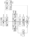
図1は、本発明の実施の形態に係る撮像装置(カメラ)の全体構成を説明するブロック図である。 FIG. 1 is a block diagram illustrating the overall configuration of an imaging apparatus (camera) according to an embodiment of the present invention.
図において、レンズ10により外光を集光する。図1では、このレンズ10は1枚として表現しているが、複数枚のレンズから構成されたレンズユニットを搭載することも可能である。また、このレンズ10を光軸に沿って前後に動かすことで焦点を調節したり、画角を調節することも可能である。このレンズ10を通過した光は絞り12により、その光量が調節される。システム制御部100は、絞り制御情報を絞り駆動回路24に伝達することで、絞り12の絞り量を制御している。システム制御部100は、CPU1001、CPU1001により実行されるプログラム(図2,図3のフローチャート)や各種データを記憶しているROM1002、CPU1001による処理時に各種データを一時的に保存するRAM1003を備えている。このシステム制御部100から絞り駆動回路24への制御情報の伝達は、シリアル通信やパルス信号などがあり、絞り駆動回路24の仕様に合わせた信号の送受信形態が採用される。絞り12は、複数枚の羽から構成された虹彩絞りや、予め板を様々な径で穴を打ち抜いた丸絞りがある。システム制御部100は、これらの絞り12と絞り駆動回路24を用い、被写体の輝度が高い場合は絞り12を絞って入射する光量を落とすように制御し、被写体の輝度が低い場合は絞り12を開放にして、入射する光量を多くするように制御する。またシステム制御部100は、シャッタ制御情報をシャッタ駆動回路25に伝達することで、シャッタ11を制御する。静止画の撮影時の露光時間は、このシャッタ11の開閉時間により決定される。この開閉時間はシステム制御部100が最適な時間を判断し、シャッタ駆動回路25に指示を出すことにより決定される。
In the figure, outside light is collected by a
レンズ10、シャッタ11、絞り12を通過した光は撮像素子14に受光される。ここでは、撮像素子14をCCD(Charge Coupled Devices)センサとしているが、CMOS(Complementary Metal Oxide Semiconductor)センサを搭載しても良い。システム制御部100は、撮像素子の制御信号をタイミング発生器(TG:Timing Generator)22に伝達することで、撮像素子14を制御している。システム制御部100からTG22への制御情報の伝達は、シリアル通信やパラレルバス通信などがあり、TG22の仕様に合わせて決定される。TG22は、システム制御部100から受信した制御情報に基づいて撮像素子14を駆動している。撮像素子14は素子への露光と、露光したデータの読み出し作業を周期的に行っており、この作業はTG22からの駆動信号を基準にして行われる。またTG22は、撮像素子14の露光時間を制御することが可能である。任意のタイミングで、素子14がチャージした電荷を解放するように、TG22から撮像素子14へ駆動信号を出力することで、これを可能としている。
The light that has passed through the
こうして撮像素子14から出力された画像信号は、CDS(Correlated Double Sampler)回路16を通過する。このCDS回路16は、相関二重サンプリング方式により画像信号に含まれるノイズ成分を除去することを主な役割とする。その後、画像信号はPGA(Programmable Gain Amplifier)回路18により、その信号レベルが増幅される。システム制御部100は、この増幅レベルをPGA回路18に伝達することで、その増幅量を制御している。システム制御部100からPGA回路18への制御情報の伝達は、シリアル通信やパラレルバス通信などがあり、PGA回路18の仕様に合わせて決定される。
The image signal output from the
通常、撮像素子14の露出を適正するには、絞り12で撮像素子14への露光量を適切に設定すると共に、TG22により撮像素子14の露光時間を適切に設定することで実現される。これと共に、PGA回路18で画像信号を増幅することにより、擬似的に画像の露出を変えることができる。例えば、被写体の輝度が極端に低い暗中の場合、絞り12を開放にして露光量が最大になるようにし、撮像素子14の露光時間を可能な限り延ばすことで、より多くの光を受光するように制御する。しかし、絞り12はある一定以上は開放できないといった機構上の制約があり、また、撮像素子14の露光時間を延ばしていくと、画像信号の更新周期が長くなるといった実用上の限界がある。この場合、画像信号の信号レベルが低くなり、露出不足として暗い画像が撮影されてしまう。この現象を改善する方法として、PGA回路18で画像信号のレベルを増幅し、画像の露出が適正になるように制御する。
Usually, the exposure of the
この後、画像信号はA/D(Analog/Digital Converter)回路20にてアナログ信号からデジタル信号へ変換される。カメラの種類に応じて、このデジタル信号のビット幅は10ビット、12ビット、14ビット等があり、後段の信号処理回路200は、複数種類のビット幅の画像データに対応可能である。
Thereafter, the image signal is converted from an analog signal to a digital signal by an A / D (Analog / Digital Converter)
尚、図1では、CDS回路14、PGA回路18、A/D回路20をそれぞれ別のブロックとして表現しているが、一つのICパッケージにこれらの機能を搭載したものを採用することも可能である。
In FIG. 1, the
こうしてデジタル化された画像データは、信号処理回路200へ入力される。信号処理回路200は、主に画質を向上させることを目的とし、様々な画像処理ブロックから構成させる。その中に画像データから輝度情報Yを抽出するY分離ブロック202がある。撮像素子14は、その素子の前面に赤(R)、緑(G)及び青(B)、或はイエロー(Y),マゼンタ(M)、シアン(C)、緑(G)の色のカラーフィルタが張られており、一画素一画素が各色でフィルタリングされる。Y分離ブロック202は、これら各画素データから色情報を排除し、輝度情報Yのみを抽出する。こうして抽出された輝度情報Yは、システム制御部100から参照することができ、撮像素子14の露出を適正にするための処理のための情報として利用される。
The digitized image data is input to the
Y分離ブロック202では、輝度情報Yを抽出する際、画像を複数のエリアに分割し、それぞれのエリアごとに輝度情報を抽出している。
In the
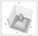
図5〜図7は、その輝度情報の抽出の概念図である。 5 to 7 are conceptual diagrams of extraction of the luminance information.
図5は、画像全体を縦横それぞれ10エリアからなる計100エリアに分割し、背後が暗く、人物が明るい被写体を撮影した画像の輝度分布を示している。図5から、背後の輝度レベルが低く、人物の輝度レベルが高い様子が分かる。 FIG. 5 shows the luminance distribution of an image obtained by dividing an entire image into 100 areas each consisting of 10 areas in the vertical and horizontal directions, and shooting a subject with a dark background and a bright person. From FIG. 5, it can be seen that the luminance level of the background is low and the luminance level of the person is high.
図6は、図5の輝度情報に対して重み付けを行った様子を示している。この図6では画像のほぼ中央部に対して最も大きな重み付けを行っている。 FIG. 6 shows a state in which the luminance information of FIG. 5 is weighted. In FIG. 6, the largest weight is applied to the substantially central portion of the image.
カメラでは撮影用途に応じて様々な測光方式を提供しており、撮影対象の画像のどの部分のどのくらいの範囲で輝度を測定するのか、モードで選択できるようになっている。このモードは、操作部34のスイッチを操作することで、ユーザが任意のモードを選択できるようになっている。
The camera provides various photometry methods depending on the shooting application, and it is possible to select in which mode the luminance is measured in which part of the image to be shot and in which mode. In this mode, the user can select an arbitrary mode by operating a switch of the
図7は、図5の輝度分布に対して図6に示す重み付けを行った後の輝度分布を示す図である。 FIG. 7 is a diagram showing the luminance distribution after the weighting shown in FIG. 6 is performed on the luminance distribution of FIG.
図5の人物の輝度分布に対し、図6のように画面中心に重みを置いた重み付けデータを掛け合わせると、人物の顔付近のエリアに、より重点を置いたものになることが分かる。この図7の重み付け後の輝度分布を画像全体で平均化し、こうして被写体輝度Yを算出する。 When the luminance distribution of the person in FIG. 5 is multiplied by weighting data in which the weight is placed at the center of the screen as shown in FIG. 6, it can be seen that more emphasis is placed on the area near the face of the person. The weighted luminance distribution in FIG. 7 is averaged over the entire image, and thus the subject luminance Y is calculated.
尚、これら図5、図6及び図7では、画像全体を10×10=100のエリアに分割した場合を示したが、分割エリアのサイズや分割数はこの限りではなく、任意に選択することが可能である。 5, 6, and 7 show the case where the entire image is divided into 10 × 10 = 100 areas. However, the size and number of division areas are not limited to this, and can be arbitrarily selected. Is possible.
こうして信号処理回路200で画像処理を行った画像データを、LCDなどの画像表示部32に出力する場合、その画像データをD/A変換器(D/A)30でアナログデータに変換する。尚、図1では、カメラ本体に搭載している画像表示部32へ表示しているが、ビデオ出力端子を搭載し、テレビなどの外部モニタとケーブル接続することで、画像をその外部モニタに表示出力することも可能である。また、この信号処理回路200で画像処理を行った画像データを、不揮発性メモリや磁気テープといった画像記憶媒体28へ記録することもできる。この画像記憶媒体28は、画像記憶媒体I/F26を介して着脱可能な形態にすることも可能である。
When the image data subjected to the image processing by the
操作部34は、電源オン/オフスイッチ、撮影開始/終了スイッチ、測光モード選択スイッチ、撮影モード選択スイッチ、再生モード選択スイッチ等を有し、ユーザがこれらスイッチを操作することで、システム制御部100に情報を伝達できる。尚、撮影開始/終了スイッチは、静止画用のスイッチと、動画用のスイッチとをそれぞれ別々に用意することができ、動画の撮影中であっても静止画の撮影を開始することができる。
The
図1に示したカメラにおいて、動画の撮影中のコンティニュアスAE(AE:AutoExposureControl)を実現するためのシステム制御部100の処理を説明する。
The processing of the
図2は、本実施の形態に係るカメラのシステム制御部100による制御処理を説明するフローチャートで、この処理を実行するプログラムはROM1002に記憶されており、CPU1001の制御の下に実行される。
FIG. 2 is a flowchart for explaining a control process by the
このフローチャートでは、プログラム線図(図4)で、実線400で示した「動画線図」上を辿ることを前提としている。このプログラム線図は、横軸をシャッタ速度Tv、縦軸を絞りAvとゲインΔGain、斜軸を露出値Evで表わしている。露出値Evと絞りAv、シャッタ速度Tv、ゲインΔGainの関係は、
Ev=Av+Tv−ΔGain ...式(1)
で表される。
In this flowchart, it is assumed that the program diagram (FIG. 4) follows the “moving diagram” indicated by the
Ev = Av + Tv-ΔGain (1)
It is represented by
各露出値Evに対して取り得る絞りAv,シャッタ速度Tv,ゲインΔGainの組み合わせを予め決めて表現したのがプログラム線図である。 The program diagram shows a predetermined combination of aperture Av, shutter speed Tv, and gain ΔGain that can be taken for each exposure value Ev.
また感度Sv、輝度Bvと露出値Evの関係は、
Sv+Bv=Ev ...式(2)
で表現される。
The relationship between sensitivity Sv, brightness Bv and exposure value Ev is
Sv + Bv = Ev Equation (2)
It is expressed by
一般的に、撮像素子(CCD)14は、様々な駆動モードを提供しており、各画素で蓄積したデータを1画素単位で出力するモードや、RGBの各同色画素同士を撮像素子14で足し合わせて出力するモードがある。このときこの画素加算の有無により、前者のモードと後者のモードではデータのレベルが異なってくるが、これを感度Svとして表現する。
In general, the image pickup device (CCD) 14 provides various drive modes. The
図4では、動画の撮影時の感度SvはSv=6、静止画撮影時の感度SvはSv=4で表している。これら感度の差により、同じ被写体輝度Bvであっても、動画撮影時と静止画撮影時とでは露出値Evが異なってくることが分かる。例えば輝度Bv=5の場合、動画の撮影時は露出値Ev=11であるが、静止画の撮影時はEv=9となる。図4で白丸401で表している露出値(斜軸方向)は、動画の撮影中の(Bv=5)+(Sv=6)での適正露出である。この時、静止画の撮影時の適正露出値は、(Bv=5)+(Sv=4)で、斜軸方向の破線402で表した線上のいずれかのポイントを使用すれば良いことになる。尚、この図4に動画線図のデータは、例えばROM1002に記憶されている。
In FIG. 4, the sensitivity Sv at the time of moving image shooting is represented by Sv = 6, and the sensitivity Sv at the time of still image shooting is represented by Sv = 4. It can be seen that due to the difference in sensitivity, the exposure value Ev differs between moving image shooting and still image shooting even with the same subject brightness Bv. For example, when the brightness Bv = 5, the exposure value Ev = 11 when shooting a moving image, but Ev = 9 when shooting a still image. The exposure value (in the direction of the oblique axis) represented by a
図2のフローチャートにおいて、まずステップS102で、露出値の初期値Evを決定し、このEvで図4のプログラム線図を引く。次にステップS104で、初期値Evとプログラム線図から、目標とする絞りAv,シャッタ速度Tv,ゲインΔGainを求める。仮に露出初期値Ev=10とすると、図4の動画線図から(Av=5,Tv=5,ΔGain=0)のポイントが導かれる。このステップS104で求めた目標値(Av=5,Tv=5,ΔGain=0)でもって、これ以降のステップで各デバイスを制御する(ステップS106,S108,S110)。 In the flowchart of FIG. 2, first, in step S102, the initial value Ev of the exposure value is determined, and the program diagram of FIG. 4 is drawn with this Ev. In step S104, the target aperture Av, shutter speed Tv, and gain ΔGain are obtained from the initial value Ev and the program diagram. If the initial exposure value Ev = 10, a point (Av = 5, Tv = 5, ΔGain = 0) is derived from the moving image diagram of FIG. Each device is controlled in the subsequent steps with the target values (Av = 5, Tv = 5, ΔGain = 0) obtained in step S104 (steps S106, S108, S110).
こうしてデバイス制御が完了して露出が確定するとステップS112に進み、被写体の輝度Yを取得する。ここでコンティニュアスAEはフィードバック制御であり、目標とする輝度YRefとの差分を「0」に近づけていく。このため、まずステップS114で、被写体輝度Yと基準(目標)とする被写体輝度YRefとの差分ΔBv0を算出する。次にステップS116で、絞りAv、シャッタ速度Tv、ゲインΔGainの分解能によっては、差分ΔBv0を「0」にするのは困難なため、差分ΔBv0が、所定の範囲内にあるかどうかを判定し、所定範囲内にあればフィードバック制御が収束したと判断する。この所定範囲は、絞りAv、シャッタ 速度Tv、ゲインΔGainの分解能を踏まえて決定するが、これを動的に決定することも可能である。 When the device control is thus completed and the exposure is confirmed, the process proceeds to step S112, and the luminance Y of the subject is acquired. Here, the continuous AE is feedback control, and the difference from the target luminance YRef is brought closer to “0”. Therefore, first, in step S114, a difference ΔBv0 between the subject brightness Y and the reference (target) subject brightness YRef is calculated. In step S116, it is difficult to set the difference ΔBv0 to “0” depending on the resolution of the aperture Av, the shutter speed Tv, and the gain ΔGain. Therefore, it is determined whether the difference ΔBv0 is within a predetermined range. If it is within the predetermined range, it is determined that the feedback control has converged. The predetermined range is determined based on the resolution of the aperture Av, the shutter speed Tv, and the gain ΔGain, but can be determined dynamically.
例えばシャッタ11は、デバイスの性格上、高速シャッタになるほど分解能が低下し、1ステップでの変化量が大きくなる。これは1ステップだけシャッタ速度Tvを変化させると、差分ΔBv0の変化量も大きくなることを意味している。よって、高速シャッタになるほど収束範囲(前述の所定範囲)を広げるなどの方法をとる。ステップS116で、差分ΔBv0が所定範囲外の場合は、まだ収束していないと判断してステップS120に進み、次のフィードバックループに進み、この差分ΔBv0に、あるフィードバックゲインをかけることで収束速度(時定数)をコントロールする。ここでは単純に、差分ΔBv0にフィードバックゲインをかけて、新たな差分ΔBv1を求める方法をとっている。しかし、これ以外にも、前回の差分ΔBv0との変化量を考慮する微分制御や、これまでの差分ΔBv0を考慮する積分制御を組み込むことも可能である。そしてステップS122で、先にステップS106,S108,S110で取得した絞りAv、シャッタ速度Tv、ゲイン値ΔGain(Av=5,Tv=5,ΔGain=0)と、ステップS120で求めた新たな差分ΔBv1とから、次の露出値Evを決定する。そして再びステップS104に進み、その露出値Evと図4のプログラム線図とから、絞りAv、シャッタ速度Tv、ゲイン値ΔGainを取得し、差分ΔBv0の収束に向けてループを形成する。
For example, as the
一方ステップS116で、差分ΔBv0が収束範囲(所定範囲)内であった場合はそこで収束完了としてステップS118に進み、一定時間周期で監視を続ける状態に入る。即ち、ステップS118で一定時間待機した後、ステップS112で、被写体輝度Yを取得し、次にステップS114で差分ΔBv0を求め、ステップS116で、差分ΔBv0が所定範囲内に入っているかどうかチェックする。この監視ループで所定範囲外と判断されると、ステップS120以降のフィードバックループに進む。 On the other hand, if the difference ΔBv0 is within the convergence range (predetermined range) in step S116, the convergence is completed and the process proceeds to step S118 to enter a state where monitoring is continued at a constant time period. That is, after waiting for a certain time in step S118, the subject luminance Y is acquired in step S112, then the difference ΔBv0 is obtained in step S114, and it is checked in step S116 whether the difference ΔBv0 is within a predetermined range. If it is determined that this monitoring loop is outside the predetermined range, the process proceeds to a feedback loop after step S120.
図3は、図2によるコンティニュアスAEを動作させて動画の撮影を行っている状態で、静止画の撮影を開始する場合の処理を説明するフローチャートで、この処理を実行するプログラムはROM1002に記憶されており、CPU1001の制御の下に実行される。
FIG. 3 is a flowchart for explaining processing when shooting a still image in a state where the continuous AE according to FIG. 2 is operated and shooting a moving image. A program for executing this processing is stored in the
まずステップS202で、現在の被写体輝度Bvを確定する。この被写体輝度Bvは、
Bv=実効絞り値Av+実効シャッタ速度Tv−実効ゲインΔGain−動画撮影中の感度SvMov(=6)+差分ΔBv0 ...式(3)
で求められる。ここで絞りAv,シャッタ速度Tv,ゲインΔGainの各実効値は、動画の撮影中に既に制御してある状態の値を使用する。ここでSvMovは、動画の撮影中の感度であり、ここでは図4において前述したようにSvMov=6とする。また差分ΔBv0は、動画の撮影中に実効Av、実効Tv、実効ΔGainで取得された適正輝度と、Y分離回路202で分離された輝度信号Yとの差分を用いる。尚、ここでカメラの仕様によっては、実効ゲインΔGainは省略しても良い。また動画の撮影時の実効シャッタ速度Tvは、静止画の撮影の場合のように、実際にシャッタ機構を動作させるのではなく、TG22によるCCD14の駆動、画像データの取り出しタイミングを変更することで実現している。
First, in step S202, the current subject brightness Bv is determined. This subject brightness Bv is
Bv = effective aperture value Av + effective shutter speed Tv−effective gain ΔGain−sensitivity SvMov (= 6) during moving image shooting + difference ΔBv0 Equation (3)
Is required. Here, as the effective values of the aperture Av, the shutter speed Tv, and the gain ΔGain, values in a state that is already controlled during moving image shooting are used. Here, SvMov is the sensitivity during shooting of a moving image, and here, SvMov = 6 as described above with reference to FIG. The difference ΔBv0 uses the difference between the appropriate luminance acquired with effective Av, effective Tv, and effective ΔGain during moving image shooting and the luminance signal Y separated by the
次にステップS204で、静止画の撮影用の露出値Evを求める。これは以下の式(4)により求められる。 In step S204, an exposure value Ev for taking a still image is obtained. This is obtained by the following equation (4).
Ev=Bv(被写体輝度)+SvCapt(静止画撮影時の感度) ...式(4)
ここでSvCaptは、静止画の撮影時の感度であり、ここでは図4で説明したようにSvCapt=Sv4とする。
Ev = Bv (subject brightness) + SvCapt (sensitivity during still image shooting) (4)
Here, SvCapt is the sensitivity at the time of shooting a still image, and here, SvCapt = Sv4 as described with reference to FIG.
更に、このステップS204では、以下のステップで使用する各パラメータ値n、実効絞り値Av0、シャッタ速度Tv0(Tv0=Ev−Av0),TimeSum0(無限大)を設定する。次にステップS206で、これら露出値Evと、実効絞り値Av0(現在の絞りAv)をnステップ動かした絞り値Av1からシャッタ速度Tv1を下式(5)により求める。 Further, in this step S204, each parameter value n, effective aperture value Av0, shutter speed Tv0 (Tv0 = Ev−Av0), and TimeSum0 (infinite) used in the following steps are set. In step S206, the shutter speed Tv1 is obtained by the following equation (5) from the exposure value Ev and the aperture value Av1 obtained by moving the effective aperture value Av0 (current aperture Av) by n steps.
Tv1=Ev−Av1 ...式(5)
次にステップS208で、実効絞り値Av(現在の絞りAv)とnステップ動かした絞り値Av1とから、静止画の撮影のために動かさなければならない絞り量を求める。更に、その絞り量と、絞り駆動速度から絞り駆動時間を算出する。そしてシャッタ速度Tv1から露光時間を算出し、静止画の撮影のための切替に要する切替時間TimeSum1を下式(6)により求める。
Tv1 = Ev−Av1 (5)
In step S208, an aperture amount that must be moved for still image shooting is obtained from the effective aperture value Av (current aperture Av) and the aperture value Av1 moved by n steps. Further, the aperture drive time is calculated from the aperture amount and the aperture drive speed. Then, the exposure time is calculated from the shutter speed Tv1, and the switching time TimeSum1 required for switching for taking a still image is obtained by the following equation (6).
TimeSum1=絞り駆動時間+露光時間 ...式(6)
次にステップS210で、ステップS208で求めたTimeSum1とTimeSum0とを比較する。ここではTimeSum0は、初期値を無限大(∞)としているため、必ずTimeSum1のほうが小さくなる。この後ステップS212に進んでループ処理に入り、絞り12を動かす(nを加算する)ことで絞り駆動時間と露光時間の和の変化を監視し、最も時間の和が小さくなるポイントを探し出す。こうしてステップS210で、実効絞り値Avをnステップ動かしたことで、TimeSum1>TimeSum0となるとステップS214に進み、TimeSum0が最も時間の和が小さいと判断する。そして、このときの絞りAv0、シャッタ速度Tv0を、静止画の撮影用の絞り値、シャッタ速度として確定する。次にステップS216で、その確定した絞りAv0に絞り12を制御し、ステップS218で、静止画を撮影する。
TimeSum1 = aperture driving time + exposure time (6)
In step S210, TimeSum1 obtained in step S208 is compared with TimeSum0. Here, since TimeSum0 has an initial value of infinity (∞), TimeSum1 is always smaller. Thereafter, the process proceeds to step S212 to enter a loop process, where the change of the sum of the aperture driving time and the exposure time is monitored by moving the aperture 12 (adding n), and the point where the sum of the times becomes the smallest is found. Thus, in step S210, the effective aperture value Av is moved by n steps, so that when TimeSum1> TimeSum0, the process proceeds to step S214, and it is determined that TimeSum0 has the smallest sum of time. Then, the aperture Av0 and shutter speed Tv0 at this time are determined as the aperture value and shutter speed for still image shooting. In step S216, the
尚、静止画の撮影が終了した後、再び動画の撮影に移行する場合においても、上記のような設定を行うことにより、動画撮影時の絞り値に変更するまでの時間が最も短くなるようにできる。このときは上記の切替時間TimeSum1に代えて下式(7)により求まるTimeSum2を用いる。 Note that even when moving to movie shooting again after the still image shooting is completed, the time required to change to the aperture value during movie shooting is minimized by performing the above settings. it can. At this time, TimeSum2 obtained by the following equation (7) is used instead of the switching time TimeSum1.
TimeSum2=絞り駆動時間+露光時間+絞り駆動時間 ...式(7)
また、静止画の撮影に切り替える直前の動画の撮影時における絞り、シャッタ速度等をシステム制御部100のメモリ(RAM1003)に記憶しておき、再び動画の撮影に移行する際に、その記憶している絞り、シャッタ速度等を読み出して絞り駆動回路24やシャッタ駆動制御に用いることにより、動画撮影時への復帰に要する時間を短縮できる。
TimeSum2 = Aperture drive time + Exposure time + Aperture drive time (7)
In addition, the aperture, shutter speed, and the like at the time of shooting a moving image immediately before switching to still image shooting are stored in the memory (RAM 1003) of the
このように本実施の形態によれば、絞り駆動時間と露光時間の和が最も小さくなる絞りAv,シャッタ速度Tvを用いて静止画を撮影することにより、撮影タイムラグの短縮化、動画の中断時間の短縮化を実現することが可能となる。これにより、静止画の撮影においてシャッタチャンスを的確に捉えることができる。なお、絞り駆動時間と露光時間の和は必ずしも最小になるよう制御されるものではない。例えば絞り駆動時間と露光時間の和が所定値以下となる絞りAv,シャッタ速度Tvのいずれかを選択する構成であってもよい。 As described above, according to the present embodiment, by taking a still image using the aperture Av and the shutter speed Tv that minimize the sum of the aperture drive time and the exposure time, the shooting time lag is shortened and the moving image is interrupted. Can be shortened. As a result, it is possible to accurately capture a photo opportunity in shooting a still image. Note that the sum of the aperture driving time and the exposure time is not necessarily controlled to be minimum. For example, it may be configured to select either the aperture Av or the shutter speed Tv at which the sum of the aperture driving time and the exposure time is a predetermined value or less.
更に、継続して動画撮影を行うというユーザの要求をバランスよく満たすことが可能となる。 Furthermore, it is possible to satisfy the user's request to continuously shoot moving images in a balanced manner.
Claims (4)
被写体を撮像する撮像手段と、
絞り機構を駆動させて前記撮像手段へ入射する光量を制御する絞り制御手段と、
前記撮像手段の露光時間を制御する露光時間制御手段と、
被写体の輝度情報を取得する輝度情報取得手段と、
前記輝度情報取得手段により取得された前記輝度情報に基づいて、静止画撮影時の前記絞り機構の絞り値及び静止画撮影時の前記露光時間を演算する演算手段と、
前記絞り機構を動画撮影時の絞り値から前記演算手段により演算された第(n+1)の絞り値に変更させるのに要する第(n+1)の絞り駆動時間と前記第(n+1)の絞り値に対応させて前記演算手段により演算された第(n+1)の露光時間との和である第(n+1)の経過時間と、前記絞り機構を動画撮影時の絞り値から前記第(n+1)の絞り値よりも離れた前記演算手段により演算された第(n+2)の絞り値に変更させるのに要する第(n+2)の絞り駆動時間と前記第(n+2)の絞り値に対応させて前記演算手段により演算された第(n+2)の露光時間との和である第(n+2)の経過時間と、を比較する比較手段と、
前記比較手段の比較結果に基づいて、前記第(n+1)の経過時間が前記第(n+2)の経過時間よりも短い場合、前記第(n+1)の絞り値及び前記第(n+1)の露光時間を静止画撮影時の前記絞り値及び前記露光時間として設定する設定手段と、を有し、
前記第(n+1)の経過時間が前記第(n+2)の経過時間よりも短くない場合、変数nの初期値を0として、前記第(n+1)の経過時間が前記第(n+2)の経過時間よりも短くなるまで前記変数nを+1するごとに前記第(n+1)の経過時間と前記第(n+2)の経過時間とを比較する処理を実行し、前記第(n+1)の経過時間が前記第(n+2)の経過時間よりも短くなると、前記第(n+1)の絞り値及び前記第(n+1)の露光時間を静止画撮影時の前記絞り値及び前記露光時間として設定することを特徴とする撮像装置。 An imaging device capable of taking still images during movie shooting,
Imaging means for imaging a subject;
An aperture control means for controlling the amount of light incident on the imaging means by driving an aperture mechanism;
Exposure time control means for controlling the exposure time of the imaging means;
Luminance information acquisition means for acquiring luminance information of the subject;
Based on the luminance information acquired by the luminance information acquisition means, calculating means for calculating the aperture value of the aperture mechanism during still image shooting and the exposure time during still image shooting;
The (n + 1 ) aperture driving time and the (n + 1 ) aperture required to change the aperture mechanism from the aperture value at the time of moving image shooting to the (n + 1 ) aperture value calculated by the calculation means. wherein a first (n + 1) elapsed time which is the sum of the exposure time of the calculated by the calculating means in correspondence with the value (n + 1), the diaphragm mechanism from the aperture value at the time of moving image shooting the (n + 1 ) the (n + 2 ) th aperture driving time and the (n + 2 ) th aperture value required for changing to the (n + 2 ) th aperture value calculated by the calculation means that is further away from the aperture value. comparing means for comparing, and the elapsed time of the which is the sum of the exposure time of the (n + 2) which is calculated (n + 2) by said calculating means in correspondence,
When the (n + 1 ) elapsed time is shorter than the (n + 2 ) elapsed time based on the comparison result of the comparison means, the (n + 1 ) aperture value and the (n + 1 ) th are Setting means for setting the exposure time as the aperture value and the exposure time at the time of still image shooting ,
If the elapsed time of the first (n +1) is not shorter than the elapsed time of the first (n + 2), the initial value of the variable n as 0, elapsed time elapsed the (n + 1) -th of the first (n + 2) Every time the variable n is incremented by 1 until the time becomes shorter than the time, the (n + 1) th elapsed time and the (n + 2) elapsed time are compared, and the (n + 1) th elapsed time is becomes shorter than the elapsed time of the (n + 2), and sets as the first (n + 1) the aperture value and the exposure time at the time of still image shooting aperture value and the exposure time of the first (n + 1) of Imaging device.
被写体を撮像する撮像手段と、
絞り機構を駆動させて前記撮像手段へ入射する光量を制御する絞り制御手段と、
前記撮像手段の露光時間を制御する露光時間制御手段と、
被写体の輝度情報を取得する輝度情報取得手段と、
前記輝度情報取得手段により取得された前記輝度情報に基づいて、静止画撮影時の前記絞り機構の絞り値及び静止画撮影時の前記露光時間を演算する演算手段と、
前記絞り機構を動画撮影時の絞り値から前記演算手段により演算された第(n+1)の絞り値に変更させるのに要する絞り駆動時間と該第(n+1)の絞り値から前記動画撮影用の絞り値へ変更させるのに要する絞り駆動時間とが加算された第(n+1)の絞り駆動時間と前記第(n+1)の絞り値に対応させて前記演算手段により演算された第(n+1)の露光時間との和である第(n+1)の経過時間と、前記絞り機構を動画撮影時の絞り値から前記第(n+1)の絞り値よりも離れた前記演算手段により演算された第(n+2)の絞り値に変更させるのに要する絞り駆動時間と該第(n+2)の絞り値から前記動画撮影用の絞り値へ変更させるのに要する絞り駆動時間とが加算された第(n+2)の絞り駆動時間と前記第(n+2)の絞り値に対応させて前記演算手段により演算された第(n+2)の露光時間との和である第(n+2)の経過時間と、を比較する比較手段と、
前記比較手段の比較結果に基づいて、前記第(n+1)の経過時間が前記第(n+2)の経過時間よりも短い場合、前記第(n+1)の絞り値及び前記第(n+1)の露光時間を静止画撮影時の前記絞り値及び前記露光時間として設定する設定手段と、を有し、
前記第(n+1)の経過時間が前記第(n+2)の経過時間よりも短くない場合、変数nの初期値を0として、前記第(n+1)の経過時間が前記第(n+2)の経過時間よりも短くなるまで前記変数nを+1するごとに前記第(n+1)の経過時間と前記第(n+2)の経過時間とを比較する処理を実行し、前記第(n+1)の経過時間が前記第(n+2)の経過時間よりも短くなると、前記第(n+1)の絞り値及び前記第(n+1)の露光時間を静止画撮影時の前記絞り値及び前記露光時間として設定することを特徴とする撮像装置。 An imaging device capable of taking still images during movie shooting,
Imaging means for imaging a subject;
An aperture control means for controlling the amount of light incident on the imaging means by driving an aperture mechanism;
Exposure time control means for controlling the exposure time of the imaging means;
Luminance information acquisition means for acquiring luminance information of the subject;
Based on the luminance information acquired by the luminance information acquisition means, calculating means for calculating the aperture value of the aperture mechanism during still image shooting and the exposure time during still image shooting;
The aperture drive time required to change the aperture mechanism from the aperture value at the time of moving image shooting to the (n + 1 ) th aperture value calculated by the calculating means and the (n + 1 ) th aperture value for moving image shooting the (n the diaphragm driving time required to change the aperture value and is calculated by the calculating means in correspondence to the aperture value of the a diaphragm driving time of the (n + 1) obtained by adding the (n + 1) + and the (n + 1) elapsed time which is the sum of the exposure time of 1), computed by said computing means apart than the aperture value of the said diaphragm mechanism from the aperture value at the time of moving image shooting (n + 1) th The aperture drive time required to change to the (n + 2 ) th aperture value and the aperture drive time required to change from the (n + 2 ) th aperture value to the aperture value for moving image shooting are added. the (n + 2) of the diaphragm driving time and the Comparing means (n + 2) aperture value in correspondence of the comparing, and the elapsed time of the which is the sum of the exposure time of the (n + 2) which is calculated (n + 2) by said calculating means,
When the (n + 1 ) elapsed time is shorter than the (n + 2 ) elapsed time based on the comparison result of the comparison means, the (n + 1 ) aperture value and the (n + 1 ) th are Setting means for setting the exposure time as the aperture value and the exposure time at the time of still image shooting ,
If the elapsed time of the first (n +1) is not shorter than the elapsed time of the first (n + 2), the initial value of the variable n as 0, elapsed time elapsed the (n + 1) -th of the first (n + 2) Every time the variable n is incremented by 1 until the time becomes shorter than the time, the (n + 1) th elapsed time and the (n + 2) elapsed time are compared, and the (n + 1) th elapsed time is becomes shorter than the elapsed time of the (n + 2), and sets as the first (n + 1) the aperture value and the exposure time at the time of still image shooting aperture value and the exposure time of the first (n + 1) of Imaging device.
被写体の輝度情報を取得する輝度情報取得ステップと、
前記輝度情報取得ステップで取得された前記輝度情報に基づいて、静止画撮影時の前記絞り機構の絞り値及び静止画撮影時の前記露光時間を演算する演算ステップと、
前記絞り機構を動画撮影時の絞り値から前記演算ステップで演算された第(n+1)の絞り値に変更させるのに要する第(n+1)の絞り駆動時間と前記第(n+1)の絞り値に対応させて前記演算ステップで演算された第(n+1)の露光時間との和である第(n+1)の経過時間と、前記絞り機構を動画撮影時の絞り値から前記第(n+1)の絞り値よりも離れた前記演算ステップで演算された第(n+2)の絞り値に変更させるのに要する第(n+2)の絞り駆動時間と前記第(n+2)の絞り値に対応させて前記演算ステップで演算された第(n+2)の露光時間との和である第(n+2)の経過時間と、を比較する比較ステップと、
前記比較ステップの比較結果に基づいて、前記第(n+1)の経過時間が前記第(n+2)の経過時間よりも短い場合、前記第(n+1)の絞り値及び前記第(n+1)の露光時間を静止画撮影時の前記絞り値及び前記露光時間として設定する設定ステップと、を有し、
前記第(n+1)の経過時間が前記第(n+2)の経過時間よりも短くない場合、変数nの初期値を0として、前記第(n+1)の経過時間が前記第(n+2)の経過時間よりも短くなるまで前記変数nを+1するごとに前記第(n+1)の経過時間と前記第(n+2)の経過時間とを比較する処理を実行し、前記第(n+1)の経過時間が前記第(n+2)の経過時間よりも短くなると、前記第(n+1)の絞り値及び前記第(n+1)の露光時間を静止画撮影時の前記絞り値及び前記露光時間として設定するステップと、
を有することを特徴とする撮像装置の制御方法。 An image capturing unit that captures an image of an object, an aperture control unit that controls an amount of light incident on the image capturing unit by driving an aperture mechanism, and an exposure time control unit that controls an exposure time of the image capturing unit. A method for controlling an image pickup apparatus capable of taking a still image,
A luminance information acquisition step for acquiring luminance information of the subject;
Based on the luminance information acquired in the luminance information acquisition step, a calculation step of calculating the aperture value of the aperture mechanism at the time of still image shooting and the exposure time at the time of still image shooting;
The (n + 1 ) aperture driving time and the (n + 1 ) aperture required to change the aperture mechanism from the aperture value at the time of moving image shooting to the (n + 1 ) aperture value calculated in the calculation step. wherein a first (n + 1) elapsed time which is the sum of the exposure time of the calculated in the calculating step to correspond to the value (n + 1), the diaphragm mechanism from the aperture value at the time of moving image shooting the (n + 1 ) the (n + 2 ) th aperture driving time and the (n + 2 ) th aperture value required to change to the (n + 2 ) th aperture value calculated in the calculation step that is further away from the aperture value. a comparison step of comparing, the elapsed time of the (n + 2) is the sum of the exposure time of the (n + 2) calculated in the calculating step to correspond,
Based on the comparison result of the comparison step, when the (n + 1 ) elapsed time is shorter than the (n + 2 ) elapsed time, the (n + 1 ) aperture value and the (n + 1 ) th time And setting the exposure time as the aperture value and the exposure time during still image shooting ,
If the elapsed time of the first (n +1) is not shorter than the elapsed time of the first (n + 2), the initial value of the variable n as 0, elapsed time elapsed the (n + 1) -th of the first (n + 2) Every time the variable n is incremented by 1 until the time becomes shorter than the time, the (n + 1) th elapsed time and the (n + 2) elapsed time are compared, and the (n + 1) th elapsed time is When the (n + 2) is shorter than the elapsed time, and setting an exposure time of the (n + 1) th aperture value and the second of (n + 1) as the aperture value and the exposure time at the time of still image shooting,
A method for controlling an imaging apparatus, comprising:
被写体の輝度情報を取得する輝度情報取得ステップと、
前記輝度情報取得ステップで取得された前記輝度情報に基づいて、静止画撮影時の前記絞り機構の絞り値及び静止画撮影時の前記露光時間を演算する演算ステップと、
前記絞り機構を動画撮影時の絞り値から前記演算ステップで演算された第(n+1)の絞り値に変更させるのに要する絞り駆動時間と該第(n+1)の絞り値から前記動画撮影用の絞り値へ変更させるのに要する絞り駆動時間とが加算された第(n+1)の絞り駆動時間と前記第(n+1)の絞り値に対応させて前記演算ステップで演算された第(n+1)の露光時間との和である第(n+1)の経過時間と、前記絞り機構を動画撮影時の絞り値から前記第(n+1)の絞り値よりも離れた前記演算ステップで演算された第(n+2)の絞り値に変更させるのに要する絞り駆動時間と該第(n+2)の絞り値から前記動画撮影用の絞り値へ変更させるのに要する絞り駆動時間とが加算された第(n+2)の絞り駆動時間と前記第(n+2)の絞り値に対応させて前記演算ステップで演算された第(n+2)の露光時間との和である第(n+2)の経過時間と、を比較する比較ステップと、
前記比較ステップの比較結果に基づいて、前記第(n+1)の経過時間が前記第(n+2)の経過時間よりも短い場合、前記第(n+1)の絞り値及び前記第(n+1)の露光時間を静止画撮影時の前記絞り値及び前記露光時間として設定する設定ステップと、を有し、
前記第(n+1)の経過時間が前記第(n+2)の経過時間よりも短くない場合、変数nの初期値を0として、前記第(n+1)の経過時間が前記第(n+2)の経過時間よりも短くなるまで前記変数nを+1するごとに前記第(n+1)の経過時間と前記第(n+2)の経過時間とを比較する処理を実行し、前記第(n+1)の経過時間が前記第(n+2)の経過時間よりも短くなると、前記第(n+1)の絞り値及び前記第(n+1)の露光時間を静止画撮影時の前記絞り値及び前記露光時間として設定するステップと、
を有することを特徴とする撮像装置の制御方法。 An image capturing unit that captures an image of an object, an aperture control unit that controls an amount of light incident on the image capturing unit by driving an aperture mechanism, and an exposure time control unit that controls an exposure time of the image capturing unit. A method for controlling an image pickup apparatus capable of taking a still image,
A luminance information acquisition step for acquiring luminance information of the subject;
Based on the luminance information acquired in the luminance information acquisition step, a calculation step of calculating the aperture value of the aperture mechanism at the time of still image shooting and the exposure time at the time of still image shooting;
For the moving image from the aperture value of the diaphragm (n + 1) th aperture driving time required for changing the aperture value and said the mechanism from aperture for movie recording is calculated by the calculation step (n + 1) the (n the diaphragm driving time required to change the aperture value and is calculated by the calculating step in correspondence to the aperture value of the a diaphragm driving time of the (n + 1) obtained by adding the (n + 1) + and the (n + 1) elapsed time which is the sum of the exposure time of 1), is calculated by the calculating step away than the aperture value of the said diaphragm mechanism from the aperture value at the time of moving image shooting (n + 1) th The aperture drive time required to change to the (n + 2 ) th aperture value and the aperture drive time required to change from the (n + 2 ) th aperture value to the aperture value for moving image shooting are added. the (n + 2) of the diaphragm driving time and the A comparing step (n + 2) aperture value in correspondence of the comparing, and the elapsed time of the (n + 2) is the sum of the exposure time of the (n + 2) calculated in the calculating step,
Based on the comparison result of the comparison step, when the (n + 1 ) elapsed time is shorter than the (n + 2 ) elapsed time, the (n + 1 ) aperture value and the (n + 1 ) th time And setting the exposure time as the aperture value and the exposure time during still image shooting ,
If the elapsed time of the first (n +1) is not shorter than the elapsed time of the first (n + 2), the initial value of the variable n as 0, elapsed time elapsed the (n + 1) -th of the first (n + 2) Every time the variable n is incremented by 1 until the time becomes shorter than the time, the (n + 1) th elapsed time and the (n + 2) elapsed time are compared, and the (n + 1) th elapsed time is When the (n + 2) is shorter than the elapsed time, and setting an exposure time of the (n + 1) th aperture value and the second of (n + 1) as the aperture value and the exposure time at the time of still image shooting,
A method for controlling an imaging apparatus, comprising:
Priority Applications (1)
| Application Number | Priority Date | Filing Date | Title |
|---|---|---|---|
| JP2005104360A JP4965810B2 (en) | 2005-03-31 | 2005-03-31 | Imaging apparatus and control method thereof |
Applications Claiming Priority (1)
| Application Number | Priority Date | Filing Date | Title |
|---|---|---|---|
| JP2005104360A JP4965810B2 (en) | 2005-03-31 | 2005-03-31 | Imaging apparatus and control method thereof |
Publications (3)
| Publication Number | Publication Date |
|---|---|
| JP2006287586A JP2006287586A (en) | 2006-10-19 |
| JP2006287586A5 JP2006287586A5 (en) | 2010-01-14 |
| JP4965810B2 true JP4965810B2 (en) | 2012-07-04 |
Family
ID=37409021
Family Applications (1)
| Application Number | Title | Priority Date | Filing Date |
|---|---|---|---|
| JP2005104360A Expired - Fee Related JP4965810B2 (en) | 2005-03-31 | 2005-03-31 | Imaging apparatus and control method thereof |
Country Status (1)
| Country | Link |
|---|---|
| JP (1) | JP4965810B2 (en) |
Families Citing this family (7)
| Publication number | Priority date | Publication date | Assignee | Title |
|---|---|---|---|---|
| US8032019B2 (en) | 2008-05-21 | 2011-10-04 | Panasonic Corporation | Camera body and imaging apparatus |
| JP5159536B2 (en) * | 2008-09-22 | 2013-03-06 | キヤノン株式会社 | Imaging apparatus, control method thereof, and program |
| JP5963102B1 (en) * | 2016-04-27 | 2016-08-03 | パナソニックIpマネジメント株式会社 | Imaging device |
| JP5995035B1 (en) * | 2016-06-17 | 2016-09-21 | パナソニックIpマネジメント株式会社 | Imaging device |
| JP6024937B2 (en) * | 2016-08-09 | 2016-11-16 | パナソニックIpマネジメント株式会社 | Imaging device |
| JP6103515B2 (en) * | 2016-12-19 | 2017-03-29 | パナソニックIpマネジメント株式会社 | Imaging device |
| JP6168249B2 (en) * | 2017-02-20 | 2017-07-26 | パナソニックIpマネジメント株式会社 | Imaging device |
Family Cites Families (6)
| Publication number | Priority date | Publication date | Assignee | Title |
|---|---|---|---|---|
| JPS5576335A (en) * | 1978-12-01 | 1980-06-09 | Fuji Photo Optical Co Ltd | Automatic exposure control unit permitting automatic fading |
| JPH0614163B2 (en) * | 1982-12-14 | 1994-02-23 | キヤノン株式会社 | Diaphragm device |
| JPH05344415A (en) * | 1992-06-09 | 1993-12-24 | Canon Inc | Automatic exposure controller for optical equipment |
| JPH0882826A (en) * | 1994-09-09 | 1996-03-26 | Canon Inc | Camera |
| JPH0993484A (en) * | 1995-09-22 | 1997-04-04 | Canon Inc | Image pickup device |
| JPH1042189A (en) * | 1996-07-24 | 1998-02-13 | Canon Inc | Electronic picture recording device |
-
2005
- 2005-03-31 JP JP2005104360A patent/JP4965810B2/en not_active Expired - Fee Related
Also Published As
| Publication number | Publication date |
|---|---|
| JP2006287586A (en) | 2006-10-19 |
Similar Documents
| Publication | Publication Date | Title |
|---|---|---|
| KR100819804B1 (en) | Photographing apparatus | |
| US7948538B2 (en) | Image capturing apparatus, image capturing method, exposure control method, and program | |
| EP2186345B1 (en) | Imaging apparatus and imaging method | |
| US8081242B2 (en) | Imaging apparatus and imaging method | |
| JP5660341B2 (en) | Imaging apparatus and imaging method | |
| JP4965810B2 (en) | Imaging apparatus and control method thereof | |
| JP4843009B2 (en) | Camera lens control method and apparatus, and camera | |
| US7884866B2 (en) | Imaging apparatus and imaging method | |
| JP2007235640A (en) | Photographing device and method | |
| US7619681B2 (en) | Image-capturing device that, when it is determined that a control value of an exposure-control exceeds a corresponding predetermined value, adjusts the control value to a value not exceeding the corresponding predetermined value, then sets the control value again based on the result of comparing luminance data obtained after an adjustment and a predetermined target luminance value, and method for controlling same | |
| JP5316923B2 (en) | Imaging apparatus and program thereof | |
| JP5310331B2 (en) | Imaging apparatus and imaging method | |
| JP2005244423A (en) | Photographing apparatus | |
| JP2010068064A (en) | Imaging device and imaging method | |
| JP5091734B2 (en) | Imaging apparatus and imaging method | |
| JP2005020341A (en) | Exposure control method and exposure controller | |
| JP2003116047A (en) | Image pickup device and photograph controlling method | |
| JP4307463B2 (en) | Imaging device | |
| JP2005117250A (en) | Imaging device | |
| JP5118003B2 (en) | Image capturing apparatus and pixel number adjusting method | |
| JP2008268361A (en) | Photographing device | |
| JP2009118158A (en) | Imaging apparatus and imaging method | |
| JP2003224858A (en) | Digital camera | |
| JP2009089358A (en) | Imaging apparatus and imaging method | |
| JP2006295722A (en) | Photographing apparatus and imaging method |
Legal Events
| Date | Code | Title | Description |
|---|---|---|---|
| A521 | Request for written amendment filed |
Free format text: JAPANESE INTERMEDIATE CODE: A523 Effective date: 20080305 |
|
| A621 | Written request for application examination |
Free format text: JAPANESE INTERMEDIATE CODE: A621 Effective date: 20080305 |
|
| A521 | Request for written amendment filed |
Free format text: JAPANESE INTERMEDIATE CODE: A523 Effective date: 20091119 |
|
| A131 | Notification of reasons for refusal |
Free format text: JAPANESE INTERMEDIATE CODE: A131 Effective date: 20100112 |
|
| A521 | Request for written amendment filed |
Free format text: JAPANESE INTERMEDIATE CODE: A523 Effective date: 20100308 |
|
| A131 | Notification of reasons for refusal |
Free format text: JAPANESE INTERMEDIATE CODE: A131 Effective date: 20100412 |
|
| A521 | Request for written amendment filed |
Free format text: JAPANESE INTERMEDIATE CODE: A523 Effective date: 20100609 |
|
| A131 | Notification of reasons for refusal |
Free format text: JAPANESE INTERMEDIATE CODE: A131 Effective date: 20100702 |
|
| A521 | Request for written amendment filed |
Free format text: JAPANESE INTERMEDIATE CODE: A523 Effective date: 20100830 |
|
| A131 | Notification of reasons for refusal |
Free format text: JAPANESE INTERMEDIATE CODE: A131 Effective date: 20101015 |
|
| A02 | Decision of refusal |
Free format text: JAPANESE INTERMEDIATE CODE: A02 Effective date: 20101224 |
|
| A01 | Written decision to grant a patent or to grant a registration (utility model) |
Free format text: JAPANESE INTERMEDIATE CODE: A01 |
|
| A61 | First payment of annual fees (during grant procedure) |
Free format text: JAPANESE INTERMEDIATE CODE: A61 Effective date: 20120330 |
|
| R151 | Written notification of patent or utility model registration |
Ref document number: 4965810 Country of ref document: JP Free format text: JAPANESE INTERMEDIATE CODE: R151 |
|
| FPAY | Renewal fee payment (event date is renewal date of database) |
Free format text: PAYMENT UNTIL: 20150406 Year of fee payment: 3 |
|
| LAPS | Cancellation because of no payment of annual fees |