JP4963355B2 - Image forming apparatus - Google Patents
Image forming apparatus Download PDFInfo
- Publication number
- JP4963355B2 JP4963355B2 JP2005350952A JP2005350952A JP4963355B2 JP 4963355 B2 JP4963355 B2 JP 4963355B2 JP 2005350952 A JP2005350952 A JP 2005350952A JP 2005350952 A JP2005350952 A JP 2005350952A JP 4963355 B2 JP4963355 B2 JP 4963355B2
- Authority
- JP
- Japan
- Prior art keywords
- image
- toner
- transfer
- intermediate transfer
- unit
- Prior art date
- Legal status (The legal status is an assumption and is not a legal conclusion. Google has not performed a legal analysis and makes no representation as to the accuracy of the status listed.)
- Expired - Fee Related
Links
Images


Landscapes
- Cleaning In Electrography (AREA)
- Electrostatic Charge, Transfer And Separation In Electrography (AREA)
- Control Or Security For Electrophotography (AREA)
Description
本発明は、像担持体から転写媒体を介して転写材に現像剤像を転写する画像形成装置に関する。 The present invention relates to an image forming apparatus for transferring a developer image from an image carrier to a transfer material via a transfer medium.
従来から、像担持体である感光体ドラム表面に形成された静電潜像を粉体の現像剤中のトナーで現像する現像手段を備えた画像形成装置が広く実用化されている。図8は、従来例にかかる画像形成装置の要部を説明する図である。図8に示す画像形成装置は、像担持体としての感光体ドラム1を少なくとも1つ(例えば4つ)備え、転写媒体としての中間転写ベルト51を備えたフルカラー電子写真画像形成装置である。感光体ドラム1の周囲には帯電器2、露光装置3、現像装置4、感光体クリーナ6等が配置され、画像形成手段たるプロセスユニットPを構成する。感光体ドラム1上に形成された現像剤像は、中間転写ユニット5の中間転写ベルト51上に一次転写部N1において順次一次転写され、さらに二次転写部N2において紙等の転写材Sへ二次転写される。
2. Description of the Related Art Conventionally, an image forming apparatus including a developing unit that develops an electrostatic latent image formed on the surface of a photosensitive drum, which is an image carrier, with toner in a powder developer has been widely put into practical use. FIG. 8 is a diagram for explaining a main part of an image forming apparatus according to a conventional example. The image forming apparatus shown in FIG. 8 is a full-color electrophotographic image forming apparatus including at least one (for example, four)
トナー像転写後の感光体ドラム1に残留したトナー等の付着物(主として一次転写の際に残留したトナー)は、感光体クリーナ6によって除去される。感光体クリーナ6のクリーニングブレード61は感光体ドラム1に対して所定の角度および圧力で加圧されており、感光体ドラム1表面に残留したトナー等を回収する。感光体クリーナ6によって残留トナーが除去された感光体ドラム1は再び帯電工程に戻り、上述の一連の画像形成動作が繰返される。
Deposits such as toner remaining on the
中間転写ベルト51上に残留したトナー等の付着物(主として二次転写の際に残留したトナー)は、原則的にはベルトクリーナ55によって除去される。ベルトクリーナ55は中間転写ベルト51の回転方向において二次転写部N2より下流側に配置されており、ブレードで構成する場合もあるが、所定の電圧を印加したファーブラシなどにより構成する場合もある。
Deposits such as toner remaining on the intermediate transfer belt 51 (mainly toner remaining in the secondary transfer) are removed by the
さらに、中間転写ベルト51上の残留物を、感光体ドラム1の感光体クリーナ6によって回収する構成も従来から提案されている。すなわち一次転写部N1において一次転写ローラ53にトナー等と逆極性の電圧を印加することにより、中間転写ベルト51上のトナー等を感光体ドラム1へと転写させ(一次転写と逆方向の移動になる)、感光体ドラム1を感光体クリーナ6によって清掃するものである。
Further, a configuration in which the residue on the
ところで、上記感光体クリーナ6のクリーニングブレード61は感光体ドラム1の表面を擦ることでその表面を清掃するが、第一転写工程を終えた感光体ドラム1の表面に残留したトナーや外添剤は、ブレードと感光体ドラム表面間での潤滑性を保持するのに重要な役割を有している。例えば、酸化チタンやアルミナ微粉体のように潤滑性を上げる効果のある外添剤や、チタン酸ストロンチュウム粉体、酸化セリウム粉体及びチタン酸カルシウム粉体等のように研磨性を上げる効果のある外添剤を用いている場合は外添剤の効果が大きい。すなわち、これらの外添剤は、感光体ドラム表面の潤滑性を上げ、感光体ドラム表面にトナー中の成分が付着して画像不良になったり、感光体ドラム表面の摩擦係数が上がって、クリーニングブレードの滑りが悪くなったりするのを防止する効果がある。
By the way, the
一方、このような画像形成装置により上記画像形成を行う際に、例えば、転写材搬送経路が長い場合、画像形成と次の画像形成間隔が長い場合など、感光体ドラムに現像剤が供給されず長時間回転することがある。感光体ドラムにトナーが供給されず空回転すると感光体ドラムとクリーニングブレード間に潤滑効果のあるトナー、外添剤が減少する。感光体ドラムと特に弾性体からなるクリーニングブレードのみの回転になると、感光体ドラムとブレード間の摩擦力が上昇し、クリーニングブレードの滑りが悪化する。この状態が維持されると、ドラム表面の劣化による画像流れ、ブレードの欠けやねじれ、磨耗、ブレード鳴きなどの問題が発生する場合がある。 On the other hand, when the image formation is performed by such an image forming apparatus, for example, when the transfer material conveyance path is long, or when the interval between image formation and the next image formation is long, the developer is not supplied to the photosensitive drum. May rotate for a long time. If toner is not supplied to the photosensitive drum and is idly rotated, toner and external additives having a lubricating effect are reduced between the photosensitive drum and the cleaning blade. When only the cleaning drum made of the photosensitive drum and particularly the elastic body is rotated, the frictional force between the photosensitive drum and the blade is increased, and the cleaning blade slips. If this state is maintained, problems such as image flow due to deterioration of the drum surface, chipping or twisting of the blade, wear, and blade squeal may occur.
そのために、特開2002−072713号公報に示されるように、トナーがドラムクリーニング部に送られるように特殊制御として画像形成間、画像形成終了後に現像剤をドラムクリーニング部に供給するものがある。 Therefore, as disclosed in Japanese Patent Application Laid-Open No. 2002-072713, as a special control, toner is sent to the drum cleaning unit during image formation and after the completion of image formation so that toner is sent to the drum cleaning unit.
しかしながら、上記特許文献(特開2002−072713号公報)にかかる技術においては、本来の画像形成のタイミング以外に感光体ドラムへ現像剤を供給し、回収する必要がある。このため、本来の画像形成装置に待ちが生じたり、生産性(単位時間あたりの画像形成枚数)が低下する課題が生じた。 However, in the technique according to the above-mentioned patent document (Japanese Patent Application Laid-Open No. 2002-072713), it is necessary to supply and collect the developer to the photosensitive drum in addition to the original image formation timing. For this reason, there is a problem in that the original image forming apparatus waits and productivity (the number of images formed per unit time) decreases.
本発明は、生産性を損なうことなく画像形成に使用した現像剤を効率的に第一回収手段に回収させ、像担持体および第一回収手段の長寿命化を図ることのできる画像形成装置を提供することを目的としている。 The present invention provides an image forming apparatus capable of efficiently recovering the developer used for image formation by the first recovery means without impairing productivity, and extending the life of the image carrier and the first recovery means. It is intended to provide.
上記課題を解決するために本発明に係る画像形成装置の代表的な構成は、静電潜像が形成される像担持体と、前記静電潜像を現像してトナー像とする現像手段と、回動可能で前記トナー像を転写される中間転写体と、一次転写部にて前記像担持体上のトナー像を前記中間転写体に転写する一次転写手段と、前記像担持体上の転写残トナーを回収する第一回収手段と、二次転写部にて前記中間転写体上のトナー像を記録材に転写する二次転写手段と、前記中間転写体上の転写残トナーを回収する第二回収手段と、を有する画像形成装置において、複数の記録材へトナー像の転写が連続して行われる際に、前記中間転写体上の転写残トナーを前記第二回収手段により回収する第一のモードと、画像形成間隔が前記第一のモードの画像形成間隔よりも長く、前記中間転写体上の転写残トナーを前記像担持体を介して前記第一回収手段により回収する第二のモードと、を実行可能で、トナー像が形成された前記中間転写体の領域が前記二次転写部を通過してから初めて前記一次転写部を通過するときに、前記像担持体上のトナー像が前記中間転写体へ転写される場合には、前記領域の転写残トナーを前記第二回収手段により回収し、トナー像が形成された前記中間転写体の領域が前記二次転写部を通過してから初めて前記一次転写部を通過するときに、前記像担持体上のトナー像が前記中間転写体へ転写されない場合には、前記領域の転写残トナーを前記像担持体を介して前記第一回収手段により回収するように制御する制御手段を有することを特徴とする。 In order to solve the above problems, a typical configuration of an image forming apparatus according to the present invention includes an image carrier on which an electrostatic latent image is formed, and a developing unit that develops the electrostatic latent image into a toner image. , and the intermediate transfer member to be transferred the toner image can be rotated, a primary transfer unit that transfers the toner image on the image bearing member onto said intermediate transfer member at primary transfer portion, the transfer on the image carrier a first recovery means for recovering residual toner, and a secondary transfer unit that transfers the recording material the toner image on the intermediate transfer member at the secondary transfer portion, the recovered transfer residual toner on the intermediate transfer body A first recovery unit that recovers the transfer residual toner on the intermediate transfer member by the second recovery unit when the transfer of the toner image to a plurality of recording materials is continuously performed. and mode, the image forming interval from the image forming interval of the first mode Long rather, a second mode in which collected by said first collecting means through the image bearing member transfer residual toner on the intermediate transfer member, capable of execution, of said intermediate transfer member the toner image has been formed When the toner image on the image carrier is transferred to the intermediate transfer member when the region passes through the secondary transfer portion for the first time after passing through the secondary transfer portion, the transfer residual toner in the region When the region of the intermediate transfer body on which the toner image is formed passes through the primary transfer section for the first time after passing through the secondary transfer section, the second collection means collects the toner image on the image carrier. When the toner image is not transferred to the intermediate transfer body, the image forming apparatus includes a control unit that controls the first transfer unit to collect the transfer residual toner in the region through the image carrier .
本発明では、複数の前記転写材へ前記現像剤像の転写が連続して行われる際、少なくとも、前記転写材への前記現像剤像の転写の行われる間隔の時間に基づいて、前記中間転写体上の前記現像剤を、前記第二回収手段により回収するか、または前記像担持体を介して前記第一回収手段により回収するかを決定する手段を設けることにより、上記課題を解決した。 In the present invention, when the transfer of the developer image to a plurality of the transfer materials is continuously performed, the intermediate transfer is performed based on at least the interval time during which the developer image is transferred to the transfer material. The above problem has been solved by providing means for determining whether the developer on the body is collected by the second collecting means or by the first collecting means via the image carrier.
つまり、通常の画像形成中に像担持体へ現像剤を供給することができるため、通常の画像形成を妨げることなく、像担持体へ現像剤を供給することができる。 That is, since the developer can be supplied to the image carrier during normal image formation, the developer can be supplied to the image carrier without hindering normal image formation.
{第一実施例}
本発明にかかる画像形成装置の第一実施例について説明する。
{First Example}
A first embodiment of an image forming apparatus according to the present invention will be described.
[装置構成と一般的な動作]
まず、図6および図7を用いて、装置構成と一般的な動作について説明する。図6は本実施例にかかる画像形成装置の要部を説明する図、図7はプロセスユニットについて説明する図である。
[Device configuration and general operation]
First, the apparatus configuration and general operation will be described with reference to FIGS. 6 and 7. FIG. 6 is a diagram illustrating a main part of the image forming apparatus according to the present embodiment, and FIG. 7 is a diagram illustrating a process unit.
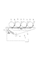
図6に示す画像形成装置は、像担持体として4つの感光体ドラム1a〜1dを備え、転写媒体としての中間転写ベルト(中間転写体)51を備えたフルカラー電子写真画像形成装置である。感光体ドラム1a〜1dの周囲には帯電器2a〜2d、露光装置3a〜3d、現像装置4a〜4d、感光体クリーナ6a〜6d等が配置され、それぞれが画像形成手段たるプロセスユニットPa〜Pdを構成する。各プロセスユニットにてイエロー、マゼンタ、シアン、ブラックの各色の画像が形成された感光体ドラム1上の画像(現像剤像)は、感光体ドラム1に接触して移動通過する中間転写ベルト51上に一次転写部N1において順次一次転写され、中間転写ベルト51上に転写された画像は、さらに二次転写部N2において紙等の転写材へ二次転写される構成となっている。
The image forming apparatus shown in FIG. 6 is a full-color electrophotographic image forming apparatus that includes four
各プロセスユニットは同一構成のため、プロセスユニットPaを例にとって、各要素につき符号a〜dを省略して説明する。画像形成手段たるプロセスユニットPには、像担持体の例としての感光体ドラム1が配置されており、感光体ドラム1は矢印方向に回転自在となっている。さらに、感光体ドラム1の周囲には、一次帯電手段としての帯電器2、露光装置3、現像装置4、そして、感光体クリーナ(第一回収手段)6が感光体ドラム1の回転方向に沿って順次配設されている。なお、画像形成において感光体ドラム1に作用する各プロセス手段は、不図示の制御手段により制御される。
Since each process unit has the same configuration, the process unit Pa will be described as an example, omitting the symbols a to d for each element. In the process unit P, which is an image forming unit, a
図7に示すように、感光体ドラム1は、アルミニウム等の導電性基体11と、その外周に形成された光導電層12を基本構成とする円筒状の電子写真感光体ドラムである。その中心には支軸を有し、この支軸を中心として矢印R1方向に、プロセススピード(Ps)300mm/sで回転駆動されるようになっている。
As shown in FIG. 7, the
感光体ドラム1の上方には、帯電器2が配置されている。帯電器2はワイヤー21、グリッド22、シールド部材23より構成され、感光体ドラム1表面に5mmの距離を持って配置されており、この表面を所定の極性、電位に一様均一に帯電する。詳しくは、不図示の電源によって、ワイヤー21には定電流制御で1mAの電流が印加され、グリッド22には定電圧制御で-720V電圧が印加される。これにより、感光体ドラム1表面を-700V均一に帯電する。感光体ドラム1の回転方向における帯電器2の下流側には、露光装置3が配設されている。露光装置3は、画像データ(画像情報)に対応したレーザー光をOFF/ONしながら走査して、照射された感光体ドラム1の表面電位は-150Vなることで、静電潜像(静電像)が形成される。
A
露光装置3の下流側に配置された現像装置(現像手段)4は、トナー(現像剤)とキャリア(磁性体)から成る二成分現像剤を収容した現像容器41を有し、その現像容器41の感光体ドラム1に面した開口部内に現像スリーブ42が回転自在に設置され、現像スリーブ42内には現像スリーブ42上にトナーを担持させるマグネットローラ43が固定配置されている。現像容器41の現像スリーブ42の上方位置には、現像スリーブ42上に担持された現像剤を規制して薄層の現像剤層に形成する規制ブレード44が設置されている。さらに現像容器41内には、区画された現像室45及び攪拌室46が設けられ、そこには現像剤を攪拌、搬送するためのスクリュー45s、46sが設けられている。また、現像容器41の上方には補給用のトナーを収容した補給室47が設けられている。現像剤濃度検知手段49は透磁率を検知するセンサであり、攪拌室46、且つトナー補給が行なわれる開口の現像剤搬送方向の上流位置に設けられている。
The developing device (developing means) 4 disposed on the downstream side of the
薄層の現像剤層に形成されたトナーは、感光体ドラム1と対向した現像領域へ搬送されると、マグネットローラ43の現像領域に位置された現像主極の磁気力によって穂立ちし、磁気ブラシが形成される。この磁気ブラシで感光体ドラム1の面上を擦ると共に、現像スリーブ42に、不図示の電源によって-500Vの直流電圧と、周波数が120000HzでVp-pが1800Vの交流電圧が重畳して印加されることにより、磁気ブラシの穂を構成するキャリアに付着しているトナーが静電潜像の露光部に付着して現像し、感光体ドラム1上にトナー像が形成される。このように現像工程によって現像剤中のトナーが消費されるが、トナーが消費されると現像剤濃度検知手段49などで検知されるトナー濃度変化によって、補給室47から消費されたトナー量分の新しいトナーが補給される。このようにして画像濃度が一定に保たれる。
When the toner formed on the thin developer layer is transported to the development area facing the
現像装置4の下流側の感光体ドラム1の下方には、一次転写ローラ53が配設されている。一次転写ローラ53は、9.8mNの押圧力で中間転写ベルト51を介して感光体ドラム1表面に圧接され、感光体ドラム1と一次転写ローラ53との間には一次転写部N1が形成される。転写ニップ部には、中間転写ベルト51が挟まれており、不図示の電源から+1000Vの直流電圧で一次転写ローラ53を印加することによって、マイナスに帯電したトナーを、感光体ドラム1表面から中間転写ベルト51表面に転写させる。
A
トナー像転写後の感光体ドラム1は、感光体クリーナ6によって残留トナー等の付着物が除去される。感光体クリーナ6は、クリーニングブレード(ブレード部材)61及び搬送スクリュー62を備えている。感光体クリーナ6によって残留トナーが除去された感光体ドラムは、再び帯電工程に戻り、上述の一連の画像形成動作が繰返される。
After the toner image has been transferred, the
また図6に示すように、各感光体ドラム1の下方には、中間転写ユニット5が配設されている。中間転写ユニット5は、中間転写ベルト51及び一次転写ローラ(第一転写手段)53a〜53d、及び二次転写対向ローラ56、二次転写ローラ(第二転写手段)57、およびベルトクリーナ(第二回収手段)55を有している。ベルトクリーナ55は所定の電圧を印加したファーブラシなどにより構成することもできるが、本実施例においては弾性ブレードを用いた構成となっている。
Further, as shown in FIG. 6, an
感光体ドラム1上に形成された各色のトナー像は、上述のように一次転写部N1において順次中間転写ベルト51上に転写された後、中間転写ベルト51の回転とともに二次転写部N2まで搬送される。一方、このときまでに不図示の給送カセットから取り出された転写材Sが供給され、二次転写対向ローラ56と二次転写ローラ57の間に印加される二次転写バイアスによってトナー像が転写材S上に転写される。なお、中間転写ベルト51上の転写残トナー等は、ベルトクリーナ55によって除去、回収される。トナー像を転写された転写材Sは、不図示の定着手段によって加圧、加熱されることによりトナー像を溶融して定着され、転写材S上にフルカラー画像が形成される。
The toner images of the respective colors formed on the
本実施例で用いているトナーは、トナーとしてポリエステル樹脂より生成された平均粒径6μmのカラートナー粒子に、長さ平均粒径1μmのチタン酸ストロンチュウム粉体、及び、長さ平均粒径0.1μmの疎水性アルミナ微粉体が外添されているものを用いている。キャリアとしては平均粒径50μmのフェライトキャリアが用いられている。また、トナーはキャリアとの摺擦によって-25μC/mgにネガ帯電される。 The toner used in this example is a color toner particle having an average particle diameter of 6 μm produced from a polyester resin as a toner, a strontium titanate powder having a length average particle diameter of 1 μm, and a length average particle diameter The one to which 0.1 μm hydrophobic alumina fine powder is externally added is used. As the carrier, a ferrite carrier having an average particle diameter of 50 μm is used. The toner is negatively charged to -25 μC / mg by rubbing with the carrier.
[特徴的な動作]
次に、本実施例の特徴的な動作、すなわち画像形成のタイミングに応じて、中間転写ベルト51上の現像剤を、前記第二回収手段により回収するか、または前記像担持体を介して前記第一回収手段により回収するかの選択的動作について説明する。この選択的動作は、図6及び図2に示す決定手段70により行われる。図1は選択動作の制御のフローチャート、図2は転写残トナーの流れを説明する図、図3は一次転写部、二次転写部、ベルトクリーニング部におけるトナー像の移動を説明するタイミングチャート、図4は感光体ドラムとクリーニングブレードとの間のトルク推移を示す図である。
[Characteristic operation]
Next, the developer on the
ここで、本実施例においては、ベルトクリーナ55は中間転写ベルト51に対して離接可能な構成となっている。そして図2に示すように、ベルトクリーナ55を中間転写ベルト51に当接させれば、中間転写ベルト51上の転写残トナーは、ベルトクリーナ55によって回収される。ベルトクリーナ55と中間転写ベルト51との当接位置を、ベルトクリーニング部N3とする。
Here, in this embodiment, the
また図2において破線で示すように、中間転写ベルト51をベルトクリーナ55から離間させると、転写残トナーは一次転写部N1へと搬送される。このとき一次転写ローラ53に不図示の電源から例えば-1000Vの直流電圧を印加することによって、主にプラスに帯電している転写残トナーを中間転写ベルト51表面から感光体ドラム1表面に転写させることができる。なお、使用するトナーの帯電極性に応じて、一次転写ローラ53へのバイアスはプラスの場合もマイナスの場合もあり、トナーの特性によっては、転写バイアスを通常の画像形成時と回収時とで異なるものにする場合もある。感光体ドラム1に転写された転写残トナーは感光体クリーナ6によって回収されるため、これにより感光体ドラム1と感光体クリーナ6のクリーニングブレード61との間に、現像剤を供給することができる。
Further, as indicated by a broken line in FIG. 2, when the
中間転写ベルト51は循環(回動)するものであるから、先に画像形成した位置に次に画像形成する位置が重なる場合と、重ならない場合がある。すなわち二次転写部N2を通過した中間転写ベルト51上において先に画像形成されていた位置には転写残トナーが付着しており、この位置が一次転写部N1を通過するときに新たな現像剤が転写されるか否かが問題となる。感光体ドラム1から中間転写ベルト51へのトナー像転写と、中間転写ベルト51から感光体ドラム1へのトナー転写(回収)は、同時に行うことはできないからである。
Since the
図3は中間転写ベルト51上のトナー像を複数の転写材へ連続して転写する際の様子を示す。
FIG. 3 shows a state in which the toner image on the
図3に示す画像Aは、先に画像形成した位置が一次転写部N1において次に画像形成する位置と重ならない場合を示している。すなわち画像形成間隔が広い低スループット時、例えば片面、両面画像形成時や、JOB間隔が広く、感光体ドラムの回転時間が長い場合である。なお図3における時間軸は実際の時間に比例するものではなく、理解を容易とするために模式的に表されている。 An image A shown in FIG. 3 shows a case where the position where the image is formed first does not overlap the position where the image is formed next in the primary transfer portion N1. That is, when the image formation interval is wide and low throughput, for example, when forming single-sided or double-sided images, or when the JOB interval is wide and the rotation time of the photosensitive drum is long. Note that the time axis in FIG. 3 is not proportional to the actual time, but is schematically shown for easy understanding.
画像形成が開始されると(図1のS1)、一次転写部N1で中間転写ベルト51に転写された画像Aは、中間転写ベルト51により二次転写部N2に搬送され、転写材Sに転写される。このとき転写残トナーが発生し(図1のS2)、これを転写残Aトナーと称する。
When image formation is started (S1 in FIG. 1), the image A transferred to the
図1のS3において、転写残トナーのある位置が次に画像形成位置になるか否かを判断する。画像Aの場合においてはNOであるので、ベルトクリーナ55は中間転写ベルト51から離間し、転写残Aトナーを回収しない。中間転写ベルト51上の転写残Aトナーは一次転写部N1に至り、感光体ドラム1へと転写され(図1のS4)、感光体クリーナ6に回収される(図1のS5)。このようにして、二次転写残トナーを感光体ドラム1とクリーニングブレード61との間に供給することができる。
In S3 of FIG. 1, it is determined whether or not the position where the toner remaining after transfer is the next image forming position. Since NO in the case of image A, the
図3に示す画像Bは、先に画像形成した位置が一次転写部N1において次に画像形成する位置と重なる場合を示している。画像形成が開始され(図1のS1)、画像Bが一次転写部N1および二次転写部N2を経て転写材Sに転写されると、転写残Bトナーが発生する(図1のS2)。転写残トナーのある位置が次に画像形成位置になるか否かを判断すると(図1のS3)、画像Bの場合にはYESである。そこでベルトクリーナ55を中間転写ベルト51へと当接させ、ベルトクリーニング部N3において転写残Bトナーを回収する(図1のS6)。そして、一次転写部N1において当該位置に次の画像の一次転写を行う(図1のS7)。
An image B shown in FIG. 3 shows a case where the position where the image is formed first overlaps the position where the image is formed next in the primary transfer portion N1. When image formation is started (S1 in FIG. 1) and the image B is transferred to the transfer material S via the primary transfer portion N1 and the secondary transfer portion N2, transfer residual B toner is generated (S2 in FIG. 1). When it is determined whether or not the position where the toner remaining after transfer becomes the image forming position next (S3 in FIG. 1), YES is determined in the case of the image B. Therefore, the
図4は感光体ドラム1とクリーニングブレード61との間のトルク推移を示す図である。図からわかるように、二次転写残トナーを感光体クリーナ6に回収させると、トルク上昇が緩やかになることがわかる。すなわち、感光体ドラム1とクリーニングブレード61間のトルクが抑えられるため、これらにかかる負荷が軽減され、各々の耐久性を向上させることができる。
FIG. 4 is a diagram showing torque transition between the
また、本実施例の手法は、画像形成に一度使用されたトナーを有効活用する。従って、従来例にて説明した構成のように、本来の画像形成に必要ないトナーを使用しないため、無駄なトナー消費を抑えることができる。 Further, the method of this embodiment effectively uses the toner once used for image formation. Therefore, as in the configuration described in the conventional example, toner that is not necessary for original image formation is not used, and wasteful toner consumption can be suppressed.
なお、決定手段70は、具体的には画像形成装置の制御装置の一部によって担うことが好ましく、CPUやMPUなどの演算手段と、ROMなどに保存された制御プログラムによって実現される。そして一次転写ローラ53やベルトクリーナ55に対し、駆動制御などを介して間接的に、若しくはこれらに設けられたセンサに対して直接的に接続されて、本実施例に係る選択的動作を実行する。
Specifically, the
{第二実施例}
本発明にかかる画像形成装置の第二実施例について説明する。本実施例は、ベルトクリーナ55として、ベルトから離間可能な弾性ブレードに代えて、ブラシを用いて静電的に転写残トナーを回収する構成について説明する。
{Second Example}
A second embodiment of the image forming apparatus according to the present invention will be described. In this embodiment, a configuration in which the transfer residual toner is electrostatically collected using a brush instead of an elastic blade that can be separated from the belt as the
ブラシを用いたクリーナの場合、転写残トナーと逆極性のバイアスを印加することにより、転写残トナーを回収することができる。逆に、転写残トナーの極性と同じバイアスを印加することにより、ブラシに転写残トナーが回収されないようにすることができる。すると転写残トナーは、ベルトクリーナ55を通過して、そのまま一次転写部N1に搬送することができる。一次転写部N1では、転写残トナーが感光体ドラム1へ転写される極性のバイアスを印加する。中間転写ベルト51上のトナーの回収を、ベルトクリーナ55へ行うか、感光ドラム1へ行うかの決定は決定手段70により行う。
In the case of a cleaner using a brush, the transfer residual toner can be collected by applying a bias having a polarity opposite to that of the transfer residual toner. Conversely, by applying the same bias as that of the transfer residual toner, it is possible to prevent the transfer residual toner from being collected by the brush. Then, the transfer residual toner can pass through the
すなわち、ベルトクリーナ55として弾性ブレードを用いた場合には、クリーニングを行うか行わないかを選択するために、離接機構を必要とした。しかし、本実施例の構成にすることで、ベルトクリーナ55の機械的な離間動作を行わないので、画像形成部に与える振動による影響を軽減することができる。
That is, when an elastic blade is used as the
{第三実施例}
本発明にかかる画像形成装置の第三実施例について説明する。図5は本実施例に係る一次転写部、二次転写部、ベルトクリーニング部におけるトナー像の移動を説明するタイミングチャートであって、上記第一実施例と説明の重複する部分については同一の符号を付して説明を省略する。
{Third embodiment}
A third embodiment of the image forming apparatus according to the present invention will be described. FIG. 5 is a timing chart for explaining the movement of the toner image in the primary transfer unit, the secondary transfer unit, and the belt cleaning unit according to the present embodiment. The description is omitted.
上記第一実施例では、次の画像形成タイミングに応じて、前記転写媒体上の現像剤を、前記第二回収手段により回収するか、または前記像担持体を介して前記第一回収手段により回収するかの選択的動作をするよう説明した。これに対し本実施例は、基本的には中間転写ベルト51上の転写残トナーを常に感光体クリーナ6によって回収するものとし、次の画像形成のタイミングの方を変更するものである。
In the first embodiment, the developer on the transfer medium is collected by the second collection unit or collected by the first collection unit via the image carrier according to the next image formation timing. Explained to do selective action. In contrast, in this embodiment, basically, the transfer residual toner on the
図7のタイミングチャートにおいて、画像Aは先に画像形成した位置が一次転写部N1において次に画像形成する位置と重ならない場合、画像Bは重なる場合を示している。ここで、転写残Bトナーが一次転写部N1に至る場合には、図に二重枠にて示すように、次の画像形成を行わず、転写残Bトナーが感光体ドラム1に転写されるのを待ってから次の画像形成を行う。
In the timing chart of FIG. 7, the image A indicates a case where the position where the image is formed first does not overlap with the position where the next image is formed in the primary transfer portion N <b> 1, and the image B overlaps. Here, when the transfer residual B toner reaches the primary transfer portion N1, the transfer residual B toner is transferred to the
このように構成することにより、より多い頻度で感光体ドラム1とクリーニングブレード61との間にトナーを供給することができるため、感光体ドラム1のトルク推移をより低めにすることが可能となる。
With this configuration, since toner can be supplied between the
なお、通常は上記第一実施例に示す制御を行うことで生産性を維持し、トルク推移に応じてトナー供給が必要と判断された場合に第三実施例の制御を行うよう構成しても良い。これにより、生産性とトルク低減のバランスを図ることができる。 Normally, the control shown in the first embodiment may be performed to maintain productivity, and the control of the third embodiment may be performed when it is determined that toner supply is necessary according to the torque transition. good. Thereby, the balance between productivity and torque reduction can be achieved.
A、B…画像、N1…一次転写部、N2…二次転写部、N3…ベルトクリーニング部、P…プロセスユニット、S…転写材、1…感光体ドラム(像担持体)、2…帯電器、3…露光装置、4…現像装置、6…感光体クリーナ(第一回収手段)、11…導電性基体、12…光導電層、21…ワイヤー、22…グリッド、23…シールド部材、41…現像容器、42…現像スリーブ、43…マグネットローラ、44…規制ブレード、45…現像室、45s…スクリュー、46…攪拌室、46s…スクリュー、47…補給室、49…現像剤濃度検知手段、51…中間転写ベルト(中間転写体)、53…一次転写ローラ(第一転写手段)、55…ベルトクリーナ(第二回収手段)、56…二次転写対向ローラ、57…二次転写ローラ(第二転写手段)、62…搬送スクリュー、70…決定手段
A, B: Image, N1: Primary transfer unit, N2: Secondary transfer unit, N3: Belt cleaning unit, P: Process unit, S: Transfer material, 1: Photosensitive drum (image carrier), 2 ... Charger DESCRIPTION OF
Claims (2)
複数の記録材へトナー像の転写が連続して行われる際に、前記中間転写体上の転写残トナーを前記第二回収手段により回収する第一のモードと、画像形成間隔が前記第一のモードの画像形成間隔よりも長く、前記中間転写体上の転写残トナーを前記像担持体を介して前記第一回収手段により回収する第二のモードと、を実行可能で、トナー像が形成された前記中間転写体の領域が前記二次転写部を通過してから初めて前記一次転写部を通過するときに、前記像担持体上のトナー像が前記中間転写体へ転写される場合には、前記領域の転写残トナーを前記第二回収手段により回収し、トナー像が形成された前記中間転写体の領域が前記二次転写部を通過してから初めて前記一次転写部を通過するときに、前記像担持体上のトナー像が前記中間転写体へ転写されない場合には、前記領域の転写残トナーを前記像担持体を介して前記第一回収手段により回収するように制御する制御手段を有することを特徴とする画像形成装置。 An image carrier on which an electrostatic latent image is formed, a developing unit that develops the electrostatic latent image into a toner image, an intermediate transfer member that is rotatable and onto which the toner image is transferred, and a primary transfer unit Primary transfer means for transferring the toner image on the image carrier to the intermediate transfer body, first recovery means for collecting the transfer residual toner on the image carrier, and the intermediate transfer body at a secondary transfer portion. In an image forming apparatus comprising: a secondary transfer unit that transfers the toner image on the recording material; and a second collection unit that collects the transfer residual toner on the intermediate transfer member.
When toner images are continuously transferred to a plurality of recording materials, a first mode in which the transfer residual toner on the intermediate transfer member is collected by the second collecting unit, and an image forming interval is the first mode. A second mode in which the transfer residual toner on the intermediate transfer member is collected by the first collecting means via the image carrier, and a toner image is formed. When the toner image on the image carrier is transferred to the intermediate transfer member when the region of the intermediate transfer member passes through the primary transfer portion for the first time after passing through the secondary transfer portion, When the transfer residual toner in the region is collected by the second collecting means, and the region of the intermediate transfer body on which the toner image is formed passes through the primary transfer unit for the first time after passing through the secondary transfer unit, The toner image on the image carrier is transferred to the intermediate transfer. If not transferred to the body, the image forming apparatus characterized by comprising control means for controlling the transfer residual toner of the region to recover by the first collecting unit via the image bearing member.
Priority Applications (1)
| Application Number | Priority Date | Filing Date | Title |
|---|---|---|---|
| JP2005350952A JP4963355B2 (en) | 2004-12-13 | 2005-12-05 | Image forming apparatus |
Applications Claiming Priority (3)
| Application Number | Priority Date | Filing Date | Title |
|---|---|---|---|
| JP2004359594 | 2004-12-13 | ||
| JP2004359594 | 2004-12-13 | ||
| JP2005350952A JP4963355B2 (en) | 2004-12-13 | 2005-12-05 | Image forming apparatus |
Publications (3)
| Publication Number | Publication Date |
|---|---|
| JP2006195438A JP2006195438A (en) | 2006-07-27 |
| JP2006195438A5 JP2006195438A5 (en) | 2009-01-22 |
| JP4963355B2 true JP4963355B2 (en) | 2012-06-27 |
Family
ID=36801534
Family Applications (1)
| Application Number | Title | Priority Date | Filing Date |
|---|---|---|---|
| JP2005350952A Expired - Fee Related JP4963355B2 (en) | 2004-12-13 | 2005-12-05 | Image forming apparatus |
Country Status (1)
| Country | Link |
|---|---|
| JP (1) | JP4963355B2 (en) |
Families Citing this family (2)
| Publication number | Priority date | Publication date | Assignee | Title |
|---|---|---|---|---|
| US7398032B2 (en) * | 2004-12-13 | 2008-07-08 | Canon Kabushiki Kaisha | Image forming apparatus featuring first and second cleaners operable on the basis of an interval of an image forming process during a continuous image forming process |
| JP5409574B2 (en) * | 2010-09-29 | 2014-02-05 | 京セラドキュメントソリューションズ株式会社 | Image forming apparatus |
Family Cites Families (4)
| Publication number | Priority date | Publication date | Assignee | Title |
|---|---|---|---|---|
| JPH04296785A (en) * | 1991-03-26 | 1992-10-21 | Canon Inc | Image forming device |
| JPH09197763A (en) * | 1996-01-12 | 1997-07-31 | Canon Inc | Image forming device |
| JP2000187396A (en) * | 1998-12-21 | 2000-07-04 | Canon Inc | Image forming device |
| JP4143372B2 (en) * | 2002-09-27 | 2008-09-03 | キヤノン株式会社 | Image forming apparatus |
-
2005
- 2005-12-05 JP JP2005350952A patent/JP4963355B2/en not_active Expired - Fee Related
Also Published As
| Publication number | Publication date |
|---|---|
| JP2006195438A (en) | 2006-07-27 |
Similar Documents
| Publication | Publication Date | Title |
|---|---|---|
| JP5053602B2 (en) | Image forming apparatus | |
| JP2014130362A (en) | Image forming apparatus and image forming method | |
| JP2007225834A (en) | Image forming apparatus | |
| JP6098408B2 (en) | Image forming apparatus | |
| JP2017009913A (en) | Image forming apparatus | |
| JP4939187B2 (en) | Image forming apparatus | |
| JP4963355B2 (en) | Image forming apparatus | |
| JP2004029209A (en) | Image forming apparatus | |
| JP5284333B2 (en) | Image forming apparatus | |
| JP2007264398A (en) | Image forming apparatus | |
| JP5268328B2 (en) | Image forming apparatus | |
| JP5517390B2 (en) | Image forming apparatus and image forming method | |
| US7398032B2 (en) | Image forming apparatus featuring first and second cleaners operable on the basis of an interval of an image forming process during a continuous image forming process | |
| JP4516771B2 (en) | Image forming apparatus | |
| JP2011232477A (en) | Belt device and image forming apparatus | |
| JP5404324B2 (en) | Image forming apparatus | |
| JP5232612B2 (en) | Image forming apparatus | |
| JP2009151122A (en) | Image forming apparatus | |
| JPH06186898A (en) | Image forming device | |
| JP2007233276A (en) | Image recording apparatus | |
| JP2002323803A (en) | Image forming device | |
| JP5535372B2 (en) | Image forming apparatus | |
| JP2006171358A (en) | Image forming apparatus | |
| CN112099322B (en) | Image forming apparatus having a plurality of image forming units | |
| JP2001305878A (en) | Image forming apparatus |
Legal Events
| Date | Code | Title | Description |
|---|---|---|---|
| RD02 | Notification of acceptance of power of attorney |
Free format text: JAPANESE INTERMEDIATE CODE: A7422 Effective date: 20080116 |
|
| A521 | Written amendment |
Free format text: JAPANESE INTERMEDIATE CODE: A523 Effective date: 20081203 |
|
| A621 | Written request for application examination |
Free format text: JAPANESE INTERMEDIATE CODE: A621 Effective date: 20081203 |
|
| A977 | Report on retrieval |
Free format text: JAPANESE INTERMEDIATE CODE: A971007 Effective date: 20110203 |
|
| A131 | Notification of reasons for refusal |
Free format text: JAPANESE INTERMEDIATE CODE: A131 Effective date: 20110208 |
|
| A521 | Written amendment |
Free format text: JAPANESE INTERMEDIATE CODE: A523 Effective date: 20110408 |
|
| A131 | Notification of reasons for refusal |
Free format text: JAPANESE INTERMEDIATE CODE: A131 Effective date: 20110830 |
|
| A521 | Written amendment |
Free format text: JAPANESE INTERMEDIATE CODE: A523 Effective date: 20111003 |
|
| TRDD | Decision of grant or rejection written | ||
| A01 | Written decision to grant a patent or to grant a registration (utility model) |
Free format text: JAPANESE INTERMEDIATE CODE: A01 Effective date: 20120321 |
|
| A01 | Written decision to grant a patent or to grant a registration (utility model) |
Free format text: JAPANESE INTERMEDIATE CODE: A01 |
|
| A61 | First payment of annual fees (during grant procedure) |
Free format text: JAPANESE INTERMEDIATE CODE: A61 Effective date: 20120323 |
|
| FPAY | Renewal fee payment (event date is renewal date of database) |
Free format text: PAYMENT UNTIL: 20150406 Year of fee payment: 3 |
|
| LAPS | Cancellation because of no payment of annual fees |