JP4962005B2 - Steel manufacturing method, steel cooling control device, and steel manufacturing device - Google Patents
Steel manufacturing method, steel cooling control device, and steel manufacturing device Download PDFInfo
- Publication number
- JP4962005B2 JP4962005B2 JP2006356780A JP2006356780A JP4962005B2 JP 4962005 B2 JP4962005 B2 JP 4962005B2 JP 2006356780 A JP2006356780 A JP 2006356780A JP 2006356780 A JP2006356780 A JP 2006356780A JP 4962005 B2 JP4962005 B2 JP 4962005B2
- Authority
- JP
- Japan
- Prior art keywords
- temperature
- steel
- cooling
- transformation
- steel plate
- Prior art date
- Legal status (The legal status is an assumption and is not a legal conclusion. Google has not performed a legal analysis and makes no representation as to the accuracy of the status listed.)
- Active
Links
Images


Description
本発明は、熱間圧延鋼板の製造方法として適用可能な鋼材の製造方法、熱間圧延鋼板を冷却する冷却装置の動作を制御する制御装置として適用可能な鋼材の冷却制御装置、及び、当該冷却制御装置を備える鋼材の製造装置に関する。より具体的には、鋼板温度を高精度に制御することが可能な、鋼材の製造方法、鋼材の冷却制御装置、及び、当該冷却制御装置を備える鋼材の製造装置に関する。 The present invention relates to a steel manufacturing method applicable as a method of manufacturing a hot rolled steel plate, a steel cooling control device applicable as a control device for controlling the operation of a cooling device for cooling the hot rolled steel plate, and the cooling The present invention relates to a steel material manufacturing apparatus including a control device. More specifically, the present invention relates to a steel material manufacturing method, a steel material cooling control device, and a steel material manufacturing device including the cooling control device capable of controlling a steel plate temperature with high accuracy.
熱間圧延設備では、仕上圧延機で圧延された高温の鋼板を、搬送テーブルに設置された冷却装置で冷却した後、巻取装置で巻取り、コイルにする。鋼板の機械特性を所定の範囲に収め、良好な品質を得るためには、巻取装置前の巻取温度の管理が重要となる。 In a hot rolling facility, a high-temperature steel plate rolled by a finish rolling mill is cooled by a cooling device installed on a transfer table, and then wound by a winding device to form a coil. In order to keep the mechanical properties of the steel sheet within a predetermined range and obtain good quality, it is important to manage the winding temperature before the winding device.
仕上圧延機で圧延された鋼板は、仕上圧延機の出側に設置された仕上出口温度計を通過する際に表面温度が測定され、さらに、板厚が測定される。このとき、鋼板の表面温度(鋼板温度)や板厚、鋼板の搬送速度、鋼板の比熱、熱伝導率、及び密度、冷却装置から鋼板へと放出される冷却媒体(例えば、工業用水等)の量(以下、「水量」という。)及び温度、並びに、気温を用いて、冷却装置によって冷却された後の鋼板温度(巻取装置によって巻き取られる前の温度(以下、「巻取温度」という。))が予測される。ここで、予測された巻取温度が目標温度と一致しない場合には、制御装置によって冷却装置の動作が調整され(具体的には、水量調整バルブの設定変更を行い)、予測された巻取温度と目標温度とを一致させる制御が行なわれる。そして、鋼板が搬送テーブル上にある間に、(1)仕上出口温度計による表面温度の測定、(2)冷却装置によって冷却された後の鋼板温度の予測、及び、(3)冷却装置の動作制御が、0.4〜2.0秒程度の周期で行なわれる。 The steel sheet rolled by the finishing mill is measured for the surface temperature when passing through a finishing outlet thermometer installed on the exit side of the finishing rolling mill, and the plate thickness is further measured. At this time, the surface temperature (steel plate temperature) and thickness of the steel plate, the conveying speed of the steel plate, the specific heat of the steel plate, the thermal conductivity, and the density of the cooling medium (for example, industrial water) released from the cooling device to the steel plate Steel sheet temperature after cooling by the cooling device (hereinafter referred to as “winding temperature”) using the amount (hereinafter referred to as “water amount”) and temperature, and air temperature. .)) Is predicted. Here, when the predicted winding temperature does not coincide with the target temperature, the operation of the cooling device is adjusted by the control device (specifically, the setting of the water amount adjustment valve is changed), and the predicted winding temperature is adjusted. Control for matching the temperature with the target temperature is performed. And while the steel plate is on the transfer table, (1) measurement of the surface temperature by the finishing outlet thermometer, (2) prediction of the steel plate temperature after being cooled by the cooling device, and (3) operation of the cooling device Control is performed at a cycle of about 0.4 to 2.0 seconds.
このような制御方法において、巻取温度の予測精度を向上させるためには、仕上圧延機から巻取装置までの温度予測計算を高精度に行なうことが必要とされる。温度予測計算を高精度に行なうためには、冷却装置から放出される冷却媒体によって冷却(水冷)される箇所から放出される熱量(以下、「水冷抜熱量」という。)、及び、空冷される箇所から放出される熱量(以下、「空冷抜熱量」という。)に加え、鋼の相変態進行中に発生する発熱量(以下、「変態発熱量」という。)を、限られた時間内で正確に予測することが必要とされる。 In such a control method, in order to improve the prediction accuracy of the winding temperature, it is necessary to perform temperature prediction calculation from the finishing mill to the winding device with high accuracy. In order to perform the temperature prediction calculation with high accuracy, the amount of heat released from the portion cooled (water-cooled) by the cooling medium released from the cooling device (hereinafter referred to as “water-cooled heat removal amount”) and air-cooled. In addition to the amount of heat released from the location (hereinafter referred to as “air-cooled heat removal amount”), the amount of heat generated during the phase transformation of the steel (hereinafter referred to as “transformation heat generation amount”) within a limited time. Accurate prediction is required.
通常、仕上圧延後の鋼板温度は800〜900℃であり、巻取温度は400〜700℃であるところ、鋼の相変態は700〜800℃で始まり、変態が終了するまでの変態発熱量は、鋼板温度を50〜120℃程度上昇させる熱量であるため、冷却中における変態発熱量を正確に予測することは極めて重要である。 Usually, the steel plate temperature after finish rolling is 800 to 900 ° C., the coiling temperature is 400 to 700 ° C., the phase transformation of steel starts at 700 to 800 ° C., and the transformation calorific value until the transformation is finished is Since it is the amount of heat that raises the steel sheet temperature by about 50 to 120 ° C., it is very important to accurately predict the transformation heat generation amount during cooling.
仕上圧延機で圧延され冷却装置で冷却された鋼板の巻取温度を制御する技術は、これまでにいくつか開示されてきている。例えば、特許文献1には、ホットストリップミルで熱間圧延した熱延鋼材である鋼帯(S)を制御冷却するに当たり、前記鋼帯(S)の温度を少なくとも冷却設備(R)の入側と出側とで測定し、該測定温度差値に基づいて逐次最小二乗法を用いて、前記鋼帯(S)の水冷時における上部水冷部(3a)の各冷却バンクでの上面の熱伝達係数に関する学習項aiの学習値、および下部水冷部(3b)の各冷却バンクでの下面の熱伝達係数に関する学習項biの学習値、そして空冷時における上下各冷却バンクでの上下面の熱伝達係数に関する学習項ciの学習値を求め、該各学習値と冷却設備(R)による目標温度降下量ΔTとより各冷却バンクでの温度降下量ΔTiを求め、各冷却バンクでの温度降下量が前記温度降下量ΔTiとなるよう冷却制御する熱延鋼材の温度制御方法が開示されている。
Several techniques for controlling the coiling temperature of a steel sheet that has been rolled by a finish mill and cooled by a cooling device have been disclosed. For example, in
また、変態発熱量を予測する技術として、特許文献2には、冷却設備1Aを通過する鋼板Sを、鋼板の通過速度データ(速度検出器5A、5A’)、冷却設備1Aの入り側、出側での鋼材の温度データ(温度計6A、6A’)、鋼材の変態領域における発熱量等のデータに基づく温度学習制御により冷却する、熱延鋼材の冷却制御方法が開示されている。また、特許文献3には、熱間圧延された鋼材を所定の目標温度に正確に冷却する際に用いるのに好適な、鋼材の冷却制御方法が開示されている。
Further, as a technique for predicting the transformation heat generation amount,
さらに、特許文献4には、変態発熱モデルを簡略化することで計算を容易にし、圧延材の冷却モデルと分離し、変態発熱モデル単独で学習することにより、圧延材の巻取温度をより高精度に制御することができる巻取温度制御装置が開示されている。
しかし、特許文献1に開示されている技術では、鋼板の温度変化に大きな影響を及ぼす変態発熱量が考慮されていないため、巻取温度の予測精度が低下しやすいという問題があった。また、特許文献2に開示されている技術では、変態開始温度を予め求めているが、冷却中の変態開始温度は鋼板を圧延してから変態開始に至るまでの冷却過程の差異によって変化することが広く知られているため、かかる技術によっても、巻取温度の予測精度が低下しやすいという問題があった。また、特許文献3では、多種多様な鋼板の巻取温度を予測するために、膨大な量のパラメータを用意する必要があるため、現実的には、適用範囲が極めて限定されるという問題があった。さらに、特許文献4に開示されている技術では、変態発熱量の予測精度が低く、巻取温度の予測精度が低下しやすいという問題があった。
However, the technique disclosed in
ここで、上述のように、冷却される鋼板を所定の温度に制御するためには、水冷抜熱量及び空冷抜熱量に加え、鋼板内部で発生する変態発熱量を短時間で精度良く予測することが必要である。ところが、特許文献2や特許文献4に開示されているような、変態発熱量を予測する従来のモデルでは、鋼板の添加元素成分やサイズの異なる多様な鋼板に対応することが困難であり、特に、他の鋼種よりも相変態が低温で生じる高炭素鋼では、変態発熱量を予測することが困難であるという問題があった。
Here, as described above, in order to control the steel sheet to be cooled to a predetermined temperature, in addition to the water-cooled heat release amount and air-cooled heat release amount, the transformation heat generation amount generated inside the steel plate should be accurately predicted in a short time. is required. However, in the conventional model that predicts the transformation calorific value as disclosed in
そこで、本発明は、巻取温度に代表される鋼板温度の予測精度を向上させて鋼板温度を高精度に制御することが可能な、鋼材の製造方法、鋼材の冷却制御装置、及び、当該冷却制御装置を備える鋼材の製造装置を提供することを課題とする。 Accordingly, the present invention provides a steel material manufacturing method, a steel material cooling control device, and a cooling device capable of controlling the steel sheet temperature with high accuracy by improving the prediction accuracy of the steel sheet temperature represented by the coiling temperature. It aims at providing the manufacturing apparatus of steel materials provided with a control apparatus.
本発明者らは、鋭意研究の結果、冷却装置によって連続的に冷却されている鋼板の変態発熱挙動を、等温変態線図(以下、「TTT曲線図」ということがある。)を用いた変態発熱挙動予測モデルを用いることで、従来の変態発熱量予測モデルにおいて必要とされた膨大な量のパラメータを用意することなく、容易に変態発熱予測が可能となることを見出した。さらに、TTT曲線図を用いた変態発熱挙動予測モデルによって算出された変態発熱量に基いて、水冷抜熱量及び空冷抜熱量を調整することにより、鋼板温度を高精度に予測可能であることを見出した。加えて、鋼板の成分によって一意に決まるTTT曲線図を、冷却装置によって冷却される鋼板の組成に応じて変形させることにより、TTT曲線図が存在する組成と異なる組成の鋼板に対しても、変態発熱予測が可能であることを見出した。このようにして予測した変態発熱量に基いて、水冷抜熱量及び空冷抜熱量を調整すれば、TTT曲線図と異なる組成の鋼板であっても、その鋼板温度を高精度に予測可能である。 As a result of diligent research, the present inventors have investigated the transformation heat generation behavior of a steel sheet continuously cooled by a cooling device using an isothermal transformation diagram (hereinafter sometimes referred to as “TTT curve diagram”). By using the heat generation behavior prediction model, it has been found that the transformation heat generation prediction can be easily performed without preparing an enormous amount of parameters required in the conventional transformation heat generation amount prediction model. Furthermore, it has been found that the steel plate temperature can be predicted with high accuracy by adjusting the water-cooled heat removal amount and the air-cooled heat removal amount based on the transformation heat generation amount calculated by the transformation heat generation behavior prediction model using the TTT curve diagram. It was. In addition, by transforming the TTT curve diagram uniquely determined by the components of the steel plate according to the composition of the steel plate cooled by the cooling device, even a steel plate having a composition different from the composition in which the TTT curve diagram exists is transformed. It was found that fever prediction is possible. By adjusting the water-cooled heat removal amount and air-cooled heat removal amount based on the transformation heat generation amount thus predicted, the steel plate temperature can be predicted with high accuracy even for a steel plate having a composition different from that of the TTT curve diagram.
本発明は、上記知見に基いてなされたものであり、TTT曲線図を用いて算出した変態発熱量を用いて鋼板温度を予測することを、その要旨とする。 The present invention has been made on the basis of the above findings, and its gist is to predict the steel sheet temperature using the transformation heat value calculated using the TTT curve diagram.
以下、本発明について説明する。なお、本発明の理解を容易にするため、添付図面の参照符号を括弧書きにて付記するが、それにより本発明が図示の形態に限定されるものではない。 The present invention will be described below. In order to facilitate understanding of the present invention, reference numerals in the accompanying drawings are appended in parentheses, but the present invention is not limited to the illustrated embodiments.
第1の本発明は、仕上圧延機(2)で加工された鋼板(1)を、冷却手段(5)で冷却する工程を経て製造される、鋼材の製造方法であって、冷却手段によって冷却される前の鋼板の温度を測定する、第1温度測定工程と、鋼板の表面から放出される熱量の総和を算出する、熱量算出工程と、等温変態線図を用いて鋼板の変態発熱量を算出する、変態発熱量算出工程と、第1温度測定工程によって測定された温度と、熱量算出工程によって算出された熱量と、変態発熱量算出工程によって算出された変態発熱量と、を用いて、冷却手段で冷却された鋼板の温度を予測する、温度予測工程と、冷却手段によって冷却された鋼板の冷却温度を測定する、第2温度測定工程と、温度予測工程によって予測された温度と、第2温度測定工程によって測定された冷却温度とが一致するように、冷却手段の動作を制御する、動作制御工程と、を備え、さらに、鋼板の組成と、等温変態線図によって等温変態挙動が把握される鋼材の組成とが異なる場合に、鋼板の板厚、又は、鋼板の板厚及び鋼板に含有される元素の濃度、をパラメータとして有する関数を用いて、等温変態線図を変形する、等温変態線図変形工程を有し、等温変態線図変形工程によって変形された等温変態線図を用いて、変態発熱量算出工程において鋼板の変態発熱量が算出されることを特徴とする、鋼材の製造方法である。
1st this invention is a manufacturing method of the steel materials manufactured through the process of cooling the steel plate (1) processed with the finish rolling mill (2) with the cooling means (5), Comprising: It cools with a cooling means The temperature of the steel plate before being measured, the first temperature measurement step, the total amount of heat released from the surface of the steel plate, the calorie calculation step, and the transformation heat value of the steel plate using the isothermal transformation diagram Using the transformation calorific value calculation step, the temperature measured by the first temperature measurement step, the calorific value calculated by the calorific value calculation step, and the transformation calorific value calculated by the transformation calorific value calculation step, Predicting the temperature of the steel sheet cooled by the cooling means, measuring the cooling temperature of the steel sheet cooled by the cooling means, measuring the cooling temperature of the steel sheet cooled by the cooling means, temperature predicted by the temperature prediction process, 2Measured by temperature measurement process And so that the cooling temperature is matched to the controls the operation of the cooling means includes an operation control step, a further, the composition of the steel sheet, the composition of the steel isothermal transformation behavior is grasped by the isothermal transformation diagram The isothermal transformation diagram transformation step for transforming the isothermal transformation diagram using a function having as parameters the plate thickness of the steel plate or the plate thickness of the steel plate and the concentration of the element contained in the steel plate. has, with isothermal transformation diagram is deformed by isothermal transformation diagram deformation step, transformation calorific value of the steel sheet in the transformation calorific value calculation step is characterized Rukoto calculated, a method for producing steel.
第1の本発明、及び、以下に示す本発明(以下、これらをまとめて単に「本発明」という。)において、「冷却手段」は、鋼板に向けて冷却媒体を放出することにより、仕上圧延機によって加工された鋼板を冷却し得る手段であれば特に限定されるものではない。本発明における冷却手段としては、工業用水等の冷却水を放出することにより鋼板を冷却する冷却装置を例示することができる。さらに、本発明において、「鋼板の表面から放出される熱量の総和」とは、水冷抜熱量と空冷抜熱量との和を意味し、「等温変態線図を用いて鋼板の変態発熱量を算出する」とは、TTT曲線図に基いて導出される変態率を時間微分して得られる量に、変態潜熱を乗ずることによって、変態発熱量を算出することを意味する。ここで、「変態潜熱」は、鋼板の組成に対応して一意に定まる物理量であり、市販されている計算ソフト(例えば、Thermo−Calc等)を用いて算出することができる。 In the first invention and the invention shown below (hereinafter collectively referred to simply as “the present invention”), the “cooling means” is finished rolling by discharging the cooling medium toward the steel plate. There is no particular limitation as long as it is a means capable of cooling the steel sheet processed by the machine. As a cooling means in this invention, the cooling device which cools a steel plate by discharging | emitting cooling water, such as industrial water, can be illustrated. Furthermore, in the present invention, “the total amount of heat released from the surface of the steel sheet” means the sum of the amount of heat extracted from water cooling and the amount of heat extracted from air cooling. “Yes” means that the amount of heat generated by transformation is calculated by multiplying the amount obtained by time differentiation of the transformation rate derived based on the TTT curve diagram by the latent heat of transformation. Here, “transformation latent heat” is a physical quantity uniquely determined corresponding to the composition of the steel sheet, and can be calculated using commercially available calculation software (for example, Thermo-Calc).
本発明において、「鋼板の組成」とは、仕上圧延機で加工された後に、冷却手段で冷却される鋼板の組成を意味する。さらに、本発明において、「鋼板の板厚」とは、仕上圧延機によって加工された鋼板(冷却手段によって冷却される前の鋼板)の板厚を意味する。加えて、本発明において、「前記鋼板の板厚、又は、前記鋼板の板厚及び前記鋼板に含有される元素の濃度をパラメータとして有する関数を用いて、前記等温変態線図を変形する」とは、鋼板の板厚のみをパラメータとして有する関数、又は、鋼板の板厚と、鋼板に含有される鉄以外の元素の濃度とをパラメータとして有する関数に、上記板厚のデータ、又は、上記板厚のデータ及び鋼板に含有される鉄以外の元素の濃度データ、を代入して算出される値に応じて、TTT曲線図を温度−時間平面上で平行移動させることを意味する。 In the present invention, “the composition of the steel sheet” means the composition of the steel sheet that is processed by the finishing mill and then cooled by the cooling means. Furthermore, in the present invention, the “thickness of the steel plate” means the thickness of the steel plate processed by the finish rolling mill (the steel plate before being cooled by the cooling means). In addition, in the present invention, “the thickness of the steel plate, or the function having the plate thickness of the steel plate and the concentration of the element contained in the steel plate as a parameter is used to transform the isothermal transformation diagram”. Is a function having only the plate thickness of the steel plate as a parameter, or a function having as parameters the plate thickness of the steel plate and the concentration of an element other than iron contained in the steel plate, or the plate thickness data or the plate This means that the TTT curve diagram is translated on the temperature-time plane according to the value calculated by substituting the thickness data and the concentration data of elements other than iron contained in the steel plate.
また、上記第1の本発明において、鋼板が、JIS G4051:2005 機械構造用炭素鋼鋼材で規定される、S33C、S35C、S38C、S40C、S43C、S45C、S48C、S50C、S53C、S55C、及び、S58C、並びに、JIS G4401:2006 炭素工具鋼鋼材で規定される、SK90、SK85、SK80、SK75、SK70、SK65、及び、SK60からなる群(以下において、「鋼板選択群」ということがある。)より選択されることが好ましい。 In the first aspect of the present invention, the steel plate is defined by JIS G4051: 2005 carbon steel for machine structure, S33C, S35C, S38C, S40C, S43C, S45C, S48C, S50C, S53C, S55C, and S58C, and JIS G4401: 2006 A group consisting of SK90, SK85, SK80, SK75, SK70, SK65, and SK60 defined by carbon tool steel (hereinafter sometimes referred to as “steel plate selection group”). More preferably, it is selected.
第2の本発明は、仕上圧延機(2)で加工された鋼板(1)を冷却する冷却手段(5)の動作を制御する、鋼材の冷却制御装置(10)であって、冷却手段によって冷却される前の鋼板の温度を測定する、第1温度測定手段(4)と、鋼板の表面から放出される熱量の総和を算出する、熱量算出手段(11)と、等温変態線図を用いて鋼板の変態発熱量を算出する、変態発熱量算出手段(11)と、第1温度測定手段によって測定された温度と、熱量算出手段によって算出された熱量と、変態発熱量算出手段によって算出された変態発熱量とを用いて、冷却手段で冷却された鋼板の温度を予測する、温度予測手段(11)と、冷却手段によって冷却された鋼板の冷却温度を測定する、第2温度測定手段(6)と、温度予測手段によって予測された温度と、第2温度測定手段によって測定された冷却温度とが一致するように、冷却手段の動作を制御する、制御手段(11)と、鋼板の組成と、等温変態線図によって等温変態挙動が把握される鋼材の組成とが異なる場合に、鋼板の板厚、又は、鋼板の板厚及び鋼板に含有される元素の濃度、をパラメータとして有する関数を用いて、等温変態線図を変形する、等温変態線図変形手段(11)と、を備え、等温変態線図変形手段によって変形された等温変態線図を用いて、変態発熱量算出手段によって鋼板の変態発熱量が算出されることを特徴とする、鋼材の冷却制御装置である。
The second aspect of the present invention is a steel material cooling control device (10) for controlling the operation of the cooling means (5) for cooling the steel plate (1) processed by the finish rolling mill (2). First temperature measuring means (4) for measuring the temperature of the steel sheet before being cooled, calorific value calculating means (11) for calculating the total amount of heat released from the surface of the steel sheet, and an isothermal transformation diagram are used. The transformation calorific value calculating means (11) for calculating the transformation calorific value of the steel sheet, the temperature measured by the first temperature measuring means, the calorie calculated by the calorie calculating means, and the transformation calorific value calculating means are calculated. The temperature predicting means (11) for predicting the temperature of the steel sheet cooled by the cooling means using the transformation heat generation amount, and the second temperature measuring means for measuring the cooling temperature of the steel sheet cooled by the cooling means ( 6) and predicted by the temperature prediction means And temperature, such that the cooling temperature measured by the second temperature measuring means coincide, to control the operation of the cooling means, the control means (11), the composition of the steel sheet, isothermal transformation behavior by isothermal transformation diagram When the composition of the steel material is different, the isothermal transformation diagram is transformed using a function having as parameters the plate thickness of the steel plate or the plate thickness of the steel plate and the element concentration contained in the steel plate. , the isothermal transformation diagram deforming means (11) includes a, with the isothermal transformation diagram is deformed by isothermal transformation diagram deforming means, the Rukoto transformation calorific value of the steel sheet is calculated by the transformation calorific value calculation means This is a steel material cooling control device.
第2の本発明において、第1温度測定手段は、冷却手段によって冷却される前の鋼板の温度(例えば、800〜900℃程度の温度)を測定可能なものであれば、その形態は特に限定されるものではなく、熱間圧延鋼板の製造ラインで使用される温度計等を好適に用いることができる。 In the second aspect of the present invention, the form of the first temperature measuring means is particularly limited as long as the temperature of the steel sheet before being cooled by the cooling means can be measured (for example, a temperature of about 800 to 900 ° C.). However, a thermometer or the like used in a production line for hot rolled steel sheets can be suitably used.
また、上記第2の本発明において、鋼板が、JIS G4051:2005 機械構造用炭素鋼鋼材で規定される、S33C、S35C、S38C、S40C、S43C、S45C、S48C、S50C、S53C、S55C、及び、S58C、並びに、JIS G4401:2006 炭素工具鋼鋼材で規定される、SK90、SK85、SK80、SK75、SK70、SK65、及び、SK60からなる群(以下において、「鋼板選択群」ということがある。)より選択されることが好ましい。 In the second aspect of the present invention, the steel plate is defined by JIS G4051: 2005 carbon steel for machine structure, S33C, S35C, S38C, S40C, S43C, S45C, S48C, S50C, S53C, S55C, and S58C, and JIS G4401: 2006 A group consisting of SK90, SK85, SK80, SK75, SK70, SK65, and SK60 (hereinafter sometimes referred to as “steel plate selection group”) defined by carbon tool steel. More preferably, it is selected.
第3の本発明は、仕上圧延機(2)と、仕上圧延機によって加工された鋼板(1)を冷却可能な、冷却手段(5)と、上記第2の本発明にかかる鋼板の冷却制御装置(10)と、を備えることを特徴とする、鋼材の製造装置(100)である。 The third aspect of the present invention is a finish rolling mill (2), a cooling means (5) capable of cooling the steel sheet (1) processed by the finish rolling mill, and the cooling control of the steel sheet according to the second aspect of the present invention. An apparatus (100) for manufacturing a steel material, comprising: an apparatus (10).
第1の本発明によれば、TTT曲線図を用いることにより、膨大な量のパラメータを用いずに鋼板(1)の変態発熱量を高精度に予測することができるので、このようにして予測された変態発熱量と、水冷抜熱量と、空冷抜熱量を用いることで、鋼板温度を高精度に予測することが可能になる。そして、第1の本発明によれば、高精度に予測された鋼板温度と、測定された冷却温度とが一致するように、冷却手段(5)の動作が制御されるので、鋼板温度を高精度に制御することが可能な、鋼材の製造方法を提供することができる。さらに、第1の本発明において、冷却される鋼板(1)の組成と、TTT曲線図により等温変態挙動が把握される鋼材の組成とが異なる場合に、変形したTTT曲線図を用いて変態発熱量を算出することにより、鋼板の組成とTTT曲線図における組成とが異なる場合であっても、鋼板温度を高精度に予測することが可能になる。
According to the first aspect of the present invention, the transformation heat generation amount of the steel sheet (1) can be predicted with high accuracy without using an enormous amount of parameters by using the TTT curve diagram. The steel plate temperature can be predicted with high accuracy by using the transformation heat generation amount, the water-cooled heat removal amount, and the air-cooled heat removal amount. And according to 1st this invention, since operation | movement of a cooling means (5) is controlled so that the steel plate temperature estimated with high precision and the measured cooling temperature correspond, steel plate temperature is made high. A method of manufacturing a steel material that can be controlled with high accuracy can be provided. Furthermore, in the first aspect of the present invention, when the composition of the steel plate (1) to be cooled is different from the composition of the steel material whose isothermal transformation behavior is grasped by the TTT curve diagram, the transformation heat generation using the deformed TTT curve diagram By calculating the amount, the steel plate temperature can be predicted with high accuracy even when the composition of the steel plate and the composition in the TTT curve diagram are different.
また、第1の本発明において、鋼板(1)が鋼板選択群から選択されることにより、鋼板温度をより一層高精度に制御することが容易になる。 In the first aspect of the present invention, the steel plate (1) is selected from the steel plate selection group, thereby making it easier to control the steel plate temperature with higher accuracy.
第2の本発明によれば、TTT曲線図を用いることにより、膨大な量のパラメータを用いずに鋼板(1)の変態発熱量を高精度に予測することができるので、このようにして予測された変態発熱量と、水冷抜熱量と、空冷抜熱量を用いることで、鋼板温度を高精度に予測することが可能になる。そして、第2の本発明によれば、高精度に予測された鋼板温度と、測定された冷却温度とが一致するように、冷却手段(5)の動作が制御されるので、鋼板温度を高精度に制御することが可能な、鋼材の冷却制御装置(10)を提供することができる。さらに、第2の本発明において、冷却される鋼板(1)の組成と、TTT曲線図により等温変態挙動が把握される鋼材の組成とが異なる場合に、変形したTTT曲線図を用いて変態発熱量を算出することにより、鋼板(1)の組成とTTT曲線図における組成とが異なる場合であっても、鋼板温度を高精度に予測することが可能になる。
According to the second aspect of the present invention, the transformation heat value of the steel sheet (1) can be predicted with high accuracy without using an enormous amount of parameters by using the TTT curve diagram. The steel plate temperature can be predicted with high accuracy by using the transformation heat generation amount, the water-cooled heat removal amount, and the air-cooled heat removal amount. And according to 2nd this invention, since operation | movement of a cooling means (5) is controlled so that the steel plate temperature estimated with high precision and the measured cooling temperature correspond, steel plate temperature is made high. A steel material cooling control device (10) that can be controlled with high accuracy can be provided. Furthermore, in the second aspect of the present invention, when the composition of the steel plate (1) to be cooled is different from the composition of the steel material whose isothermal transformation behavior is grasped by the TTT curve diagram, the transformation heat generation using the deformed TTT curve diagram By calculating the amount, the steel plate temperature can be predicted with high accuracy even when the composition of the steel plate (1) is different from the composition in the TTT curve diagram.
また、第2の本発明において、鋼板(1)が鋼板選択群から選択されることにより、鋼板温度をより一層高精度に制御することが容易になる。 In the second aspect of the present invention, the steel plate (1) is selected from the steel plate selection group, thereby making it easier to control the steel plate temperature with higher accuracy.
第3の本発明によれば、鋼板温度を高精度に制御することが可能な鋼材の冷却制御装置(10)が備えられるので、鋼板温度を高精度に制御することが可能な、鋼材の製造装置(100)を提供することができる。 According to the third aspect of the present invention, since the steel material cooling control device (10) capable of controlling the steel plate temperature with high accuracy is provided, it is possible to manufacture the steel material capable of controlling the steel plate temperature with high accuracy. An apparatus (100) can be provided.
以下、図面を参照しつつ、本発明の実施の形態について説明する。なお、図面に示す形態は、本発明の例示であり、本発明は図示の形態に限定されるものではない。以下の説明において、「%」は、質量%を意味する。 Hereinafter, embodiments of the present invention will be described with reference to the drawings. In addition, the form shown in drawing is an illustration of this invention, and this invention is not limited to the form of illustration. In the following description, “%” means mass%.
1.鋼材の製造方法
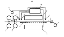
図1は、本発明の鋼材の製造方法(以下「本発明の製造方法」という。)を適用可能な、鋼材の製造装置の形態例を示す概略図であり、鋼材が、紙面左側から右側へと搬送される様子を示している。図2は、本発明の製造方法の形態例を簡略化して示すフローチャートである。
1. FIG. 1 is a schematic diagram showing an embodiment of a steel material manufacturing apparatus to which a steel material manufacturing method of the present invention (hereinafter referred to as “the manufacturing method of the present invention”) can be applied. It shows a state of being conveyed from the left side to the right side. FIG. 2 is a flowchart showing a simplified example of the manufacturing method according to the present invention.
図1に示すように、鋼材の製造装置100は、仕上圧延機2、2、…(以下、単に「仕上圧延機2」ということがある。)と、仕上圧延機2の出側に設置された、板厚測定手段(板厚測定装置)3、及び、第1温度測定手段(温度計)4と、温度計4の下流側に設置された、冷却手段としての冷却装置5と、冷却装置5の下流側に設置された、第2温度測定手段(温度計)6と、温度計6の下流側に設置された巻取手段7と、を備えている。仕上圧延機2によって圧延された鋼板1は、搬送テーブル8上を搬送されて冷却装置5へと達し、冷却装置5から鋼板1の上面側及び下面側へと噴射される水等によって冷却された後、巻取手段7によって巻き取られる。鋼材の製造装置100において、搬送テーブル8上を搬送される鋼板1の搬送速度は、仕上圧延機2に接続された鋼板速度測定手段(鋼板速度測定装置)9によって測定され、鋼板1を冷却する冷却装置5の動作は、鋼材の冷却制御装置10によって制御される。
As shown in FIG. 1, the steel
図2に示すように、本発明の製造方法は、等温変態線図変形工程(工程S1)と、第1温度測定工程(工程S2)と、熱量算出工程(工程S3)と、変態発熱量算出工程(工程S4)と、温度予測工程(工程S5)と、第2温度測定工程(工程S6)と、動作制御工程(工程S7)と、を備えている。 As shown in FIG. 2, the manufacturing method of the present invention includes an isothermal transformation diagram transformation step (step S1), a first temperature measurement step (step S2), a calorific value calculation step (step S3), and a transformation calorific value calculation. A process (process S4), a temperature prediction process (process S5), a second temperature measurement process (process S6), and an operation control process (process S7) are provided.
<等温変態線図変形工程S1>
工程S1は、文献等に掲載されているTTT曲線図によって等温変態挙動が把握される鋼材の組成と、鋼板1の組成とが異なる場合に備えられる工程であり、鋼板1の等温変態挙動を把握できるように、文献等に掲載されているTTT曲線図を変形する工程である。図3に、TTT曲線図を概略的に示す。図3の縦軸は温度[℃]、横軸は時間[s]であり、図3のPsは等温変態が開始される時間と温度との関係を示す曲線、同Pfは等温変態が終了する時間と温度との関係を示す曲線である。工程S1では、図3にΔts、ΔTs、Δtf、及びΔTfで表される4つの変形パラメータを用いて曲線Ps及び曲線Pfをスライドさせることにより、TTT曲線図を変形する。
<Isothermal transformation diagram deformation process S1>
Step S1 is a step provided when the composition of the steel material whose isothermal transformation behavior is grasped by the TTT curve diagram published in the literature and the composition of the
工程S1では、まず、鋼板1の組成と近い組成の鋼材(以下、「鋼材M」ということがある。)に対して作成されているTTT曲線図を、変形対象のTTT曲線図として準備する。鋼板1の組成と近い組成か否かの判断は、等温変態挙動への影響が大きい添加元素(例えば、炭素等)の含有量が近いか否かによって判断することができる。本発明では鋼板1の当該添加元素の含有量をXとするとき、当該添加元素の含有量が0.58X以上1.2X以下である鋼材を、鋼材Mとすることができる。さらに、当該添加元素含有量が0.80X以上1.1X以下である鋼材を鋼材Mとすることが精度の観点からより好ましい。
In step S1, first, a TTT curve diagram created for a steel material having a composition close to that of the steel plate 1 (hereinafter sometimes referred to as “steel material M”) is prepared as a TTT curve diagram to be deformed. The determination as to whether or not the composition is close to the composition of the
次に、上記4つの変形パラメータを導出する。当該4つの変形パラメータは、文献等に掲載されているTTT曲線図を用いて算出される変態発熱量と、後述する工程S3で算出される水冷抜熱量と空冷抜熱量との総和を用いて予測される、冷却装置5通過後の鋼板温度と、温度計6によって測定される鋼板温度との差が最小となるように定められる。
Next, the above four deformation parameters are derived. The four deformation parameters are predicted using the total amount of transformation heat generation calculated using a TTT curve diagram published in literature and the like, and the water-cooled heat extraction amount and air-cooled heat extraction amount calculated in step S3 described later. The difference between the steel plate temperature after passing through the
本発明の製造方法、及び、以下に示す本発明(以下、単に「本発明」という。)において、ある1つの鋼板に対し、上記ΔTs、ΔTf、Δts及びΔtfの4つのパラメータは、これらのパラメータによって変形されたTTT曲線図から算出される変態発熱量と、後述する工程S3で算出される水冷抜熱量と空冷抜熱量との総和を用いて予測される、冷却装置5通過後の鋼板温度と、温度計6によって測定される鋼板温度との差が最小となるように最適化手法(例えば非線形最小二乗法)を用いて導出することができる。
前述のパラメータ導出を板厚や添加元素の含有量が異なる複数の鋼板に対して行うと、鋼板の数と同数のΔTs、ΔTf、Δts及びΔtfを得る。例えば、ΔTsは鋼板の数と同数あるが、鋼板の板厚や添加元素の含有量と相関関係を持ち、この関係を数式として表すことができ、同様に、ΔTf、Δts及びΔtfも数式として表すことができる。
In the manufacturing method of the present invention and the present invention shown below (hereinafter simply referred to as “the present invention”), the four parameters of ΔT s , ΔT f , Δt s and Δt f are as follows for a certain steel sheet. After passing through the
When the above-described parameter derivation is performed on a plurality of steel plates having different thicknesses and additive element contents, ΔT s , ΔT f , Δt s and Δt f equal to the number of steel plates are obtained. For example, ΔT s is the same as the number of steel plates, but has a correlation with the thickness of the steel plate and the content of additive elements, and this relationship can be expressed as a mathematical formula. Similarly, ΔT f , Δt s and Δt f Can also be expressed as a mathematical expression.
本発明において、鋼板の炭素含有量が0.45%未満である場合、上記4つの変形パラメータは、下記式1〜式4のように表すことができる。これに対し、鋼板の炭素含有量が0.45%以上である場合、上記4つの変形パラメータは、下記式5〜式8のように表すことができる。下記式1〜式8において、hsは鋼板の板厚[mm]、Cは鋼板の炭素含有量[%]である。
In the present invention, when the carbon content of the steel sheet is less than 0.45%, the above four deformation parameters can be expressed as the following
![]()
![]()
![]()
![]()
![]()
![]()
![]()
![]()
![]()
![]()
![]()
![]()
![]()
![]()
![]()
![]()
ここで、本発明が適用される炭素含有量が0.45%未満の鋼板を「鋼板A」、本発明が適用される炭素含有量が0.45%以上の鋼板を「鋼板B」とする。鋼板Aに対しては、炭素含有量0.44%のTTT曲線図(公知のもの)を変形して使用し、鋼板Bに対しては、炭素含有量0.77%のTTT曲線図(公知のもの)を変形して使用する。変動対象のTTT曲線図の炭素含有量をXと仮定したとき、変動対象のTTT曲線図によって等温変態挙動が把握される鋼材の炭素含有量は0.5844X以上1.1689X以下であることが好ましい。その理由は、既存の0.77%のTTT曲線図を変形して適用される範囲を炭素含有量が0.45%〜0.9%の鋼板と仮定したためである。一方、炭素含有量が0.45%未満の鋼板に対しては、既存の0.44%のTTT曲線図を変形して使用することが好ましい。本発明を鋼板Aに適用する場合には、上記式1〜式4に鋼板Aの板厚を代入して、Δts、ΔTs、Δtf、及びΔTfの数値を算出し、これらの数値の分だけ、変動対象であるTTT曲線図の曲線Ps及び曲線Pfをスライドさせることで、TTT曲線図を変形することができる。一方、本発明を鋼板Bに適用する場合には、上記式5〜式8に鋼板Bの板厚及び炭素含有量を代入して、ΔTs、Δts、ΔTf、及びΔtfの数値を算出し、これらの数値の分だけ、変動対象であるTTT曲線図の曲線Ps及び曲線Pfをスライドさせることで、TTT曲線図を変形することができる。なお、炭素含有量の少ない鋼板Aは炭素含有量に対する等温変態挙動の変化が小さいため、上記式1〜式4に炭素含有量の項がない。本発明を炭素含有量が0.45%、板厚が3mmの鋼板Bに適用する場合には、上記式5〜式8に、炭素含有量と板厚の値を代入して、Δts、ΔTs、Δtf、及びΔTfの数値を算出し、これらの数値の分だけ、変動対象である炭素含有量0.77%のTTT曲線図の曲線Ps及び曲線Pfをスライドさせることで、TTT曲線図を変形することができる。つまり、鋼板Bの炭素含有量が0.45%、板厚が3mmである場合には、上記式5〜式8より、Δts=0.146、ΔTs=16.8、Δtf=3.49、ΔTf=−26.0となる。そのため、変動対象である炭素含有量0.77%のTTT曲線図の曲線Psを、時間軸の正の方向へ0.146だけ平行移動させ、さらに、温度軸の正の方向へ16.8だけ平行移動させることにより、変形後のTTT曲線図における曲線Psを得ることができる。そして、変動対象である炭素含有量0.77%のTTT曲線図の曲線Pfを、時間軸の正の方向へ3.49だけ平行移動させ、さらに、温度軸の負の方向へ26.0だけ平行移動させることにより、変形後のTTT曲線図における曲線Pfを得ることができる。
このようにして、Δts、ΔTs、Δtf、及びΔTfを用いてTTT曲線図を変形する工程が、工程S1である。
Here, a steel plate having a carbon content of less than 0.45% to which the present invention is applied is referred to as “steel plate A”, and a steel plate having a carbon content of 0.45% or more to which the present invention is applied is referred to as “steel plate B”. . For steel plate A, a TTT curve diagram having a carbon content of 0.44% (known one) is used by modification, and for steel plate B, a TTT curve diagram having a carbon content of 0.77% (known one). )). Assuming that the carbon content of the variation target TTT curve diagram is X, the carbon content of the steel material whose isothermal transformation behavior is grasped by the variation target TTT curve diagram is preferably 0.5844X or more and 1.1689X or less. . The reason is that it is assumed that the existing 0.77% TTT curve diagram is deformed and applied to a steel sheet having a carbon content of 0.45% to 0.9%. On the other hand, for a steel sheet having a carbon content of less than 0.45%, the existing 0.44% TTT curve diagram is preferably used by being modified. When the present invention is applied to the steel sheet A, the values of Δt s , ΔT s , Δt f , and ΔT f are calculated by substituting the thickness of the steel sheet A into the
In this way, the step of deforming the TTT curve diagram using Δt s , ΔT s , Δt f , and ΔT f is step S1.
<第1温度測定工程S2>
工程S2は、温度計4によって、仕上圧延機2によって圧延された鋼板1の温度を測定する工程である。工程S2で測定された温度と、下記工程S3で算出される水冷抜熱量及び空冷抜熱量の和と、下記工程S4で算出される変態発熱量と、を用いて、下記工程S5で鋼板温度が予測される。
<First temperature measurement step S2>
Step S <b> 2 is a step of measuring the temperature of the
<熱量算出工程S3>
工程S3は、冷却装置5から噴射される水を介して鋼板1の表面から放出される水冷抜熱量と、鋼板1が温度計4から温度6へと搬送される間に、鋼板1の表面から空気へと放出される空冷抜熱量との和を算出する工程である。ここで、鋼板1の上面側の水冷抜熱量をqwu[kcal/m2・h]、同下面側の水冷抜熱量をqwd[kcal/m2・h]、空気との対流による鋼板1の空冷抜熱量をqe[kcal/m2・h]、輻射による鋼板1の空冷抜熱量をqr[kcal/m2・h]とするとき、qwu、qwd、qe、及び、qrは、以下の式で表される。
<Health calculation step S3>
Step S3 is performed from the surface of the
![]()
![]()

![]()
![]()
上記式9〜式12において、haは対流の熱伝達率[kcal/m2・h・℃]、Tsは鋼板の表面温度[℃]、Taは雰囲気温度[℃]、σはステファン・ボルツマン定数、εは輻射率、Wuは冷却装置5から鋼板1の上面側へと噴射される水の水量密度[m3/m2・min]、Wdは冷却装置5から鋼板1の下面側へと噴射される水の水量密度[m3/m2・min]、Twは冷却装置5から鋼板1へと噴射される水の温度[℃]、Vは搬送テーブル3上を搬送される鋼板1の搬送速度[m/min]、zuは鋼板1の上面側の冷却能補正係数、zdは鋼板1の下面側の冷却能補正係数、a〜hは定数、である。
In the above formulas 9 to 12, h a is the convective heat transfer coefficient [kcal / m 2 · h · ° C.], T s is the steel sheet surface temperature [° C.], T a is the ambient temperature [° C.], and σ is stefan. Boltzmann constant, ε is the emissivity, W u is the water density of water sprayed from the
上記式9〜式12より、鋼板1の上面側から放出される熱量の総和qu[kcal/m2・h]は、「qu=qwu+qe+qr」で表され、同下面側から放出される熱量の総和qd[kcal/m2・h]は、「qd=qwd+qe+qr」で表される。したがって、工程S3で算出される、鋼板の表面から放出される熱量の総和は、「qu+qd」により求めることができる。
なお、鋼板1の熱伝導率をλ[kcal/m・h・℃]、鋼板1の板厚をh1[m]、板厚方向位置をx[m]、時間をt[s]、鋼板の上面温度をTu[℃]、鋼板の下面温度をTd[℃]、とするとき、上記qu及びqdは、以下の式により表すことができる。
From the above formulas 9 to 12, the total amount q u [kcal / m 2 · h] of heat released from the upper surface side of the
The thermal conductivity of the
<変態発熱量算出工程S4>
工程S4は、TTT曲線図を用いて、鋼板1の変態発熱量を算出する工程である。TTT曲線図を図4に、TTT曲線図から把握可能な等温変態挙動を図5に、それぞれ概略的に示す。図4の縦軸は温度[℃]、横軸は時間[s]である。図4のtsは温度Tにおける等温変態が開始される時間、同tfは温度Tにおける等温変態が終了する時間、をそれぞれ示している。また、図5の縦軸は変態率、横軸は時間[s]であり、図5のts及びtfは、図4のts及びtfと対応している。図4及び図5において、図3と同様の曲線には、図3で使用した記号を付し、その説明を省略する。
<Transformation calorific value calculation step S4>
Step S4 is a step of calculating the transformation heat value of the
図4で表される等温変態挙動は、下記式15で近似され、式15の変態率と時間との関係は、図5で表される。
The isothermal transformation behavior represented in FIG. 4 is approximated by the following
このように、TTT曲線図から、等温変態する鋼材の変態率を導出することができる。ところが、本発明によって鋼板温度を予測される鋼板1は、冷却装置5によって水冷されるほか、空冷されるため、仕上圧延機2の下流側へと搬送されるにつれて、温度が低下していく。温度が連続的に変化する場合には、上記図4及び図5をそのまま適用することができないため、本発明では、温度が連続的に変化する形態を、特定の温度に微小時間だけ保持される段階の積み重ね(等温変態の積み重ね)により温度が段階的に変化する形態で近似することにより、温度が変化する場合の変態率を導出する。図6に、連続的に変化する鋼板温度及び微小時間で区切られた鋼板温度と、時間との関係を示す。図6において、Δt1、Δt2、及びΔt3は微小時間を、T1、T2、及びT3は、Δt1、Δt2、及びΔt3の時の鋼板温度を、それぞれ示している。また、図7に、温度T1、T2、及びT3のそれぞれの温度で鋼板が等温変態した場合の、変態率と時間との関係の概念図を示す。以下、図4〜図7を参照しつつ、説明を続ける。
Thus, the transformation rate of the steel material that undergoes isothermal transformation can be derived from the TTT curve diagram. However, the
図6及び図7に示すように、連続冷却時の変態挙動を、各温度T1、T2、T3、…における微小時間の等温変態の積み重ねであると考えると、冷却中の時間ti、温度Tiにおける変態率ξiは、時間ti−1、温度Ti−1における変態率ξi−1から、下記式16及び式17にて算出することができる。ここで、ξiは変態率、Tiは温度[℃]、Δtiは微小時間[s]である。そして、図7に示すように、このようにして算出された各ξiをつなぎ合わせれば、連続冷却中の変態率ξ(図7右端の曲線)を導出することができる。 As shown in FIGS. 6 and 7, the transformation behavior during continuous cooling, the temperature T 1, T 2, T 3 , considering that the accumulation of small time isothermal transformation in ..., the time t i during cooling , transformation rate xi] i at temperature T i may be time t i-1, the transformation rate xi] i-1 at the temperature T i-1, is calculated by the following equation 16 and equation 17. Here, ξ i is the transformation rate, T i is the temperature [° C.], and Δt i is the minute time [s]. As shown in FIG. 7, the transformation rate ξ during continuous cooling (the curve at the right end of FIG. 7) can be derived by connecting the ξ i calculated in this way.
![]()
![]()
次に、変態率から変態発熱量を算出する方法を説明する。変態発熱量Q[kcal/m3・h]は、下記式18にて算出することができる。 Next, a method for calculating the transformation heat value from the transformation rate will be described. The transformation calorific value Q [kcal / m 3 · h] can be calculated by the following equation 18.
式18において、tは時間[s]、ξは変態率である。また、βは変態潜熱[cal/g]であり、鋼材の組成が特定されると一意に特定される物理量である。この変態潜熱は、市販の計算ソフト(例えば、Thermo−Calc等)に鋼材の組成を入力することにより、求めることができる。
以上より、連続冷却中の変態率ξと変態潜熱βを用いて、変態発熱量Qを算出する工程が、工程S4である。
In Equation 18, t is time [s] and ξ is the transformation rate. Further, β is transformation latent heat [cal / g], which is a physical quantity uniquely specified when the composition of the steel material is specified. This transformation latent heat can be obtained by inputting the composition of the steel material into commercially available calculation software (for example, Thermo-Calc).
As described above, the step of calculating the transformation calorific value Q using the transformation rate ξ and the transformation latent heat β during continuous cooling is step S4.
<温度予測工程S5>
工程S5は、上記工程S2で測定された鋼板温度と、上記工程S3で算出された水冷抜熱量と空冷抜熱量の和「qu+qd」と、上記工程S4で算出された変態発熱量Qと、を用いて、冷却された鋼板の温度を予測する工程である。温度計4によって温度を測定された鋼板1は、その後、工程S3で算出された熱量を表面から放出するため温度が低下する一方、工程S4で算出された変態発熱量の分だけ温度が上昇する。そのため、温度計4によって測定された温度から、熱量の放出及び発生の収支による温度変動分を減じることで、鋼板温度を予測することができる。
<Temperature prediction step S5>
In step S5, the steel sheet temperature measured in step S2 above, the sum “q u + q d ” of the water-cooled heat removal amount and air-cooled heat removal amount calculated in step S3, and the transformation heat generation amount Q calculated in step S4 above. And predicting the temperature of the cooled steel sheet. The temperature of the
<第2温度測定工程S6>
工程S6は、温度計6によって、冷却装置5を通過した後の鋼板1の温度(冷却温度)を測定する工程である。本発明の製造方法では、上記工程S5で予測された鋼板温度と、工程S6で測定された鋼板温度とが一致するように、下記工程S7において、冷却装置5の動作が制御される。
<Second temperature measurement step S6>
Step S <b> 6 is a step of measuring the temperature (cooling temperature) of the
<動作制御工程S7>
工程S7は、上記工程S5で予測された鋼板温度と、上記工程S6で測定された鋼板温度とが一致するように、冷却装置5の動作を制御する工程である。上述のように、上記工程S5では、変態発熱量と、水冷抜熱量と空冷抜熱量との総和を用いて、鋼板温度が予測されるので、冷却装置5を通過後の鋼板温度を高精度に予測することができる。したがって、本発明の製造方法では、上記工程S5で予測された鋼板温度と、上記工程S6で測定された鋼板温度とが一致するように冷却装置5の動作を制御することで、巻取手段7によって巻き取られる鋼板1の温度を高精度に制御することができる。
<Operation control step S7>
Step S7 is a step of controlling the operation of the
工程S7で、冷却装置5の動作を制御する方法は、特に限定されるものではないが、例えば、冷却装置5へと供給される水が流通する配管に設けられた流量調整バルブの開閉を切り替えることにより、制御することができる。
The method for controlling the operation of the
以上、本発明の製造方法に備えられる、工程S1〜工程S7について説明したが、上述のように、工程S4では、微小時間毎の変態率ξを導出し、当該変態率ξの時間微分に変態潜熱βを乗ずることにより、変態発熱量Qが算出される。それゆえ、本発明を実際に適用する際には、温度計4及び温度計6によって挟まれる領域を、変態率ξを導出する際の微小時間と対応するn個の微小空間に分割し(鋼板が当該微小時間で移動する距離毎に分割し)、当該微小空間毎に、上記工程S3及び上記工程S4を行なう。ここで、上記工程S5は、上記工程S3及び上記工程S4の算出結果が用いられるため、本発明の製造方法では、上記工程S5も、微小空間毎に行なわれる。すなわち、本発明の製造方法では、上記工程S5によって各微小空間の出口における鋼板温度を予測し、かかる予測を繰り返すことで、冷却装置5を通過した後の鋼板温度を予測する。
As described above, the steps S1 to S7 included in the manufacturing method of the present invention have been described. However, as described above, in the step S4, the transformation rate ξ for each minute time is derived and transformed into the time derivative of the transformation rate ξ. By multiplying the latent heat β, the transformation calorific value Q is calculated. Therefore, when the present invention is actually applied, the region sandwiched between the thermometer 4 and the
図8に、微小空間毎に行われる上記工程S3〜工程S5を備える、本発明の製造方法のフローチャートを簡略化して示す。図8に示すように、本発明の製造方法では、まず最初に、TTT曲線データを冷却制御装置10に入力し、上記工程S1によって、入力したTTT曲線が変形される。その後、上記微小空間(以下、「iゾーン」等と表記することがある。)の長さと鋼板速度測定装置9によって測定された速度から、鋼板1がiゾーンを通過する時間が算出される。その後、i−1ゾーンの出口における鋼板温度が読み込まれ(i=1のときは、上記工程S2によって測定された温度が読み込まれる)、上記工程S3によって鋼板表面から放出される熱量の総和が算出される。その後、上記工程S4によって変態発熱量が算出され、読み込まれた鋼板温度と、算出された放出熱量の総和及び変態発熱量から、iゾーンの出口における鋼板温度が予測される(上記工程S5)。図8に示すように、工程S3〜工程S5は、i=nまで繰り返され、最終ゾーン(i=nであるゾーン)の出口における温度(冷却装置5を通過した後の鋼板温度)が予測される。そして、このようにして鋼板温度を予測する工程のほかに、さらに、温度計6によって実際の鋼板温度を測定する工程S6が備えられ、工程S5で予測された鋼板温度と工程S6で測定された鋼板温度とが一致するように、工程S7で冷却装置5の動作が制御される。
In FIG. 8, the flowchart of the manufacturing method of this invention provided with the said process S3-process S5 performed for every micro space is simplified and shown. As shown in FIG. 8, in the manufacturing method of the present invention, first, TTT curve data is input to the
なお、本発明の製造方法に関する上記説明では、等温変態線図変形工程S1が備えられる形態を例示したが、本発明の製造方法は当該形態に限定されるものではない。上述のように、等温変態線図変形工程S1は、文献等に掲載されているTTT曲線図によって等温変態挙動が把握される鋼材の組成と、鋼板1の組成とが異なる場合に備えられる工程であるため、文献等に掲載されているTTT曲線図によって等温変態挙動が把握される鋼材の組成と、鋼板1の組成とが一致する場合には、等温変態線図変形工程S1が備えられない形態とすることも可能である。
In addition, in the said description regarding the manufacturing method of this invention, although the form provided with isothermal transformation diagram deformation | transformation process S1 was illustrated, the manufacturing method of this invention is not limited to the said form. As described above, the isothermal transformation diagram deformation step S1 is a step provided when the composition of the steel material whose isothermal transformation behavior is grasped by the TTT curve diagram published in the literature and the composition of the
2.鋼材の冷却制御装置及び鋼材の製造装置
図9は、本発明の鋼材の製造装置の形態例を示す概略図であり、鋼板が、紙面左側から右側へと搬送される様子を示している。図9において、図1と同様の構成を採るものには、図1で使用した符号と同符号を付し、その説明を適宜省略する。以下、図9を参照しつつ、本発明の鋼材の冷却制御装置、及び、本発明の鋼材の製造装置について説明する。
2. Steel Material Cooling Control Device and Steel Material Manufacturing Device FIG. 9 is a schematic view showing an embodiment of the steel material manufacturing device of the present invention, and shows how the steel plate is conveyed from the left side to the right side of the drawing. 9, components having the same configuration as in FIG. 1 are denoted by the same reference numerals as those used in FIG. 1, and description thereof is omitted as appropriate. Hereinafter, the steel material cooling control device of the present invention and the steel material manufacturing device of the present invention will be described with reference to FIG. 9.
図9に示すように、本発明の鋼材の製造装置100は、仕上圧延機2、2、…と、仕上圧延機2の出側に設置された、板厚測定手段(板厚測定装置)3、及び、第1温度測定手段(温度計)4と、温度計4の下流側に設置された、冷却手段としての冷却装置5と、冷却装置5の下流側に設置された、第2温度測定手段(温度計)6と、温度計6の下流側に設置された巻取手段7と、冷却装置5の動作を制御可能な鋼材の冷却制御装置10と、を備えている。鋼材の製造装置100において、搬送テーブル8上を搬送される鋼板1の搬送速度は、仕上圧延機2に接続された鋼板速度測定手段(鋼板速度測定装置)9によって測定される。
As shown in FIG. 9, the steel
本発明の鋼材の製造装置(以下「本発明の製造装置」という。)100に備えられる冷却装置5の動作は、本発明の鋼材の冷却制御装置(以下「冷却制御装置」という。)10によって制御される。冷却制御装置10には、冷却装置5の動作制御を実行するCPU11と、当該CPU11に対する記憶装置とが備えられている。CPU11は、マイクロプロセッサユニット及びその動作に必要な各種周辺回路を組み合わせて構成され、CPU11に対する記憶装置は、例えば、冷却装置5の動作制御に必要なプログラムや各種データを記憶するROM12と、CPU11の作業領域として機能するRAM13等を組み合わせて構成される。当該構成に加えて、さらに、CPU11が、ROM12に記憶されたソフトウエアと組み合わされることにより、本発明の冷却制御装置10が機能する。
The operation of the
鋼板速度測定装置9、板厚測定装置3、温度計4、及び、温度計6からの出力信号は、入力ポート14を介して、入力信号としてCPU11へと到達する。CPU11は、上記入力信号、及び、ROM22に記憶されたプログラムに基いて、出力ポート15を介して、冷却装置5に対する動作指令を制御する。そして、当該動作指令に基いて、例えば、上記流量調整バルブの開閉が制御され、このようにして動作を制御された冷却装置5によって、鋼板1が水冷される。ここで、ROM12に記憶されるデータの具体例としては、TTT曲線図のデータ等を挙げることができる。また、ROM12に記憶されるプログラムの具体例としては、上記工程S1で上記4つの変形パラメータを算出する際に使用される計算プログラム、鋼板速度測定装置9によって測定された速度から、鋼板1がiゾーンを通過する時間を算出する際に使用される計算プログラム、上記工程S3で水冷抜熱量及び空冷抜熱量を算出する際に使用される計算プログラム、上記工程S4で変態発熱量を算出する際に使用される計算プログラム、及び、上記工程S5で鋼板の温度を予測する際に使用される計算プログラム等を挙げることができる。すなわち、図9に示す形態の鋼材の製造装置100に備えられる冷却制御装置10では、CPU11が、等温変態線図変形手段、iゾーン通過時間算出手段、熱量算出手段、変態発熱量算出手段、温度予測手段、及び、制御手段として機能する。
Output signals from the steel plate speed measuring device 9, the plate
このように、本発明の冷却制御装置は、上記本発明の製造方法における工程S1、工程S3、工程S4、及び、工程S5の処理を行うことができ、これらの処理に基いて、冷却装置の動作が制御される。したがって、本発明の冷却制御装置、及び、当該冷却制御装置を備える本発明の製造装置によれば、鋼板の温度を高精度に制御することができる。 Thus, the cooling control device of the present invention can perform the processes of step S1, step S3, step S4, and step S5 in the manufacturing method of the present invention, and based on these processes, Operation is controlled. Therefore, according to the cooling control apparatus of this invention and the manufacturing apparatus of this invention provided with the said cooling control apparatus, the temperature of a steel plate can be controlled with high precision.
本発明の冷却制御装置10に関する上記説明では、等温変態線図変形手段、熱量算出手段、変態発熱量算出手段、温度予測手段、及び、制御手段として機能するCPU11が備えられる形態を例示したが、本発明の冷却制御装置は当該形態に限定されない。CPU11に備えられる上記各機能は、複数の処理装置等に備えられていても良く、冷却制御装置がプロセスコンピュータである場合には、1台又は複数台のプロセスコンピュータからなる冷却制御装置に、上記各機能を組み込まれた形態とすることも可能である。
In the above description regarding the
また、本発明によって温度を高精度に制御される鋼板は、特に限定されるものではない。本発明によって温度を高精度に制御される鋼板としては、JIS G4051:2005「機械構造用炭素鋼鋼材」、JIS G4401:2006「炭素工具鋼鋼材」、JIS G4403:2006「高速度工具鋼鋼材」、JIS G4404:2006「合金工具鋼鋼材」、及び、旧JIS G4410「中空鋼鋼材」等で規定される鋼材を例示することができる。これらの中でも、JIS G4051:2005「機械構造用炭素鋼鋼材」で規定される、S33C、S35C、S38C、S40C、S43C、S45C、S48C、S50C、S53C、S55C、及び、S58C、並びに、JIS G4401:2006「炭素工具鋼鋼材」で規定される、SK90、SK85、SK80、SK75、SK70、SK65、及び、SK60(以下、単に「S35C」、「S50C」、「SK90」、及び、「SK80」等という。)は、鋼板温度をより一層高精度に制御することができるため好ましい。 Moreover, the steel plate whose temperature is controlled with high accuracy by the present invention is not particularly limited. As steel plates whose temperature is controlled with high accuracy according to the present invention, JIS G4051: 2005 “carbon steel for machine structure”, JIS G4401: 2006 “carbon tool steel”, JIS G4403: 2006 “high speed tool steel” , JIS G4404: 2006 “Alloy tool steel”, old JIS G4410 “Hollow steel” and the like. Among these, S33C, S35C, S38C, S40C, S43C, S45C, S48C, S50C, S53C, S55C, and S58C, as defined in JIS G4051: 2005 “Carbon Steel for Mechanical Structure”, and JIS G4401: SK90, SK85, SK80, SK75, SK70, SK65, and SK60 (hereinafter simply referred to as “S35C”, “S50C”, “SK90”, “SK80”, etc.) defined in 2006 “Carbon Tool Steel” .) Is preferable because the steel plate temperature can be controlled with higher accuracy.
以下、図9を参照しつつ、本発明を適用した巻取温度制御試験について説明する。 Hereinafter, the winding temperature control test to which the present invention is applied will be described with reference to FIG.
1.供試材
炭素を0.8%、マンガンを0.5%含有する、板厚2.8mmのSK80相当材を、実施例1にかかる鋼板、及び、比較例1にかかる鋼板とした。また、炭素を0.9%、マンガンを0.5%含有する、板厚2.3mmのSK90相当材を、実施例2にかかる鋼板、及び、比較例2にかかる鋼板とした。さらに、炭素を0.5%、マンガンを0.8%含有する、板厚3.0mmのS50C相当材を、実施例3にかかる鋼板、及び、比較例3にかかる鋼板とした。加えて、炭素を0.3%、マンガンを0.7%含有する、板厚4.0mmのS35C相当材を、実施例4にかかる鋼板、及び、比較例4にかかる鋼板とした。
1. Test Material An SK80 equivalent material with a thickness of 2.8 mm containing 0.8% carbon and 0.5% manganese was used as a steel plate according to Example 1 and a steel plate according to Comparative Example 1. Further, a SK90 equivalent material having a plate thickness of 2.3 mm and containing 0.9% carbon and 0.5% manganese was used as a steel plate according to Example 2 and a steel plate according to Comparative Example 2. Furthermore, a steel plate according to Example 3 and a steel plate according to Comparative Example 3 were made of an S50C equivalent material having a plate thickness of 3.0 mm and containing 0.5% carbon and 0.8% manganese. In addition, an S35C equivalent material having a plate thickness of 4.0 mm and containing 0.3% carbon and 0.7% manganese was used as a steel plate according to Example 4 and a steel plate according to Comparative Example 4.
2.巻取温度制御試験
炭素を0.8%、マンガンを0.5%含有する鋼材のTTT曲線図(以下、「第1のTTT曲線図」という。)、及び、炭素を0.4%、マンガンを0.8%含有する鋼材のTTT曲線図(以下、「第2のTTT曲線図」という。)を入手し、第1のTTT曲線図及び第2のTTT曲線図のデータを冷却制御装置10へ入力した。そして、冷却装置5により、上記実施例1〜4、及び、比較例1〜4にかかる鋼板のそれぞれを冷却し、冷却装置5によって冷却された後の巻取温度を制御する、巻取温度制御試験を行なった。ここで、上記実施例1〜4にかかる鋼板の冷却時には、変態発熱量を考慮する本発明の製造方法を適用し、上記比較例1〜4にかかる鋼板の冷却時には、変態発熱量を考慮しない従来の製造方法を適用した。
2. Winding temperature control test TTT curve diagram of steel material containing 0.8% carbon and 0.5% manganese (hereinafter referred to as "first TTT curve diagram"), 0.4% carbon, manganese TTT curve diagram (hereinafter referred to as “second TTT curve diagram”) of a steel material containing 0.8% of the steel material, and the
実施例1にかかる鋼板の炭素含有量は、冷却制御装置10へデータを入力した第1のTTT曲線図によって等温変態挙動を把握される鋼材の炭素含有量と同一であったため、実施例1にかかる鋼板の冷却時には、上記工程S1を省略した。これに対し、実施例2〜4にかかる鋼板の炭素含有量は、冷却制御装置10へデータを入力した第1のTTT曲線図又は第2のTTT曲線図によって等温変態挙動を把握される鋼材の炭素含有量と異なっていた。そのため、実施例2にかかる鋼板及び実施例3にかかる鋼板の冷却時には、上記工程S1によって第1のTTT曲線図を変形したTTT曲線図を用いて冷却装置5の動作を制御し、巻取温度を制御した。そして、実施例4にかかる鋼板の冷却時には、上記工程S1によって第2のTTT曲線図を変形したTTT曲線図を用いて冷却装置5の動作を制御し、巻取温度を制御した。なお、実施例1〜4にかかる鋼板の巻取温度制御試験では、上記微小時間を50[ms]とした。
Since the carbon content of the steel sheet according to Example 1 was the same as the carbon content of the steel material whose isothermal transformation behavior was grasped by the first TTT curve diagram in which data was input to the cooling
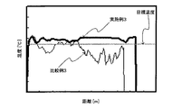
実施例1にかかる鋼板及び比較例1にかかる鋼板の試験結果を図10に、実施例2にかかる鋼板及び比較例2にかかる鋼板の試験結果を図11に、実施例3にかかる鋼板及び比較例3にかかる鋼板の試験結果を図12に、実施例4にかかる鋼板及び比較例4にかかる鋼板の試験結果を図13に、あわせて示す。図10〜図13において、縦軸は温度[℃]、横軸は搬送テーブル3上を搬送される鋼板1の先端からの距離[m]、直線は制御目標温度である。
The test results of the steel plate according to Example 1 and the steel plate according to Comparative Example 1 are shown in FIG. 10, the test results of the steel plate according to Example 2 and the steel plate according to Comparative Example 2 are shown in FIG. The test results of the steel plate according to Example 3 are shown in FIG. 12, and the test results of the steel plate according to Example 4 and the steel plate according to Comparative Example 4 are shown in FIG. 10 to 13, the vertical axis represents the temperature [° C.], the horizontal axis represents the distance [m] from the tip of the
3.結果
図10より、実施例1にかかる鋼板は、鋼板の全長に亘って、ほぼ一定の温度に制御することができたが、比較例1にかかる鋼板は、鋼板の尾端側で温度が降下し、鋼板の先端側及び尾端側において、鋼板温度のばらつきが認められた。比較例1にかかる鋼板において、鋼板の尾端側で温度が降下したのは、搬送テーブル3上を搬送される途中で、比較例1にかかる鋼板の相変態が終了し、変態発熱量が全て放出された後に冷却が実施されたためと考えられる。これに対し、実施例1にかかる鋼板は、変態発熱量を考慮して動作を制御された冷却装置5によって冷却されたため、鋼板の先端から尾端まで温度を高精度に制御することができたと考えられる。したがって、実施例1にかかる鋼板及び比較例1にかかる鋼板の巻取温度制御試験の結果から、冷却装置5で冷却される鋼板の組成と、TTT曲線図における組成とが同一である場合には、上記工程S1を備えない本発明の製造方法によって、鋼板の温度を高精度に制御することができた。
3. Results From FIG. 10, the steel plate according to Example 1 was able to be controlled to a substantially constant temperature over the entire length of the steel plate, but the temperature of the steel plate according to Comparative Example 1 dropped on the tail end side of the steel plate. However, variations in the steel sheet temperature were observed on the front end side and the tail end side of the steel sheet. In the steel plate according to Comparative Example 1, the temperature decreased on the tail end side of the steel plate, while the steel table according to Comparative Example 1 ended in the middle of being conveyed on the conveying table 3, and all of the heat generated by the transformation. This is probably because cooling was performed after the release. On the other hand, the steel plate according to Example 1 was cooled by the
一方、図11及び図12より、実施例2にかかる鋼板、及び、実施例3にかかる鋼板は、鋼板の全長に亘って、高精度に温度を制御することができた。ところが、比較例2にかかる鋼板及び比較例3にかかる鋼板は、鋼板先端側の温度が鋼板尾端側の温度よりも高かった。比較例2にかかる鋼板及び比較例3にかかる鋼板の先端側で温度が高かったのは、相変態が進行し、変態発熱量の放出が大きすぎたためであると考えられる。実施例2にかかる鋼板は比較例2にかかる鋼板と同じ組成であり、実施例3にかかる鋼板は比較例3にかかる鋼板と同じ組成であったが、実施例2にかかる鋼板及び実施例3にかかる鋼板は、変態発熱量を考慮する本発明の製造方法によって温度が制御されていたため、鋼板の全長に亘って、高精度に温度を制御することができた。また、実施例2にかかる鋼板、及び、実施例3にかかる鋼板は、上記工程S1で第1のTTT曲線図を変形したTTT曲線図を用いて、巻取温度が制御されたが、図11及び図12より、変形したTTT曲線図を用いることで、鋼板温度を高精度に制御することができた。したがって、図11及び図12より、本発明によれば、製造対象の鋼材と同一組成について作成されたTTT曲線図を用意できない場合であっても、製造対象の鋼材と近い組成の鋼材について作成されたTTT曲線図を変形して用いることで、鋼板温度を高精度に制御可能であることが確認された。なお、実施例2にかかる鋼板の炭素含有量を1とするとき、第1のTTT曲線図によって等温変態挙動を把握される鋼材の炭素含有量は約0.89であった。また、実施例3にかかる鋼板の炭素含有量を1とするとき、第1のTTT曲線図によって等温変態挙動を把握される鋼材の炭素含有量は1.6であった。 On the other hand, from FIG.11 and FIG.12, the steel plate concerning Example 2 and the steel plate concerning Example 3 were able to control temperature with high precision over the full length of a steel plate. However, in the steel plate according to Comparative Example 2 and the steel plate according to Comparative Example 3, the temperature at the front end side of the steel plate was higher than the temperature at the tail end side of the steel plate. The reason why the temperature was high at the front end side of the steel plate according to Comparative Example 2 and the steel plate according to Comparative Example 3 is considered to be that the phase transformation progressed and the release of the transformation heat generation amount was too large. The steel plate according to Example 2 had the same composition as the steel plate according to Comparative Example 2, and the steel plate according to Example 3 had the same composition as the steel plate according to Comparative Example 3, but the steel plate according to Example 2 and Example 3 were used. Since the temperature of the steel sheet according to the present invention was controlled by the manufacturing method of the present invention in consideration of the transformation calorific value, the temperature could be controlled with high accuracy over the entire length of the steel sheet. Moreover, although the steel plate concerning Example 2 and the steel plate concerning Example 3 were controlled in coiling temperature using the TTT curve figure which deform | transformed the 1st TTT curve figure by said process S1, FIG. And from FIG. 12, the steel plate temperature was able to be controlled with high precision by using the modified TTT curve diagram. Therefore, from FIGS. 11 and 12, according to the present invention, even if a TTT curve diagram created for the same composition as the steel material to be manufactured cannot be prepared, the steel material having a composition close to that of the steel material to be manufactured is prepared. It was confirmed that the steel plate temperature can be controlled with high accuracy by using the modified TTT curve diagram. In addition, when the carbon content of the steel sheet according to Example 2 is 1, the carbon content of the steel material whose isothermal transformation behavior is grasped by the first TTT curve diagram is about 0.89. Moreover, when the carbon content of the steel plate according to Example 3 is 1, the carbon content of the steel material whose isothermal transformation behavior is grasped by the first TTT curve diagram is 1.6.
他方、図13より、実施例4にかかる鋼板は、鋼板の全長に亘って、高精度に温度を制御することができたが、比較例4にかかる鋼板は、鋼板の全長に亘って、目標温度からかけ離れた低温に制御された。これは、比較例4にかかる鋼板では、相変態が進行せず、十分に変態発熱量が放出されていないために起こった現象であると考えられる。実施例4にかかる鋼板は、比較例4にかかる鋼板と同じ組成であったが、実施例4にかかる鋼板は、変態発熱量を考慮する本発明の製造方法によって温度が制御されていたため、鋼板の全長に亘って、高精度に温度を制御することができた。また、実施例4にかかる鋼板は、上記工程S1で第2のTTT曲線図を変形したTTT曲線図を用いて、巻取温度が制御されたが、図13より、変形したTTT曲線図を用いることで、鋼板温度を高精度に制御することができた。したがって、図13より、本発明によれば、製造対象の鋼材と同一組成について作成されたTTT曲線図を用意できない場合であっても、製造対象の鋼材と近い組成の鋼材について作成されたTTT曲線図を変形して用いることで、鋼板温度を高精度に制御可能であることが確認された。なお、実施例4にかかる鋼板の炭素含有量を1とするとき、第2のTTT曲線図によって等温変態挙動を把握される鋼材の炭素含有量は約1.3であった。 On the other hand, from FIG. 13, the steel plate according to Example 4 was able to control the temperature with high accuracy over the entire length of the steel plate, but the steel plate according to Comparative Example 4 was the target over the entire length of the steel plate. Controlled to a low temperature far from the temperature. This is considered to be a phenomenon that occurred because the steel plate according to Comparative Example 4 did not proceed with phase transformation and did not release the amount of heat generated by transformation sufficiently. The steel plate according to Example 4 had the same composition as the steel plate according to Comparative Example 4, but the temperature of the steel plate according to Example 4 was controlled by the manufacturing method of the present invention in consideration of the transformation calorific value. The temperature could be controlled with high accuracy over the entire length. Further, the steel sheet according to Example 4 was controlled in the coiling temperature using the TTT curve diagram obtained by modifying the second TTT curve diagram in the above-described step S1, but the modified TTT curve diagram is used from FIG. Thus, the steel plate temperature could be controlled with high accuracy. Therefore, from FIG. 13, according to the present invention, even when a TTT curve diagram created for the same composition as the steel material to be manufactured cannot be prepared, a TTT curve created for a steel material having a composition close to that of the steel material to be manufactured. It was confirmed that the steel sheet temperature can be controlled with high accuracy by modifying the figure. In addition, when the carbon content of the steel plate according to Example 4 is 1, the carbon content of the steel material whose isothermal transformation behavior is grasped by the second TTT curve diagram is about 1.3.
1 鋼板
2 仕上圧延機
3 板厚測定装置(板厚測定手段)
4 温度計(第1温度測定手段)
5 冷却装置(冷却手段)
6 温度計(第2温度測定手段)
7 巻取手段
8 搬送テーブル
9 鋼板速度測定装置(鋼板速度測定手段)
10 鋼材の冷却制御装置
11 CPU(等温変態線図変形手段、熱量算出手段、変態発熱量算出手段、温度予測手段、制御手段)
12 ROM
13 RAM
14 入力ポート
15 出力ポート
100 鋼材の製造装置
DESCRIPTION OF
4 Thermometer (first temperature measuring means)
5 Cooling device (cooling means)
6 Thermometer (second temperature measuring means)
7 Winding means 8 Transport table 9 Steel plate speed measuring device (steel plate speed measuring means)
DESCRIPTION OF
12 ROM
13 RAM
14
Claims (5)
前記冷却手段によって冷却される前の前記鋼板の温度を測定する、第1温度測定工程と、
前記鋼板の表面から放出される熱量の総和を算出する、熱量算出工程と、
等温変態線図を用いて前記鋼板の変態発熱量を算出する、変態発熱量算出工程と、
前記第1温度測定工程によって測定された前記温度と、前記熱量算出工程によって算出された前記熱量と、前記変態発熱量算出工程によって算出された前記変態発熱量と、を用いて、前記冷却手段で冷却された前記鋼板の温度を予測する、温度予測工程と、
前記冷却手段によって冷却された鋼板の冷却温度を測定する、第2温度測定工程と、
前記温度予測工程によって予測された前記温度と、前記第2温度測定工程によって測定された前記冷却温度とが一致するように、前記冷却手段の動作を制御する、動作制御工程と、
を備え、
さらに、前記鋼板の組成と、前記等温変態線図によって等温変態挙動が把握される鋼材の組成とが異なる場合に、前記鋼板の板厚、又は、前記鋼板の板厚及び前記鋼板に含有される元素の濃度、をパラメータとして有する関数を用いて、前記等温変態線図を変形する、等温変態線図変形工程を有し、
前記等温変態線図変形工程によって変形された等温変態線図を用いて、前記変態発熱量算出工程において前記鋼板の変態発熱量が算出されることを特徴とする、鋼材の製造方法。 A steel sheet manufactured by a finish rolling mill, manufactured through a process of cooling by a cooling means, a steel material manufacturing method,
Measuring the temperature of the steel sheet before being cooled by the cooling means, a first temperature measuring step;
Calculating the total amount of heat released from the surface of the steel sheet;
A transformation calorific value calculation step of calculating a transformation calorific value of the steel sheet using an isothermal transformation diagram;
Using the temperature measured by the first temperature measurement step, the calorie calculated by the calorific value calculation step, and the transformation calorific value calculated by the transformation calorific value calculation step, the cooling means Predicting the temperature of the cooled steel sheet, a temperature prediction step;
A second temperature measuring step of measuring a cooling temperature of the steel sheet cooled by the cooling means;
An operation control step of controlling the operation of the cooling means so that the temperature predicted by the temperature prediction step matches the cooling temperature measured by the second temperature measurement step;
Equipped with a,
Furthermore, when the composition of the steel plate and the composition of the steel material whose isothermal transformation behavior is grasped by the isothermal transformation diagram are different, the steel plate thickness, or the steel plate thickness and the steel plate contain An isothermal transformation diagram transformation step for transforming the isothermal transformation diagram using a function having the element concentration as a parameter;
A method for producing a steel material , wherein the transformation heat generation amount of the steel sheet is calculated in the transformation heat generation amount calculation step using the isothermal transformation diagram deformed by the isothermal transformation diagram deformation step .
前記冷却手段によって冷却される前の前記鋼板の温度を測定する、第1温度測定手段と、First temperature measuring means for measuring the temperature of the steel sheet before being cooled by the cooling means;
前記鋼板の表面から放出される熱量の総和を算出する、熱量算出手段と、A calorific value calculating means for calculating a total amount of heat released from the surface of the steel sheet;
等温変態線図を用いて前記鋼板の変態発熱量を算出する、変態発熱量算出手段と、A transformation calorific value calculation means for calculating a transformation calorific value of the steel sheet using an isothermal transformation diagram;
前記第1温度測定手段によって測定された前記温度と、前記熱量算出手段によって算出された前記熱量と、前記変態発熱量算出手段によって算出された前記変態発熱量とを用いて、前記冷却手段で冷却された前記鋼板の温度を予測する、温度予測手段と、Cooling by the cooling means using the temperature measured by the first temperature measuring means, the calorific value calculated by the calorific value calculating means, and the transformation calorific value calculated by the transformation calorific value calculating means. A temperature predicting means for predicting the temperature of the steel sheet,
前記冷却手段によって冷却された鋼板の冷却温度を測定する、第2温度測定手段と、A second temperature measuring means for measuring a cooling temperature of the steel sheet cooled by the cooling means;
前記温度予測手段によって予測された前記温度と、前記第2温度測定手段によって測定された前記冷却温度とが一致するように、前記冷却手段の動作を制御する、制御手段と、Control means for controlling the operation of the cooling means so that the temperature predicted by the temperature prediction means matches the cooling temperature measured by the second temperature measuring means;
前記鋼板の組成と、前記等温変態線図によって等温変態挙動が把握される鋼材の組成とが異なる場合に、前記鋼板の板厚、又は、前記鋼板の板厚及び前記鋼板に含有される元素の濃度、をパラメータとして有する関数を用いて、前記等温変態線図を変形する、等温変態線図変形手段と、を備え、When the composition of the steel plate and the composition of the steel material whose isothermal transformation behavior is grasped by the isothermal transformation diagram are different, the plate thickness of the steel plate, or the plate thickness of the steel plate and the elements contained in the steel plate An isothermal transformation diagram deforming means for transforming the isothermal transformation diagram using a function having a concentration as a parameter,
前記等温変態線図変形手段によって変形された等温変態線図を用いて、前記変態発熱量算出手段によって前記鋼板の変態発熱量が算出されることを特徴とする、鋼材の冷却制御装置。The steel material cooling control apparatus, wherein the transformation heat generation amount of the steel sheet is calculated by the transformation heat generation amount calculation means using the isothermal transformation diagram deformed by the isothermal transformation diagram deformation means.
前記仕上圧延機によって加工された鋼板を冷却可能な、冷却手段と、A cooling means capable of cooling the steel sheet processed by the finish rolling mill;
請求項3又は4に記載の鋼板の冷却制御装置と、A steel sheet cooling control device according to claim 3 or 4,
を備えることを特徴とする、鋼材の製造装置。An apparatus for manufacturing a steel material, comprising:
Priority Applications (1)
| Application Number | Priority Date | Filing Date | Title |
|---|---|---|---|
| JP2006356780A JP4962005B2 (en) | 2006-12-29 | 2006-12-29 | Steel manufacturing method, steel cooling control device, and steel manufacturing device |
Applications Claiming Priority (1)
| Application Number | Priority Date | Filing Date | Title |
|---|---|---|---|
| JP2006356780A JP4962005B2 (en) | 2006-12-29 | 2006-12-29 | Steel manufacturing method, steel cooling control device, and steel manufacturing device |
Publications (2)
| Publication Number | Publication Date |
|---|---|
| JP2008161924A JP2008161924A (en) | 2008-07-17 |
| JP4962005B2 true JP4962005B2 (en) | 2012-06-27 |
Family
ID=39692084
Family Applications (1)
| Application Number | Title | Priority Date | Filing Date |
|---|---|---|---|
| JP2006356780A Active JP4962005B2 (en) | 2006-12-29 | 2006-12-29 | Steel manufacturing method, steel cooling control device, and steel manufacturing device |
Country Status (1)
| Country | Link |
|---|---|
| JP (1) | JP4962005B2 (en) |
Families Citing this family (4)
| Publication number | Priority date | Publication date | Assignee | Title |
|---|---|---|---|---|
| JP5693392B2 (en) * | 2011-06-15 | 2015-04-01 | 株式会社神戸製鋼所 | Method for calculating transformation rate in steel plate to be cooled or heated, and method for controlling transformation rate of steel plate |
| MA47360B1 (en) * | 2016-12-20 | 2023-06-28 | Arcelormittal | METHOD FOR MANUFACTURING A HEAT-TREATED STEEL SHEET |
| MX2019007172A (en) * | 2016-12-20 | 2019-09-05 | Arcelormittal | A method for manufacturing a thermally treated steel sheet. |
| KR102226653B1 (en) * | 2019-05-28 | 2021-03-11 | 경상국립대학교산학협력단 | Isothermal Transformation Diagram Adjustment Method of Metal |
Family Cites Families (2)
| Publication number | Priority date | Publication date | Assignee | Title |
|---|---|---|---|---|
| JP4529517B2 (en) * | 2003-06-27 | 2010-08-25 | Jfeスチール株式会社 | High carbon steel plate manufacturing method and manufacturing equipment |
| JP4402502B2 (en) * | 2004-04-13 | 2010-01-20 | 東芝三菱電機産業システム株式会社 | Winding temperature controller |
-
2006
- 2006-12-29 JP JP2006356780A patent/JP4962005B2/en active Active
Also Published As
| Publication number | Publication date |
|---|---|
| JP2008161924A (en) | 2008-07-17 |
Similar Documents
| Publication | Publication Date | Title |
|---|---|---|
| RU2404000C2 (en) | Method of cooling control, cooling control device and cooling water amount calculator | |
| JP5835483B2 (en) | Temperature control device | |
| JP5565200B2 (en) | Finishing temperature control device in hot rolling | |
| JP4962005B2 (en) | Steel manufacturing method, steel cooling control device, and steel manufacturing device | |
| JP5564704B2 (en) | Hot finish rolling mill outlet side temperature control device and control method | |
| JP7135962B2 (en) | Steel plate finishing delivery side temperature control method, steel plate finishing delivery side temperature control device, and steel plate manufacturing method | |
| JP2014000593A (en) | Temperature unevenness prediction method of hot rolled steel sheet, flatness control method, temperature unevenness control method and manufacturing method | |
| TWI754979B (en) | Method of controlling a cooling device in a rolling train | |
| JP2005297015A (en) | Winding temperature controller | |
| EA039568B1 (en) | Method for producing a rolled steel product | |
| JP2003039109A (en) | Device for controlling coil winding temperature | |
| JP6021450B2 (en) | Heating furnace operation support system | |
| JP5493993B2 (en) | Thick steel plate cooling control device, cooling control method, and manufacturing method | |
| JP5381740B2 (en) | Thickness control method of hot rolling mill | |
| JP2012011448A (en) | Cooling control method of rolled material, and continuous rolling mill to which the cooling control method is applied | |
| JP5369468B2 (en) | Method for producing hot-rolled metal strip using temperature prediction method of material to be rolled in hot rough rolling | |
| US20220236725A1 (en) | Physical model identification system | |
| JP4736832B2 (en) | Hot finish rolling device and hot finish rolling temperature control method | |
| JP2014079778A (en) | Manufacturing method and manufacturing apparatus of hot rolled steel sheet | |
| JP2023030272A (en) | Temperature prediction device of steel material, cooling control device, method and program | |
| JP6874730B2 (en) | Hot rolling line controller | |
| RU2783688C1 (en) | Method for controlling the cooling device in the rolling mill line | |
| JP7338599B2 (en) | Method for predicting generation of blister scale, method for controlling rolling mill, and method for generating prediction model for generation of blister scale | |
| JP7424335B2 (en) | Heating control method and device, hot-rolled steel plate manufacturing method, and transportation prediction model generation method | |
| JP2017177172A (en) | Cooling control method and cooling apparatus |
Legal Events
| Date | Code | Title | Description |
|---|---|---|---|
| A621 | Written request for application examination |
Free format text: JAPANESE INTERMEDIATE CODE: A621 Effective date: 20090121 |
|
| RD01 | Notification of change of attorney |
Free format text: JAPANESE INTERMEDIATE CODE: A7421 Effective date: 20101101 |
|
| A977 | Report on retrieval |
Free format text: JAPANESE INTERMEDIATE CODE: A971007 Effective date: 20110328 |
|
| A131 | Notification of reasons for refusal |
Free format text: JAPANESE INTERMEDIATE CODE: A131 Effective date: 20110823 |
|
| A521 | Written amendment |
Free format text: JAPANESE INTERMEDIATE CODE: A523 Effective date: 20111012 |
|
| TRDD | Decision of grant or rejection written | ||
| A01 | Written decision to grant a patent or to grant a registration (utility model) |
Free format text: JAPANESE INTERMEDIATE CODE: A01 Effective date: 20120228 |
|
| A01 | Written decision to grant a patent or to grant a registration (utility model) |
Free format text: JAPANESE INTERMEDIATE CODE: A01 |
|
| A61 | First payment of annual fees (during grant procedure) |
Free format text: JAPANESE INTERMEDIATE CODE: A61 Effective date: 20120312 |
|
| R150 | Certificate of patent or registration of utility model |
Ref document number: 4962005 Country of ref document: JP Free format text: JAPANESE INTERMEDIATE CODE: R150 Free format text: JAPANESE INTERMEDIATE CODE: R150 |
|
| FPAY | Renewal fee payment (event date is renewal date of database) |
Free format text: PAYMENT UNTIL: 20150406 Year of fee payment: 3 |
|
| FPAY | Renewal fee payment (event date is renewal date of database) |
Free format text: PAYMENT UNTIL: 20150406 Year of fee payment: 3 |
|
| S111 | Request for change of ownership or part of ownership |
Free format text: JAPANESE INTERMEDIATE CODE: R313111 |
|
| FPAY | Renewal fee payment (event date is renewal date of database) |
Free format text: PAYMENT UNTIL: 20150406 Year of fee payment: 3 |
|
| R350 | Written notification of registration of transfer |
Free format text: JAPANESE INTERMEDIATE CODE: R350 |
|
| S533 | Written request for registration of change of name |
Free format text: JAPANESE INTERMEDIATE CODE: R313533 |
|
| R350 | Written notification of registration of transfer |
Free format text: JAPANESE INTERMEDIATE CODE: R350 |