JP4961631B2 - Game machine - Google Patents
Game machine Download PDFInfo
- Publication number
- JP4961631B2 JP4961631B2 JP2000374181A JP2000374181A JP4961631B2 JP 4961631 B2 JP4961631 B2 JP 4961631B2 JP 2000374181 A JP2000374181 A JP 2000374181A JP 2000374181 A JP2000374181 A JP 2000374181A JP 4961631 B2 JP4961631 B2 JP 4961631B2
- Authority
- JP
- Japan
- Prior art keywords
- display
- liquid crystal
- usage time
- unit
- time
- Prior art date
- Legal status (The legal status is an assumption and is not a legal conclusion. Google has not performed a legal analysis and makes no representation as to the accuracy of the status listed.)
- Expired - Lifetime
Links
Images


Description
【0001】
【発明の属する技術分野】
本発明は、パチンコ機やスロットマシンなどの遊技機に関するものである。
【0002】
【従来の技術】
近年、パチンコ等の遊技機においては、遊技の興趣を向上させるために液晶表示装置などの表示手段を用いたものが主流となっている。
【0004】
【発明が解決しようとする課題】
ここで、表示手段を交換する場合等において、表示手段の実際の使用時間を定量的に把握する手段がないと、適正な交換時期が分からないという問題点があった。
【0005】
本発明は、上記例示した問題点等を解決するためになされたものであり、表示手段の交換時期を適正に把握できる遊技機を提供することを目的としている。
【0006】
【課題を解決するための手段】
この目的を達成するために、請求項1記載の遊技機は、遊技に伴う識別情報の動的表示を行う表示手段を備え、電源断時において前記表示手段の使用時間に応じた値を保持可能な使用時間記憶手段と、電源入時において一定の時間が経過する毎に前記使用時間記憶手段に記憶される値を更新する更新手段と、その更新手段によって更新された前記使用時間記憶手段に記憶される値に基づいて、前記表示手段の使用時間に関する情報を報知する使用時間報知手段と、電源が投入された場合に、前記更新手段による更新が行われてから前記表示手段が前記一定の時間またはそれよりも短い時間であって0より長い特定の時間使用されたものとして、前記使用時間記憶手段に記憶される値を補正する使用時間補正手段とを備えている。
【0008】
【発明の実施の形態】
以下、本発明の好ましい実施例について、添付図面を参照して説明する。図1は、本発明の第1実施例におけるパチンコ機1およびカード読取ユニット24の正面図である。このパチンコ機1は、いわゆる第1種パチンコ機であり、その前面(図1の紙面に対して手前側)には前面枠2が配設されている。前面枠2は、略矩形額縁上に形成されており、前面枠2の略中央部には略矩形状の開口2aが穿設され、かかる開口2aの内周には金枠3が周設されている。この金枠3の内側の上方には、ガラス板4aを装着可能なガラス扉枠4が開閉可能に配設されており、ガラス扉枠4の後方(図1の紙面に対して奥側)には遊技盤5が配設されている。
【0009】
遊技盤5の前面には略円弧状の外レール6が植立され、その外レール6の内側位置には円弧状の内レール7が植立されている。この内レール7および外レール6により囲まれた遊技盤5の前面には、遊技球(打球)が打ち込まれる遊技領域8が形成されており、遊技領域8の周囲には、遊技球が入賞することにより6個の遊技球が賞球として払い出される複数の普通入賞口9が配設されている。この複数の普通入賞口9が配設された遊技領域8の略中央部には、複数種類の識別情報としての図柄などを表示する液晶表示装置10を備えた可変表示装置11が配設されている。
【0010】
この可変表示装置11の液晶表示装置10の手前側周囲には、可変表示装置11の装飾部材を兼ねたセンターフレーム11aが周設されており、このセンターフレーム11aにより液晶表示装置10の周囲が装飾されている。センターフレーム11aの上部中央には表示装置の一種であり7セグメントのLEDで構成される普通図柄表示LED11bが配設されている。
【0011】
可変表示装置11の下方には、図柄作動口(第1種始動口)12が配設されている。この図柄作動口12を遊技球が通過することにより、第1種始動口スイッチ(図示せず)がオンして、可変表示装置11の変動表示が開始されると共に、6個の遊技球が賞球として払い出される。また、図柄作動口12の下方には可変入賞装置13が配設されている。この可変入賞装置13は、遊技盤5に取着可能に形成された本体フレーム13aを備えており、その略中央部には2以上の遊技球が同時に通過可能な幅広矩形状の大入賞口の開口13bが穿設されている。
【0012】
この大入賞口の開口13bは、大入賞口の一部を構成しており、可変表示装置11の変動後の表示結果が、予め定められた図柄の組み合わせ(大当たり表示)の1つと一致する場合に、遊技球が入賞しやすいように所定時間(例えば、30秒間)経過するまで、又は、所定個数(例えば、10個)の遊技球が大入賞口の開口13b内へ入賞するまで、開放されるものである。この大入賞口の開口13bの開閉動作が行われ得る状態が、いわゆる所定の遊技価値の付与された状態(特別遊技状態)である。
【0013】
大入賞口の開口13bには、開閉シャッタ13cが配設されている。この開閉シャッタ13cは、大入賞口の開口13bの形状に合わせて形成されており、大入賞口の開口13bを開閉するものである。また、本体フレーム13aの前面であって、開閉シャッタ13cの前方にはガード部材13dが配設されている。大入賞口は、これら本体フレーム13a、開口13b、開閉シャッタ13c、ガード部材13dで構成されている。
【0014】
可変入賞装置13の下方であって、上述した遊技領域8の最下方には、いずれの入賞口にも入賞しなかった遊技球を遊技領域8外へ排出するためのアウトロ14が形成されている。このアウトロ14の形成された遊技領域8の前方に配設されるガラス扉枠4の下方には、金枠3に開閉可能に取着された前面扉板(腰板)15が配設されている。この前面扉板15の前面には遊技球を貯留し、かつ、遊技球発射装置(図示せず)へ遊技球を供給する上皿16が配設され、その上皿16の下方であって、前面枠2の下側部分には上皿16に貯留しきれなかった遊技球を貯留するための下皿17が配設されている。これら上皿16と下皿17との間であって、前面扉板15の左方部には、遊技に伴う効果音などを発生するためのスピーカ18が配設され、また、下皿17の右側部分には、遊技球を遊技領域8へ打ち込むために遊技者により操作される操作ハンドル19が配設されている。この操作ハンドル19の内部には、遊技球発射装置の発射モータ(図示せず)を回転させるためのスイッチであるハンドルスイッチ19aが内蔵されている。
【0015】
上述した上皿16は、板状に形成された装飾板16aを備えており、その装飾板16aによって前面扉板15の前面が覆われている。装飾板16aの中央には、後述するカード読取ユニット24により読み取られたカードの残高金額を表示するために、7セグメントLEDにより構成された3桁の残高表示器20が配設されている。この残高表示器20の右側には、後述するカード読取ユニット24のカード挿入口25に挿入されたカードを取り出す場合に押下される返却ボタン21が配設される一方、残高表示器20の左側には、貸球の払い出し(貸出)を開始する際に押下される貸出ボタン22が配設されている。また、貸出ボタン22の左側上方には貸出ボタン22が押下可能か否かを報知する貸出ボタンランプ23が配設されている。この貸出ボタンランプ23は、貸出ボタン22が押下可能な状態である場合に点灯される一方、貸出ボタン22が押下不可能な状態である場合に消灯される。よって、遊技者は、この貸出ボタンランプ23を視認することにより、貸出ボタン22が押下可能であるか否かを判断することができる。
【0016】
上記のように構成されたパチンコ機1の左側には、正面視長方形状のカード読取ユニット24が併設されている。カード読取ユニット24はカードに記録された残高金額のデータを読み取るためのものであり、その上下方向における略中央部分には、金銭と同等の有価価値を有するカード挿入口25が縦長に配設されている。このカード挿入口25の上方であって、カード読取ユニット24の上部にはLEDで構成されたカード利用可能ランプ26が配設されている。このカード利用可能ランプ26は、例えば、カード挿入口25へカードが挿入可能である場合に点灯される一方、カード挿入口25へカードが挿入不可能である場合に消灯される。よって、遊技者は、このカード利用可能ランプ26を視認することにより、カード読取ユニット24が使用可能であるか否かを判断することができる。
【0017】
カード挿入口25とカード利用可能ランプ26との間部分であって、カード読取ユニット24の上側位置には、カードに記録された残高金額のデータに基づいて貸出金額を設定するための金額設定ボタン27が配設されており、この金額設定ボタン27を押下することにより貸出金額を100円、200円、300円または500円に設定することができる。金額設定ボタン27の下側には、端数表示ボタン28が配設されている。この端数表示ボタン28は、カードに記録された残高金額が貸出金額の最低額に満たない場合に、その端数を残高表示器20に表示する際に押下される。例えば、貸出金額の最低額が300円に設定されており、200円の残高金額がある場合、端数表示ボタン28が押下されると、残高表示器20には200円の残高が表示されるのである。
【0018】
また、端数表示ボタン28の下側には、略三角形状に形成された上下一対の連結台方向表示ランプ29が配設されている。この一対の連結台方向表示ランプ29は、カード読取ユニット24が接続されているパチンコ機1の配設(並設)方向を示すためのものであり、その内部にそれぞれ1つずつLEDが内蔵されている。よって、例えば、カード読取ユニット24が右側に並設されるパチンコ機1に接続される場合には下側のLEDが点灯され、カード読取ユニット24が左側に並設されるパチンコ機(図示せず)に接続される場合には上側のLEDが点灯される。この連結台方向表示ランプ29の下側には、LEDで構成されたカード挿入中ランプ30が配設されており、このカード挿入中ランプ30はカードがカード挿入口25に挿入されている場合に点灯される一方、カードがカード挿入口25に挿入されていない場合に消灯される。
【0019】
図2は、パチンコ機1に搭載される液晶表示装置10を各ユニット毎に分解して示した斜視図である。尚、図2では、液晶表示装置10の主な構成ユニットだけを図示し、その他のものについては簡単のため、その図示を省略している。
【0020】
液晶表示装置10は、パチンコ機1(図示せず)に着脱自在に止着されており、図2に示すように、主に、液晶パネル53、バックライト54、液晶制御基板L等の各ユニットから構成されている。液晶パネル53は、液晶セルの透光性を調整することによって画像を表示するためのユニットであり、液晶素子と駆動電極とを重合状に形成した液晶セル及び偏光板からなる表示板等で構成されている。液晶パネル53の表示板(図2の左上方奥側)は、可変表示装置11のセンターフレーム11a(図1参照)の開口部からパチンコ機1の前面側に露出され、遊技者に視認可能に配置される。また、液晶パネル53は、コネクタ55を介して後述する液晶制御基板Lと着脱可能に電気的に接続されている。
【0021】
バックライト54は、液晶パネル53に光線を照射するためのユニットであり、液晶セルを透過可能な光線を照射する蛍光管及びその光線を反射させ液晶セルに集中させる反射板等から構成されている。また、バックライト54は、コネクタ56を介して後述する液晶表示基板Lと着脱可能に電気的に接続されている。
【0022】
液晶制御基板Lは、液晶パネル53の液晶セルの駆動電極に電圧を印加して液晶セルの透光性を制御するためのものであり、表示用制御基板Dの画像コントローラ47(図3参照)から送信される命令に基づいて、所定の画像を表示するために所定の液晶セルに電圧を印加する。液晶制御基板Lは、コネクタ55を介して後述する表示用制御基板Dと着脱可能に電気的に接続されている。これら液晶パネル53、バックライト54、液晶制御基板L及び表示用制御基板Dは、樹脂等により箱状に成形されたケース57内に格納されることにより、一体に構成された液晶表示装置10となる。このケース57は、ねじ58によって分解可能に構成された上ケース57aと下ケース57bとを備えており、上ケース57aと下ケース57bとを分解することによって、格納された表示用制御基板Dに設けられた後述するスイッチ50の操作をすることができる。
【0023】
表示用制御基板Dは液晶表示装置10による図柄の変動表示を制御するためのものであり、その一方の面には、表示LED49とスイッチ50とを備えている。表示LED49は、第1〜第3LED49a〜49cの3つのLEDを備えており、発光させる個数を変更することによって、スイッチ50によって指定されたユニットの総使用時間を表示するためのものである。スイッチ50は、押しボタンにより構成される複数のスイッチ50a〜50dを備えている。各スイッチ50a〜50dのいずれかが押下された場合には、押下されたスイッチ50a〜50dに対応するユニットの使用時間に基づいて、表示LED49の発光数が変更される。
【0024】
液晶表示装置10は、上記のように、各ユニットからなる一つのユニットとして構成されており、また、その各ユニットが単独で着脱可能に構成されているので、回収されたパチンコ機1から取り外された液晶表示装置10を他のパチンコ機へそのまま転用(再利用)することができるだけでなく、液晶表示装置10の各ユニット毎に単独で転用することもできる。かかる場合には、表示LED49に表示される総使用時間から各ユニット毎に残寿命を判定し、残寿命に余裕があると判定されたユニットだけを他のパチンコ機に転用することができるので、転用されたユニットが遊技中に故障する等を未然に回避することができるのである。ここで、この実施例では、表示用制御基板Dが液晶制御基板Lと共にケース57内に格納される構成の場合を説明したが、表示用制御基板Dを別のケースに格納して配設することは当然可能である。
【0025】
図3は、かかるパチンコ機1の電気的構成を示したブロック図である。パチンコ機1は、主に、遊技の進行を制御する主制御基板Cと、その主制御基板Cから送信される命令に基づいて液晶液晶表示装置10の表示を制御する表示用制御基板Dとにより構成される。
【0026】
主制御基板Cには、演算装置であるMPU35と、そのMPU35により実行される各種の制御プログラムや固定値データを記録したROM36と、各種のデータ等を一時的に記憶するためのメモリであるRAM37とが搭載される。これらMPU35、ROM36、RAM37は、バスライン38を介して互いに接続されており、バスライン38は、また、入出力ポート39にも接続されている。この入出力ポート39は表示用制御基板Dや他の入出力装置40とそれぞれ接続されている。主制御基板Cは、入出力ポート39を介して、表示用制御基板Dや他の入出力装置40へ各種命令を送信し、それら各装置を制御する。
【0027】
表示用制御基板Dは、液晶表示装置10による図柄の変動表示を制御するための制御基板である。この表示用制御基板Dは、主に、MPU41と、ROM42と、EEPROM43と、ワークRAM44と、ビデオRAM45と、キャラクタROM46と、画像コントローラ47と、入力出力ポート48と、表示LED49と、スイッチ50と、ゲートアレイ70とを備えている。入出力ポート48の入力には、主制御基板Cの出力と、スイッチ50の出力とが接続され、その入出力力ポート48の出力は、MPU41、ROM42、EEPROM43、ワークRAM44、画像コントローラ47を接続するバスライン51と、表示LED49とが接続されている。また、画像コントローラ46はビデオRAM45と、キャラクタROM46とに接続される一方、入出力ポート48の入力にも接続されており、その入出力ポート48の出力にはコネクタ52を介して液晶表示装置10が接続されている。また、MPU41には、ゲートアレイ70が接続されている。
【0028】
表示用制御基板DのMPU41は、主制御基板Cから送信される表示命令に基づいて液晶表示装置10の表示を制御するためのものであり、また、ゲートアレイ70から所定の時間間隔で送信される信号に基づいて、液晶表示装置10等の使用時間を計測する。ROM42は、そのMPU41により実行される各種の制御プログラムや固定置データを記憶するためのメモリであり、図4から図8に示すフローチャートのプログラムは制御プログラムの一部としてROM42内に記憶されている。EEPROM43は、液晶表示装置10等が実際に使用された総使用時間データを記憶するためのものであり、液晶パネルメモリ43aと、バックライトメモリ43bと、表示用制御基板メモリ43cと、液晶制御基板メモリ43dとを備えている。これらEEPROM43の各メモリ43a〜43dは、各ユニット毎の総使用時間データを記憶するためのものであり、使用時間を管理したいユニットの数だけ設けられている(例えば、液晶パネル53の使用時間は、液晶パネルメモリ43aに記憶される)。各メモリ43a〜43dには、MPU41により一定間隔で時間データが加算され(例えば、1時間間隔で時間データ「1」が加算される)、その加算後、更新された総使用時間データが記憶される。EEPROM43は、書き替え可能な不揮発性のメモリで構成されており、パチンコ機1の電源が切断された後も、バックアップ電源なしで、データの記憶を維持しておくことができる。なお、EEPROM43は、書き替え可能な不揮発性のメモリであれば良く、例えば、フラッシュROMで構成するようにしても良い。
【0029】
ワークRAM44は、MPU41による各種プログラムの実行時に使用されるワークデータやフラグを一時的に記憶するためのメモリである。ビデオRAM45は、液晶表示装置10に表示される表示データを記憶するためのメモリであり、このビデオRAM45の内容を書き替えることにより、液晶表示装置10の表示内容が変更される。キャラクタROM46は、液晶表示装置10に表示される図柄などのキャラクタデータを記憶するためのメモリである。画像コントローラ46は、MPU41、ビデオRAM45、入出力ポート48のそれぞれのタイミングを調整してデータの読み書きを介在すると共に、ビデオRAM45に記憶される表示データを、キャラクタROM46から所定のタイミングで読み出して液晶表示装置10に表示させるものである。
【0030】
表示LED49は、LEDにより発光可能に構成される第1LED49a、第2LED49b、及び、第3LED49cを備えており、後述するスイッチ50によって指定されたユニットの総使用時間を、発光させる個数を変更することによって表示するためのものである。尚、この表示LED49は、スイッチ50による表示の指示がない状態では、消灯されている。スイッチ50は、使用時間を表示LED49によって表示するユニットを指定すると共に、EEPROM43の各メモリ43a〜43dに記憶されたデータをクリアするためのものである。スイッチ50は、液晶パネルスイッチ50aと、バックライトスイッチ50bと、表示用制御基板スイッチ50cと、液晶制御基板スイッチ50dとを備えており、各スイッチ50a〜50dは、押しボタンにより構成されている。各スイッチ50a〜59dは、使用時間を管理したいユニットの数だけ設けられており、例えば、液晶パネルスイッチ50aは、液晶パネル53の総使用時間を表示LED49に表示させて確認したい場合に、或いは、EEPROM43の液晶パネルメモリ43aに記憶される液晶パネル53の総使用時間データをクリア処理したい場合に、操作者によって押下される。
【0031】
液晶表示ユニット10は、表示用制御基板Dの画像コントローラ47から送信される命令に基づいて液晶パネル53に画像を表示するためのものである。この液晶表示ユニット10は、主に、液晶制御基板Lと、液晶パネル53と、バックライト54とを備えている。液晶制御基板Lは、コネクタ52を介して表示用制御基板Dに分離可能に接続される一方、液晶パネル53及びバックライト54とそれぞれコネクタ55,56を介して分離可能に接続されている。
【0032】
次に、上記のように構成されたパチンコ機1で実行される各処理を、図4から図8のフローチャートを参照して説明する。図4は、パチンコ機1の表示用制御基板Dにおいて実行されるメイン処理を示したフローチャートである。このメイン処理により画像の表示の制御等の表示用制御基板Dで必要な各処理が実行される。このメイン処理では、まず、電源投入後、ワークRAM44等の内容を一旦「0」クリアした後に初期値に設定する等といった初期化処理を実行する(S1)。但し、この初期化処理では、EEPROM43の各メモリ43a〜43dに記憶された総使用時間データの内容はクリアしない。S1の初期化処理の実行後は、EEPROM43の各メモリ43a〜43dに記憶される総使用時間データに「1」を加算し、総使用時間データを更新する(S2)。EEPROM43の各メモリ43a〜43dに記憶される総使用時間データは、後述するように、一定の時間間隔毎に時間データ「1」がに加算され、更新される。よって、パチンコ機の電源を切断する毎に、最後の総使用時間データの更新時から電源の切断時までの使用時間が計測されないことになり、計測誤差が電源を切断する毎に累積してしまう。そして、この計測誤差によって、EEPROM43の各メモリ43a〜43dに記憶される総使用時間データの値は、実際の使用時間よりも少なく計測されてしまう。よって、液晶表示装置10を再利用する場合には、その信頼性が低下するという問題がある。そこで、電源が投入される毎にS2の処理を実行することにより、電源切断時に累積した計測誤差を調整することができ、正確な総使用時間を計測することができるのである。S2の処理の実行後は、表示用制御基板Dで実行される各処理を繰り返す(S3)。
【0033】
図5は、パチンコ機1の表示用制御基板Dで一定時間毎に実行されるINT割込処理を示したフローチャートである。このINT割込処理は、液晶表示装置10等の使用時間を計測し、EEPROM43の各メモリ43a〜43dへ記憶しておくための処理である。CPU41は、このINT割込処理に関して、EEPROM43の各メモリ43a〜43dに記憶される総使用時間データに「1」を加算し、総使用時間データを更新する(S11)。S11の処理を実行後、このINT割込処理を終了する。このINT割込処理は、電源が投入されている間、一定時間が経過する毎に定期的に繰り返し実行されるので、EEPROM43の各メモリ43a〜43dの値は、その一定時間毎に「1」だけ大きな値に更新され、また、その更新された値は、不揮発性メモリで構成されるEEPROM43に電源切断後も記憶される。これにより、CPU41は、EEPROM43の各メモリ43a〜43dに記憶される値(総使用時間データ)を読み出すことにより、液晶表示装置10等の総使用時間を定量的に把握することができる。
【0034】
なお、総使用時間データを記憶するためのメモリを本実施例に示すようにEEPROMによって構成する場合には、上記したINT割込処理が実行される一定時間間隔を、例えば1時間程度とすることが望ましい。現在、一般に使用されるEEPROMの書き込み保障回数は、約10万回程度である。その為、遊技機を連続使用した場合でも、10年以上の期間に渡って1時間毎に書き込み処理を実行することができ、液晶表示装置10等の使用時間を計測する期間としては十分だからである。また、総使用時間データを記憶するためのメモリをEEPROMに代えて強誘電メモリによって構成する場合には、1000万回程度の書き込み回数が保障されるので、上記したINT割込処理が実行される一定時間間隔を、例えば10秒程度としても良い。かかる場合には、液晶表示装置10等の使用時間の計測間隔が短くなることによって計測誤差を減少することができ、より正確な総使用時間の計測を実行することができる。
【0035】
図6は、パチンコ機1の表示用制御基板Dで実行される使用時間表示処理のフローチャートである。この使用時間表示処理は、押下されたスイッチ50a〜50dに対応するユニットの総使用時間データをEEPROM43の各メモリ43a〜43dから読み出して表示LED49へ表示する、或いは、その総使用時間データをクリアするための処理である。なお、使用時間表示処理は表示用制御基板Dで定期的に繰り返し実行される処理の一つである。
【0036】
使用時間表示処理では、まず、各スイッチ50a〜50dのいずれかが押下されたか否かが判断される(S21)。その結果、各スイッチ50a〜50dのいずれもが押下されていない場合には(S21:No)、この処理を終了する。
【0037】
S21の処理において、各スイッチ50a〜50dのいずれかが押下されたと判断された場合には(S21:Yes)、押下されたスイッチが、液晶パネルスイッチ50a、バックライトスイッチ50b、表示用制御基板スイッチ50c、或いは、液晶制御基板スイッチ50dのいずれであるかを確認する(S22)。押下されたスイッチが液晶パネルスイッチ50aである場合には(S22:液晶パネルスイッチ)、実行する処理は、液晶パネル53の使用時間を表示LED49へ表示する処理、又は、その液晶パネル53の総使用時間データが記憶されているEEPROM43の液晶パネルメモリ43aのデータをクリアする処理である。よって、かかる場合には、液晶パネルスイッチ処理(S23)によって液晶パネル53の使用時間の表示、又は、総使用時間データのクリアが実行される。そして、S23の処理を実行後、この使用時間表示処理を終了する。
【0038】
一方、S22の処理において、押下されたスイッチがバックライトスイッチ50bである場合には(S22:バックライトスイッチ)、実行する処理は、バックライト54の使用時間を表示LED49へ表示する処理、又は、そのバックライト54の総使用時間データが記憶されているEEPROM43のバックライトメモリ43bのデータをクリアする処理である。よって、かかる場合には、バックライトスイッチ処理(S24)によってバックライト54の使用時間の表示、又は、総使用時間データのクリアが実行される。そして、S24の処理を実行後、この使用時間表示処理を終了する。
【0039】
S22の処理において、押下されたスイッチ50が表示用制御基板スイッチ50cである場合には(S22:表示用制御基板スイッチ)、実行する処理は、表示用制御基板Dの使用時間を表示LED49へ表示する処理、又は、その表示用制御基板Dの総使用時間データが記憶されているEEPROM43の表示用制御基板メモリ43cのデータをクリアする処理である。よって、かかる場合には、表示用制御基板スイッチ処理(S25)によって表示用制御基板Dの使用時間の表示、又は、総使用時間データのクリアが実行される。そして、S25の処理を実行後、この使用時間表示処理を終了する。
【0040】
S22の処理において、押下されたスイッチ50が液晶制御基板スイッチ50dである場合には(S22:液晶制御基板スイッチ)、実行する処理は、液晶制御基板Lの使用時間を表示LED49へ表示する処理、又は、その液晶制御基板Lの総使用時間データが記憶されているEEPROM43の液晶制御基板メモリ43dのデータをクリアする処理である。よって、かかる場合には、液晶制御基板スイッチ処理(S26)によって液晶制御基板Lの使用時間の表示、又は、総使用時間データのクリアが実行される。そして、S26の処理を実行後、この使用時間表示処理を終了する。
【0041】
ここで、S23の処理である液晶パネルスイッチ処理は、図7に示すフローチャートに従って実行される処理であり、S23の処理であるバックライトスイッチ処理は、図8に示すフローチャートに従って実行される処理である。
【0042】
図7は、パチンコ機1の表示用制御基板Dで実行される液晶パネルスイッチ処理を示したフローチャートである。この液晶パネルスイッチ処理(S23)は、液晶パネルスイッチ50aが押下された場合に実行され、液晶パネル53の使用時間を表示LED49へ表示する、又は、EEPROM43の液晶パネルメモリ43aに記憶される液晶パネル53の総使用時間データをクリアするための処理である。なお、本実施例では、その寿命保障時間が4万時間である液晶パネル53について説明する。
【0043】
液晶パネルスイッチ処理では、まず、液晶パネルスイッチ50aの押下状態を確認する(S31)。液晶パネルスイッチ50aの押下時間が5秒未満である場合には(S31:No)、S32、S33、及び、S34の各処理によって、EEPROM43の液晶パネルメモリ43aに記憶される総使用時間データの値を確認し、S35、S36、及び、S37の各処理によって、表示LED49のLEDの点灯数(発光数)を変更する。EEPROM43の液晶パネルメモリ43aに記憶される液晶パネル53の総使用時間データの値が4万時間以上である場合には(S32:Yes)、表示LED49のすべてのLED、即ち、第3LED49c、第2LED49b、第1LED49aをすべて点灯し(S35,S36,S37)、かかる状態を継続したまま5秒間待機する(S38:No)。操作者は、この表示LED49のLEDがすべて点灯していることから、液晶パネル53が寿命保障時間である4万時間を超えて使用されているということを確認することができ、液晶パネル53が既に交換時期に達しているということを知ることができるのである。表示LED49の点灯が開始してから5秒が経過すると(S38:Yes)、表示LED49の各LEDを消灯して(S39)、この液晶パネルスイッチ処理を終了する。
【0044】
一方、EEPROM43の液晶パネルメモリ43aに記憶される液晶パネル53の総使用時間データの値が2万時間以上かつ4万時間未満である場合には(S32:No,S33:Yes)、表示LED49のLEDの内、第2LED49b、第1LED49aを点灯し(S36,S37)、かかる状態を継続したまま5秒間待機する(S38:No)。操作者は、この表示LED49の2つのLEDが点灯していることから、液晶パネル53が寿命保障時間である4万時間には達していないが、既に2万時間を越えて使用されているということを確認することができる。例えば、液晶表示装置10を他のパチンコ機に再利用する場合には、液晶パネル53を新品に交換しておき、液晶パネルの不具合を未然に防止することができる。表示LED49の点灯が開始してから5秒が経過すると(S38:Yes)、表示LED49の各LEDを消灯して(S39)、この液晶パネルスイッチ処理を終了する。
【0045】
EEPROM43の液晶パネルメモリ43aに記憶される液晶パネル53の総使用時間データの値が1万時間以上かつ2万時間未満である場合には(S32:No,S33:No,S34:Yes)、表示LED49のLEDの内、第1LED49aだけを点灯し(S37)、かかる状態を継続したまま5秒間待機する(S38:No)。操作者は、この表示LED49のLEDが1つだけ点灯していることから、液晶パネル53の使用時間が1万時間以上かつ2万時間未満であるということを確認することができる。表示LED49の点灯が開始してから5秒が経過すると(S38:Yes)、表示LED49の各LEDを消灯して(S39)、この液晶パネルスイッチ処理を終了する。
【0046】
そして、EEPROM43の液晶パネルメモリ43aに記憶される液晶パネル53の総使用時間データの値が1万時間未満である場合には(S32:No,S33:No,S34:No)、表示LED49を点灯することなく、この液晶パネルスイッチ処理を終了する。よって、操作者は、液晶パネルスイッチ50aを押下したが表示LED49が点灯しない場合、液晶パネル53の使用時間が1万時間未満であり、液晶パネル53が十分な残寿命を有していることを確認することができるのである。
【0047】
S31の処理において、液晶パネルスイッチ50aの押下時間が5秒以上である場合には(S31:Yes)、EEPROM43の液晶パネルメモリ43aに記憶される総使用時間データを「0」にクリアする(S40)。このように、液晶パネルメモリ43aの総使用時間データは、液晶パネルスイッチ50aを5秒以上押下し続けないとクリアされないので、操作者の不用意な誤操作でクリアされてしまうことを防止することができる。また、例えば、液晶表示装置10から寿命に達した液晶パネル53を取り外し、新品の液晶パネルと交換した場合には、上記の操作によって液晶パネルメモリ43aの総使用時間データを「0」クリアする。かかるクリア操作によって、新たに装着された液晶パネルの使用時間を「0」から計測することができる。
【0048】
S40の処理を実行後は、表示LED49の第1〜第3LED49a〜49cを所定の時間間隔で同時に点滅させ(S41)、かかる状態を継続したまま5秒間待機することにより(S38:No)、液晶パネルメモリ43aの総使用時間データが「0」クリアされたことを、操作者に報知する。表示LED49の点滅が開始してから5秒が経過すると(S38:Yes)、表示LED49の各LEDを消灯して(S39)、この液晶パネルスイッチ処理を終了する。
【0049】
図8は、パチンコ機1の表示用制御基板Dで実行されるバックライトスイッチ処理を示したフローチャートである。このバックライトスイッチ処理(S24)は、バックライトスイッチ50bが押下された場合に実行され、バックライトスイッチ54の使用時間を表示LED49へ表示する、又は、EEPROM43のバックライトメモリ43bに記憶されるバックライト54の総使用時間データをクリアするための処理である。なお、本実施例では、その寿命保障時間が1万時間であるバックライト54について説明する。また、前記した図7の液晶パネルスイッチ処理のフローチャートと同一の処理には同一のステップ番号を付して、その説明は省略する。
【0050】
バックライトスイッチ処理では、まず、バックライトスイッチ50bの押下状態を確認する(S51)。バックライトスイッチ50bの押下時間が5秒未満である場合には(S51:No)、S52、S53、及び、S54の各処理によって、EEPROM43のバックライトメモリ43bに記憶される総使用時間データの値を確認し、S35、S36、及び、S37の各処理によって、表示LED49のLEDの点灯数(発光数)を変更する。EEPROM43のバックライトメモリ43bに記憶される液晶パネル53の総使用時間データの値が1万時間以上である場合には(S52:Yes)、表示LED49のすべてのLED、即ち、第3LED49c、第2LED49b、第1LED49aをすべて点灯し(S35,S36,S37)、かかる状態を継続したまま5秒間待機する(S38:No)。操作者は、この表示LED49のLEDがすべて点灯していることから、バックライト53が寿命保障時間である1万時間を超えて使用されているということを確認することができ、バックライト54が既に交換時期に達しているということを知ることができるのである。表示LED49の点灯が開始してから5秒が経過すると(S38:Yes)、表示LED49の各LEDを消灯して(S39)、このバックライトスイッチ処理を終了する。
【0051】
一方、EEPROM43のバックライトメモリ43bに記憶されるバックライト54の総使用時間データの値が4000時間以上かつ7000時間未満である場合には(S52:No,S53:Yes)、表示LED49のLEDの内、第2LED49b、第1LED49aを点灯し(S36,S37)、かかる状態を継続したまま5秒間待機する(S38:No)。操作者は、この表示LED49の2つのLEDが点灯していることから、バックライト54が寿命保障時間である1万時間には達していないが、既に7000時間を越えて使用されているということを確認することができる。例えば、定期的に各パチンコ機のバックライト54の総使用時間をチェックし、かかる総使用時間が7000時間を超えて使用されているバックライト54を発見した場合には、新品に交換し、遊技中にバックライト54の不具合を未然に防止することができる。表示LED49の点灯が開始してから5秒が経過すると(S38:Yes)、表示LED49の各LEDを消灯して(S39)、このバックライトスイッチ処理を終了する。
【0052】
EEPROM43のバックライトメモリ43bに記憶されるバックライト54の総使用時間データの値が4000時間以上かつ7000時間未満である場合には(S52:No,S53:No,S54:Yes)、表示LED49のLEDの内、第1LED49aだけを点灯し(S37)、かかる状態を継続したまま5秒間待機する(S38:No)。操作者は、この表示LED49のLEDが1つだけ点灯していることから、バックライト54の使用時間が4000時間以上かつ7000時間未満であるということを確認することができる。表示LED49の点灯が開始してから5秒が経過すると(S38:Yes)、表示LED49の各LEDを消灯して(S39)、このバックライトスイッチ処理を終了する。
【0053】
そして、EEPROM43のバックライトメモリ43bに記憶されるバックライト54の総使用時間データの値が4000時間未満である場合には(S52:No,S53:No,S54:No)、表示LED49を点灯することなく、このバックライトスイッチ処理を終了する。よって、操作者は、バックライトスイッチ50bを押下し表示LED49が点灯しない場合、バックライト54の使用時間が4000時間未満であり、バックライト54が十分な残寿命を有していることを確認することができるのである。
【0054】
液晶パネルスイッチ処理(図7参照)では、液晶パネル53の総使用時間が4万時間以上の場合に表示LED49がすべて点灯されたが、その液晶パネル53よりも寿命保障時間が短いバックライト54の場合には、上記のように、1万時間以上の総使用時間の場合に表示LED49がすべて点灯される。このように、ユニットの種類に応じて、ユニットの総使用時間の値と発光させるLEDの発光数との比率を変更されている。よって、表示LED49に使用するLEDの個数を減少することができるので、装置を簡略化し、装置コストを低減することができる。
【0055】
一方、S51の処理において、バックライトスイッチ50bの押下時間が5秒以上である場合には(S51:Yes)、EEPROM43のバックライトメモリ43bに記憶される総使用時間データを「0」にクリアする(S55)。そして、S40の処理を実行後は、前記した液晶パネルスイッチ処理(図7参照)と同様に、表示LED49の第1〜第3LED49a〜49cを所定の時間間隔で同時に5秒間点滅させた後(S41,S38:Yes)、表示LED49の各LEDを消灯して(S39)、このバックライトスイッチ処理を終了する。
【0056】
このように、液晶表示装置10が実際に使用された総使用時間は、表示LED49へ各ユニット毎に表示される。よって、各ユニット毎の使用時間を定量的に把握することができ、液晶表示装置10を効率的に再利用をすることができるのである。
【0057】
次に、図9を参照して第2実施例について説明する。第1実施例のパチンコ機1では、LEDで構成された表示LED49により各ユニットの総使用時間を表示するように構成されていたのに対し、第2実施例のパチンコ機1では、ソレノイドにより動作するメカニカルカウンタによって各ユニットの総使用時間の表示が行われるように構成されている。なお、前記した第1実施例と同一の部分には同一の符号を付して、その説明は省略する。
【0058】
図9は、第2実施例におけるパチンコ機1に搭載される液晶表示装置60を各ユニット毎に分解して示した斜視図である。尚、図9では、液晶表示装置60の主な構成ユニットだけを図示し、その他のものについては簡単のため、その図示を省略している。液晶表示装置60は、第1実施例の場合と同様に、主に、液晶パネル53、バックライト54、液晶制御基板L等の各ユニットから構成されており、各ユニットが着脱可能に電気的に接続されている。これら液晶パネル53等を格納するケース57の上ケース57aの外側面(図9の右側)には、メカニカルカウンタ61がねじによって着脱可能に並設されている。このメカニカルカウンタ61は、各ユニット毎の総使用時間を表示部66に表示するためのものであり、液晶パネルメカニカルカウンタ61aと、バックライトメカニカルカウンタ61bと、表示用制御基板メカニカルカウンタ61cと、液晶制御基板メカニカルカウンタ61dとを備えている。これら各メカニカルカウンタ61a〜61dは、表示用制御基板Dに設けられたコネクタ62〜65により、表示用制御基板Dと着脱可能に電気的に接続されている。その表示用制御基板Dからカウントアップ信号が送信されると、各メカニカルカウンタ61a〜61dは、ソレノイドの動作によって表示部66の数値が1つ増加され、その表示部66の表示値は、電源の供給が切断された後も維持される。
【0059】
メカニカルカウンタ61は、表示部66と、変更スイッチ67とを備えている。表示部66は、各ユニットの総使用時間を表示するためのものであり、外周面に「0〜9」の数値が所定間隔で印字された6つの回転ローラを備え、この回転ローラがソレノイドの動作によって回転することによって6桁の数値が表示される。なお、この表示部に表示される数値の単位は、「時間」である。この表示部66の側方(図9の上方)に配設されるリセットスイッチ67は押下可能な押しボタンで構成されており、かかるリセットスイッチ67の押下によって、表示部66の各桁の数値を「0」に設定することが可能である。例えば、定期点検等により、バックライト54が寿命保障時間に達して使用されていることが発見され、そのバックライト54が新品に交換された場合には、バックライトメカニカルカウンタ61bのリセットスイッチ67を押下する。かかる押下により、バックライト54の総使用時間を新たに「0」から計測することができる。
【0060】
回収されたパチンコ機1から取り外された液晶表示装置60を他のパチンコ機に転用する場合には、各メカニカルカウンタ61a〜61dの表示値を確認することによって、各ユニット毎に再利用が可能か否か(即ち、残寿命時間の定量的な値)を判断することができる。この場合、各ユニットの総使用時間は、電源の供給が無くとも各メカニカルカウンタ61a〜61dに維持されている。即ち、電源を供給することなく、各メカニカルカウンタ61a〜61dの表示値を可視可能である。また、例えば液晶パネル53だけを他のパチンコ機へ転用する場合には、液晶パネル53の総使用時間を表示する液晶パネルメカニカルカウンタ61aも同時に転用することにより、液晶パネル53の総使用時間の値を維持(記憶)したまま転用することができる。
【0061】
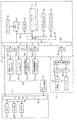
図10は、第2実施例におけるパチンコ機1の電気的構成を示したブロック図である。第2実施例では、各ユニットの総使用時間が、第1実施例における表示LED49(図3参照)に代わり、メカニカルカウンタ61によって表示される。また、そのメカニカルカウンタ61は、各ユニットに対応する数のメカニカルカウンタ61a〜61d備えているため、第1実施例におけるEEPROM43及びスイッチ50が無い構成となっている。
【0062】
表示用制御基板Dは、第1実施例と同様に、主に、MPU41と、ROM42と、ワークRAM71と、ビデオRAM45と、キャラクタROM46と、画像コントローラ47と、入力出力ポート48と、ゲートアレイ70とを備えている。入出力ポート48の入力には、主制御基板Cの出力が接続され、その入出力ポート48の出力は、MPU41、ROM42、ワークRAM71、画像コントローラ47を接続するバスライン51が接続されている。また、入出力ポート48の出力にはメカニカルカウンタ61と液晶表示装置10とがそれぞれコネクタ62〜65及びコネクタ52を介して接続されている。
【0063】
ワークRAM71は、MPU41による各種プログラムの実行時に使用されるワークデータを一時的に記憶するためのメモリであり、インターバルカウンタ71aを備えている。インターバルカウンタ71aは、MPU41により一定時間毎に加算される時間データを記憶するためのメモリであり、この時間データが所定値を越えるとメカニカルカウンタ61へのカウントアップ信号がMPU41によって出力される。
【0064】
メカニカルカウンタ61は、各ユニットの総使用時間を表示するためのものであり、液晶パネルメカニカルカウンタ61aと、バックライトメカニカルカウンタ61bと、表示用制御木案メカニカルカウンタ61cと、液晶制御基板メカニカルカウンタ61dとを備えている。各メカニカルカウンタ61a〜61dは、それぞれコネクタ62〜65を介して表示用制御基板Dの入出力ポート48と分離可能に接続されており、MPU41によって送信されるカウントアップ信号が入力されると、各メカニカルカウンタ61a〜61dの表示部66(図9参照)に表示される表示値が「1」(1時間分)増加する。
【0065】
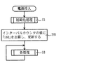
図11は、第2実施例におけるパチンコ機1の表示用制御基板Dにおいて実行されるメイン処理を示したフローチャートである。このメイン処理により画像の表示の制御等の表示用制御基板Dで必要な各処理が実行される。なお、前記した第1実施例と同一の処理には同一のステップ番号を付す。このメイン処理では、まず、第1実施例と同様に、電源投入後、ワークRAM44等の内容を一旦「0」クリアした後に初期値に設定する等といった初期化処理を実行する(S1)。S1の初期化処理の実行後は、ワークRAM71のインターバルカウンタ71aに記憶される時間データに「180」を加算する(S81)。このワークRAM71のインターバルカウンタ71aには、後述するように(図12参照)、10秒毎に時間データ「1」が加算され、その時間データが「360」(1時間分)以上となった場合に、各メカニカルカウンタ61a〜61dへその表示を1時間分だけ増加させるカウントアップ信号が送信される。よって、パチンコ機の電源を切断する毎に、最後のカウントアップ信号の送信時から電源の切断時までの間にワークRAM71のインターバルカウンタ71aに加算された時間データ(「0」〜「360」)が計測されないことになる。この計測されない時間データの値は電源切断毎に異なるが、平均「180」相当の時間データが計測されないことになり、計測した液晶表示装置10の総使用時間の信頼性が低下するという問題がある。そこで、電源が投入される毎にS81の処理を実行することにより、電源切断時に累積した計測誤差を調整することができ、正確な総使用時間を計測することができるのである。なお、本実施例では、S81の処理で加算する時間データを電源の切断時に発生する計測誤差(「0」〜「360」の範囲)の平均値「180」としたが、これより小さい、或いは、大きな時間データを加算するようにしても良い。例えば、時間データ「360」を加算するように構成した場合には、十分に余裕を持ったユニットの使用時間管理を行うことができる。そして、S2の処理の実行後は、表示用制御基板Dで実行される各処理を繰り返す(S3)。
【0066】
図12は、第2実施例におけるパチンコ機1の表示用制御基板Dで10秒毎に実行されるINT割込処理を示したフローチャートである。このINT割込処理は、液晶表示装置10等の使用時間を計測し、その総使用時間をメカニカルカウンタ61へ表示するための処理である。CPU41は、このINT割込処理に関して、ワークRAM71のインターバルカウンタ71aに記憶される時間データに「1」を加算し、その時間データを更新する(S91)。S91の処理を実行後、そのワークRAM71のインターバルカウンタ71aに記憶される時間データの値が「360」以上となったか否かを判断する(S92)。判断の結果、時間データの値が「360」以上となっている場合には(S92:Yes)、各メカニカルカウンタ61a〜61dの表示が前回更新されてから1時間が経過しているので、各メカニカルカウンタ61a〜61dへカウントアップ信号を出力することにより(S93)、各メカニカルカウンタ61a〜61dの表示を1時間分更新する。その後、ワークRAM71のインターバルカウンタ71aに記憶される時間データの値を「0」クリアし(S94)、このINT割込処理を終了する。このINT割込処理は、電源が投入されている間、10秒経過する毎に定期的に繰り返し実行される。これにより、各メカニカルカウンタ61a〜61dの表示が1時間毎に更新され、かかる表示を確認することによって、各ユニットの総使用時間を定量的に把握することができる。
【0067】
このように、メカニカルカウンタ61a〜61dを再利用を判断するユニットに対応する数だけ設けることことにより、電源の供給をすることなく、いずれのユニットが再利用可能であるか否かを判断することができるのである。
【0068】
なお、上記した各実施例において記載した各ユニットの使用時間とは、電源の供給により各ユニットが実際に動作した時間、即ち、通電時間をいう。
【0069】
以上、実施例に基づき本発明を説明したが、本発明は上記実施例に何ら限定される物ではなく、本発明の趣旨を逸脱しない範囲内で種々の改良変形が可能であることは容易に推察できるものである。
【0070】
例えば、第1実施例では、EEPROM43の各メモリ43a〜43dへ、計測した液晶表示装置10等の使用時間が累積加算され、総使用時間として記憶されたが、これに代えて、EEPROM43の各メモリ43a〜43dへ液晶表示装置10等の使用保障時間を予め個別に記憶しておき、その記憶された使用保障時間の値から各装置の使用時間を減算していくことにより、各装置の残余寿命時間として記憶するように構成しても良い。かかる場合には、表示LED49の点灯個数を、初期では全数点灯するように構成し、残余寿命時間が減少するに従い表示LED49の点灯個数を減少させるように構成しても良い。作業者は、この表示LED49の点灯個数を視認することによって、各装置に残された残余寿命時間を容易に認識することができるのである。
【0071】
また、上記各実施例では、表示装置として、液晶を用いた表示装置について説明したが、必ずしもこれに限定されるわけではなく、これに代えて、CRT(ブラウン管)を用いた表示装置としても良いのである。
【0072】
また、第1実施例では、EEPROM43の各メモリに記憶された総使用時間は、押下されたスイッチ50に対応するユニットの総使用時間が表示LED49へ表示されるように構成されたが、表示LED49の代わりに液晶表示装置10へ表示されるように構成しても良い。この場合には、いずれのスイッチ50が押下されても、EEPROM43の各メモリに記憶されたすべてのユニットの総使用時間が同時に表示されるように構成しても良い。液晶表示装置10の広い表示領域を利用することにより、各ユニットの総使用時間を同時に表示することができ、作業者の確認作業の作業性が向上する。
【0073】
また、EEPROM43の各メモリに記憶された総使用時間を表示するタイミングは、表示用制御基板Dに設けられたスイッチ50が押下された場合に限られるわけではなく、例えば、外部から表示命令コマンドを受信した場合にも液晶表示装置10への表示が実行されるように構成しても良い。即ち、スイッチ等の操作により表示用制御基板Dへ表示命令コマンドを送信可能な装置を、更に設けることにより、遊技機1が遊技ホール等に設置されたまま、各ユニットの総使用時間の確認を実行することができる。主制御基板Cから所定のタイミングで表示命令コマンドが表示用制御基板Dへ送信されるようにしても良い。また、例えば、電源が投入された時に、所定時間が経過する間だけ、液晶表示装置へEEPROM43の各メモリに記憶された総使用時間を表示するように構成しても良い。この場合には、煩雑な作業をすることなく液晶表示装置の各ユニットの総使用時間を確認することができる。
【0074】
また、第1実施例では、各ユニットの総使用時間を表示する装置として、3個のLEDからなる表示LED49を用いて説明したが、これに代えて、7セグメントのLEDを用いて、総使用時間を数字で表示するように構成しても良い。この場合、例えば、総使用時間が1万時間未満の場合は「1」を、1万時間以上かつ2万時間未満の場合には「2」が表示される。
【0076】
以下に本発明の変形例を示す。請求項1記載の遊技機において、前記表示装置は、互いに電気的に接続されると共に分離可能な2以上のユニットから構成されており、前記使用時間記憶手段は、前記使用時間計測手段が計測した前記表示装置の使用時間を各ユニット毎に記憶するユニット使用時間記憶手段と、そのユニット使用時間記憶手段が記憶する各ユニットの使用時間を各ユニット毎にクリアするクリア手段と、そのクリア手段を作動させるクリア作動手段とを備え、前記使用時間表示手段は、前記ユニット使用時間記憶手段に記憶された各ユニットの使用時間を表示するユニット使用時間表示手段を備えていることを特徴とする遊技機1。よって、表示装置の使用時間をその表示装置を構成する各ユニット毎に確認することができるので、寿命がそれぞれ異なる各ユニットを効率良く再利用することができる。例えば、回収された遊技機から表示装置を取り外し、他の遊技機に再利用する場合には、各ユニット毎に寿命に達しているか否かをユニット使用時間表示装置によって確認することができる。よって、寿命に達したユニットがある場合には、そのユニットだけを交換することができる。また、この場合には、ユニット使用時間記憶手段に記憶される使用時間の中から、交換したユニットの使用時間だけをクリアすることによって、その交換したユニットの使用時間は、ゼロから新たに計測を開始することができると共に、他のユニットは、引き続きその使用時間の計測を継続することができる。よって、各ユニット毎の使用時間を、正確に計測を行うことができる。
【0077】
遊技機1において、前記クリア作動手段は、前記ユニットと同数のクリアスイッチにより構成され、前記クリア手段は、操作されたクリアスイッチに対応するユニットの使用時間を前記ユニット使用時間記憶手段からクリアすることを特徴とする遊技機2。クリア作動手段は、各ユニット毎に設けられているので、操作者は、煩雑な作業をすることなく、各ユニットに対応するクリア作動手段を操作するだけ使用時間をクリアすることができる。
【0078】
遊技機1又は2において、前記クリア手段は、前記クリアスイッチが所定時間以上継続して操作された場合に作動することを特徴とする遊技機3。クリアスイッチが単に操作されただけでクリア手段が作動してしまうと、操作者の不用意な誤操作によって、ユニット使用時間記録手段に記憶された内容がクリア手段によってクリアされてしまう。これに対し遊技機3では、クリアスイッチが所定時間以上操作された場合に、クリア手段が作動するように構成しているので、操作者が不用意な誤操作によってクリアスイッチを操作してもクリア手段は作動せず、ユニット使用時間記録手段の内容を保持することができる。よって、誤操作などによるクリア手段の作動を回避して、各ユニットの使用時間の記憶を確実に行うことができる。
【0079】
遊技機1から3のいずれかにおいて、前記ユニット使用時間表示手段は、前記ユニット使用時間記憶手段が記憶する各ユニットの使用時間の中から表示する使用時間を選択し、その選択した使用時間を表示するユニット選択表示手段と、そのユニット選択表示手段を作動させるユニット選択表示作動手段とを備えていることを特徴とする遊技機4。ユニット選択表示手段は、各ユニットの中からどのユニットの使用時間を表示するかを選択することができるので、1つのユニット選択表示手段で各ユニットの使用時間を表示することができる。よって、各ユニット毎にその使用時間を表示するための装置を設ける必要がないので、装置を簡略化して、装置コストを低減することができる。
【0080】
遊技機4において、前記表示装置は、前記クリア手段と前記ユニット選択表示手段とを選択的に作動させるスイッチ手段を備えていることを特徴とする遊技機5。1つのスイッチ手段を2つの手段(クリア手段およびユニット選択表示手段)の作動スイッチとして共用するので、スイッチ手段を1つ省略できる分、装置を簡略化して、装置コストを低減することができる。
【0081】
遊技機5において、前記スイッチ手段は押しボタンで構成されており、前記ユニット選択表示手段はその押しボタンを第1の所定時間押下し続けた場合に作動すると共に、前記クリア手段はその押しボタンを前記第1の所定時間より長い第2の所定時間押下し続けた場合に作動することを特徴とする遊技機6。クリア手段は、第1の所定時間より長い第2の所定時間押下した場合にしか作動することができないので、操作者の不用意な誤操作によってもクリア手段が簡単に作動してしまうことを防止することができる。
【0082】
遊技機1から6のいずれかにおいて、前記ユニット使用時間表示手段は、発光可能に構成された複数の発光体を有し、前記ユニット使用時間記憶手段が記憶する使用時間の値に応じて前記複数の発光体の発光数を増減可能な発光表示手段を備えていることを特徴とする遊技機7。発光体の発光数によって使用時間が表示されるように構成されているので、発光体の発光数を確認することによって、容易に使用時間を認知することができる。また、数字を用いて使用時間を表示するように構成する場合に比べて、装置を簡略化することができ、装置コストを低減することができる。
【0083】
遊技機7において、前記発光表示手段は、その使用時間が表示されるユニットの種類に応じて、使用時間の値と発光させる発光体の発光数との比率を変化させる発光変更手段を備えていることを特徴とする遊技機8。各ユニットの寿命が大きく異なる場合にも、最長の寿命を有するユニットの使用時間をより少ない発光体の発光数で表示することができる。よって、発光体の個数が増加することを防止することができる分、装置を簡略化し、装置コストを低減することができる。
【0084】
遊技機7又は8において、前記発光体はLEDによって構成されていることを特徴とする遊技機8。コストが低く、優れた寿命特性を有するLEDを使用することにより、装置コストを低減できると共に、安定した使用時間の表示を行うことができる。
【0085】
遊技機1において、前記ユニット使用時間記憶手段は、電源が投入された場合に、各ユニット毎に記憶する使用時間の値に所定の時間を加算する加算手段を備えていることを特徴とする遊技機9。電源を切断する毎に累積される使用時間の誤差を調整することができるので、使用時間を正確に計測することができる。
【0086】
遊技機1において、前記ユニット使用時間表示手段は、電源切断後も使用時間の表示が可能なメカニカルカウンタを備えていることを特徴とする遊技機10。よって、電源切断後も使用時間の表示が維持されるので、表示装置の再利用工程において、電源を再投入するなどの作業をする必要がなく、容易に各ユニットの使用時間を確認することができる。
【0087】
遊技機10において、前記メカニカルカウンタは、前記ユニット使用時間記憶手段を兼ねていることを特徴とする遊技機11。よって、電源切断後も使用時間の記憶を維持することができる。また、使用時間を記憶しておくための装置を別途設けておく必要がないので、装置を簡略化して、装置コストを低減することができる。
【0088】
遊技機10又は11において、少なくとも使用時間計測手段を格納するケース体を備えており、前記メカニカルカウンタは、そのケース体に装着されていることを特徴とする遊技機12。メカニカルカウンタは、表示装置を構成する各ユニットに対して長い寿命を有している。その為、このメカニカルカウンタがケース体に装着されることにより、ケース体に格納されている各ユニットが寿命等により順次交換される場合にも、ケース体及びメカニカルカウンタをそのまま使用しつづけることができる。よって、表示装置を有効に再利用することができる。
【0089】
遊技機10から12のいずれかににおいて、前記ユニット使用時間表示手段は、電源が投入された場合に、前記メカニカルカウンタの表示を所定の時間分だけ更新する更新手段を備えていることを特徴とする遊技機13。電源を切断する毎に累積される使用時間の誤差を調整することができるので、使用時間を正確に知ることができる。
【0090】
遊技機1において、遊技の制御を行う主制御基板と、その主制御手段からの命令に従って画像の表示を制御する表示用制御基板とを備え、前記ユニット使用時間計測手段、ユニット使用時間記憶手段、及び、ユニット使用時間表示手段は、前記表示用制御基板に設けられていることを特徴とする遊技機14。表示用制御基板は表示装置の各ユニットに対して十分長い寿命を有している。よって、前記ユニット使用時間計測手段、ユニット使用時間記憶手段、及び、ユニット使用時間表示手段を有効に再利用することができる。
【0091】
請求項1記載の遊技機または遊技機1から14のいずれかにおいて、前記遊技機はパチンコ機であることを特徴とする遊技機15。中でも、パチンコ機の基本構成としては操作ハンドルを備え、その操作ハンドルの操作に応じて球を所定の遊技領域へ発射し、球が遊技領域内の所定の位置に配設された作動口に入賞(又は作動口を通過)することを必要条件として、表示装置において変動表示されている識別情報が所定時間後に確定停止されるものが挙げられる。また、特別遊技状態の出力時には、遊技領域内の所定の位置に配設された可変入賞装置(特定入賞口)が所定の態様で開放されて球を入賞可能とし、その入賞個数に応じた有価価値(景品球のみならず、磁気カードへ書き込まれる情報等も含む)が付与されるものが挙げられる。
【0092】
請求項1記載の遊技機または遊技機1から14のいずれかにおいて、前記遊技機はスロットマシンであることを特徴とする遊技機16。中でも、スロットマシンの基本構成としては、「複数の識別情報からなる識別情報列を変動表示した後に識別情報を確定表示する可変表示手段を備え、始動用操作手段(例えば操作レバー)の操作に起因して、或いは、所定時間経過することにより、識別情報の変動が停止され、その停止時の確定識別情報が特定識別情報であることを必要条件として、遊技者に有利な特別遊技状態を出力させる特別遊技状態出力手段とを備えた遊技機」となる。この場合、遊技媒体はコイン、メダル等が代表例として挙げられる。
【0093】
請求項1記載の遊技機または遊技機1から14のいずれかにおいて、前記遊技機はパチンコ機とスロットマシンとを融合させたものであることを特徴とする遊技機17。中でも、融合させた遊技機の基本構成としては、「複数の識別情報からなる識別情報列を変動表示した後に識別情報を確定表示する可変表示手段を備え、始動用操作手段(例えば操作レバー)の操作に起因して識別情報の変動が開始され、停止用操作手段(例えばストップボタン)の操作に起因して、或いは、所定時間経過することにより識別情報の変動が停止され、その停止時の確定識別情報が特定識別情報であることを必要条件として、遊技者に有利な特別遊技状態を出力させる特別遊技状態出力手段とを備え、遊技媒体として球を使用すると共に、前記識別情報の変動開始に際しては所定数の球を必要とし、特別遊技状態の出力に際しては多くの球が払い出されるように構成されている遊技機」となる。
【0094】
【発明の効果】
請求項1記載の遊技機によれば、遊技に伴う識別情報の動的表示を行う表示手段を備え、電源断時において前記表示手段の使用時間に応じた値を保持可能な使用時間記憶手段と、電源入時において一定の時間が経過する毎に前記使用時間記憶手段に記憶される値を更新する更新手段と、その更新手段によって更新された前記使用時間記憶手段に記憶される値に基づいて、前記表示手段の使用時間に関する情報を報知する使用時間報知手段と、電源が投入された場合に、前記更新手段による更新が行われてから前記表示手段が前記一定の時間またはそれよりも短い時間であって0より長い特定の時間使用されたものとして、前記使用時間記憶手段に記憶される値を補正する使用時間補正手段とを備えているので、表示手段の交換時期を適正に把握できるという効果がある。
【図面の簡単な説明】
【図1】 本発明の第1実施例におけるパチンコ機およびカード読取ユニットの正面図である。
【図2】 パチンコ機に搭載される液晶表示装置を各ユニット毎に分解して示した斜視図である。
【図3】 パチンコ機の電気的構成を示したブロック図である。
【図4】 パチンコ機の表示用制御基板において実行されるメイン処理を示したフローチャートである。
【図5】 パチンコ機の表示用制御基板で10秒毎に実行されるINT割込処理を示したフローチャートである。
【図6】 パチンコ機の表示用制御基板で実行される使用時間表示処理のフローチャートである。
【図7】 パチンコ機の表示用制御基板で実行される液晶パネルスイッチ処理を示したフローチャートである。
【図8】 パチンコ機の表示用制御基板で実行されるバックライトスイッチ処理を示したフローチャートである。
【図9】 第2実施例におけるパチンコ機に搭載される液晶表示装置を各ユニット毎に分解して示した斜視図である。
【図10】 第2実施例におけるパチンコ機の電気的構成を示したブロック図である。
【図11】 第2実施例におけるパチンコ機の表示用制御基板において実行されるメイン処理を示したフローチャートである。
【図12】 第2実施例におけるパチンコ機の表示用制御基板で10秒毎に実行されるINT割込処理を示したフローチャートである。
【符号の説明】
1 パチンコ機
10,60 液晶表示装置(表示手段)
43 EEPROM(使用時間記憶手段)
49 表示LED(使用時間報知手段の一部)
61 メカニカルカウンタ(使用時間記憶手段、使用時間報知手段)
71a インターバルカウンタ(使用時間補正手段の一部)
S2 使用時間補正手段
S81 使用時間補正手段の一部
S91〜S94 更新手段、使用時間補正手段の一部
S32〜S34 使用時間報知手段の一部[0001]
BACKGROUND OF THE INVENTION
The present invention relates to gaming machines such as pachinko machines and slot machines.
[0002]
[Prior art]
In recent years, in gaming machines such as pachinko machines, liquid crystal display devices have been developed in order to improve the fun of gaming.Display means such asThe one that uses is becoming mainstream.
[0004]
[Problems to be solved by the invention]
Here, when replacing the display means, etc.,Display meansActual usage timeQuantitativelyIf there is no way to grasp, I do not know the proper replacement timeThere was a problem.
[0005]
The present inventionExampleProblemsetcIt was made to solveDisplay meansofProper replacement timeHoldGripCanRuThe purpose is to provide a gaming machine.
[0006]
[Means for Solving the Problems]
In order to achieve this object, the gaming machine according to claim 1 includes display means for dynamically displaying identification information associated with the game, and can hold a value corresponding to the usage time of the display means when the power is turned off. Use time storage means and power-onEvery time a certain amount of time passesUpdate means for updating the value stored in the use time storage means, and use for notifying information on the use time of the display means based on the value stored in the use time storage means updated by the update means The time notification means and the display means after the update by the update means when the power is turned on.A specific time that is longer than 0 or less than the certain timeIt is provided with use time correction means for correcting the value stored in the use time storage means as used.
[0008]
DETAILED DESCRIPTION OF THE INVENTION
Hereinafter, preferred embodiments of the present invention will be described with reference to the accompanying drawings. FIG. 1 is a front view of the pachinko machine 1 and the
[0009]
A substantially arc-shaped outer rail 6 is planted on the front surface of the
[0010]
A
[0011]
Below the variable display device 11, a symbol operation port (first type start port) 12 is disposed. When the game ball passes through the symbol operation port 12, the first type start port switch (not shown) is turned on to start the variable display of the variable display device 11, and the six game balls are awarded. It is paid out as a ball. A variable winning
[0012]
The opening 13b of the big prize opening constitutes a part of the big prize opening, and the display result after the change of the variable display device 11 coincides with one of a predetermined combination of symbols (a jackpot display). In addition, the game balls are released until a predetermined time (for example, 30 seconds) elapses or a predetermined number (for example, 10) of game balls wins in the opening 13b of the big prize opening so that the game balls can be easily won. Is. A state in which the opening / closing operation of the opening 13b of the special prize opening can be performed is a state in which a predetermined game value is given (special game state).
[0013]
An opening /
[0014]
An outro 14 is formed below the variable winning
[0015]
The above-described upper plate 16 includes a
[0016]
On the left side of the pachinko machine 1 configured as described above, a
[0017]
Amount setting button for setting a loan amount based on the balance amount data recorded on the card at a position between the
[0018]
A pair of upper and lower connecting table
[0019]
FIG. 2 is an exploded perspective view showing the liquid
[0020]
The liquid
[0021]
The
[0022]
The liquid crystal control board L is for controlling the translucency of the liquid crystal cell by applying a voltage to the drive electrode of the liquid crystal cell of the
[0023]
The display control board D is for controlling the display of variation of symbols by the liquid
[0024]
As described above, the liquid
[0025]
FIG. 3 is a block diagram showing the electrical configuration of the pachinko machine 1. The pachinko machine 1 mainly includes a main control board C that controls the progress of the game and a display control board D that controls the display of the liquid crystal liquid
[0026]
The main control board C has an
[0027]
The display control board D is a control board for controlling the variable display of symbols by the liquid
[0028]
The
[0029]
The
[0030]
The
[0031]
The liquid
[0032]
Next, each process executed by the pachinko machine 1 configured as described above will be described with reference to the flowcharts of FIGS. FIG. 4 is a flowchart showing a main process executed on the display control board D of the pachinko machine 1. By this main process, each process necessary for the display control board D, such as control of image display, is executed. In this main process, first, after the power is turned on, an initialization process is executed such that the contents of the
[0033]
FIG. 5 is a flowchart showing an INT interrupt process executed at regular intervals on the display control board D of the pachinko machine 1. This INT interruption process is a process for measuring the usage time of the liquid
[0034]
When the memory for storing the total use time data is configured by the EEPROM as shown in the present embodiment, the fixed time interval at which the above INT interrupt processing is executed is set to about 1 hour, for example. Is desirable. At present, the number of write guarantees of a commonly used EEPROM is about 100,000 times. Therefore, even when the gaming machine is continuously used, the writing process can be executed every hour over a period of 10 years or more, which is sufficient as a period for measuring the usage time of the liquid
[0035]
FIG. 6 is a flowchart of a usage time display process executed on the display control board D of the pachinko machine 1. In this usage time display processing, the total usage time data of the units corresponding to the pressed
[0036]
In the usage time display process, first, it is determined whether any of the
[0037]
If it is determined in the process of S21 that any one of the
[0038]
On the other hand, in the process of S22, when the pressed switch is the backlight switch 50b (S22: backlight switch), the process to be executed is a process of displaying the usage time of the
[0039]
In the process of S22, when the pressed
[0040]
In the process of S22, when the pressed
[0041]
Here, the liquid crystal panel switch process that is the process of S23 is a process that is executed according to the flowchart shown in FIG. 7, and the backlight switch process that is the process of S23 is a process that is executed according to the flowchart shown in FIG. .
[0042]
FIG. 7 is a flowchart showing a liquid crystal panel switch process executed on the display control board D of the pachinko machine 1. The liquid crystal panel switch process (S23) is executed when the liquid
[0043]
In the liquid crystal panel switch process, first, the pressed state of the liquid
[0044]
On the other hand, when the total use time data value of the
[0045]
When the total use time data value of the
[0046]
When the total use time data value of the
[0047]
In the process of S31, when the pressing time of the liquid
[0048]
After executing the process of S40, the first to
[0049]
FIG. 8 is a flowchart showing a backlight switch process executed on the display control board D of the pachinko machine 1. The backlight switch process (S24) is executed when the backlight switch 50b is pressed, and the usage time of the
[0050]
In the backlight switch process, first, the pressing state of the backlight switch 50b is confirmed (S51). When the pressing time of the backlight switch 50b is less than 5 seconds (S51: No), the value of the total usage time data stored in the
[0051]
On the other hand, when the total use time data value of the
[0052]
When the value of the total use time data of the
[0053]
When the total use time data value of the
[0054]
In the liquid crystal panel switch processing (see FIG. 7), all the
[0055]
On the other hand, in the process of S51, when the pressing time of the backlight switch 50b is 5 seconds or more (S51: Yes), the total use time data stored in the
[0056]
As described above, the total usage time in which the liquid
[0057]
Next, a second embodiment will be described with reference to FIG. In the pachinko machine 1 of the first embodiment, the total use time of each unit is displayed by the
[0058]
FIG. 9 is an exploded perspective view showing the liquid
[0059]
The
[0060]
When the liquid
[0061]
FIG. 10 is a block diagram showing an electrical configuration of the pachinko machine 1 in the second embodiment. In the second embodiment, the total usage time of each unit is displayed by the
[0062]
Similar to the first embodiment, the display control board D mainly includes an
[0063]
The
[0064]
The
[0065]
FIG. 11 is a flowchart showing a main process executed in the display control board D of the pachinko machine 1 in the second embodiment. By this main process, each process necessary for the display control board D, such as control of image display, is executed. The same step numbers are assigned to the same processes as those in the first embodiment. In this main process, first, as in the first embodiment, after the power is turned on, an initialization process is executed such that the contents of the
[0066]
FIG. 12 is a flowchart showing an INT interrupt process executed every 10 seconds on the display control board D of the pachinko machine 1 in the second embodiment. This INT interruption process is a process for measuring the usage time of the liquid
[0067]
In this way, by providing the
[0068]
Note that the usage time of each unit described in each of the above embodiments refers to the time during which each unit actually operates by supplying power, that is, the energization time.
[0069]
The present invention has been described based on the embodiments. However, the present invention is not limited to the above embodiments, and various modifications can be easily made without departing from the spirit of the present invention. It can be guessed.
[0070]
For example, in the first embodiment, the measured use time of the liquid
[0071]
In each of the above-described embodiments, the display device using liquid crystal has been described as the display device. However, the display device is not necessarily limited to this, and a display device using a CRT (CRT) may be used instead. It is.
[0072]
Further, in the first embodiment, the total usage time stored in each memory of the
[0073]
Further, the timing for displaying the total usage time stored in each memory of the
[0074]
Further, in the first embodiment, the
[0076]
The modification of this invention is shown below. 2. The gaming machine according to claim 1, wherein the display device is composed of two or more units that are electrically connected to each other and are separable, and the usage time storage means is measured by the usage time measurement means. Operates the unit usage time storage means for storing the usage time of the display unit for each unit, the clear means for clearing the usage time of each unit stored in the unit usage time storage means for each unit, and the clear means And a clear operation means for causing the usage time display means to include a unit usage time display means for displaying the usage time of each unit stored in the unit usage time storage means. . Accordingly, since the usage time of the display device can be confirmed for each unit constituting the display device, each unit having a different lifetime can be efficiently reused. For example, when the display device is removed from the collected gaming machine and reused for another gaming machine, it can be confirmed by the unit usage time display device whether the life of each unit has been reached. Therefore, if there is a unit that has reached the end of its life, only that unit can be replaced. In this case, the usage time of the replaced unit is newly measured from zero by clearing only the usage time of the replaced unit from the usage times stored in the unit usage time storage means. Other units can continue to measure their usage time as they can begin. Therefore, the usage time for each unit can be accurately measured.
[0077]
In the gaming machine 1, the clear operation means is configured by the same number of clear switches as the unit, and the clear means clears the use time of the unit corresponding to the operated clear switch from the unit use time storage means. A gaming machine 2 characterized by this. Since the clear operation means is provided for each unit, the operator can clear the use time only by operating the clear operation means corresponding to each unit without performing complicated work.
[0078]
In the gaming machine 1 or 2, the clearing unit operates when the clear switch is operated continuously for a predetermined time or more. If the clearing means is activated simply by operating the clear switch, the contents stored in the unit usage time recording means are cleared by the clearing means due to careless operation by the operator. On the other hand, the gaming machine 3 is configured such that the clearing unit is activated when the clearing switch is operated for a predetermined time or longer, so that the clearing unit can be operated even if the operator operates the clearing switch by careless operation. Does not operate and the contents of the unit usage time recording means can be retained. Therefore, the operation of the clearing means due to an erroneous operation or the like can be avoided, and the usage time of each unit can be reliably stored.
[0079]
In any one of the gaming machines 1 to 3, the unit usage time display means selects a usage time to be displayed from the usage times of each unit stored in the unit usage time storage means, and displays the selected usage time. A gaming machine 4 comprising: unit selection display means for operating and unit selection display operation means for operating the unit selection display means. Since the unit selection display means can select which unit's usage time is to be displayed from among the units, the single unit selection display means can display the usage time of each unit. Therefore, since it is not necessary to provide a device for displaying the usage time for each unit, the device can be simplified and the device cost can be reduced.
[0080]
In the gaming machine 4, the display device includes a switch unit that selectively activates the clearing unit and the unit selection display unit, wherein one switching unit includes two units ( Since it is shared as an operation switch for the clearing unit and the unit selection display unit), the device can be simplified and the device cost can be reduced by the amount that one switch unit can be omitted.
[0081]
In the
[0082]
In any one of the gaming machines 1 to 6, the unit usage time display means includes a plurality of light emitters configured to be capable of emitting light, and the plurality of unit usage time display means according to a value of usage time stored in the unit usage time storage means. A gaming machine comprising a light emission display means capable of increasing or decreasing the number of light emission of the light emitters. Since the usage time is displayed according to the number of light emission of the light emitter, the usage time can be easily recognized by confirming the number of light emission of the light emitter. Further, the apparatus can be simplified and the apparatus cost can be reduced as compared with the case where the usage time is displayed using numerals.
[0083]
In the gaming machine 7, the light emission display means includes light emission changing means for changing a ratio between the value of the usage time and the number of light emission of the light emitting body to emit according to the type of the unit for which the usage time is displayed. A gaming machine 8 characterized by that. Even when the lifespan of each unit is greatly different, the usage time of the unit having the longest lifespan can be displayed with a smaller number of light emitters. Therefore, the apparatus can be simplified and the apparatus cost can be reduced by the amount that the increase in the number of light emitters can be prevented.
[0084]
In the gaming machine 7 or 8, the light emitter is constituted by an LED. By using an LED having a low cost and excellent lifetime characteristics, the device cost can be reduced and a stable usage time can be displayed.
[0085]
In the gaming machine 1, the unit usage time storage means includes addition means for adding a predetermined time to the usage time value stored for each unit when the power is turned on.
[0086]
In the gaming machine 1, the unit usage time display means includes a mechanical counter capable of displaying the usage time even after the power is turned off. Therefore, since the display of the usage time is maintained even after the power is turned off, it is not necessary to perform operations such as turning on the power again in the process of reusing the display device, and the usage time of each unit can be easily confirmed. it can.
[0087]
In the
[0088]
The
[0089]
In any of the
[0090]
The gaming machine 1 includes a main control board that controls a game and a display control board that controls display of an image in accordance with a command from the main control means, the unit usage time measuring means, the unit usage time storage means, The gaming machine 14 is characterized in that the unit usage time display means is provided on the display control board. The display control board has a sufficiently long life for each unit of the display device. Therefore, the unit usage time measuring unit, the unit usage time storage unit, and the unit usage time display unit can be effectively reused.
[0091]
15. The
[0092]
15. The gaming machine 16 according to claim 1, wherein the gaming machine is a slot machine. Above all, the basic configuration of the slot machine is “variable display means for confirming and displaying the identification information after variably displaying the identification information string composed of a plurality of identification information, and resulting from the operation of the starting operation means (for example, the operation lever) Alternatively, when a predetermined time elapses, the fluctuation of the identification information is stopped, and a special gaming state advantageous to the player is output on the condition that the fixed identification information at the time of the stop is the specific identification information. A gaming machine provided with a special gaming state output means. In this case, examples of the game media include coins and medals.
[0093]
15. The
[0094]
【The invention's effect】
According to the gaming machine of claim 1, a display unit that dynamically displays identification information associated with a game, and a usage time storage unit that can hold a value corresponding to the usage time of the display unit when the power is turned off; When the power is turned onEvery time a certain amount of time passesUpdate means for updating the value stored in the use time storage means, and use for notifying information on the use time of the display means based on the value stored in the use time storage means updated by the update means The time notification means and the display means after the update by the update means when the power is turned on.A specific time that is longer than 0 or less than the certain timeSince it has used time correction means for correcting the value stored in the use time storage means as used, there is an effect that it is possible to properly grasp the replacement time of the display means.
[Brief description of the drawings]
FIG. 1 is a front view of a pachinko machine and a card reading unit according to a first embodiment of the present invention.
FIG. 2 is an exploded perspective view of a liquid crystal display device mounted on a pachinko machine for each unit.
FIG. 3 is a block diagram showing an electrical configuration of the pachinko machine.
FIG. 4 is a flowchart showing a main process executed on a display control board of the pachinko machine.
FIG. 5 is a flowchart showing an INT interrupt process executed every 10 seconds on the display control board of the pachinko machine.
FIG. 6 is a flowchart of a usage time display process executed on the display control board of the pachinko machine.
FIG. 7 is a flowchart showing a liquid crystal panel switch process executed on the display control board of the pachinko machine.
FIG. 8 is a flowchart showing a backlight switch process executed on the display control board of the pachinko machine.
FIG. 9 is an exploded perspective view of each unit of a liquid crystal display device mounted on a pachinko machine according to a second embodiment.
FIG. 10 is a block diagram showing an electrical configuration of a pachinko machine in the second embodiment.
FIG. 11 is a flowchart showing a main process executed on the display control board of the pachinko machine in the second embodiment.
FIG. 12 is a flowchart showing an INT interrupt process executed every 10 seconds on the display control board of the pachinko machine in the second embodiment.
[Explanation of symbols]
1 Pachinko machine
10, 60 Liquid crystal display device (display means)
43 EEPROM (usage time storage means)
49 Display LED (part of usage time notification means)
61 Mechanical counter (use time storage means, use time notification means)
71a Interval counter (part of usage time correction means)
S2 Usage time correction means
S81 Part of usage time correction means
S91-S94 Update means, part of usage time correction means
S32-S34 Part of usage time notification means
Claims (1)
電源断時において前記表示手段の使用時間に応じた値を保持可能な使用時間記憶手段と、
電源入時において一定の時間が経過する毎に前記使用時間記憶手段に記憶される値を更新する更新手段と、
その更新手段によって更新された前記使用時間記憶手段に記憶される値に基づいて、前記表示手段の使用時間に関する情報を報知する使用時間報知手段と、
電源が投入された場合に、前記更新手段による更新が行われてから前記表示手段が前記一定の時間またはそれよりも短い時間であって0より長い特定の時間使用されたものとして、前記使用時間記憶手段に記憶される値を補正する使用時間補正手段とを備えているものであることを特徴とする遊技機。In a gaming machine provided with a display means for performing dynamic display of identification information associated with a game,
Usage time storage means capable of holding a value corresponding to the usage time of the display means when the power is turned off;
Updating means for updating a value stored in the usage time storage means every time a predetermined time elapses when the power is turned on;
Based on the value stored in the usage time storage means updated by the updating means, usage time notification means for notifying information on the usage time of the display means;
When the power is turned on, it is assumed that the display means has been used for a specific time longer than 0 for a certain time or a shorter time since the update by the update means. A gaming machine comprising a usage time correction unit that corrects a value stored in the storage unit.
Priority Applications (1)
| Application Number | Priority Date | Filing Date | Title |
|---|---|---|---|
| JP2000374181A JP4961631B2 (en) | 2000-12-08 | 2000-12-08 | Game machine |
Applications Claiming Priority (1)
| Application Number | Priority Date | Filing Date | Title |
|---|---|---|---|
| JP2000374181A JP4961631B2 (en) | 2000-12-08 | 2000-12-08 | Game machine |
Related Child Applications (1)
| Application Number | Title | Priority Date | Filing Date |
|---|---|---|---|
| JP2011167503A Division JP2011235174A (en) | 2011-07-29 | 2011-07-29 | Game machine |
Publications (3)
| Publication Number | Publication Date |
|---|---|
| JP2002172256A JP2002172256A (en) | 2002-06-18 |
| JP2002172256A5 JP2002172256A5 (en) | 2008-01-24 |
| JP4961631B2 true JP4961631B2 (en) | 2012-06-27 |
Family
ID=18843418
Family Applications (1)
| Application Number | Title | Priority Date | Filing Date |
|---|---|---|---|
| JP2000374181A Expired - Lifetime JP4961631B2 (en) | 2000-12-08 | 2000-12-08 | Game machine |
Country Status (1)
| Country | Link |
|---|---|
| JP (1) | JP4961631B2 (en) |
Families Citing this family (6)
| Publication number | Priority date | Publication date | Assignee | Title |
|---|---|---|---|---|
| JP2009119196A (en) * | 2007-11-19 | 2009-06-04 | Sammy Corp | Game machine |
| JP2009165850A (en) * | 2009-03-23 | 2009-07-30 | Sanyo Product Co Ltd | Game machine |
| JP5576089B2 (en) * | 2009-10-22 | 2014-08-20 | 京楽産業.株式会社 | An accessory control board and a pachinko machine |
| JP5617825B2 (en) * | 2011-11-23 | 2014-11-05 | 株式会社三洋物産 | Game machine |
| JP5678985B2 (en) * | 2013-04-30 | 2015-03-04 | 株式会社三洋物産 | Game machine |
| JP2016063960A (en) * | 2014-09-24 | 2016-04-28 | 京楽産業.株式会社 | Game machine |
Family Cites Families (9)
| Publication number | Priority date | Publication date | Assignee | Title |
|---|---|---|---|---|
| JPS6275627A (en) * | 1985-09-30 | 1987-04-07 | Toshiba Corp | Warning device |
| JP2876744B2 (en) * | 1990-08-16 | 1999-03-31 | オムロン株式会社 | Hygrometer |
| JP2775682B2 (en) * | 1993-03-29 | 1998-07-16 | 豊丸産業株式会社 | Pachinko machine |
| JPH06308891A (en) * | 1993-04-23 | 1994-11-04 | Matsushita Electric Ind Co Ltd | Display device |
| US5676824A (en) * | 1994-09-30 | 1997-10-14 | Samsung Electronics Co., Ltd. | Water purifier with means for indicating when filter replacement is due and for automatically initiating a membrane washing step |
| JPH10127906A (en) * | 1996-10-31 | 1998-05-19 | Sankyo Kk | Game machine system |
| JPH10328398A (en) * | 1997-05-28 | 1998-12-15 | Taiyo Elec Co Ltd | Game hall equipment and game machine |
| JPH11262761A (en) * | 1998-03-19 | 1999-09-28 | Mitsubishi Electric Corp | Bathwater circulating apparatus |
| JP2000271388A (en) * | 1999-03-26 | 2000-10-03 | Nippon Kentetsu Co Ltd | Washing machine |
-
2000
- 2000-12-08 JP JP2000374181A patent/JP4961631B2/en not_active Expired - Lifetime
Also Published As
| Publication number | Publication date |
|---|---|
| JP2002172256A (en) | 2002-06-18 |
Similar Documents
| Publication | Publication Date | Title |
|---|---|---|
| JP5462328B2 (en) | Game machine | |
| JP2000334088A5 (en) | ||
| JP2008061749A (en) | Game machine | |
| JP4961631B2 (en) | Game machine | |
| JP5512746B2 (en) | Game machine | |
| JP2017051842A (en) | Game machine | |
| JP6042152B2 (en) | Game machine | |
| JP5512747B2 (en) | Game machine | |
| JP5761277B2 (en) | Game machine | |
| JP6088774B2 (en) | Game machine | |
| JP2011235174A (en) | Game machine | |
| JP6118740B2 (en) | Game machine | |
| JP2019010335A (en) | Game machine | |
| JP6008883B2 (en) | Game machine | |
| JP5745472B2 (en) | Game machine | |
| JP6286500B2 (en) | Game machine | |
| JP2008228998A (en) | Game machine | |
| JP6068550B2 (en) | Game machine | |
| JP4583548B2 (en) | Game machine | |
| JP6043746B2 (en) | Game machine | |
| JP6244442B2 (en) | Game machine | |
| JP5109057B2 (en) | Amusement stand | |
| JP2008029500A (en) | Game machine | |
| JP4583547B2 (en) | Game machine | |
| JP4979979B2 (en) | Game machine |
Legal Events
| Date | Code | Title | Description |
|---|---|---|---|
| RD02 | Notification of acceptance of power of attorney |
Free format text: JAPANESE INTERMEDIATE CODE: A7422 Effective date: 20070221 |
|
| A521 | Written amendment |
Free format text: JAPANESE INTERMEDIATE CODE: A523 Effective date: 20071204 |
|
| A621 | Written request for application examination |
Free format text: JAPANESE INTERMEDIATE CODE: A621 Effective date: 20071204 |
|
| A131 | Notification of reasons for refusal |
Free format text: JAPANESE INTERMEDIATE CODE: A131 Effective date: 20100921 |
|
| A521 | Written amendment |
Free format text: JAPANESE INTERMEDIATE CODE: A523 Effective date: 20101119 |
|
| A131 | Notification of reasons for refusal |
Free format text: JAPANESE INTERMEDIATE CODE: A131 Effective date: 20110531 |
|
| A521 | Written amendment |
Free format text: JAPANESE INTERMEDIATE CODE: A523 Effective date: 20110729 |
|
| TRDD | Decision of grant or rejection written | ||
| A01 | Written decision to grant a patent or to grant a registration (utility model) |
Free format text: JAPANESE INTERMEDIATE CODE: A01 Effective date: 20120228 |
|
| A01 | Written decision to grant a patent or to grant a registration (utility model) |
Free format text: JAPANESE INTERMEDIATE CODE: A01 |
|
| A61 | First payment of annual fees (during grant procedure) |
Free format text: JAPANESE INTERMEDIATE CODE: A61 Effective date: 20120312 |
|
| R150 | Certificate of patent or registration of utility model |
Free format text: JAPANESE INTERMEDIATE CODE: R150 Ref document number: 4961631 Country of ref document: JP Free format text: JAPANESE INTERMEDIATE CODE: R150 |
|
| FPAY | Renewal fee payment (event date is renewal date of database) |
Free format text: PAYMENT UNTIL: 20150406 Year of fee payment: 3 |
|
| R250 | Receipt of annual fees |
Free format text: JAPANESE INTERMEDIATE CODE: R250 |
|
| R250 | Receipt of annual fees |
Free format text: JAPANESE INTERMEDIATE CODE: R250 |
|
| R250 | Receipt of annual fees |
Free format text: JAPANESE INTERMEDIATE CODE: R250 |
|
| R250 | Receipt of annual fees |
Free format text: JAPANESE INTERMEDIATE CODE: R250 |
|
| R250 | Receipt of annual fees |
Free format text: JAPANESE INTERMEDIATE CODE: R250 |
|
| R250 | Receipt of annual fees |
Free format text: JAPANESE INTERMEDIATE CODE: R250 |
|
| EXPY | Cancellation because of completion of term |