JP4956102B2 - Zoom lens and imaging apparatus having the same - Google Patents
Zoom lens and imaging apparatus having the same Download PDFInfo
- Publication number
- JP4956102B2 JP4956102B2 JP2006243938A JP2006243938A JP4956102B2 JP 4956102 B2 JP4956102 B2 JP 4956102B2 JP 2006243938 A JP2006243938 A JP 2006243938A JP 2006243938 A JP2006243938 A JP 2006243938A JP 4956102 B2 JP4956102 B2 JP 4956102B2
- Authority
- JP
- Japan
- Prior art keywords
- lens
- refractive power
- refractive index
- zoom
- zoom lens
- Prior art date
- Legal status (The legal status is an assumption and is not a legal conclusion. Google has not performed a legal analysis and makes no representation as to the accuracy of the status listed.)
- Expired - Fee Related
Links
Images


Description
本発明はスチルカメラやビデオカメラ、そしてデジタルスチルカメラ等に好適なズームレンズ及びそれを有する撮像装置に関するものである。 The present invention relates to a zoom lens suitable for a still camera, a video camera, a digital still camera, and the like, and an imaging apparatus having the same.
最近、固体撮像素子を用いたビデオカメラ、デジタルスチルカメラ等の撮像装置(カメラ)には、高機能であること、そしてカメラ全体がコンパクト(小型)であることが要望されている。そしてそれに伴い、これらのカメラに用いる光学系(撮像光学系)には、レンズ枚数が少なく、小型で、しかも高い光学性能を有するズームレンズであることが求められている。 Recently, an imaging apparatus (camera) such as a video camera or a digital still camera using a solid-state imaging device is required to have high functionality and to be compact (small) as a whole. Accordingly, an optical system (imaging optical system) used for these cameras is required to be a zoom lens having a small number of lenses, a small size, and high optical performance.
この種のカメラには、レンズ最後部と撮像素子との間に、ローパスフィルターや色補正フィルターなどの各種の光学部材が配置される。この為、それに用いるズームレンズには、比較的バックフォーカスが長いことが要求される。 In this type of camera, various optical members such as a low-pass filter and a color correction filter are disposed between the last lens portion and the image sensor. For this reason, the zoom lens used therefor is required to have a relatively long back focus.
更に、カラー画像用の撮像素子を用いたカラーカメラの場合には、色のシェーディングを避けるため、像側がテレセントリックであることが要求されている。 Furthermore, in the case of a color camera using a color image pickup device, the image side is required to be telecentric in order to avoid color shading.
バックフォーカスが長く、像側のテレセントリック特性の良いズームレンズとして、物体側より像側へ順に、負の屈折力の第1レンズ群、正の屈折力の第2レンズ群、及び正の屈折力の第3レンズ群より成る3群ズームレンズが知られている(特許文献1、2)。
As a zoom lens with a long back focus and good telecentric characteristics on the image side, in order from the object side to the image side, a first lens group having a negative refractive power, a second lens group having a positive refractive power, and a positive refractive power A three-group zoom lens composed of a third lens group is known (
一方、レンズ内部での屈折率が一様でない材料より成る屈折率分布型レンズが知られている。 On the other hand, a gradient index lens made of a material having a non-uniform refractive index inside the lens is known.
屈折率分布型レンズでは、レンズ境界面で光線が屈折する光学作用の他に、光線が屈折率分布媒質中を伝播するときに受ける光学作用が加わる。このため、屈折率が一様な材料より成る均質レンズと比べて収差補正の自由度が高いことが知られている(非特許文献1)。 In the gradient index lens, in addition to the optical action of light rays being refracted at the lens interface, the optical action that the light rays receive when propagating through the refractive index distribution medium is added. For this reason, it is known that the degree of freedom of aberration correction is higher than that of a homogeneous lens made of a material having a uniform refractive index (Non-Patent Document 1).
このうち、光軸(レンズ中心)から垂直方向(レンズ周辺部)かけて材料の屈折率が分布する、所謂ラジアル型屈折率分布レンズは、ペッツバール和や色収差の補正も可能あることが知られている(非特許文献2、3)。 Of these, the so-called radial type refractive index distribution lens in which the refractive index of the material is distributed from the optical axis (center of the lens) to the vertical direction (lens peripheral portion) is known to be able to correct Petzval sum and chromatic aberration. (Non-Patent Documents 2 and 3).
負メニスカス形状で正の屈折力をもつラジアル型屈折率分布レンズをレトロフォーカス型のズームレンズに用いることで、軸外収差を良好に補正し、光学系全体のコンパクト化を図ったズームレンズが知られている(特許文献3)。 A zoom lens with a negative meniscus shape and positive refractive power that is used in a retrofocus zoom lens to correct off-axis aberrations and make the entire optical system compact is known. (Patent Document 3).
また、光軸と垂直方向に屈折率とアッベ数が変化するような平板のラジアル型屈折率分布レンズを用いて色収差の補正を良好に行ったズームレンズが知られている(特許文献4)。 There is also known a zoom lens in which chromatic aberration is favorably corrected using a flat-plate radial type gradient index lens whose refractive index and Abbe number change in the direction perpendicular to the optical axis (Patent Document 4).
また、物体側から像側へ順に、負の屈折力の第1レンズ群、正の屈折力の第2レンズ群、正の屈折力の第3レンズ群より成り、第2レンズ群を1枚のラジアル型屈折率分布レンズで構成したズームレンズが知られている(特許文献5)。特許文献5では第2レンズ群を、凹形状でありレンズ全体で正の屈折力を持つラジアル型屈折率分布レンズを用いて、第2レンズ群内でのペッツバール和と色収差を補正し、光学系全体の構成レンズ枚数を削減
しつつ良好な光学性能を得ている。
近年、カメラのコンパクト化とそれに用いるズームレンズの高倍化を両立することが行われている。このための1つの方法として、非撮影時に各レンズ群の間隔を撮影状態と異なる間隔まで縮小し、カメラ本体からのレンズの突出量を少なくする所謂沈胴式がある。 In recent years, it has been attempted to make the camera compact and zoom lens used therefor at the same time. As one method for this purpose, there is a so-called collapsible method in which the distance between the lens groups is reduced to a different distance from the photographing state when not photographing, thereby reducing the amount of projection of the lens from the camera body.
ズームレンズを構成する各レンズ群のレンズ枚数が多いと、各レンズ群の光軸上の長さが長くなる(レンズ全長が長くなる)。この結果、非撮影時に各レンズ群を繰み込んでも所望の沈胴長が得られず、沈胴式を利用するのが難しくなってくる。 When the number of lenses in each lens group constituting the zoom lens is large, the length of each lens group on the optical axis becomes long (the total lens length becomes long). As a result, a desired retractable length cannot be obtained even if each lens group is retracted during non-photographing, making it difficult to use the retractable type.
光学設計分野では、光学系を構成するレンズ面を非球面形状とすることによって、全体のレンズ枚数を削減する手法が多く取られている。 In the field of optical design, many methods have been taken to reduce the total number of lenses by making the lens surfaces constituting the optical system aspherical.
しかしながら非球面を用いた場合、単色での結像性能に関わる収差は補正できるものの、硝材選択が支配的となる色収差を補正することが困難となる。 However, when an aspherical surface is used, it is possible to correct the aberration related to the imaging performance in a single color, but it is difficult to correct the chromatic aberration in which the selection of the glass material is dominant.
特にズームレンズを構成する複数のレンズ群のうち、任意の1つのレンズ群を1枚のレンズで構成すると、そのレンズ群内では色収差を補正することができない。 In particular, if any one lens group is composed of one lens among a plurality of lens groups constituting the zoom lens, chromatic aberration cannot be corrected in the lens group.
以上のように、光学系全体のコンパクト化のために構成レンズ枚数を削減すると収差補正が不十分となるため、光学系のコンパクト化と高画質化を両立させる事は大変困難である。 As described above, if the number of constituent lenses is reduced in order to make the entire optical system compact, aberration correction becomes insufficient. Therefore, it is very difficult to achieve both compactness and high image quality of the optical system.
特許文献3では、負メニスカス形状で正の屈折力を持つラジアル型屈折率分布レンズを用いることで光学系のコンパクト化を図っている。しかしながら、屈折率分布型レンズが球面のみで構成されているため、レンズ群を1枚で構成することが難しい。
In
特許文献4では、平板のラジアル型屈折率分布レンズを用いることで均質レンズの色収差を補正している。しかしながら屈折率分布型レンズが平板で構成されているため、この平面では単色収差の補正に用いられていないため補正効果が必ずしも十分でない。 In Patent Document 4, the chromatic aberration of the homogeneous lens is corrected by using a flat radial type gradient index lens. However, since the gradient index lens is composed of a flat plate, the correction effect is not always sufficient because it is not used for correcting monochromatic aberration on this plane.
特許文献5では、凹形状のラジアル型屈折率分布レンズを用いて正の屈折力をもつ第2レンズ群を1枚で構成している。
In
しかし、レンズ形状が与える負の屈折力が大きく、レンズ中心と有効径端(レンズ周辺部)での屈折率差が小さいため、収差補正に必要な屈折率分布媒質による屈折力を得るためにレンズ厚が厚くなる傾向があった。このため、沈胴式を用いるズームレンズでは沈胴長の短縮に不利となっている。 However, since the negative refractive power given by the lens shape is large and the refractive index difference between the lens center and the effective diameter end (lens periphery) is small, the lens is used to obtain the refractive power by the refractive index distribution medium necessary for aberration correction. There was a tendency for the thickness to increase. For this reason, a zoom lens using a retractable lens is disadvantageous for shortening the retractable length.
本発明は、全系の構成レンズ枚数が少なく、レンズ全長が短く且つ色収差を含む諸収差
を良好に補正した高い光学性能を有するズームレンズ及びそれを有する撮像装置の提供を目的とする。
It is an object of the present invention to provide a zoom lens having a high optical performance in which the number of constituent lenses in the entire system is small, the total lens length is short, and various aberrations including chromatic aberration are favorably corrected, and an imaging apparatus having the zoom lens.
この他本発明は、ラジアル型屈折率分布レンズを用いることで、構成レンズ枚数が少なくコンパクトでありながら諸収差が良好に補正されたズームレンズの提供を目的とする。 Another object of the present invention is to provide a zoom lens in which various aberrations are favorably corrected by using a radial type gradient index lens with a small number of constituent lenses and being compact.
本発明のズームレンズは、物体側より像側に順に、負の屈折力の第1レンズ群、正の屈折力の第2レンズ群、正の屈折力の第3レンズ群より構成され、ズーミングに際し前記第1レンズ群と前記第2レンズ群との間隔及び前記第2レンズ群と前記第3レンズ群との間隔を変化させるズームレンズにおいて、
該第2レンズ群は、光軸に対し垂直な方向に材料の屈折率が変化する屈折率分布型レンズから構成され、
光軸から垂直な方向の距離hにおける波長λでの屈折率Nλ(h)は、波長λにおけるh0乗、h2乗、h4乗・・・の係数をN00λ、N10λ、N20λ…とするとき、
Nλ(h)=N00λ+N10λ*h 2 +N20λ*h 4 +…
で表されるものであり、該係数N00λに相当するd線に対する値をN00dとし、該屈折率分布型レンズは、材料の屈折率がN00dの薄肉均質レンズであるとしたときの屈折力をφ2s、該第2レンズ群の屈折力をΦ2とするとき
−1.85<φ2s/Φ2 < 1
なる条件を満足することを特徴としている。
The zoom lens according to the present invention includes, in order from the object side to the image side, a first lens group having a negative refractive power, a second lens group having a positive refractive power, and a third lens group having a positive refractive power. In a zoom lens that changes a distance between the first lens group and the second lens group and a distance between the second lens group and the third lens group,
Second lens group, the refractive index of the wood charge in a direction perpendicular to the optical axis is composed of refraction index distribution type lens you change,
The refractive index Nλ (h) at the wavelength λ at a distance h in the direction perpendicular to the optical axis is expressed by the following factors: N00λ, N10λ, N20λ,.
Nλ (h) = N00λ + N10λ * h 2 + N20λ * h 4 +
The value for the d-line corresponding to the coefficient N00λ is N00d, and the gradient index lens has a refractive power of φ2 s when it is a thin homogeneous lens having a refractive index of N00d. When the refractive power of the second lens group is Φ2, −1.85 <φ2s / Φ2 <1
It is characterized by satisfying the following conditions.
本発明によれば、全系の構成レンズ枚数が少なく、レンズ全長が短く且つ色収差を含む諸収差を良好に補正した高い光学性能を有するズームレンズが得られる。 According to the present invention, it is possible to obtain a zoom lens having a high optical performance in which the number of constituent lenses in the entire system is small, the total lens length is short, and various aberrations including chromatic aberration are favorably corrected.
以下、本発明のズームレンズ及びそれを有する撮像装置の実施例について説明する。 Embodiments of the zoom lens of the present invention and an image pickup apparatus having the same will be described below.
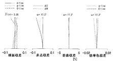
図1は本発明の実施例1のズームレンズの広角端(短焦点距離端)におけるレンズ断面図、図2、図3、図4はそれぞれ実施例1のズームレンズの広角端、中間のズーム位置、望遠端(長焦点距離端)における収差図である。
1 is a lens cross-sectional view at the wide-angle end (short focal length end) of the zoom lens according to
実施例1は、ズーム比2.0、開口比2.80〜3.31程度のズームレンズである。
図5は本発明の実施例2のズームレンズの広角端におけるレンズ断面図、図6、図7、図8はそれぞれ実施例2のズームレンズの広角端、中間のズーム位置、望遠端における収差図である。 FIG. 5 is a lens cross-sectional view at the wide-angle end of the zoom lens according to Embodiment 2 of the present invention, and FIGS. 6, 7, and 8 are aberration diagrams at the wide-angle end, the intermediate zoom position, and the telephoto end, respectively. It is.
実施例2は、ズーム比2.0、開口比2.80〜3.36程度のズームレンズである。 The second embodiment is a zoom lens having a zoom ratio of 2.0 and an aperture ratio of about 2.80 to 3.36.
図9は本発明の実施例3のズームレンズの広角端におけるレンズ断面図、図10、図11、図12はそれぞれ実施例3のズームレンズの広角端、中間のズーム位置、望遠端における収差図である。
FIG. 9 is a lens cross-sectional view at the wide-angle end of the zoom lens according to
実施例3は、ズーム比2.0、開口比2.80〜3.34程度のズームレンズである。 The third embodiment is a zoom lens having a zoom ratio of 2.0 and an aperture ratio of about 2.80 to 3.34.
図13は本発明の実施例4のズームレンズの広角端におけるレンズ断面図、図14、図15、図16はそれぞれ実施例4のズームレンズの広角端、中間のズーム位置、望遠端における収差図である。 FIG. 13 is a lens cross-sectional view at the wide-angle end of the zoom lens according to Embodiment 4 of the present invention. FIGS. 14, 15, and 16 are aberration diagrams at the wide-angle end, intermediate zoom position, and telephoto end of the zoom lens according to Embodiment 4, respectively. It is.
実施例4は、ズーム比3.05、開口比2.83〜4.28程度のズームレンズである。 The fourth embodiment is a zoom lens having a zoom ratio of 3.05 and an aperture ratio of about 2.83 to 4.28.
図17は本発明の実施例5のズームレンズの広角端におけるレンズ断面図、図18、図19、図20はそれぞれ実施例5のズームレンズの広角端、中間のズーム位置、望遠端における収差図である。
17 is a lens cross-sectional view at the wide-angle end of the zoom lens according to
実施例5は、ズーム比2.8、開口比2.95〜3.36程度のズームレンズである。 The fifth exemplary embodiment is a zoom lens having a zoom ratio of 2.8 and an aperture ratio of about 2.95 to 3.36.
図21は本発明の実施例6のズームレンズの広角端におけるレンズ断面図、図22、図23、図24はそれぞれ実施例6のズームレンズの広角端、中間のズーム位置、望遠端における収差図である。 FIG. 21 is a lens cross-sectional view at the wide-angle end of the zoom lens according to Embodiment 6 of the present invention. FIGS. 22, 23, and 24 are aberration diagrams at the wide-angle end, the intermediate zoom position, and the telephoto end, respectively. It is.
実施例6は、ズーム比3.0、開口比2.80〜4.04程度のズームレンズである。 Example 6 is a zoom lens having a zoom ratio of 3.0 and an aperture ratio of about 2.80 to 4.04.
図25は本発明の実施例7のズームレンズの広角端におけるレンズ断面図、図26、図27、図28はそれぞれ実施例7のズームレンズの広角端、中間のズーム位置、望遠端における収差図である。 FIG. 25 is a lens cross-sectional view at the wide-angle end of the zoom lens according to Embodiment 7 of the present invention. FIGS. 26, 27, and 28 are aberration diagrams at the wide-angle end, intermediate zoom position, and telephoto end, respectively. It is.
実施例7は、ズーム比4.09、開口比2.92〜4.63程度のズームレンズである。 The seventh embodiment is a zoom lens having a zoom ratio of about 4.09 and an aperture ratio of about 2.92 to 4.63.
図29は本発明のズームレンズを備えるデジタルスチルカメラ(撮像装置)の要部概略図である。 FIG. 29 is a schematic diagram of a main part of a digital still camera (imaging device) including the zoom lens of the present invention.
各実施例のズームレンズは撮像装置に用いられる撮影レンズ系である。各実施例のズームレンズをビデオカメラやデジタルスチルカメラの撮影光学系として使用する際にはCCDやCMOSセンサ等の固体撮像素子(光電変換素子)の撮像面に被写体像を形成する。 The zoom lens of each embodiment is a photographic lens system used in an imaging apparatus. When the zoom lens of each embodiment is used as an imaging optical system for a video camera or a digital still camera, a subject image is formed on the imaging surface of a solid-state imaging device (photoelectric conversion device) such as a CCD or CMOS sensor.
各レンズ断面図において、左方が被写体(物体)側(前方)で、右方が像側(後方)である。レンズ断面図において、L1は負の屈折力(光学的パワー=焦点距離の逆数)の第1レンズ群、L2は正の屈折力の第2レンズ群、L3は正の屈折力の第3レンズ群である。 In each lens cross-sectional view, the left is the subject (object) side (front), and the right is the image side (rear). In the lens cross-sectional view, L1 is a first lens group having negative refractive power (optical power = reciprocal of focal length), L2 is a second lens group having positive refractive power, and L3 is a third lens group having positive refractive power. It is.
SPは開口絞りであり、第2レンズ群L2の物体側に位置している。IPは像面である。 SP is an aperture stop, which is located on the object side of the second lens unit L2. IP is the image plane.
収差図において、d,g,Cは各々d線,g線,C線である。 In the aberration diagrams, d, g, and C are d-line, g-line, and C-line, respectively.
ΔM、ΔSは各々メリディオナル像面、サジタル像面を表している。倍率色収差はg線とC線によって表している。FnoはFナンバー、ωは半画角である。 ΔM and ΔS represent a meridional image plane and a sagittal image plane, respectively. Lateral chromatic aberration is represented by the g-line and C-line. Fno is the F number, and ω is the half angle of view.
尚、各実施例において広角端と望遠端は変倍用のレンズ群(第2レンズ群L2と第3レンズ群L3)が機構上光軸上移動可能な範囲の両端に位置したときのズーム位置をいう。 In each of the embodiments, the zoom position when the wide-angle end and the telephoto end are located at both ends of the range in which the lens unit for zooming (the second lens unit L2 and the third lens unit L3) can move on the optical axis on the mechanism. Say.
各実施例のズームレンズは、第1レンズ群L1、第2レンズ群L2、第3レンズ群L3
が、ズーミングに際し第1レンズ群と第2レンズ群の間隔、および第2レンズ群と第3レンズ群の間隔が変化するように移動する。別の言い方をすれば、ズーミングに際して、第1レンズ群と第2レンズ群、及び第2レンズ群と第3レンズ群は互いに異なる軌跡で移動している。第1レンズ群と第3レンズ群も互いに異なる軌跡で移動していることが望ましい。
The zoom lens of each embodiment includes a first lens unit L1, a second lens unit L2, and a third lens unit L3.
However, during zooming, the distance between the first lens group and the second lens group and the distance between the second lens group and the third lens group are changed. In other words, during zooming, the first lens group and the second lens group, and the second lens group and the third lens group move along different paths. It is desirable that the first lens group and the third lens group also move along different paths.
第2レンズ群L2は、光軸から垂直方向にかけて材料の屈折率が変化する屈折率分布を有する1枚の屈折率分布型レンズから構成されている。 The second lens unit L2 includes one refractive index distribution type lens having a refractive index distribution in which the refractive index of the material changes from the optical axis to the vertical direction.
このとき、光軸から垂直方向の距離hにおける波長λでの屈折率Nλ(h)は、波長λにおけるh0乗、h2乗、h4乗・・・係数をN00λ、N10λ、N20λ…として、次のように表されるものとしている。
At this time, the refractive index Nλ (h) at the wavelength λ at a distance h in the vertical direction from the optical axis is expressed as follows: h0, h2, h4,... It is supposed to be expressed as follows.
Nλ(h)=N00λ+N10λ*h2+N20λ*h4+… (a)
(a)式の係数N00λに相当するd,g,C線に対する値を順にN00d,N00g,N00Cとする。また、(a)式の係数N10λに相当するd,g,C線に対する値を順にN10d,N10g,N10Cとする。このとき、屈折率分布型レンズにおいてアッベ数と等価なアッベ数V00g,V10gは次のように表される。
Nλ (h) = N00λ + N10λ * h 2 + N20λ * h 4 + (a)
The values for the d, g, and C lines corresponding to the coefficient N00λ in the equation (a) are sequentially designated as N00d, N00g, and N00C. Further, values for the d, g, and C lines corresponding to the coefficient N10λ in the equation (a) are sequentially set as N10d, N10g, and N10C. At this time, Abbe numbers V00g and V10g equivalent to the Abbe numbers in the gradient index lens are expressed as follows.
V00g = (N00d−1)/(N00g−N00C)
V10g = N10d/(N10g−N10C)
基準光線をd線として、ラジアル型屈折率分布レンズを材料が屈折率N00dの薄肉均質レンズと考えた場合の屈折力(面の屈折力)をφsとする。また、屈折率分布媒質の持つ屈折力(媒質の屈折力)をφm=−2*N10d*t(tはレンズ厚)とする。このとき、ラジアル型屈折率分布レンズのペッツバール項PTZと近軸軸上色収差PACは、薄肉近似の下で次のように表せる。
V00g = (N00d-1) / (N00g-N00C)
V10g = N10d / (N10g-N10C)
The reference ray is d-line, and the refractive power (refractive power of the surface) when the radial type gradient index lens is considered as a thin homogeneous lens having a refractive index of N00d is φs. Further, the refractive power (refractive power of the medium) of the refractive index distribution medium is φm = −2 * N10d * t (t is the lens thickness). At this time, the Petzval term PTZ and the paraxial axial chromatic aberration PAC of the radial type gradient index lens can be expressed as follows under the thin-wall approximation.
PTZ = φs/N00d + φm/N002
PAC ∝ (φs/V00g + φm/V10g)
また、ラジアル型屈折率分布レンズの全体の屈折力は次のように表される。
PTZ = φs / N00d + φm / N00 2
PAC ∝ (φs / V00g + φm / V10g)
The overall refractive power of the radial type gradient index lens is expressed as follows.
Φ = φs + φm
上式を見て解るように、ラジアル型屈折率分布レンズのペッツバール項PTZ、近軸軸上色収差PACは、面で生じる項と媒質で生じる項の和となっており、
面と媒質の項でそれぞれ分母が異なる。ゆえに、各実施例では屈折率分布型のレンズ全体として等しい屈折力を持つ場合であっても、面の屈折力と媒質の屈折力の比率を変えることにより、レンズのペッツバール項、近軸軸上色収差がコントロールできる。
Φ = φs + φm
As can be seen from the above equation, the Petzval term PTZ and the paraxial axial chromatic aberration PAC of the radial type gradient index lens are the sum of the term generated on the surface and the term generated on the medium,
The denominator is different in terms of the surface and medium. Therefore, in each embodiment, even when the refractive index distribution type lens as a whole has the same refractive power, by changing the ratio between the refractive power of the surface and the refractive power of the medium, the Petzval term of the lens, on the paraxial axis Chromatic aberration can be controlled.
例えば正の屈折力を持つラジアル型屈折率分布レンズの場合、媒質もつ屈折力の比率を大きくするとペッツバール項が均質レンズの場合よりも小さくできる。また、屈折率分布の2次の項N10を波長毎に制御することで、色収差をコントロールできる。 For example, in the case of a radial type gradient index lens having a positive refractive power, the Petzval term can be made smaller than in the case of a homogeneous lens by increasing the ratio of the refractive power of the medium. Further, chromatic aberration can be controlled by controlling the second-order term N10 of the refractive index distribution for each wavelength.
本実施例では、N10を波長毎に制御することで、ペッツバール和、色収差をコントロールしている。 In this embodiment, Petzval sum and chromatic aberration are controlled by controlling N10 for each wavelength.
(a)式の係数N00λに相当するd線に対する値をN00dとする。屈折率分布型レンズを材料の屈折率がN00dの薄肉均質レンズであるとしたときの屈折力をφ2sとす
る。また、第2レンズ群L2の屈折率をΦ2とする。このとき各実施例において
−1.85<φ2s/Φ2 < 1 ‥‥‥(1)
なる条件を満足している。
A value for the d-line corresponding to the coefficient N00λ in the equation (a) is N00d. The refractive power when the refractive index distribution type lens is a thin homogeneous lens having a refractive index of N00d as a material is φ2s. Further, the refractive index of the second lens unit L2 is Φ2. At this time, in each example, −1.85 <φ2s / Φ2 <1 (1)
Is satisfied.
ここで薄肉均質レンズの屈折力φとは物体側と像側の面の曲率半径を各々r1、r2、材料の屈折率をnとするとき
φ=(n−1)*((1/r1)−(1/r2))
で表されるものである。
Here, the refractive power φ of the thin-walled homogeneous lens means that the radiuses of curvature of the object-side and image-side surfaces are r1 and r2, and the refractive index of the material is n, φ = (n−1) * ((1 / r1) -(1 / r2))
It is represented by
条件式(1)は、ラジアル型屈折率分布レンズのペッツバール項を制限するための条件式である。上限を超えるとラジアル型屈折率分布レンズのペッツバール項が、均質レンズを用いた場合よりも大きな値を持つため好ましくない。 Conditional expression (1) is a conditional expression for limiting the Petzval term of the radial type gradient index lens. Exceeding the upper limit is not preferable because the Petzval term of the radial type gradient index lens has a larger value than when a homogeneous lens is used.
また、下限を超えると、ラジアル型屈折率分布レンズの面で与えられる負の屈折力がより大きくなる。このときペッツバール項は均質レンズの場合より小さくできるものの、レンズ全体として正の屈折力をたせるため、屈折率分布媒質で与える正の屈折力を大きくしなければならない。屈折率分布媒質の屈折力を大きくするためには、光軸とレンズ周辺での屈折率差(屈折率分布の大きさ)を大きくするか、レンズ厚を厚くする必要がある。 If the lower limit is exceeded, the negative refractive power given by the surface of the radial type gradient index lens becomes larger. At this time, although the Petzval term can be made smaller than in the case of a homogeneous lens, in order to give a positive refractive power as a whole lens, the positive refractive power given by the refractive index distribution medium must be increased. In order to increase the refractive power of the refractive index distribution medium, it is necessary to increase the refractive index difference between the optical axis and the periphery of the lens (the size of the refractive index distribution) or to increase the lens thickness.
つまり、下限を超えるとラジアル型屈折率分布レンズの屈折率分布の大きさが大きくなる、若しくは屈折率分布型レンズのコンパクト化に不利となるため好ましくない。 That is, if the lower limit is exceeded, the size of the refractive index distribution of the radial type gradient index lens becomes large, or it is disadvantageous for making the gradient index lens compact, which is not preferable.
第2レンズ群L2が有するラジアル型屈折率分布レンズは、条件式(1)を満たすようにするのが良い。これによれば、屈折率分布が大きくなり過ぎたり、屈折率分布型レンズのコンパクト化を損なったりすること無く、第2レンズ群L2のもつペッツバール項を小さくすることができる。このとき、負の屈折力を持つ第1レンズ群L1と正の屈折力を持つ第3レンズ群L3の間でペッツバール項をバランスすると、光学系全体のペッツバール和を小さくすることができる。 The radial type gradient index lens included in the second lens unit L2 may satisfy the conditional expression (1). According to this, the Petzval term of the second lens unit L2 can be reduced without excessively increasing the refractive index distribution or impairing the compactness of the gradient index lens. At this time, if the Petzval term is balanced between the first lens unit L1 having negative refractive power and the third lens unit L3 having positive refractive power, the Petzval sum of the entire optical system can be reduced.
条件式(1)は以下の範囲とすることで、より第2レンズ群L2のペッツバール項を小さくすることができる。 By setting conditional expression (1) within the following range, the Petzval term of the second lens unit L2 can be further reduced.
−1.85 < φ2s/Φ2 < 0.5 ・・・(1a)
条件式(1a)は、さらに好ましくは以下の範囲とするのが良い。
-1.85 <φ2s / Φ2 <0.5 (1a)
Conditional expression (1a) is more preferably in the following range.
−1.85 < φ2s/Φ2 < 0 ・・・(1b)
屈折率分布型レンズを材料の屈折率がN00dの薄肉均質レンズであるとしたときの屈折力をφ2s、屈折率分布媒質によって生ずる屈折力をφ2mとする。このとき、各実施例において
−1.5<(φ2s/V00g+φ2m/V10g)/(Φ2/V00g)<1
‥‥‥(2)
なる条件を満足している。
-1.85 <φ2s / Φ2 <0 (1b)
When the gradient index lens is a thin homogeneous lens having a refractive index of N00d, the refractive power is φ2s, and the refractive power generated by the refractive index distribution medium is φ2m. At this time, in each example, −1.5 <(φ2s / V00g + φ2m / V10g) / (Φ2 / V00g) <1
(2)
Is satisfied.
条件式(2)は、ラジアル型屈折率分布レンズで生ずる色収差を制限するための条件式である。条件式(2)の上限又は下限の範囲を超えると、ラジアル型屈折率分布レンズで生じる色収差が大きくなり、光学系全体での色消しが困難となるため好ましくない。 Conditional expression (2) is a conditional expression for limiting the chromatic aberration generated in the radial type gradient index lens. Exceeding the upper limit or lower limit of conditional expression (2) is not preferable because chromatic aberration generated in the radial type gradient index lens becomes large and it becomes difficult to erase the entire optical system.
ここで、条件式(2)が正値を持つ場合は正の屈折力を持つ均質レンズと同じ方向に色収差が発生する。これに対して、負値を持つ場合、ラジアル型屈折率分布レンズは正の屈折力を持つにも関わらず通常の均質レンズと逆方向の色収差が生じる。 Here, when the conditional expression (2) has a positive value, chromatic aberration occurs in the same direction as the homogeneous lens having a positive refractive power. On the other hand, when it has a negative value, the radial type gradient index lens has positive refracting power, but causes chromatic aberration in the opposite direction to that of a normal homogeneous lens.
ゆえに、条件式(2)が負値を持つようなラジアル型屈折率分布レンズは均質レンズと異なった特性を示し、収差補正上有利となりうる。 Therefore, a radial type gradient index lens in which conditional expression (2) has a negative value exhibits characteristics different from those of a homogeneous lens, and can be advantageous in correcting aberrations.
第2レンズ群L2中の屈折率分布型レンズの中心厚をt2、ズームレンズの広角端における焦点距離をfwとする。このとき、各実施例において
0.1 < t2/fw < 1 ‥‥‥(3)
なる条件を満足している。
The center thickness of the gradient index lens in the second lens unit L2 is t2, and the focal length at the wide angle end of the zoom lens is fw. At this time, in each example, 0.1 <t2 / fw <1 (3)
Is satisfied.
ラジアル型屈折率分布媒質で生ずる屈折力はレンズ厚に比例する。このため、レンズ厚が条件式(3)の下限を超えると、収差補正に必要な媒質の屈折力を得るための屈折率分布が大きくなり過ぎるため好ましくない。また、上限を超えると屈折率分布の大きさは小さくできるが、第2レンズ群L2の全長が均質レンズを複数枚用いた場合と変わらなくなり、ラジアル型屈折率分布レンズを用いて第2レンズ群L2の構成レンズ枚数を削減し全系のコンパクト化を図った効果が相殺されてしまう。 The refractive power generated in the radial type gradient index medium is proportional to the lens thickness. For this reason, if the lens thickness exceeds the lower limit of conditional expression (3), the refractive index distribution for obtaining the refractive power of the medium necessary for aberration correction becomes too large, which is not preferable. If the upper limit is exceeded, the size of the refractive index distribution can be reduced. However, the total length of the second lens unit L2 is the same as that when a plurality of homogeneous lenses are used, and the second lens unit using a radial type refractive index distribution lens is used. The effect of reducing the number of lenses constituting L2 and making the entire system compact is offset.
沈胴時のコンパクト化の観点から、条件式(3)は以下の範囲とすることがより好ましい。 From the viewpoint of downsizing at the time of collapse, conditional expression (3) is more preferably set to the following range.
0.1 < t2/fw < 0.7 ・・・(3a)
条件式(3a)は、さらに以下の範囲とすることがより好ましい。
0.1 <t2 / fw <0.7 (3a)
Conditional expression (3a) is more preferably set to the following range.
0.1 < t2/fw < 0.5 ・・・(3b)
各実施例において、屈折率分布型レンズは、少なくとも1面が非球面形状である。
0.1 <t2 / fw <0.5 (3b)
In each embodiment, the gradient index lens has at least one aspherical shape.
光軸からの高さhの位置での光軸方向の面の変位を、面頂点を基準としてxとする。非球面係数をB,C,D,Eとし、近軸曲率半径をr、円錐係数をkとする。このとき非球面形状は次のように表せる。 The displacement of the surface in the direction of the optical axis at the position of the height h from the optical axis is assumed to be x with reference to the surface vertex. The aspheric coefficients are B, C, D, and E, the paraxial radius of curvature is r, and the cone coefficient is k. At this time, the aspherical shape can be expressed as follows.
x=(h2/r)/[1+{1−(1+k)*(h/r)2}1/2]
+B*h4 + C*h6 + D*h8 + E*h10 ‥‥‥(b)
ここで、(a)式のラジアル型屈折率分布における4次以上の項(N20、N30…)は、近軸的には屈折力は持たずに、均質レンズにおける非球面と同等の効果を持つことが知られている。つまり、光軸からの高さhが高くなるに従い屈折力が弱くなるような非球面形状(B<0)と、ラジアル型屈折率分布レンズでN20>0となる屈折率分布は、等価なものと考えることができる。
x = (h 2 / r) / [1+ {1− (1 + k) * (h / r) 2 } 1/2 ]
+ B * h 4 + C * h 6 + D * h 8 + E * h 10 (b)
Here, the fourth-order or higher terms (N20, N30...) In the radial type refractive index distribution of the formula (a) do not have refractive power paraxially, but have the same effect as an aspherical surface in a homogeneous lens. It is known. That is, an aspherical shape (B <0) in which the refractive power becomes weaker as the height h from the optical axis becomes higher and a refractive index distribution in which N20> 0 with a radial type refractive index distribution lens are equivalent. Can be considered.
まず、単色収差について考える。 First, consider monochromatic aberration.
(b)式の非球面係数Bと(a)式の屈折率分布の4次の項N20が等価であるならば、ラジアル型屈折率分布レンズの面に非球面を用いることで、屈折率分布の4次の項N20と非球面形状Bを相互に置き換えることができる。ラジアル型屈折率分布レンズを球面のみで構成する場合、光学系の構成レンズ枚数を削減するため複雑な非球面効果を屈折率分布媒質のみで与えようとすると、屈折率分布の4次以上の高次項が肥大化する。このとき、ラジアル型屈折率分布レンズの動径方向(レンズ周辺方向)の屈折率分布に高次項の影響によるうねりが現れ好ましくない。そこで、各実施例ではラジアル型屈折率分布レンズに非球面を用いて屈折率分布の高次の項を非球面形状に可能な限り置き換えることによって、屈折率分布に無駄な分布がつくのを防いでいる。 If the aspheric coefficient B in the equation (b) and the fourth-order term N20 in the refractive index distribution in the equation (a) are equivalent, the refractive index distribution can be obtained by using an aspheric surface for the surface of the radial type refractive index distribution lens. The fourth-order term N20 and the aspherical surface shape B can be replaced with each other. When a radial type refractive index distribution lens is composed only of a spherical surface, if a complicated aspherical effect is to be given only by the refractive index distribution medium in order to reduce the number of lenses constituting the optical system, the refractive index distribution is higher than the fourth order. The next term is enlarged. At this time, undulation due to the influence of higher-order terms appears in the refractive index distribution in the radial direction (lens peripheral direction) of the radial type refractive index distribution lens. Therefore, in each embodiment, an aspherical surface is used for the radial type refractive index distribution lens, and a higher-order term of the refractive index distribution is replaced with an aspherical shape as much as possible to prevent the refractive index distribution from being wasted. It is out.
次に、色収差について考える。
均質レンズにおいて、非球面形状の面を用いて色収差を補正することは困難である。一方、ラジアル型屈折率分布レンズの場合、屈折率分布の4次以上の高次項を波長毎にコントロールすることで、波長毎に異なる非球面効果を与えることが可能となる。
Next, chromatic aberration will be considered.
In a homogeneous lens, it is difficult to correct chromatic aberration using an aspherical surface. On the other hand, in the case of a radial type refractive index distribution lens, it is possible to give different aspherical effects for each wavelength by controlling the higher order terms of the fourth or higher order of the refractive index distribution for each wavelength.
各実施例では、屈折率分布の4次の項N20を波長毎にコントロールし、球面収差やコマ収差を各波長で補正している。
また各実施例では、単色収差はできるだけ非球面形状の面で補正し、色収差は屈折率分布を制御することによって補正するように、ラジアル型屈折率分布レンズを用いている。
In each embodiment, the fourth-order term N20 of the refractive index distribution is controlled for each wavelength, and spherical aberration and coma aberration are corrected at each wavelength.
In each embodiment, a radial type refractive index distribution lens is used so that the monochromatic aberration is corrected by an aspherical surface as much as possible, and the chromatic aberration is corrected by controlling the refractive index distribution.
尚、各実施例において諸収差のうち歪曲収差は、公知の電気的な収差補正方法を用いて補正してもよい。 In each embodiment, distortion among the various aberrations may be corrected using a known electrical aberration correction method.
各実施例は以上の様に各要素を設定する事により、特に、固体撮像素子を用いた撮影系に好適なズームレンズを得ている。 In each embodiment, a zoom lens suitable for an imaging system using a solid-state image sensor is obtained by setting each element as described above.
特に構成レンズ枚数が少なくコンパクトで、沈胴式のズームレンズに適した、ズーム比が2〜4倍程度の高い光学性能を有するズームレンズを達成している。 In particular, a zoom lens having a small number of constituent lenses, a compact and suitable for a retractable zoom lens and having a high optical performance with a zoom ratio of about 2 to 4 times has been achieved.
次に各実施例の特徴について説明する。 Next, features of each embodiment will be described.
各実施例のズーム方式は、次のとおりである。 The zoom method of each embodiment is as follows.
実施例1〜3、実施例5のズームレンズは、物体側から像側へ順に、負の屈折力の第1レンズ群L1、正の屈折力の第2レンズ群L2、正の屈折力の第3レンズ群L3で構成されている。広角端から望遠端へのズーミングに際して、第1レンズ群L1が像側へ移動し、第2、第3レンズ群L2、L3が物体側に互いに異なった軌跡で移動している。第2、第3レンズ群L2、L3の移動により主な変倍を行い、第1レンズ群L1の移動により変倍に伴う像点の移動を補償している。 In the zoom lenses of Examples 1 to 3 and Example 5, in order from the object side to the image side, the first lens unit L1 having a negative refractive power, the second lens unit L2 having a positive refractive power, and the first lens unit having a positive refractive power. It consists of three lens units L3. During zooming from the wide-angle end to the telephoto end, the first lens unit L1 moves to the image side, and the second and third lens units L2 and L3 move to the object side along different tracks. The main zooming is performed by the movement of the second and third lens units L2 and L3, and the movement of the image point accompanying the zooming is compensated for by the movement of the first lens unit L1.
実施例4、実施例6〜7のズームレンズは、物体側から像側へ順に、負の屈折力の第1レンズ群L1、正の屈折力の第2レンズ群L2、正の屈折力の第3レンズ群L3で構成されている。広角端から望遠端へのズーミングに際して、第1レンズ群L1が像側に凸状の往復移動し、第2、第3レンズ群L2、L3が物体側に互いに異なった軌跡で移動している。第2、第3レンズ群L2、L3の移動により主な変倍を行い、第1レンズ群L1の移動により変倍に伴う像点の移動を補償している。 In the zoom lenses of Example 4 and Examples 6 to 7, in order from the object side to the image side, the first lens unit L1 having a negative refractive power, the second lens unit L2 having a positive refractive power, and the first lens unit having a positive refractive power. It consists of three lens units L3. During zooming from the wide-angle end to the telephoto end, the first lens unit L1 reciprocates convexly toward the image side, and the second and third lens units L2 and L3 move along different paths toward the object side. The main zooming is performed by the movement of the second and third lens units L2 and L3, and the movement of the image point accompanying the zooming is compensated for by the movement of the first lens unit L1.
次に各実施例のレンズ構成について説明する。 Next, the lens configuration of each example will be described.
尚、レンズ形状における凸形状、凹形状、正メニスカス形状、負メニスカス形状等は光軸近傍における形状である。 The convex shape, concave shape, positive meniscus shape, negative meniscus shape, etc. in the lens shape are shapes in the vicinity of the optical axis.
実施例1は、負の屈折力の第1レンズ群L1を物体側が凸面で負メニスカス形状の均質材料より成る均質レンズと物体側が凸面で正メニスカス形状の均質レンズで構成している。また、正の屈折力の第2レンズ群L2を物体側が凸面の負メニスカス形状で、光軸(レンズ中心)から垂直方向(レンズ周辺)に向かうほど材料の屈折率が小さくなる分布のラジアル型屈折率分布レンズ1枚で構成している。 In Example 1, the first lens unit L1 having negative refractive power is configured by a homogeneous lens made of a homogeneous material having a negative meniscus shape with a convex surface on the object side and a homogeneous lens having a positive meniscus shape with a convex surface on the object side. Further, the second lens unit L2 having a positive refractive power has a negative meniscus shape with a convex surface on the object side, and radial refraction having a distribution in which the refractive index of the material decreases from the optical axis (lens center) toward the vertical direction (lens periphery). It consists of a single rate distribution lens.
また、正の屈折力の第3レンズ群L3を像側が凸面で正メニスカス形状の1枚の均質レンズで構成している。 In addition, the third lens unit L3 having a positive refractive power is composed of one homogeneous lens having a convex surface on the image side and a positive meniscus shape.
また実施例1は、第1レンズ群L1の物体側から数えた1枚目(以下「1枚目」という)のレンズの像側の面、第2レンズ群L2の物体側の面、第3レンズ群L3の像側の面をそれぞれ非球面形状としている。 In Example 1, the image side surface of the first lens (hereinafter referred to as “first lens”) counted from the object side of the first lens unit L1, the object side surface of the second lens unit L2, the third Each of the image side surfaces of the lens unit L3 has an aspherical shape.
実施例2は、負の屈折力の第1レンズ群L1を物体側が凸面で負メニスカス形状の均質レンズと物体側が凸面で正メニスカス形状の均質レンズで構成している。また、正の屈折力の第2レンズ群L2を物体側が凸面の正メニスカス形状で、光軸から垂直方向に向かうほど屈折率が小さくなる分布のラジアル型屈折率分布レンズ1枚で構成している。また、正の屈折力の第3レンズ群L3を像側が凸面で正メニスカス形状の1枚の均質レンズで構成している。 In Example 2, the first lens unit L1 having negative refractive power is configured by a negative meniscus homogeneous lens having a convex surface on the object side and a positive meniscus homogeneous lens having a convex surface on the object side. In addition, the second lens unit L2 having a positive refractive power is configured by a single radial type refractive index distribution lens having a positive meniscus shape having a convex surface on the object side and a refractive index that decreases in the vertical direction from the optical axis. . In addition, the third lens unit L3 having a positive refractive power is composed of one homogeneous lens having a convex surface on the image side and a positive meniscus shape.
また実施例2は、第1レンズ群L11枚目レンズの像側の面、第2レンズ群L2の物体側の面、第3レンズ群L3の像側の面をそれぞれ非球面形状としている。 In Example 2, the image-side surface of the first lens unit L11th lens, the object-side surface of the second lens unit L2, and the image-side surface of the third lens unit L3 are aspherical.
実施例3は、負の屈折力の第1レンズ群L1を物体側が凸面で負メニスカス形状の均質レンズと物体側が凸面で正メニスカス形状の均質レンズで構成している。また、正の屈折力の第2レンズ群L2を物体側が凸面の正メニスカス形状で、光軸から垂直方向に向かうほど屈折率が小さくなる分布のラジアル型屈折率分布レンズ1枚で構成している。また、正の屈折力の第3レンズ群L3を両凸形状の1枚の均質レンズで構成している。 In Example 3, the first lens unit L1 having negative refractive power is configured by a negative meniscus homogeneous lens having a convex surface on the object side and a positive meniscus homogeneous lens having a convex surface on the object side. In addition, the second lens unit L2 having a positive refractive power is configured by a single radial type refractive index distribution lens having a positive meniscus shape having a convex surface on the object side and a refractive index that decreases in the vertical direction from the optical axis. . The third lens unit L3 having a positive refractive power is composed of a single biconvex homogeneous lens.
また実施例3は、第1レンズ群L1の1枚目レンズの像側の面、第2レンズ群L2の物体側の面、第3レンズ群L3の像側の面をそれぞれ非球面形状としている。 In Example 3, the image-side surface of the first lens in the first lens unit L1, the object-side surface of the second lens unit L2, and the image-side surface of the third lens unit L3 are aspherical. .
実施例4は、負の屈折力の第1レンズ群L1を物体側が平面の平凹形状の均質レンズと物体側が凸面で正メニスカス形状の均質レンズで構成している。また、正の屈折力の第2レンズ群L2を物体側が凸面の負メニスカス形状で、光軸から垂直方向に向かうほど屈折率が小さくなる分布のラジアル型屈折率分布レンズ1枚で構成している。また、正の屈折力の第3レンズ群L3を両凸形状で、光軸から垂直方向に向かうほど屈折率が大きくなる分布のラジアル型屈折率分布レンズ1枚で構成している。 In Example 4, the first lens unit L1 having a negative refractive power is configured by a plano-concave homogeneous lens having a flat object side and a positive meniscus homogeneous lens having a convex surface on the object side. The second lens unit L2 having a positive refractive power is composed of a single radial type refractive index distribution lens having a negative meniscus shape with a convex surface on the object side and a refractive index that decreases in the vertical direction from the optical axis. . The third lens unit L3 having a positive refractive power has a biconvex shape and is composed of one radial type refractive index distribution lens having a distribution in which the refractive index increases in the vertical direction from the optical axis.
また実施例4は、第1レンズ群L1の1枚目レンズの像側の面、第2レンズ群L2の物体側の面、第3レンズ群L3の像側の面をそれぞれ非球面形状としている。 In Example 4, the image-side surface of the first lens in the first lens unit L1, the object-side surface of the second lens unit L2, and the image-side surface of the third lens unit L3 are aspherical. .
実施例5は、負の屈折力の第1レンズ群L1を両凹形状で、光軸から垂直方向に向かうほど屈折率が大きくなる分布のラジアル型屈折率分布レンズ1枚で構成している。また、正の屈折力の第2レンズ群L2を物体側が凸面の負メニスカス形状で、光軸から垂直方向に向かうほど屈折率が小さくなる分布のラジアル型屈折率分布レンズ1枚で構成している。また、正の屈折力の第3レンズ群L3を両凸形状の1枚の均質レンズで構成している。 In the fifth embodiment, the first lens unit L1 having negative refractive power has a biconcave shape, and includes one radial type refractive index distribution lens having a distribution in which the refractive index increases in the vertical direction from the optical axis. The second lens unit L2 having a positive refractive power is composed of a single radial type refractive index distribution lens having a negative meniscus shape with a convex surface on the object side and a refractive index that decreases in the vertical direction from the optical axis. . The third lens unit L3 having a positive refractive power is composed of a single biconvex homogeneous lens.
また実施例5は、第1レンズ群L1の像側の面、第2レンズ群L2の物体側の面、第3レンズ群L3の像側の面をそれぞれ非球面形状としている。 In Example 5, the image-side surface of the first lens unit L1, the object-side surface of the second lens unit L2, and the image-side surface of the third lens unit L3 are aspherical.
実施例6は、負の屈折力の第1レンズ群L1を両凹形状で、光軸から垂直方向に向かうほど屈折率が大きくなる分布のラジアル型屈折率分布レンズ1枚で構成している。また、正の屈折力の第2レンズ群L2を物体側が凸面の負メニスカス形状で、光軸から垂直方向に向かうほど屈折率が小さくなる分布のラジアル型屈折率分布レンズ1枚で構成している。また、正の屈折力の第3レンズ群L3を像側が凸面の正メニスカス形状で、光軸から垂直方向に向かうほど屈折率が大きくなる分布のラジアル型屈折率分布レンズ1枚で構成している。 In the sixth embodiment, the first lens unit L1 having negative refractive power has a biconcave shape, and includes one radial type refractive index distribution lens having a distribution in which the refractive index increases in the vertical direction from the optical axis. The second lens unit L2 having a positive refractive power is composed of a single radial type refractive index distribution lens having a negative meniscus shape with a convex surface on the object side and a refractive index that decreases in the vertical direction from the optical axis. . The third lens unit L3 having a positive refractive power has a positive meniscus shape with a convex surface on the image side, and is composed of one radial type refractive index distribution lens having a distribution in which the refractive index increases in the vertical direction from the optical axis. .
また実施例6は、第1〜第3レンズ群L1〜L3の全ての面を非球面形状としている。 In Example 6, all surfaces of the first to third lens units L1 to L3 are aspherical.
実施例7は、負の屈折力の第1レンズ群L1を両凹形状で、光軸から垂直方向に向かうほど屈折率が大きくなる分布のラジアル型屈折率分布レンズ1枚で構成している。また、正の屈折力の第2レンズ群L2を物体側が凸面の負メニスカス形状で、光軸から垂直方向に向かうほど屈折率が小さくなる分布のラジアル型屈折率分布レンズ1枚で構成している。また、正の屈折力の第3レンズ群L3を像側が凸面の正メニスカス形状で、光軸から垂直方向に向かうほど屈折率が大きくなる分布のラジアル型屈折率分布レンズ1枚で構成している。 In the seventh embodiment, the first lens unit L1 having negative refractive power has a biconcave shape, and includes one radial type refractive index distribution lens having a distribution in which the refractive index increases in the vertical direction from the optical axis. The second lens unit L2 having a positive refractive power is composed of a single radial type refractive index distribution lens having a negative meniscus shape with a convex surface on the object side and a refractive index that decreases in the vertical direction from the optical axis. . The third lens unit L3 having a positive refractive power has a positive meniscus shape with a convex surface on the image side, and is composed of one radial type refractive index distribution lens having a distribution in which the refractive index increases in the vertical direction from the optical axis. .
また実施例7は、第1〜第3レンズ群L1〜L3の全ての面を非球面形状としている。 In Example 7, all the surfaces of the first to third lens units L1 to L3 are aspherical.
次に、本発明の実施例1〜7に対応する数値実施例1〜7を示す。 Next, numerical examples 1 to 7 corresponding to the first to seventh embodiments of the present invention will be described.
数値実施例において、iは物体側からの面の順序を示す。riは第i番目のレンズ面(面)の曲率半径、diは第i面と第(i+1)面との間のレンズ肉厚および空気間隔、Ni、νiはそれぞれ第i番目の部材のd線に対する屈折率、アッベ数を示す。 In the numerical examples, i indicates the order of the surfaces from the object side. ri is the radius of curvature of the i-th lens surface (surface), di is the lens thickness and air spacing between the i-th surface and the (i + 1) -th surface, and Ni and νi are d-lines of the i-th member, respectively. Indicates the refractive index and Abbe number.
また、kは円錐係数、B,C,D,Eは各々非球面係数である。非球面形状は光軸からの高さhの位置での光軸方向の変位を面頂点を基準にしてxとするとき
x=(h2/r)/[1+{1−(1+k)*(h/r)2}1/2]
+B*h4 + C*h6 + D*h8 + E*h10
で表される。但しrは近軸曲率半径である。
K is a conical coefficient, and B, C, D, and E are aspherical coefficients. The aspherical shape is defined as x = (h 2 / r) / [1+ {1− (1 + k) * (), where x is the displacement in the optical axis direction at a height h from the optical axis with respect to the surface vertex. h / r) 2 } 1/2 ]
+ B * h 4 + C * h 6 + D * h 8 + E * h 10
It is represented by Where r is the paraxial radius of curvature.
又「e−0x」は「×10−x」を意味している。fは焦点距離、FnoはFナンバー、ωは半画角を示す。 “E-0x” means “× 10-x”. f represents a focal length, Fno represents an F number, and ω represents a half angle of view.
ラジアル型の屈折率分布表現式は、レンズの動径方向距離(光軸からの高さ)をhとし、係数をN00,N10,N20としたとき、高さhでの屈折率N(h)を
N(h)=N00+N10*h2 + N20*h4
として表している。
In the radial type refractive index distribution expression, when the radial distance (height from the optical axis) of the lens is h and the coefficients are N00, N10, N20, the refractive index N (h) at the height h. N (h) = N00 + N10 * h 2 + N20 * h 4
It represents as.
各数値実施例では各係数N00,N10,N20をC,d,g線に対して各々示している。 In each numerical example, the coefficients N00, N10, and N20 are shown for the C, d, and g lines, respectively.
GRINは屈折率分布型の材料であることを示している。 GRIN indicates a refractive index distribution type material.
又、前述の各条件式と各実施例との関係を表−1、表−2に示す。 Tables 1 and 2 show the relationship between the above-described conditional expressions and each example.

次に本発明のズームレンズを撮影光学系として用いたデジタルカメラ(光学機器)の実施例を図29を用いて説明する。 Next, an embodiment of a digital camera (optical apparatus) using the zoom lens of the present invention as a photographing optical system will be described with reference to FIG.
図29において、20はデジタルカメラ本体、21は上述の実施例1〜7のズームレンズによって構成された撮影光学系である。22は撮影光学系21によって被写体像を受光するCCD等の撮像素子である。23は撮像素子22が受光した被写体像を記録する記録手段、24は不図示の表示素子に表示された被写体像を観察するためのファインダーである。
In FIG. 29,
上記表示素子は液晶パネル等によって構成され、撮像素子22上に形成された被写体像が表示される。
The display element is constituted by a liquid crystal panel or the like, and a subject image formed on the
このように本発明のズームレンズをデジタルカメラ等の光学機器に適用することにより、小型で高い光学性能を有する撮像装置を実現している。 In this way, by applying the zoom lens of the present invention to an optical device such as a digital camera, a small-sized imaging device having high optical performance is realized.
L1 第1レンズ群
L2 第2レンズ群
L3 第3レンズ群
SP Fナンバー決定部材(開口絞り)
IP 像面
d d線
g g線
ΔS サジタル像面
ΔM メリディオナル像面
L1 First lens group L2 Second lens group L3 Third lens group SP F-number determining member (aperture stop)
IP image plane dd line g g line ΔS sagittal image plane ΔM meridional image plane
Claims (7)
該第2レンズ群は、光軸に対し垂直な方向に材料の屈折率が変化する屈折率分布型レンズから構成され、
光軸から垂直な方向の距離hにおける波長λでの屈折率Nλ(h)は、波長λにおけるh0乗、h2乗、h4乗・・・の係数をN00λ、N10λ、N20λ…とするとき、
Nλ(h)=N00λ+N10λ*h 2 +N20λ*h 4 +…
で表されるものであり、該係数N00λに相当するd線に対する値をN00dとし、該屈折率分布型レンズは、材料の屈折率がN00dの薄肉均質レンズであるとしたときの屈折力をφ2s、該第2レンズ群の屈折力をΦ2とするとき
−1.85<φ2s/Φ2 < 1
なる条件を満足することを特徴とするズームレンズ。 In order from the object side to the image side, a first lens group having a negative refractive power, a second lens group having a positive refractive power, and a third lens group having a positive refractive power are arranged. In a zoom lens that changes an interval between the second lens group and an interval between the second lens group and the third lens group,
Second lens group, the refractive index of the wood charge in a direction perpendicular to the optical axis is composed of refraction index distribution type lens you change,
The refractive index Nλ (h) at the wavelength λ at a distance h in the direction perpendicular to the optical axis is expressed by the following factors: N00λ, N10λ, N20λ,.
Nλ (h) = N00λ + N10λ * h 2 + N20λ * h 4 +
The value for the d-line corresponding to the coefficient N00λ is N00d, and the gradient index lens has a refractive power of φ2 s when it is a thin homogeneous lens having a refractive index of N00d. When the refractive power of the second lens group is Φ2, −1.85 <φ2s / Φ2 <1
A zoom lens characterized by satisfying the following conditions:
−1.85<φ2s/Φ2≦0.750-1.85 <φ2s / Φ2 ≦ 0.750
なる条件を満足することを特徴とする請求項1に記載のズームレンズ。The zoom lens according to claim 1, wherein the following condition is satisfied.
−1.85<φ2s/Φ2 < 0.5-1.85 <φ2s / Φ2 <0.5
なる条件を満足することを特徴とする請求項1に記載のズームレンズ。The zoom lens according to claim 1, wherein the following condition is satisfied.
該係数N10λに相当するd,g,C線に対する値を順にN10d,N10g,N10Cとし、
これらの値に対する屈折率分布型レンズの材料のアッベ数V00g,V10gを
V00g = (N00d−1)/(N00g−N00C)
V10g = N10d/(N10g−N10C)
とし、該屈折率分布型レンズを材料の屈折率がN00dの薄肉均質レンズであるとしたときの屈折力をφ2s、屈折率分布媒質によって生ずる屈折力をφ2mとするとき
−1.5<(φ2s/V00g+φ2m/V10g)/(Φ2/V00g)<1
なる条件を満足することを特徴とする、請求項1乃至3のいずれか1項に記載のズームレンズ。 In the gradient index lens, values for the d, g, and C lines corresponding to the coefficient N00λ are sequentially set to N00d, N00g, N00C,
The values for the d, g, and C lines corresponding to the coefficient N10λ are N10d, N10g, and N10C in order,
The Abbe numbers V00g and V10g of the gradient index lens material for these values are V00g = (N00d-1) / (N00g-N00C)
V10g = N10d / (N10g-N10C)
When the refractive index distribution type lens is a thin homogeneous lens having a refractive index of N00d as a material, the refractive power is φ2s, and the refractive power generated by the refractive index distribution medium is φ2m. −1.5 <(φ2s / V00g + φ2m / V10g) / (Φ2 / V00g) <1
And satisfies the following condition, the zoom lens according to any one of claims 1 to 3.
0.1 < t2/fw < 1
なる条件を満足することを特徴とする請求項1乃至4のいずれか1項に記載のズームレンズ。 When the center thickness of the gradient index lens is t2, and the focal length at the wide angle end of the zoom lens is fw,
0.1 <t2 / fw <1
The zoom lens according to any one of claims 1 to 4, characterized by satisfying the following condition.
And any one of the zoom lens according to claim 1 to 6, the imaging apparatus being characterized in that a photoelectric conversion element for receiving an image formed by the zoom lens.
Priority Applications (1)
| Application Number | Priority Date | Filing Date | Title |
|---|---|---|---|
| JP2006243938A JP4956102B2 (en) | 2006-09-08 | 2006-09-08 | Zoom lens and imaging apparatus having the same |
Applications Claiming Priority (1)
| Application Number | Priority Date | Filing Date | Title |
|---|---|---|---|
| JP2006243938A JP4956102B2 (en) | 2006-09-08 | 2006-09-08 | Zoom lens and imaging apparatus having the same |
Publications (3)
| Publication Number | Publication Date |
|---|---|
| JP2008065124A JP2008065124A (en) | 2008-03-21 |
| JP2008065124A5 JP2008065124A5 (en) | 2009-10-22 |
| JP4956102B2 true JP4956102B2 (en) | 2012-06-20 |
Family
ID=39287884
Family Applications (1)
| Application Number | Title | Priority Date | Filing Date |
|---|---|---|---|
| JP2006243938A Expired - Fee Related JP4956102B2 (en) | 2006-09-08 | 2006-09-08 | Zoom lens and imaging apparatus having the same |
Country Status (1)
| Country | Link |
|---|---|
| JP (1) | JP4956102B2 (en) |
Families Citing this family (4)
| Publication number | Priority date | Publication date | Assignee | Title |
|---|---|---|---|---|
| KR20130013514A (en) | 2011-07-28 | 2013-02-06 | 삼성전자주식회사 | Zoom lens and photographing device having the same |
| JP5787676B2 (en) * | 2011-09-02 | 2015-09-30 | キヤノン株式会社 | Zoom lens and optical equipment |
| JP2013061548A (en) * | 2011-09-14 | 2013-04-04 | Canon Inc | Imaging optical system and optical instrument having refraction index distribution type lens |
| KR101725982B1 (en) | 2014-11-17 | 2017-05-15 | 주식회사 엠지비엔도스코피 | Imaging Lens System for Endoscope |
Family Cites Families (5)
| Publication number | Priority date | Publication date | Assignee | Title |
|---|---|---|---|---|
| JPS61231517A (en) * | 1985-04-05 | 1986-10-15 | Canon Inc | Variable focal length lens |
| JPH0668573B2 (en) * | 1985-06-10 | 1994-08-31 | キヤノン株式会社 | Variable focal length lens |
| JPH0256515A (en) * | 1988-08-23 | 1990-02-26 | Olympus Optical Co Ltd | Variable power lens |
| JPH103037A (en) * | 1996-06-14 | 1998-01-06 | Minolta Co Ltd | Zoom lens |
| JPH10333034A (en) * | 1997-06-03 | 1998-12-18 | Olympus Optical Co Ltd | Optical system |
-
2006
- 2006-09-08 JP JP2006243938A patent/JP4956102B2/en not_active Expired - Fee Related
Also Published As
| Publication number | Publication date |
|---|---|
| JP2008065124A (en) | 2008-03-21 |
Similar Documents
| Publication | Publication Date | Title |
|---|---|---|
| JP3709148B2 (en) | Zoom lens system | |
| JP6302397B2 (en) | Wide angle zoom lens | |
| JP4030743B2 (en) | Zoom lens system | |
| JP4794915B2 (en) | Zoom lens and imaging apparatus having the same | |
| US9477070B2 (en) | Zoom lens and imaging apparatus | |
| JP2009037125A (en) | Three-group zoom lens system and image pickup apparatus using the same | |
| JP2004333767A (en) | Zoom lens and optical equipment having the same | |
| JP2009092836A (en) | Two-group zoom lens, and imaging device equipped therewith | |
| JP4827454B2 (en) | Zoom lens and imaging apparatus having the same | |
| JP5522988B2 (en) | Zoom lens and imaging apparatus using the same | |
| JP2011145566A (en) | Zoom lens and optical apparatus having the same | |
| JP6000842B2 (en) | Imaging optics | |
| JP4444625B2 (en) | Zoom lens and imaging apparatus having the same | |
| JP4956102B2 (en) | Zoom lens and imaging apparatus having the same | |
| JP5854978B2 (en) | Zoom lens | |
| KR20130013513A (en) | Zoom lens and photographing device having the same | |
| JP7188276B2 (en) | Zoom lenses, imaging optical devices and digital devices | |
| JP2019008088A (en) | Zoom lens and imaging apparatus including the same | |
| JP4817551B2 (en) | Zoom lens | |
| JP6071473B2 (en) | Zoom lens and imaging apparatus using the same | |
| JP4838899B2 (en) | Zoom lens and optical apparatus using the same | |
| JP2010230895A (en) | Zoom lens | |
| JP2009251362A (en) | Three-group zoom lens and imaging apparatus equipped therewith | |
| JP4379957B2 (en) | Rear focus zoom lens and optical apparatus using the same | |
| JP2013054191A (en) | Zoom lens |
Legal Events
| Date | Code | Title | Description |
|---|---|---|---|
| A521 | Written amendment |
Free format text: JAPANESE INTERMEDIATE CODE: A523 Effective date: 20090903 |
|
| A621 | Written request for application examination |
Free format text: JAPANESE INTERMEDIATE CODE: A621 Effective date: 20090903 |
|
| A977 | Report on retrieval |
Free format text: JAPANESE INTERMEDIATE CODE: A971007 Effective date: 20111216 |
|
| A131 | Notification of reasons for refusal |
Free format text: JAPANESE INTERMEDIATE CODE: A131 Effective date: 20111220 |
|
| A521 | Written amendment |
Free format text: JAPANESE INTERMEDIATE CODE: A523 Effective date: 20120220 |
|
| TRDD | Decision of grant or rejection written | ||
| A01 | Written decision to grant a patent or to grant a registration (utility model) |
Free format text: JAPANESE INTERMEDIATE CODE: A01 Effective date: 20120313 |
|
| A01 | Written decision to grant a patent or to grant a registration (utility model) |
Free format text: JAPANESE INTERMEDIATE CODE: A01 |
|
| A61 | First payment of annual fees (during grant procedure) |
Free format text: JAPANESE INTERMEDIATE CODE: A61 Effective date: 20120316 |
|
| FPAY | Renewal fee payment (event date is renewal date of database) |
Free format text: PAYMENT UNTIL: 20150323 Year of fee payment: 3 |
|
| LAPS | Cancellation because of no payment of annual fees |