JP4954331B2 - Throw-away rotary tool - Google Patents
Throw-away rotary tool Download PDFInfo
- Publication number
- JP4954331B2 JP4954331B2 JP2010514171A JP2010514171A JP4954331B2 JP 4954331 B2 JP4954331 B2 JP 4954331B2 JP 2010514171 A JP2010514171 A JP 2010514171A JP 2010514171 A JP2010514171 A JP 2010514171A JP 4954331 B2 JP4954331 B2 JP 4954331B2
- Authority
- JP
- Japan
- Prior art keywords
- convex
- peripheral wall
- cutting head
- standing
- axis
- Prior art date
- Legal status (The legal status is an assumption and is not a legal conclusion. Google has not performed a legal analysis and makes no representation as to the accuracy of the status listed.)
- Active
Links
- 238000005520 cutting process Methods 0.000 claims description 118
- 230000002093 peripheral effect Effects 0.000 claims description 73
- 230000005484 gravity Effects 0.000 claims description 12
- 230000008878 coupling Effects 0.000 claims description 10
- 238000010168 coupling process Methods 0.000 claims description 10
- 238000005859 coupling reaction Methods 0.000 claims description 10
- 239000000463 material Substances 0.000 claims description 5
- 230000005540 biological transmission Effects 0.000 description 16
- 238000003754 machining Methods 0.000 description 10
- 238000012545 processing Methods 0.000 description 8
- 238000005553 drilling Methods 0.000 description 7
- 230000004323 axial length Effects 0.000 description 6
- 238000005452 bending Methods 0.000 description 6
- 230000000694 effects Effects 0.000 description 6
- 238000005259 measurement Methods 0.000 description 5
- 229910001315 Tool steel Inorganic materials 0.000 description 3
- 230000009471 action Effects 0.000 description 2
- 230000001154 acute effect Effects 0.000 description 2
- 230000007423 decrease Effects 0.000 description 2
- 238000007599 discharging Methods 0.000 description 2
- 229910045601 alloy Inorganic materials 0.000 description 1
- 239000000956 alloy Substances 0.000 description 1
- 239000011195 cermet Substances 0.000 description 1
- 238000006243 chemical reaction Methods 0.000 description 1
- 230000005489 elastic deformation Effects 0.000 description 1
- 238000004519 manufacturing process Methods 0.000 description 1
- 238000000034 method Methods 0.000 description 1
- 238000012986 modification Methods 0.000 description 1
- 230000004048 modification Effects 0.000 description 1
- 230000008569 process Effects 0.000 description 1
- 238000012360 testing method Methods 0.000 description 1
- 239000011882 ultra-fine particle Substances 0.000 description 1
Images

Classifications
-
- B—PERFORMING OPERATIONS; TRANSPORTING
- B23—MACHINE TOOLS; METAL-WORKING NOT OTHERWISE PROVIDED FOR
- B23B—TURNING; BORING
- B23B51/00—Tools for drilling machines
- B23B51/02—Twist drills
-
- B—PERFORMING OPERATIONS; TRANSPORTING
- B23—MACHINE TOOLS; METAL-WORKING NOT OTHERWISE PROVIDED FOR
- B23B—TURNING; BORING
- B23B2251/00—Details of tools for drilling machines
- B23B2251/02—Connections between shanks and removable cutting heads
-
- Y—GENERAL TAGGING OF NEW TECHNOLOGICAL DEVELOPMENTS; GENERAL TAGGING OF CROSS-SECTIONAL TECHNOLOGIES SPANNING OVER SEVERAL SECTIONS OF THE IPC; TECHNICAL SUBJECTS COVERED BY FORMER USPC CROSS-REFERENCE ART COLLECTIONS [XRACs] AND DIGESTS
- Y10—TECHNICAL SUBJECTS COVERED BY FORMER USPC
- Y10T—TECHNICAL SUBJECTS COVERED BY FORMER US CLASSIFICATION
- Y10T408/00—Cutting by use of rotating axially moving tool
- Y10T408/89—Tool or Tool with support
- Y10T408/907—Tool or Tool with support including detailed shank
Description
本発明は、スローアウェイ式回転工具に関し、特に、加工精度や工具寿命のばらつきを抑制できるスローアウェイ式回転工具に関するものである。 The present invention relates to a throw-away rotary tool, and more particularly to a throw-away rotary tool that can suppress variations in machining accuracy and tool life.
スローアウェイ式回転工具は、切れ刃を有する切削ヘッドがボデーに着脱可能に保持される工具である。従来のスローアウェイ式回転工具として、ヘッド100(切削ヘッド)の後端側に凸設される固定部120(凸状連結部)と、その固定部120(凸状連結部)が内側に収容される複数の結合部256A,256B(立設部)がシャンク200(ボデー)の先端に立設されるものが知られている(特許文献1)。特許文献1に開示されるスローアウェイ式回転工具では、結合部256A,256B(立設部)は内周壁に凹設される停留壁269(溝部)を備え、固定部120(凸状連結部)は外周壁に凸設される複数の突出133(凸起部)を備えている。切削ヘッドの後端側に凸設される凸状連結部をボデーの立設部の内側に挿入すると共に、切削ヘッド及びボデーを軸心回りに相対回転させて凸起部および溝部を嵌合することにより、凸状連結部および立設部が連結される。その結果、切削ヘッドがボデーに保持される。
The throw-away rotary tool is a tool in which a cutting head having a cutting edge is detachably held on a body. As a conventional throw-away rotary tool, a fixing portion 120 (convex connecting portion) that protrudes on the rear end side of the head 100 (cutting head) and the fixing portion 120 (convex connecting portion) are accommodated inside. It is known that a plurality of coupling portions 256A, 256B (standing portions) are erected at the tip of the shank 200 (body) (Patent Document 1). In the throw-away rotary tool disclosed in
ここで、特許文献1に開示されるスローアウェイ式回転工具は、立設部および凸状連結部に形成される溝部および凸起部は軸心を対称中心として対称な位置に形成されており、凸起部・溝部それぞれの大きさ・形状は同一である。そのため、複数通りの向きで凸状連結部を立設部に連結できる。具体的には、特許文献1の図2及び図7に示されるスローアウェイ式回転工具の場合、ボデーに立設部が2つ立設されているので、2通りの向きで凸状連結部を立設部に連結できる。
Here, in the throw-away rotary tool disclosed in
しかしながら、切削ヘッド及びボデーの各部は所定の公差で形成されているので、凸状連結部を立設部に連結する向きによって、その公差のためにリップハイト(回転する各切れ刃間の高さの差)や振れ(回転する切削ヘッドの外径位置の変動量)に違いが生じる。即ち、複数通りの向きで凸状連結部を立設部に連結できるので、リップハイトや振れは複数の値を示す。そのため、リップハイトや振れにばらつきが生じる。リップハイトや振れが大きくなると、切削ヘッドによる穴あけ加工中に曲がりが生じたり加工孔径が拡大されたりするため、加工精度にばらつきが生じるという問題点があった。 However, since each part of the cutting head and the body is formed with a predetermined tolerance, the lip height (the height between the rotating cutting blades) due to the tolerance depends on the direction in which the convex connection part is connected to the upright part. Difference) and run-out (variation in the outer diameter position of the rotating cutting head). That is, since the convex connecting portion can be connected to the standing portion in a plurality of directions, the lip height and runout show a plurality of values. For this reason, variations occur in lip height and runout. When the lip height and runout increase, bending occurs during drilling with the cutting head and the diameter of the processed hole is increased, resulting in variations in processing accuracy.
また、リップハイトや振れが大きくなると工具寿命が短くなるため、凸状連結部を立設部に複数通りの向きで連結できることによって、工具寿命にばらつきが生じるという問題点があった。 In addition, since the tool life is shortened when the lip height and runout increase, there is a problem that the tool life varies due to the fact that the convex connection portion can be connected to the standing portion in a plurality of directions.
本発明は上述した問題点を解決するためになされたものであり、加工精度や工具寿命のばらつきを抑制できるスローアウェイ式回転工具を提供することを目的としている。 The present invention has been made to solve the above-described problems, and an object thereof is to provide a throw-away rotary tool that can suppress variations in machining accuracy and tool life.
この目的を達成するために、請求項1記載のスローアウェイ式回転工具は、凸状連結部を立設部の内側に挿入すると共に軸心回りに相対回転させて凸状連結部および立設部を連結するものであり、立設部の各々の内周壁または凸状連結部の外周壁の少なくとも一方に凹設される少なくとも2以上の溝部と、それら各溝部に嵌脱可能に形成されると共に、その溝部に相対して、立設部の各々の内周壁若しくは凸状連結部の外周壁、又は、立設部の各々の内周壁および凸状連結部の外周壁に凸設される少なくとも2以上の凸起部とを備え、少なくとも2以上の溝部が軸心に対して非対称に形成されると共に、少なくとも2以上の凸起部が軸心に対して非対称に形成されているので、凸状連結部を立設部に連結できる向きが一通りに決まる。そのため、リップハイトや振れのばらつきを抑制できる。その結果、穴あけ加工中に曲がりが生じたり加工孔径が拡大したりすることを防止でき、加工精度のばらつきを抑制できる効果がある。また、リップハイトや振れのばらつきを抑制できることから、工具寿命のばらつきを抑制できる効果がある。
In order to achieve this object, the throw-away rotary tool according to
また、凸状連結部に形成される溝部および凸起部の大きさ、形状および配置は、切削ヘッドの重心が軸心上に位置するように設定されているので、切削ヘッドの軸心に対する重心のずれを防止できる。即ち、切削ヘッドはボデーよりも硬質の材料から構成されているため、切削ヘッドの比重はボデーの比重より大きい。そのため、切削ヘッドの偏心を防ぐことでスローアウェイ式回転工具の偏心を防止でき、その結果、スローアウェイ式回転工具に偏心による振れが生じることを防止できる。従って、穴あけ加工中に曲がりが生じたり加工孔径が拡大したりすることを防止でき、加工精度を向上できる効果がある。また、加工中の振れを抑制することで、工具寿命を向上できる効果がある。 In addition, the size, shape, and arrangement of the groove portion and the protruding portion formed in the convex connection portion are set so that the center of gravity of the cutting head is located on the axis, so that the center of gravity with respect to the axis of the cutting head Can be prevented from shifting. That is, since the cutting head is made of a material harder than the body, the specific gravity of the cutting head is larger than the specific gravity of the body. Therefore, the eccentricity of the throw-away rotary tool can be prevented by preventing the cutting head from being eccentric, and as a result, the throw-away rotary tool can be prevented from being shaken due to the eccentricity. Therefore, it is possible to prevent bending during drilling and enlargement of the machining hole diameter, and there is an effect that machining accuracy can be improved. Moreover, there is an effect that the tool life can be improved by suppressing the deflection during processing.
請求項2記載のスローアウェイ式回転工具は、凸状連結部に凸設される少なくとも2以上の凸起部は、凸状連結部の外周壁に軸心を中心として等角ピッチで形成されると共に、凸状連結部の先端からの距離を異ならせて形成されるか、又は、凸状連結部に凹設される少なくとも2以上の溝部は、凸状連結部の外周壁に軸心を中心として等角ピッチで形成されると共に、凸状連結部の先端からの距離を異ならせて形成される。これにより、請求項1記載のスローアウェイ式回転工具の奏する効果に加え、凸起部および溝部の軸心方向の位置を異ならせるだけで、重心が軸心上に位置する切削ヘッドを容易に製造することができ生産性を向上できる効果がある。
The throw-away rotary tool according to claim 2, wherein at least two or more projecting portions protruding from the convex connection portion are formed on the outer peripheral wall of the convex connection portion at an equiangular pitch around the axis. In addition, at least two or more grooves that are formed at different distances from the tip of the convex connecting portion or are recessed in the convex connecting portion are centered on the outer peripheral wall of the convex connecting portion. Are formed at an equiangular pitch, and at different distances from the tip of the convex connecting portion. Thus, in addition to the effect of the throw-away rotary tool according to
1 スローアウェイ式回転工具
10 ボデー
13 立設部
13a 内周壁
13b,13c 溝部
20 切削ヘッド
23,33,43,53 凸状連結部
23a,33a,43a,53a 外周壁
26,27,36,37,46,47,56,57 凸起部
O 軸心
DESCRIPTION OF
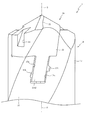
以下、本発明の好ましい実施の形態について、添付図面を参照して説明する。図1は本発明の第1実施の形態におけるスローアウェイ式回転工具1の斜視図である。なお、図1では、ボデー10の軸方向長さの図示が省略されている。
DESCRIPTION OF EXEMPLARY EMBODIMENTS Hereinafter, preferred embodiments of the invention will be described with reference to the accompanying drawings. FIG. 1 is a perspective view of a throw-away
まず、図1を参照して、スローアウェイ式回転工具1の概略構成について説明する。図1に示すように、スローアウェイ式回転工具1は、ボデー10と、そのボデー10に装着される切削ヘッド20とを備えて構成され、ボデー10を保持するホルダ(図示せず)を介してマシニングセンタ等の加工機械の回転力が伝達されることで、被加工物の切削加工を行う回転工具である。
First, a schematic configuration of the throw-away
ボデー10は、加工機械の回転力を切削ヘッド20に伝達するためのものであり、高速度工具鋼から略軸状体に構成され、その一端側が上述したホルダを介して加工機械に取り付けられる。本実施の形態においては、ボデー10の外周面に、切削加工時における切り屑の排出を行うための第1溝11が設けられている。
The
切削ヘッド20は、先端に設けられる切れ刃21によって被加工物の切削加工を行うためのものであり、ボデー10よりも硬質の超硬合金から構成され、ボデー10に着脱可能に装着されている。これにより、切れ刃21が寿命に達した場合でも、他の切削ヘッドと交換することで、切削ヘッド20を再研削する必要なく切削加工を継続することができる。本実施の形態においては、切削ヘッド20も、切削加工時における切り屑の排出を行うための第2溝22が設けられており、切削ヘッド20がボデー10に取り付けられた場合に、第2溝22が第1溝11と連接されるように構成されている。なお、本実施の形態では、切削ヘッド20が2つの切れ刃21と2つの第2溝22とを有している。
The
次に、図2を参照して、ボデー10の詳細構成について説明する。図2はスローアウェイ式回転工具1のボデー10の斜視図である。なお、図2では、ボデー10の軸方向の長さの図示が省略されている。ボデー10は、ランド12を外周面とすると共に第1溝11の一部を側面として延設され第1溝11のねじれ角にあわせて軸心Oの周りに立設された複数(本実施の形態においては2つ)の立設部13と、その立設部13の後端部側に設けられる底部14とを主に備えて構成されている。立設部13は切削ヘッド20を保持する部位であり、軸心Oを中心として等角ピッチ(本実施の形態では180°)で立設されており、切削ヘッド20の凸状連結部23(後述する)が立設部13の内側に挿入される。また、底部14は、ボデー10の軸心Oと直交して形成されており、軸心Oと合致する中心位置に孔部14aが凹設されている。孔部14aは、切削ヘッド20の凸状連結部23(後述する)の後端部23bに凸設される凸部23cが嵌挿される部位である。
Next, the detailed configuration of the
立設部13は、軸心Oを中心とする同一半径の円弧状の曲線の集合として内周壁13aが形成されており、各々の内周壁13aに軸心Oと略直交して溝部13b,13cが凹設されている。溝部13bは一方の立設部13(図2左側)の内周壁13aの底部14近くに凹設されており、溝部13cは他方の立設部13(図2右側)の内周壁13aの先端寄りに凹設されている。即ち、溝部13b,13cは各々の内周壁13aの先端からの距離を異ならせて形成されている。また、溝部13b,13cは、底部14と対向する壁部13d,13eをそれぞれ有している。以上のように、溝部13b,13cが立設部13の内周壁13aに形成されているので、立設部13の厚さ(肉厚)を溝部13b,13cの深さの分だけ薄くすることができる。これにより、外側(軸心Oから離間する方向)へ傾動する立設部13の弾性変形量を増加させることができ、切削ヘッド20の凸状連結部23(後述する)の着脱を容易化できると共に、立設部13による切削ヘッド20の保持力を増大させることができる。
The
立設部13は、軸心Oと略直交し底部14と略平行に形成された第1面13fを、立設部13の先端側で切削加工時のボデー10の回転前方側に備えている。第1面13fには、切削加工時のボデー10の回転後方側に第1面13fとのなす角が略垂直ないしは鋭角のトルク伝達壁13gが立設されている。トルク伝達壁13gの幅は、切削加工時のボデー10の回転方向に対して第1面13fの幅より少し狭めに形成されている。
The standing
内周壁段差面13hはトルク伝達壁13gと稜線を介して交わると共に、軸心Oを中心とする同一半径の円弧状の曲線の集合として第1溝11のねじれ角にあわせて立設部13の先端側に形成される部位である。なお、軸心Oを中心とする内周壁段差面13hの半径は、内周壁13aの半径より大径に構成されている。その結果、内周壁段差面13hは、第1面13fと同一平面上に第1面13fから延設される第2面13iを介して内周壁13aに連設されている。
The inner peripheral
ここで、第1面13f及びトルク伝達壁13gが交わる部分には、第1面13fの幅方向に亘って凹陥部13jが形成されている。第1面13f及びトルク伝達壁13gが交わる部分に凹陥部13jがあることにより、第1面13f及びトルク伝達壁13gの研削等の面加工を容易に行うことができ生産性を向上させる。また、第1面13fはトルク伝達壁13gと反対側に下り勾配のテーパが形成されている。これにより、切削ヘッド20の取り付けの際に、切削ヘッド20の第1受け部25(後述する)を第1面13fに突き当たることなくスライドさせて、第1面13fと接触させることができる。
Here, a recessed
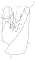
次に、図3を参照して、切削ヘッド20の詳細構成について説明する。図3はスローアウェイ式回転工具1の切削ヘッド20の斜視図である。切削ヘッド20は、図3に示すように、先端に切れ刃21が設けられ、後端(切れ刃21が設けられる側とは反対側)に軸心Oと同軸に凸設される軸状の凸状連結部23を主に備えて構成されている。
Next, a detailed configuration of the cutting
凸状連結部23の外周壁23aは、軸心Oと直交する方向に湾出して形成されると共に、ボデー10の立設部13の内周壁13aと少なくとも一部が接する外周壁摺接部23a1と、平面視して(軸心O方向から見て)切削ヘッド20の第2溝22の縁部22aの一部乃至は内側に外縁が形成された外周壁溝部23a2とを、軸心Oの周りに備えている。外周壁摺接部23a1と外周壁溝部23a2とが連絡する稜線部分には面取り部23a3が形成されている。外周壁摺接部23a1はボデー10(図2参照)の立設部13の内周壁13aと少なくとも一部が接するので、凸状連結部23の外周壁摺接部23a1は立設部13の内周壁13a間に保持される。
The outer
また、外周壁溝部23a2の外縁が、平面視して切削ヘッド20の第2溝22の縁部22aと同一面内あるいは縁部22aより軸心O側に形成されているので、切削ヘッド20とボデー10とを連結した場合に、図1に示すように、外周壁溝部23a2がボデー10の第1溝11から突出することを防止できる。これにより、スローアウェイ式回転工具1は第2溝22及び第1溝11からの切り屑の排出を円滑に行うことができる。さらに、凸状連結部23に面取り部23a3が形成されているので、ボデー10と切削ヘッド20との取り付け時の相対回転をスムーズに行うことができる。
Further, since the outer edge of the outer peripheral wall groove 23a2 is formed in the same plane as the
切削ヘッド20は、凸状連結部23の先端側(後端部23bと反対側)で第1溝11及び第2溝22のねじれ角だけずれた位置に、軸心Oと直交する方向に外周壁23aから突設されランド24と交わる第1受け部25を備えている。また、凸状連結部23の外周壁摺接部23a1には、外周側摺接部23a1の周方向に亘って凸起部26,27が凸設されている。
The cutting
凸起部26は凸状連結部23の後端部23b側に凸設されており、凸起部27は凸状連結部23の先端側(後端部23bと反対側)に凸設されている。凸起部26は、ボデー10(図2参照)の立設部13の内周壁13aに凹設された溝部13bに嵌挿される部位であり、凸起部27は溝部13cに嵌挿される部位である。なお、凸起部26,27は同一の形状で且つ同一の大きさに形成されている。
The protruding
凸起部26は、切削ヘッド20のボデー10への取り付け時において、切削ヘッド20の回転前方側に位置する第1傾斜部26aと、切削ヘッド20の回転後方側に位置する第2傾斜部26bとを備えて構成されている。第1傾斜部26a及び第2傾斜部26bは、軸心Oに向かって下降傾斜する湾曲状に形成されている。凸起部26は第1傾斜部26aを備えているので、切削ヘッド20のボデー10(図2参照)への取り付けのときに、凸起部26を溝部13bへスムーズに挿入できる。また、第2傾斜部26bを備えているので、切削ヘッド20のボデー10からの取り外しのときに、凸起部26を溝部13bからスムーズに脱着できる。なお、凸起部27も同様に、第1傾斜部27a(図示せず)および第2傾斜部27bを備えて構成されており、同様の作用が得られる。
The projecting
また、凸起部26は、凸状連結部23の先端側(後端部23cの反対側)の壁面が軸心Oに向かって下降傾斜して形成される第3傾斜部26cを備えている。凸起部26は第3傾斜部26cを備えているので、立設部13(図2参照)の溝部13bに凸起部26を嵌挿すると、溝部13bの壁部13dが第3傾斜部26cに押圧されることにより、立設部13が弾性変形して外周側にわずかに傾倒し、その反力で凸状連結部23は立設部13の内側に安定に保持される。なお、凸起部27も同様に、第3傾斜部27c(図示せず)を備えて構成されており、同様の作用が得られる。
In addition, the protruding
ここで、凸起部26の第3傾斜部26cから第1受け部25までの軸心Oと平行方向における距離は、ボデー10(図2参照)の溝部13bの壁部13dから第1面13fまでの軸心Oと平行方向における距離と略同一に設定されている。これにより、ボデー10の溝部13bに凸起部26をスライドさせて嵌挿し、溝部13bの壁部13dに凸起部26の第3傾斜部26cが接すると、第1受け部25はボデー10の第1面13fと接することが可能となる。
Here, the distance in the direction parallel to the axis O from the third
凸状連結部23の後端部23bの中心には、位相をずらした状態で凸状連結部23をボデー10(図2参照)の立設部13の内側に挿入したときに、底部14に凹設された孔部14aに挿入される凸部23cが凸設されている。これにより、切削ヘッド20のボデー10への取り付け及び取り外しのときには、孔部14a及び凸部23cを中心にして切削ヘッド20及びボデー10を軸心O回りに相対回転させることができる。
At the center of the
また、切削ヘッド20は、第1受け部25と同一平面上に第1受け部25から延設される第2受け部25aを備えている。第2受け部25aは、凸状連結部23の外周壁摺接部23a1から軸心Oと直交する方向に突設されており、ボデー10(図2参照)の第2面13iと接する部位である。第1受け部25及び第2受け部25aは、軸心Oを中心とする回転対称状に切削ヘッド20の所定位置に形成されている。
Further, the cutting
外周壁段差部25bは、軸心Oからの距離が、軸心Oから外周壁摺接部23a1までの距離より大きく、かつ軸心Oからランド24までの距離より短く設定されると共に、第2受け部25aと交わる部位である。また、外周壁段差部25bは、ボデー10(図2参照)の立設部13の内周壁段差部13hと少なくとも一部が接する部位である。これにより、外周壁段差部25bはボデー10の立設部13の内周壁段差部13h間に保持される。また、外周壁段差部25bには、切削加工時の切削ヘッド20の回転前方側に第1受け部25とのなす角が略垂直ないしは鋭角の伝達壁受け部25cが立設されている。伝達壁受け部25cは、ボデー10(図2参照)のトルク伝達壁13gと接する部位である。
The outer peripheral
上述のように、凸状連結部23は、軸心Oを中心として等角ピッチ(本実施の形態では180°)で形成されると共に、軸心Oから離間する方向に各々の外周壁摺接部23a1から凸設された凸起部26,27を備えている。また、凸状連結部23の先端(後端部23bの反対側)から凸起部26,27のそれぞれの第3傾斜部26c,27cまでの距離は、ボデー10(図2参照)の第1面13f及び第2面13iから溝部13b,13cの壁部13d,13eまでの距離と同一に形成されている。そのため、溝部13b,13cの各々に凸起部26,27の各々を嵌挿できる。
As described above, the convex connecting
ボデー10(図2参照)に切削ヘッド20を取り付けるときは、切削ヘッド20の凸状連結部23を立設部13の内側に位相をずらした状態で挿入する。次いで、切削ヘッド20の先端縁部に形成された外周溝28に図示しない取替工具を挿入し、その取替工具を掴んでボデー10と切削ヘッド20とを相対回転させて、溝部13b,13c内に凸起部26,27を嵌挿する。ボデー10と切削ヘッド20との相対回転は、切削ヘッド20の伝達壁受け部25cがボデー10のトルク伝達壁13gに当接するまで行う。これにより、切削ヘッド20の凸状連結部23が立設部13間に保持される。また、穴あけ加工のときには、ボデー10に伝達された回転トルクが、トルク伝達壁13g及び伝達壁受け部25cを介して切削ヘッド20に伝達される。
When the cutting
ここで、凸起部26,27は凸状連結部23の先端からの距離を異ならせて形成されており、溝部13b,13c(図2参照)は立設部13の第1面13f及び第2面13iからの距離を異ならせて形成されている。従って、凸起部26は溝部13bにしか嵌挿されず、凸起部27は溝部13cにしか嵌挿されない。その結果、凸状連結部23を立設部13に連結できる向きが一通りに決まる。そのため、スローアウェイ式回転工具1のリップハイトや振れのばらつきを抑制できる。その結果、穴あけ加工中に曲がりが生じたり加工孔径が拡大したりすることを防止でき、加工精度のばらつきを抑制できる。また、リップハイトや振れのばらつきを抑制できることから、工具寿命のばらつきを抑制できる。
Here, the protruding
また、2つの凸起部26,27は同一の大きさ及び形状に形成されると共に、軸心Oを中心として等角ピッチで凸状連結部23の外周壁23aに凸設されており、凸状連結部23の軸方向の位置だけが異なっている。これにより、凸起部26,27及び凸状連結部23の重心は軸心O上に位置するように設定される。その結果、軸心Oに対する切削ヘッド20の重心のずれを防止できる。ボデー10よりも硬質の材料で形成される切削ヘッド20の比重はボデー10の比重より大きいので、切削ヘッド20の偏心を防ぐことでスローアウェイ式回転工具1の偏心を防止できる。従って、スローアウェイ式回転工具1に偏心による振れが生じることを防止でき、穴あけ加工中に曲がりが生じたり加工孔径が拡大したりすることを防止できる。よって、加工精度を向上できると共に、加工中の振れを抑制することで、工具寿命を向上できる。
Further, the two protruding
さらに、凸状連結部23に凸設される凸起部26,27は、凸状連結部23の外周壁23aに軸心Oを中心として等角ピッチで形成されると共に、凸状連結部23の先端からの距離を異ならせて形成されているので、重心が軸心O上に位置する切削ヘッド20を容易に製造することができる。これにより、スローアウェイ式回転工具1の生産性を向上できる。
Further, the protruding
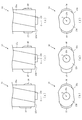
次に、図4を参照して、第2実施の形態、第3実施の形態および第4実施の形態におけるスローアウェイ式回転工具について説明する。第1実施の形態においては、切削ヘッド20の凸状連結部23に凸設された凸起部26,27の大きさ及び形状が同一で、凸状連結部23の先端からの距離が異なる(配置が異なる)場合について説明した。これに対し、第2実施の形態、第3実施の形態および第4実施の形態におけるスローアウェイ式回転工具においては、凸状連結部33,43,53に凸設される凸起部36,37,46,47,56,57の大きさや形状が異なる場合について説明する。なお、図4では、切削ヘッドの凸状連結部33,43,53の一部(後端部23b側)を記載して、凸状連結部33,43,53の先端側の記載を省略している。また、第1実施の形態と同一の部分については同一の符号を付して、その説明を省略する。
Next, the throw-away rotary tool in the second embodiment, the third embodiment, and the fourth embodiment will be described with reference to FIG. In 1st Embodiment, the magnitude | size and shape of the
図4(a)は第2実施の形態における切削ヘッドの凸状連結部33の側面図であり、図4(b)は凸状連結部33の底面図であり、図4(c)は第3実施の形態における切削ヘッドの凸状連結部43の側面図であり、図4(d)は凸状連結部43の底面図であり、図4(e)は第4実施の形態における切削ヘッドの凸状連結部53の側面図であり、図4(f)は凸状連結部53の底面図である。
4A is a side view of the
図4(a)及び図4(b)に示す第2実施の形態における凸状連結部33の凸起部36,37は、凸状連結部33の外周壁33aに軸心Oを中心として等角ピッチで形成されている。凸起部37は、軸方向の長さが、凸起部36の軸方向の長さよりも長く形成されている。凸状連結部33と連結される立設部を備えるボデーは図示していないが、第1実施の形態で説明したように、立設部には凸起部36,37が嵌合する溝部が形成されている。これにより、第2実施の形態は、第1実施の形態の場合と同様に、図示しない立設部に凸状連結部33を連結できる向きが一通りに決まる。これにより、第1実施の形態と同様の作用が得られる。
The protruding
図4(c)及び図4(d)に示す第3実施の形態における凸状連結部43の凸起部46,47は、凸状連結部43の外周壁43aに軸心Oを中心として等角ピッチで形成されている。凸起部46,47は軸方向の長さは同一であるが、外周壁43aからの突出量が、凸起部47は凸起部46より大きく形成されている。凸状連結部43と連結される立設部を備えるボデーは図示していないが、第1実施の形態で説明したように、立設部には凸起部46,47が嵌合する溝部が形成されている。これにより、第3実施の形態は、第1実施の形態の場合と同様に、図示しない立設部に凸状連結部43を連結できる向きが一通りに決まる。これにより、第1実施の形態と同様の作用が得られる。
The protruding
図4(e)及び図4(f)に示す第4実施の形態における凸状連結部53の凸起部56,57は、凸状連結部53の外周壁53aに軸心Oを中心として等角ピッチで形成されている。凸起部56,57は軸方向の長さ及び外周壁53aからの突出量が同一に形成されていが、形状を異ならせて形成されている。即ち、凸起部57は後端部23b側の壁面が軸心Oに向かって下降傾斜して形成されているのに対し、凸起部56は先端側(後端部23bの反対側)の壁面が軸心Oに向かって下降傾斜して形成されている。凸状連結部53と連結される立設部を備えるボデーは図示していないが、第1実施の形態で説明したように、立設部には凸起部56,57が嵌合する溝部が形成されている。これにより、第4実施の形態は、第1実施の形態の場合と同様に、図示しない立設部に凸状連結部53を連結できる向きが一通りに決まる。これにより、第1実施の形態と同様の作用が得られる。さらに、凸起部56,57は形状のみが異なるので、凸起部56,57及び凸状連結部53の重心は軸心O上に位置するように設定される。その結果、スローアウェイ式回転工具の偏心を防止できる。従って、穴あけ加工中に振れが生じることを防止でき、曲がりが生じたり加工孔径が拡大したりすることを防止できる。
4 (e) and FIG. 4 (f), the protruding
以下、本発明をさらに具体化した実施例について説明するが、本発明は以下の実施例に基づいて限定されるものではない。 Examples of the present invention will be described below, but the present invention is not limited to the following examples.
上記第1実施の形態のように構成されるスローアウェイ式回転工具(以下「本発明品」と称す)の振れ及びリップハイトを測定した。振れは、本発明品について、ボデーに切削ヘッドを取り付けた後、ボデーを基準として軸心回りに回転させて、外周コーナ付近のマージンの振回し量を、ダイヤルゲージを使って測定することによって求めた。測定後、ボデーから切削ヘッドを取り外した後に再び同じ切削ヘッドをボデーに取り付け、同様にダイヤルゲージを使って振れを測定した。これを20回繰り返して、測定値を20個得た。 The run-out and lip height of the throw-away rotary tool (hereinafter referred to as “the product of the present invention”) configured as in the first embodiment was measured. For the product of the present invention, after mounting the cutting head on the body, rotate it around the axis centered on the body, and measure the swing amount of the margin near the outer corner using a dial gauge. It was. After measurement, after removing the cutting head from the body, the same cutting head was attached to the body again, and the runout was measured in the same manner using a dial gauge. This was repeated 20 times to obtain 20 measured values.
リップハイトは、本発明品について、ボデーに切削ヘッドを取り付けた後、軸心回りに回転させたときの各切れ刃間の高さの差を、ダイヤルゲージを使って測定することによって求めた。測定後、ボデーから切削ヘッドを取り外した後に再び同じ切削ヘッドをボデーに取り付けて、同様にダイヤルゲージを使ってリップハイトを測定した。これを20回繰り返して、測定値を20個得た。 The lip height of the product of the present invention was determined by measuring the difference in height between the cutting edges when the cutting head was attached to the body and then rotated about the axis using a dial gauge. After the measurement, after removing the cutting head from the body, the same cutting head was attached to the body again, and the lip height was measured in the same manner using a dial gauge. This was repeated 20 times to obtain 20 measured values.
また、比較のため、特許文献1に開示される従来のスローアウェイ式回転工具(立設部および凸状連結部に形成される溝部および凸起部は軸心を対称中心として対称な位置に形成されており、凸起部・溝部それぞれの大きさ・形状は同一であるもの)(以下「従来品」と称す)についても同様にして、振れ及びリップハイトを測定した。 For comparison, the conventional throw-away rotary tool disclosed in Patent Document 1 (the groove portion and the protruding portion formed in the standing portion and the convex connection portion are formed at symmetrical positions with the axis as the center of symmetry. The runout and lip height were also measured in the same manner for the protrusions and grooves having the same size and shape (hereinafter referred to as “conventional product”).
なお、従来品は、溝部および凸起部が軸心に対して対称な関係にあるので、2つの方向から切削ヘッドをボデーに取り付けることができる。そこで、一の方向から切削ヘッドをボデーに取り付けて10個の測定値を得た後、他の方向から切削ヘッドをボデーに取り付けて10個の測定値を得ることにより、20個の測定値を得た。 In the conventional product, the groove portion and the protruding portion are symmetrical with respect to the axis, so that the cutting head can be attached to the body from two directions. Therefore, after obtaining 10 measurement values by attaching the cutting head to the body from one direction, and obtaining 10 measurement values by attaching the cutting head to the body from the other direction, 20 measurement values are obtained. Obtained.
なお、本発明品の各部の寸法は、切削ヘッド及びボデーの直径:16mm、切削ヘッドの先端角:140°、凸状連結部の軸方向の長さ:6mm、外周壁摺接部の直径:6mm、凸起部の軸方向の長さ:1mm、凸起部の半径方向の高さ:0.5mm。また、2つの凸起部は、凸状連結部の先端からの軸方向の距離を異ならせて形成されており、凸状連結部の先端から一方の凸起部までの軸方向の長さ:2.5mm、凸状連結部の先端から他方の凸起部までの軸方向の長さ:4mm。 The dimensions of each part of the product of the present invention are as follows: cutting head and body diameter: 16 mm, cutting head tip angle: 140 °, convex connecting portion axial length: 6 mm, outer wall sliding contact diameter: 6 mm, length of the protruding portion in the axial direction: 1 mm, height of the protruding portion in the radial direction: 0.5 mm. In addition, the two protruding portions are formed with different axial distances from the tip of the convex connecting portion, and the axial length from the tip of the convex connecting portion to one of the protruding portions: 2.5 mm, length in the axial direction from the tip of the convex connecting portion to the other protruding portion: 4 mm.
また、従来品では、2つの凸起部は軸心を対称中心として形成されており、凸状連結部の先端から軸方向の距離がいずれも4mmであり、その他の部位の寸法は、本発明品と同じとされている。 Further, in the conventional product, the two protruding portions are formed with the axis as the center of symmetry, the distance in the axial direction from the tip of the protruding connecting portion is 4 mm, and the dimensions of the other portions are the present invention. It is the same as the product.
以上のように構成される本発明品および従来品の振れ及びリップハイトの各20個の測定値から、平均値(AVG)、最大値(MAX)、最小値(MIN)、標準偏差(σ)を算出した。その結果を表1に示す。 From the 20 measured values of runout and lip height of the product of the present invention and the conventional product configured as described above, the average value (AVG), the maximum value (MAX), the minimum value (MIN), and the standard deviation (σ) Was calculated. The results are shown in Table 1.

以上、実施の形態に基づき本発明を説明したが、本発明は上記実施の形態に何ら限定されるものではなく、本発明の趣旨を逸脱しない範囲内で種々の改良変形が可能であることは容易に推察できるものである。例えば、上記実施の形態で挙げた数値(例えば、各構成の数量や寸法等)は一例であり、他の数値を採用することは当然可能である。 The present invention has been described above based on the embodiments. However, the present invention is not limited to the above embodiments, and various improvements and modifications can be made without departing from the spirit of the present invention. It can be easily guessed. For example, the numerical values (for example, the number and size of each component) given in the above embodiment are merely examples, and other numerical values can naturally be adopted.
上記各実施の形態では、ボデー10が高速度工具鋼製、切削ヘッド20が超硬合金製の場合について説明したが、これらに限定されるものではなく、他の材料を採用することも可能である。他の材料としては、例えば、ボデー10が合金工具鋼製、切削ヘッド20がサーメット製、超微粒子超硬合金製、被覆超硬合金製等を挙げることができる。
In each of the above embodiments, the case where the
上記各形態の形態では、軸心Oに対して所定のねじれ角で第1溝11及び第2溝22が形成されたツイストドリルの場合を説明したが、必ずしもこれに限定されるものではなく、第1溝11及び第2溝22が軸心Oと平行な直刃ドリルに適用することも可能である。また、ボデー10に溝が形成されていないスローアウェイ式回転工具に適用することも可能である。
In the above embodiments, the case of the twist drill in which the
上記各実施の形態では、立設部13の内周壁13aと軸心Oとの距離が、内周壁13aの高さ方向に亘って一定の場合について説明したが、必ずしもこれに限定されるものではない。内周壁13aの高さ方向に漸次増加させ、或いは内周壁13aの高さ方向に亘って漸次減少させるように設定することも可能である。これらの場合は、内周壁13aの大きさに対応させて、切削ヘッド20の凸状連結部23,33,43,53が内周壁13aに接触するように凸状連結部23,33,43,53の太さを調整する。本発明のスローアウェイ式回転工具1は、ボデー10の溝部13b,13cに切削ヘッド20の凸起部26,27,36,37,46,47,56,57が嵌挿することによりボデー10に切削ヘッド20が固定されるので、内周壁13aに凸状連結部23,33,43,53をガタつかないように保持できれば、内周壁13aや凸状連結部23,33,43,53の高さ方向の大きさは切削ヘッド20の固定に影響を与えないからである。同様に、内周壁段差部13hの高さ方向に内径を漸次増加させ、或いは漸次減少させるように設定することも可能である。
In each of the above embodiments, the case where the distance between the inner
上記各実施の形態では、ボデー10の立設部13に溝部13b,13cが凹設され、切削ヘッド20の凸状連結部23,33,43,53に凸起部26,27,36,37,46,47,56,57が凸設されている場合について説明したが、必ずしもこれに限定されるものではない。これらの実施の形態とは逆に、立設部13に凸起部26,27,36,37,46,47,56,57を凸設し、凸状連結部23,33,43,53に溝部13b,13cを凹設することが可能である。また、立設部13に凸起部および溝部を形成し、凸状連結部にそれらと嵌合する溝部および凸起部を形成することも可能である。これらの場合も同様の作用が得られる。
In each of the above-described embodiments, the
上記各実施の形態では、ボデー10に第2面13iが形成され、切削ヘッド20に第2受け部25aが形成された場合について説明したが、必ずしもこれに限定されるものではなく、第2面13i及び第2受け部25aを設けないことも可能である。この場合も、ボデー10のトルク伝達壁13gと切削ヘッド20の伝達壁受け部25cとの接触により、ボデー10を介して切削ヘッド20にマシニングセンタ等の加工機械の回転力を伝達できると共に、ボデー10の第1面13fと切削ヘッド20の第1受け部25との接触により、切削ヘッド20をボデー10に強固に固定できる。
In each of the above embodiments, the case where the second surface 13i is formed on the
上記各実施の形態では、切削ヘッド20の先端の2箇所に切れ刃21が形成されたスローアウェイ式回転工具について説明したが、必ずしもこれに限定されるものではなく、切れ刃が3箇所若しくはそれ以上に形成された切削ヘッド及びボデーを用いることも可能である。この場合はボデーの立設部の数を3個以上に適宜設定することが可能であり、立設部ごとに溝部を設けることが可能である。
In each of the above-described embodiments, the throw-away rotary tool in which the
上記各実施の形態では、ボデー10の底部14に孔部14aが形成され、切削ヘッド20に孔部14aに嵌挿される凸部23cが形成される場合について説明したが、必ずしもこれに限定されるものではなく、孔部14aや凸部23cを設けない場合もある。
In each of the above-described embodiments, the case where the
上記各実施の形態では説明を省略したが、ボデー10及び切削ヘッド20に、切削ヘッド20の取り付け方向を示す刻印やマーキング等の目印を施すことが好ましい。作業者が切削ヘッド20の取り付け方向を容易に認識できるので、取り付け作業性を向上できるからである。
Although description is omitted in each of the above embodiments, it is preferable to mark the
Claims (2)
前記立設部の各々の内周壁または前記凸状連結部の外周壁の少なくとも一方に凹設される少なくとも2以上の溝部と、
それら各溝部に嵌脱可能に形成されると共に、その溝部に相対して、前記立設部の各々の内周壁若しくは前記凸状連結部の外周壁、又は、前記立設部の各々の内周壁および前記凸状連結部の外周壁に凸設される少なくとも2以上の凸起部とを備え、
前記少なくとも2以上の溝部が前記軸心に対して非対称に形成されると共に、前記少なくとも2以上の凸起部が前記軸心に対して非対称に形成されており、
前記凸状連結部に形成される溝部および凸起部の大きさ、形状および配置は、前記切削ヘッドの重心が軸心上に位置するように設定されていることを特徴とするスローアウェイ式回転工具。Cutting having a body having a plurality of standing parts standing around the axis at intervals and a convex connecting part that is made of a material harder than the body and protrudes at the rear end A throw-away rotary tool that connects the convex coupling part and the standing part by inserting the convex coupling part inside the standing part and relatively rotating about an axial center.
At least two or more groove portions recessed in at least one of the inner peripheral wall of each of the standing portions or the outer peripheral wall of the convex connection portion; and
Along with their formed Hamada' possible to the respective groove portions, relative to the groove portion, each of the inner circumferential wall or the outer peripheral wall of the convex coupling portion of the erected portion, or inner peripheral wall of each of the standing portion And at least two or more protruding portions protruding from the outer peripheral wall of the convex connection portion ,
The at least two or more groove portions are formed asymmetrically with respect to the axis, and the at least two or more protruding portions are formed asymmetric with respect to the axis.
The throw-away rotation characterized in that the size, shape, and arrangement of the groove and the protruding portion formed in the convex connection portion are set so that the center of gravity of the cutting head is located on the axis. tool.
Applications Claiming Priority (1)
| Application Number | Priority Date | Filing Date | Title |
|---|---|---|---|
| PCT/JP2009/070567 WO2011070652A1 (en) | 2009-12-08 | 2009-12-08 | Throw-away rotary tool |
Publications (2)
| Publication Number | Publication Date |
|---|---|
| JP4954331B2 true JP4954331B2 (en) | 2012-06-13 |
| JPWO2011070652A1 JPWO2011070652A1 (en) | 2013-04-22 |
Family
ID=44145224
Family Applications (1)
| Application Number | Title | Priority Date | Filing Date |
|---|---|---|---|
| JP2010514171A Active JP4954331B2 (en) | 2009-12-08 | 2009-12-08 | Throw-away rotary tool |
Country Status (5)
| Country | Link |
|---|---|
| US (1) | US20120315101A1 (en) |
| JP (1) | JP4954331B2 (en) |
| CN (1) | CN102159351B (en) |
| DE (1) | DE112009002001B4 (en) |
| WO (1) | WO2011070652A1 (en) |
Families Citing this family (32)
| Publication number | Priority date | Publication date | Assignee | Title |
|---|---|---|---|---|
| CN102847992B (en) * | 2012-09-21 | 2015-07-29 | 株洲钻石切削刀具股份有限公司 | A kind of drilling machining cutter |
| US8882413B2 (en) * | 2012-11-26 | 2014-11-11 | Iscar, Ltd. | Cutting tool and cutting insert with a rearward resilience slit |
| US9409241B2 (en) * | 2012-12-13 | 2016-08-09 | Iscar, Ltd. | Cutting tool and replaceable cutting head having spiral driven surfaces therefor |
| WO2014103972A1 (en) * | 2012-12-28 | 2014-07-03 | 京セラ株式会社 | Drill and method for manufacturing cut product using same |
| DE102013205889B3 (en) | 2013-04-03 | 2014-05-28 | Kennametal Inc. | Coupling structure e.g. cutting head for rotary tool e.g. drilling tool, has coupling pin with clamping faces and stop surfaces that are arranged in different dispensing areas |
| DE102013220884B4 (en) | 2013-10-15 | 2022-02-17 | Kennametal Inc. | Modular carrier tool and tool head |
| KR101509954B1 (en) * | 2013-10-29 | 2015-04-07 | 한국야금 주식회사 | Cutting insert and Indexable Drill |
| DE102014206796B4 (en) * | 2014-04-08 | 2020-10-15 | Kennametal Inc. | Rotary tool, in particular drill and cutting head for such a rotary tool |
| CN104588739B (en) * | 2014-12-30 | 2017-02-22 | 株洲钻石切削刀具股份有限公司 | Rotary machining tool |
| CN104759664A (en) * | 2015-04-21 | 2015-07-08 | 成都锋宜精密工具制造有限公司 | Self-locking type head-replaceable carbide drill |
| DE102015211744B4 (en) | 2015-06-24 | 2023-07-20 | Kennametal Inc. | Rotary tool, in particular a drill, and cutting head for such a rotary tool |
| US9937567B2 (en) * | 2015-10-07 | 2018-04-10 | Kennametal Inc. | Modular drill |
| US10071430B2 (en) | 2015-10-07 | 2018-09-11 | Kennametal Inc. | Cutting head, rotary tool and support for the rotary tool and for the accommodation of the cutting head |
| USD798921S1 (en) | 2015-10-07 | 2017-10-03 | Kennametal Inc. | Cutting head for modular drill |
| USD798922S1 (en) | 2015-10-07 | 2017-10-03 | Kennametal Inc. | Cutting head for rotary drill |
| DE102015220791B4 (en) * | 2015-10-23 | 2020-08-13 | Kennametal Inc. | Rotary tool, in particular drill and cutting head for such a rotary tool |
| KR102360620B1 (en) * | 2016-09-07 | 2022-02-09 | 이스카 엘티디. | A tool shank comprising a head support surface having a central recess provided with resiliently movable adjacent portions. |
| DE102017204452B4 (en) | 2017-03-16 | 2022-02-17 | Kennametal Inc. | rotation tool |
| DE102017205166B4 (en) | 2017-03-27 | 2021-12-09 | Kennametal Inc. | Modular rotary tool and modular tool system |
| EP3427876B1 (en) * | 2017-07-10 | 2022-06-22 | Sandvik Intellectual Property AB | Rotary cutting insert and tool having axial locking member |
| EP3427877B1 (en) * | 2017-07-10 | 2022-09-28 | Sandvik Intellectual Property AB | Rotary cutting insert and tool having a declined axial support surfaces |
| DE102017212054B4 (en) | 2017-07-13 | 2019-02-21 | Kennametal Inc. | Method for producing a cutting head and cutting head |
| US10799958B2 (en) | 2017-08-21 | 2020-10-13 | Kennametal Inc. | Modular rotary cutting tool |
| US11110521B2 (en) | 2018-03-07 | 2021-09-07 | Iscar, Ltd. | Rotary cutting head having a rigid mounting protuberance and rotary cutting tool |
| US11059109B2 (en) | 2018-12-31 | 2021-07-13 | Iscar, Ltd. | Cutting head having torque transmission surfaces on a mounting protuberance and rotary cutting tool having such cutting head |
| JP7373716B2 (en) * | 2019-04-23 | 2023-11-06 | 株式会社不二越 | indexable drill |
| CN112077370A (en) | 2019-06-13 | 2020-12-15 | 肯纳金属印度有限公司 | Indexable drill insert |
| DE102019133212A1 (en) * | 2019-12-05 | 2021-06-10 | Kennametal Inc. | Rotary cutting tool |
| CN110877115B (en) * | 2019-12-11 | 2021-02-26 | 株洲钻石切削刀具股份有限公司 | Drilling tool |
| US11453070B2 (en) | 2020-05-21 | 2022-09-27 | Iscar, Ltd. | Rotatable cutting head having torque transmission surfaces on a mounting protuberance and rotary cutting tool |
| US11951553B2 (en) | 2021-03-29 | 2024-04-09 | Iscar, Ltd. | Rotatable cutting head having tip portion with three radially extending cutting edges forming a rectilinear rotational profile |
| US11819926B2 (en) | 2021-11-16 | 2023-11-21 | Iscar, Ltd | Cutting head having four cutting portions and two convex clamping surfaces, and rotary cutting tool |
Family Cites Families (19)
| Publication number | Priority date | Publication date | Assignee | Title |
|---|---|---|---|---|
| US2158120A (en) * | 1936-02-19 | 1939-05-16 | Charles A Hirschberg | Detachable drill bit |
| US3153356A (en) * | 1962-12-17 | 1964-10-20 | Howard K Dearborn | Gun drill |
| US3215445A (en) | 1962-12-28 | 1965-11-02 | Erickson Tool Co | Tool holder and adapter |
| SE511429C2 (en) * | 1996-09-13 | 1999-09-27 | Seco Tools Ab | Tools, cutting part, tool body for cutting machining and method of mounting cutting part to tool body |
| SE509540C2 (en) * | 1997-06-30 | 1999-02-08 | Seco Tools Ab | Tool |
| IL125766A (en) * | 1998-08-13 | 2002-12-01 | Iscar Ltd | Tool shank and a replaceable cutting head for mounting thereon in a self-clamping manner |
| MXPA01012098A (en) * | 1999-08-03 | 2003-06-30 | Kennametal Inc | Drill bit having a replaceable cutting head. |
| SE519895C2 (en) * | 2000-07-06 | 2003-04-22 | Sandvik Ab | Tip and rotatable tool with interchangeable tip at the tool's cutting end free end |
| DE10042990A1 (en) * | 2000-09-01 | 2002-03-28 | Kennametal Inc | Run-out cutting tool, e.g. B. drills |
| DE10207257B4 (en) * | 2002-02-21 | 2021-02-18 | Kennametal Inc. | Rotary cutting tool with exchangeable cutting insert |
| US6582164B1 (en) * | 2002-02-25 | 2003-06-24 | Kennametal Inc. | Roller twist drill |
| US6935821B2 (en) * | 2002-04-05 | 2005-08-30 | Illinois Tool Works, Inc. | Mushrooming expandable anchor |
| US7131799B2 (en) * | 2003-12-19 | 2006-11-07 | Allied Machine & Engineering Corp. | Cutting insert with helical geometry and holder therefor |
| IL162147A (en) * | 2004-05-24 | 2008-03-20 | Gil Hecht | Drill with releasably mounted cutting head |
| SE527703C2 (en) * | 2004-08-19 | 2006-05-16 | Sandvik Intellectual Property | Rotatable tool and cutting head with axially serrated engaging means |
| IL163679A (en) * | 2004-08-23 | 2009-02-11 | Gil Hecht | Gun-drill |
| US7309196B2 (en) * | 2004-10-05 | 2007-12-18 | Kennametal Inc. | Modular drill |
| IL181295A (en) | 2007-02-12 | 2011-07-31 | Iscar Ltd | Tool with releasably mounted self-clamping cutting head |
| WO2008072840A2 (en) * | 2007-11-05 | 2008-06-19 | Taegutec. Ltd. | Rotary cutting tool |
-
2009
- 2009-12-08 JP JP2010514171A patent/JP4954331B2/en active Active
- 2009-12-08 DE DE112009002001.1T patent/DE112009002001B4/en active Active
- 2009-12-08 WO PCT/JP2009/070567 patent/WO2011070652A1/en active Application Filing
- 2009-12-08 US US12/736,792 patent/US20120315101A1/en not_active Abandoned
- 2009-12-08 CN CN200980128914.3A patent/CN102159351B/en active Active
Also Published As
| Publication number | Publication date |
|---|---|
| JPWO2011070652A1 (en) | 2013-04-22 |
| US20120315101A1 (en) | 2012-12-13 |
| CN102159351B (en) | 2014-12-17 |
| WO2011070652A1 (en) | 2011-06-16 |
| CN102159351A (en) | 2011-08-17 |
| DE112009002001T5 (en) | 2013-02-07 |
| DE112009002001B4 (en) | 2019-09-19 |
Similar Documents
| Publication | Publication Date | Title |
|---|---|---|
| JP4954331B2 (en) | Throw-away rotary tool | |
| JP4850291B2 (en) | Throw-away rotary tool | |
| JP5365298B2 (en) | Drill inserts and insert drills | |
| JP4764421B2 (en) | Drill with removable cutting head | |
| JP4870228B2 (en) | Throw-away rotary tool | |
| JP4407975B2 (en) | Ball end mill | |
| JP4407974B2 (en) | Ball end mill | |
| CN110446575B (en) | Ball end mill | |
| JP2011036977A (en) | Throw-away rotary tool | |
| JP6458851B1 (en) | Reamer | |
| JP2007503320A (en) | End mill tip | |
| TW201244856A (en) | Small-diameter drill | |
| JP2009184043A (en) | Stepped twist drill and method of manufacturing the same | |
| US20140308086A1 (en) | Drill head | |
| JP5614198B2 (en) | drill | |
| JP4449895B2 (en) | Throw-away inserts and throw-away cutting tools | |
| JP6961900B2 (en) | Boring holders and turning tools | |
| JP3597774B2 (en) | Drill with taper | |
| JP2011183534A (en) | Cutting edge replaceable grooving tool | |
| JP2011206904A (en) | Cutting edge replaceable cutting tool | |
| JP5564958B2 (en) | Replaceable cutting edge grooving tool and end face grooving method | |
| JP5560748B2 (en) | Exchangeable grooving tool and peripheral grooving method | |
| JP2006150508A (en) | Cutting tool | |
| JP5471538B2 (en) | Replaceable cutting edge grooving tool and end face grooving method | |
| US20230022961A1 (en) | Drill head and drill |
Legal Events
| Date | Code | Title | Description |
|---|---|---|---|
| TRDD | Decision of grant or rejection written | ||
| A01 | Written decision to grant a patent or to grant a registration (utility model) |
Free format text: JAPANESE INTERMEDIATE CODE: A01 Effective date: 20120313 |
|
| A01 | Written decision to grant a patent or to grant a registration (utility model) |
Free format text: JAPANESE INTERMEDIATE CODE: A01 |
|
| A61 | First payment of annual fees (during grant procedure) |
Free format text: JAPANESE INTERMEDIATE CODE: A61 Effective date: 20120313 |
|
| R150 | Certificate of patent or registration of utility model |
Free format text: JAPANESE INTERMEDIATE CODE: R150 Ref document number: 4954331 Country of ref document: JP Free format text: JAPANESE INTERMEDIATE CODE: R150 |
|
| FPAY | Renewal fee payment (event date is renewal date of database) |
Free format text: PAYMENT UNTIL: 20150323 Year of fee payment: 3 |
|
| R250 | Receipt of annual fees |
Free format text: JAPANESE INTERMEDIATE CODE: R250 |
|
| R250 | Receipt of annual fees |
Free format text: JAPANESE INTERMEDIATE CODE: R250 |
|
| R250 | Receipt of annual fees |
Free format text: JAPANESE INTERMEDIATE CODE: R250 |
|
| R250 | Receipt of annual fees |
Free format text: JAPANESE INTERMEDIATE CODE: R250 |
|
| R250 | Receipt of annual fees |
Free format text: JAPANESE INTERMEDIATE CODE: R250 |
|
| R250 | Receipt of annual fees |
Free format text: JAPANESE INTERMEDIATE CODE: R250 |