JP4953155B2 - Image forming apparatus and method of controlling the apparatus - Google Patents
Image forming apparatus and method of controlling the apparatus Download PDFInfo
- Publication number
- JP4953155B2 JP4953155B2 JP2005314284A JP2005314284A JP4953155B2 JP 4953155 B2 JP4953155 B2 JP 4953155B2 JP 2005314284 A JP2005314284 A JP 2005314284A JP 2005314284 A JP2005314284 A JP 2005314284A JP 4953155 B2 JP4953155 B2 JP 4953155B2
- Authority
- JP
- Japan
- Prior art keywords
- unit
- image forming
- replacement
- condition
- image
- Prior art date
- Legal status (The legal status is an assumption and is not a legal conclusion. Google has not performed a legal analysis and makes no representation as to the accuracy of the status listed.)
- Expired - Fee Related
Links
Images


Description
本発明は、パッチ画像の濃度検出結果に基づき画像形成条件を調整する画像形成装置およびその制御方法に関する。 The present invention relates to an image forming apparatus that adjusts image forming conditions based on a density detection result of a patch image, and a control method therefor.
プリンタ、複写機、ファクシミリ装置などの電子写真方式の画像形成装置では、必要に応じて、所定の画像パターンを有するテスト用の小画像(パッチ画像)を形成するとともに、濃度センサによりその画像濃度を検出し、その検出結果に基づいて、装置各部の動作条件(画像形成条件)を調整することで、所定の画像品質を安定して得られるようにしている。 In electrophotographic image forming apparatuses such as printers, copiers, and facsimile machines, a small test image (patch image) having a predetermined image pattern is formed as needed, and the image density is adjusted by a density sensor. A predetermined image quality can be stably obtained by detecting and adjusting the operation condition (image forming condition) of each part of the apparatus based on the detection result.
例えば、特許文献1に記載の画像形成装置では、装置の電源が投入された直後、あるいはスリープモードが解除された直後に、装置のウォーミングアップを行い、それが完了すると、引き続いて濃度調整処理を実行する。この濃度調整処理では、画像品質に影響を与える濃度制御因子としての帯電バイアスおよび現像バイアスの最適値を、パッチ画像として形成したベタ画像またはハーフトーン画像の濃度検出結果に基づいて算出する。そして、帯電バイアスおよび現像バイアスをそれぞれこうして求めた最適値に設定することで、最適な画像形成条件が得られる。そして、こうして最適化された画像形成条件の下で画像形成動作を実行することで、良好かつ安定した画像品質で画像を形成することができる。
ここで、画像形成装置の情況によっては、上記のような濃度調整処理(パッチ処理)を実行しない方が好ましい場合も考えられる。 Here, depending on the situation of the image forming apparatus, it may be preferable not to execute the density adjustment processing (patch processing) as described above.
例えば、現像ユニット(トナーカートリッジを含む)や感光体ユニットなどの着脱可能なユニットについて、画像品質を保証する等の観点から、交換を推奨する条件が定められている場合がある。この交換推奨条件が成立している場合、そのまま濃度調整処理を実行してしまうと、画像品質が保証されない状態で形成されたパッチ画像に基づき調整処理が実行されてしまうおそれがあるため、この状況では濃度調整処理を実行しない方がよいと考えられる。 For example, conditions that recommend replacement of a detachable unit such as a developing unit (including a toner cartridge) or a photosensitive unit may be defined from the viewpoint of ensuring image quality. If this replacement recommendation condition is satisfied, if the density adjustment process is executed as it is, the adjustment process may be executed based on the patch image formed in a state where the image quality is not guaranteed. Then, it is considered better not to execute the density adjustment processing.
また、現像ユニットについて交換推奨条件が成立している場合、そのまま濃度調整処理を実行してしまうと、濃度調整処理によってトナーが装置内に取り込まれてしまい、その取り込まれたトナーについては画像品質を保証できないおそれがあるため、やはりこの状況では濃度調整処理を実行しない方がよいと考えられる。 Also, if the recommended replacement condition is established for the development unit, if the density adjustment process is executed as it is, the toner is taken into the apparatus by the density adjustment process, and the image quality of the taken toner is reduced. Since there is a possibility that it cannot be guaranteed, it is considered better not to execute the density adjustment process in this situation.
更に、濃度調整処理を実行することで、交換する必要のないユニットや装置自身も消耗することから、不要な濃度調整処理による無駄な消耗を避けるためにも、濃度調整処理の実行可否について適切に判断することが望ましい。 Furthermore, since the unit and the device itself that do not need to be replaced are consumed by executing the density adjustment process, whether or not the density adjustment process can be performed appropriately is also avoided in order to avoid unnecessary consumption due to the unnecessary density adjustment process. It is desirable to judge.
そこで、本発明は、画像形成装置において、濃度調整処理の実行可否を適切に制御することで、画像品質を保証し、無駄な消耗を抑制することを目的とする。 SUMMARY An advantage of some aspects of the invention is that image quality is guaranteed and wasteful consumption is suppressed by appropriately controlling whether or not density adjustment processing can be performed in an image forming apparatus.
本発明の画像形成装置は、画像形成動作を実行する画像形成手段と、前記画像形成手段により形成したパッチ画像の濃度検出結果に基づき、画像形成動作を実行する際の画像形成条件を所定の最適条件に調整する条件制御手段と、所定のタイミングで、着脱可能な所定ユニットについて交換推奨条件が成立しているか否かを判断し、成立している場合に前記所定ユニットの情報を出力する交換推奨手段と、前記画像形成手段、前記条件制御手段、前記交換推奨手段の実行を制御する制御手段とを備えた画像形成装置であって、前記制御手段は、前記所定ユニットについて交換推奨条件が成立していない場合、又は前記所定ユニットについて交換推奨条件が成立しているが、ユーザから前記所定ユニットについて交換を行わないとの入力を受け付けた場合に、前記条件制御手段を実行させることを特徴とする。前記所定ユニットは、現像ユニット又は感光体ユニットのいずれかであることが望ましい。 The image forming apparatus according to the present invention has an image forming unit that executes an image forming operation, and a predetermined optimum image forming condition for executing the image forming operation based on a density detection result of a patch image formed by the image forming unit. Condition control means for adjusting to the condition, and at a predetermined timing, it is determined whether or not the recommended replacement condition is satisfied for a predetermined unit that can be attached and detached, and if it is satisfied, the replacement recommendation that outputs information on the predetermined unit And an image forming apparatus comprising: control means for controlling execution of the image forming means, the condition control means, and the replacement recommendation means, wherein the control means satisfies a replacement recommendation condition for the predetermined unit. If the replacement recommended condition is satisfied for the predetermined unit, the user receives an input indicating that the predetermined unit is not replaced. If digits, characterized in that to execute the condition control means. The predetermined unit is preferably either a developing unit or a photosensitive unit.
好適には、前記交換推奨手段は、前記所定ユニットから所定の品質保証データを検出できない場合、又は前記所定ユニットの消耗品の残量又は寿命が所定値以下である場合に、交換推奨条件が成立していると判断する。 Preferably, the replacement recommendation condition is satisfied when the predetermined quality assurance data cannot be detected from the predetermined unit, or when the remaining amount or life of the consumable of the predetermined unit is less than a predetermined value. Judge that you are doing.
かかる構成によれば、ユーザがそれを望まないかぎり、画像品質の保証がない状態で条件制御手段が実行されてしまったり、条件制御手段の実行により品質保証のないトナーが装置内に取り込まれてしまう状況を防止することができ、その結果、画像品質を適正に保つことができる。更に、このように条件制御手段の実行可否を適切に制御することで、条件制御手段の不要な実行によるトナーや装置自身の無駄な消耗を抑制することが可能となる。 According to such a configuration, unless the user desires it, the condition control means is executed without guaranteeing the image quality, or toner without quality assurance is taken into the apparatus by the execution of the condition control means. Can be prevented, and as a result, the image quality can be kept appropriate. Furthermore, by appropriately controlling whether or not the condition control means can be executed in this way, it is possible to suppress wasteful consumption of toner and the apparatus itself due to unnecessary execution of the condition control means.
好適には、前記交換推奨手段は、前記所定ユニットから所定の品質保証データを検出できない場合、又は前記所定ユニットの消耗品の残量又は寿命が所定値以下である場合に、交換推奨条件が成立していると判断する。この場合、前記交換推奨手段は、ユーザから前記所定ユニットについて交換を行わないとの入力を受け付けた場合、前記所定ユニットについて所定の品質保証データを読み取ることができるか否かの判断を行わないことが望ましい。 Preferably, the replacement recommendation condition is satisfied when the predetermined quality assurance data cannot be detected from the predetermined unit, or when the remaining amount or life of the consumable of the predetermined unit is less than a predetermined value. Judge that you are doing. In this case, the replacement recommendation means does not determine whether or not the predetermined quality assurance data can be read for the predetermined unit when receiving an input from the user that the predetermined unit is not to be replaced. Is desirable.
また好適には、前記交換推奨手段は、電源がONとなったタイミング、前記所定ユニットがセットされたタイミング、所定回数の画像形成動作を実行したタイミングのいずれかに基づいて、交換推奨条件が成立しているか否かを判断する。 Preferably, the replacement recommendation unit satisfies the replacement recommendation condition based on any one of a timing when the power is turned on, a timing when the predetermined unit is set, and a timing when a predetermined number of image forming operations are executed. Judge whether or not.
本発明の画像形成装置の制御方法は、画像形成手段により形成したパッチ画像の濃度検出結果に基づき、画像形成動作を実行する際の画像形成条件を所定の最適条件に調整する条件制御工程と、所定のタイミングで、着脱可能な所定ユニットについて交換推奨条件が成立しているか否かを判断し、成立している場合に前記所定ユニットの情報を出力する交換推奨工程と、前記所定ユニットについて交換推奨条件が成立していない場合、又は前記所定ユニットについて交換推奨条件が成立しているが、ユーザから前記所定ユニットについて交換を行わないとの入力を受け付けた場合に、前記条件制御工程が実行されるように制御する実行制御工程とを備えることを特徴とする。 A control method for an image forming apparatus of the present invention includes a condition control step of adjusting an image forming condition when executing an image forming operation to a predetermined optimum condition based on a density detection result of a patch image formed by an image forming unit; At a predetermined timing, it is determined whether or not a recommended replacement condition is satisfied for a predetermined removable unit, and if it is satisfied, a replacement recommended step for outputting information on the predetermined unit, and a replacement recommended for the predetermined unit. When the condition is not satisfied, or when the recommended replacement condition is satisfied for the predetermined unit, but the user receives an input indicating that the predetermined unit is not to be replaced, the condition control step is executed. And an execution control step for controlling as described above.
本発明の制御方法は、コンピュータにより実施することができるが、そのためのコンピュータプログラムは、CD−ROM、磁気ディスク、半導体メモリ及び通信ネットワークなどの各種の媒体を通じて画像形成装置内のメモリにインストールまたはロードすることができる。 The control method of the present invention can be implemented by a computer, and a computer program therefor is installed or loaded into a memory in the image forming apparatus through various media such as a CD-ROM, a magnetic disk, a semiconductor memory, and a communication network. can do.
本発明によれば、画像形成装置において、濃度調整処理の実行可否を適切に制御することで、画像品質を保証し、無駄な消耗を抑制することができる。 According to the present invention, in an image forming apparatus, by appropriately controlling whether or not density adjustment processing can be performed, it is possible to guarantee image quality and suppress wasteful consumption.
図1は、本発明にかかる画像形成装置の一実施形態を示す図である。また、図2は、図1の画像形成装置の構成を示すブロック図である。本画像形成装置では、ホストコンピュータ100などの外部装置から画像信号が制御ユニット1のメインコントローラ11に与えられると、このメインコントローラ11で該画像信号を解析し、種々の画像処理を施した後、その画像処理済の信号をエンジンコントローラ12に与える。そして、エンジンコントローラ12は、フラッシュメモリ123に記憶されているファームウェアに基づきエンジン部EGの各部を制御して、複写紙、転写紙、用紙およびOHP用透明シートなどのシートSに画像信号に対応する画像を形成する。本画像形成装置は、イエロー(Y)、マゼンタ(M)、シアン(C)、ブラック(K)の4色のトナーを重ね合わせてフルカラー画像を形成する機能、ブラック(K)のトナーのみを用いてモノクロ画像を形成する機能を備えている。
FIG. 1 is a diagram showing an embodiment of an image forming apparatus according to the present invention. FIG. 2 is a block diagram showing the configuration of the image forming apparatus shown in FIG. In this image forming apparatus, when an image signal is given to the
エンジン部EGは、図1に示すように、感光体ユニット2、ロータリー現像部3(イエロー用の現像ユニット(以下「Y現像ユニット」という)3Y、マゼンタ用の現像ユニット(「M現像ユニット」)3M、シアン用の現像ユニット(「C現像ユニット」)3C、ブラック用の現像ユニット(「K現像ユニット」)3Kなど)、中間転写ユニット4、定着ユニット5、露光ユニット8、ファームウェア読み取りユニット10等を含んで構成される。これらのうち2、3Y、3M、3C、3K、4、5、8の各ユニットは、装置本体6に対して着脱自在となっており、各ユニットが装置本体6にセットされた状態で感光体ユニット2の感光体21が図1の矢印方向D1に回転することで、印刷処理が実行される。なお、Y現像ユニット3Y、M現像ユニット3M、C現像ユニット3C、K現像ユニット3Kは、消耗品であるトナーを格納している点で、現像ユニット以外のユニットは、経年により機能が低下し得る点で、消耗品ユニットとして把握することができる。
As shown in FIG. 1, the engine unit EG includes a
感光体ユニット2には、感光体21、帯電部22およびクリーニング部23が収容されており、これらは一体的に装置本体6に対して着脱自在となっている。帯電部22は、図示を省略する帯電バイアス発生部から帯電バイアスが印加されており、感光体21の外周面を均一に帯電させることができる。また、クリーニング部23は、感光体21の回転方向D1における帯電部22の上流側に設けられており、一次転写後に感光体21の外周面に残留付着しているトナーを掻き落とすことで、感光体21の表面クリーニングを行うことができる。
The
帯電部22によって帯電された感光体21の外周面に向けて、露光ユニット8から光ビームLが照射される。露光ユニット8は、エンジンコントローラ12に設けられたレーザドライバ(図示省略)と電気的に接続されており、レーザドライバから与えられる駆動信号に応じて制御されて、光ビームLを感光体21上に露光して画像信号に対応する静電潜像を感光体21上に形成する。
The light beam L is irradiated from the
こうして形成された静電潜像は、ロータリー現像部3によってトナー現像される。ロータリー現像部3は、軸中心に回転自在に設けられた各現像ユニット(Y現像ユニット3Y、M現像ユニット3M、C現像ユニット3C、K現像ユニット3K)、各現像ユニットを回転移動させて予め決められた複数の位置(例えば、感光体21に対する現像位置、ファームウェア読み取りユニット10との通信位置)に位置決めするための機構部33などを含んで構成されている。
The electrostatic latent image formed in this way is developed with toner by the rotary developing unit 3. The rotary developing unit 3 is determined in advance by rotating each developing unit (
現像ユニットの一つがロータリー現像部3の機構部33によって現像位置に位置決めされると、当該現像ユニットのユニットハウジング内に貯留されたトナーが、現像ローラ31に担持されながら搬送される。そして、現像ローラ31に対して所定の現像バイアスを印加することで、現像ローラ31によって担持/搬送されたトナーが感光体21に付着して、静電潜像が顕像化される。こうして、選択された色のトナー像が感光体21の表面に形成される。
When one of the developing units is positioned at the developing position by the
図1では、K現像ユニット3Kが現像位置に位置決めされ、K現像ユニット3Kに設けられた現像ローラ31が感光体21と対向配置されている様子が示されている。
FIG. 1 shows a state in which the K developing unit 3K is positioned at the developing position, and the developing
上記のようにして現像部3で現像されたトナー像は、一次転写領域TR1で、中間転写ユニット4の中間転写ベルト41上に、一次転写される。すなわち、中間転写ユニット4は、複数のローラに掛け渡された中間転写ベルト41と、中間転写ベルト41を回転駆動する駆動部(図示省略)とを備えており、カラー画像をシートSに転写する場合には、感光体21上に形成される各色のトナー像を中間転写ベルト41上に重ね合わせて、カラー画像を形成する一方、単色画像をシートSに転写する場合には、感光体21上に形成されるブラック色のトナー像のみを中間転写ベルト41上に転写して、単色画像を形成する。
The toner image developed by the developing unit 3 as described above is primarily transferred onto the
こうして中間転写ベルト41上に形成された画像は、所定の二次転写領域TR2において、カセット9から取り出されたシートS上に二次転写される。そして、トナー画像が転写されたシートSを、ヒータ(図示省略)が内蔵された定着ユニット5に導入し、ここで加熱しながら圧力を加えることによって、トナーをシートSに定着させる。このようにして画像が形成されたシートSは、装置本体6の上面部に設けられた排出トレイ部に搬送される。
The image thus formed on the
ここで、本実施形態の画像形成装置では、パッチ画像の濃度を検出するために、中間転写ベルト41が掛け渡された一のローラに対向して、濃度センサPSが配置されている。この濃度センサPSは、必要に応じ、中間転写ベルト41の外周面で形成されるトナー画像の画像濃度を測定する。そして、その測定結果に基づき、この装置では、画像品質に影響を与える装置各部の動作条件、例えば各現像ユニットに与える現像バイアスや、光ビームLの強度、さらには装置の階調補正特性などの調整を行っている。
Here, in the image forming apparatus of this embodiment, in order to detect the density of the patch image, the density sensor PS is arranged to face one roller on which the
濃度センサPSは、例えば反射型フォトセンサを用いて、中間転写ベルト41上の所定面積の領域の画像濃度に対応した信号を出力するように構成されている。エンジンコントローラ12は、中間転写ベルト41を周回移動させながら、この濃度センサPSからの出力信号を定期的にサンプリングすることで、中間転写ベルト41上のトナー画像各部の画像濃度を検出することができる。
The density sensor PS is configured to output a signal corresponding to the image density of a predetermined area on the
また、本実施形態の画像形成装置では、各現像ユニットとして、例えば小型のICチップ32がネジや接着剤等によって取り付けられている現像ユニットを用いることができる。また、感光体ユニット2についても同様に、ICチップ32が取り付けられたものを用いることができる。
In the image forming apparatus of the present embodiment, as each developing unit, for example, a developing unit to which a
このICチップ32には、その内部の半導体回路に、現像ユニットの製造ロットデータや、画像形成装置メーカ等が該現像ユニットのトナー等の品質について保証していることを示す品質保証データなどが記憶される。
The
ICチップ32に記憶されている各種データは、所定のタイミングで、読み取りユニット10によって無線で読み出され、エンジンコントローラ12等において所定の制御処理に利用される。このようなICチップ32及び読み取りユニット10は、従来のデータキャリア技術を用いて構成することができる。
Various data stored in the
次に、図2を参照しつつ、図1の画像形成装置の電気的構成について説明する。メインコントローラ11は、ホストインタフェース111、CPU112、ROM113、RAM114およびエンジンインタフェース115などを備えている。このメインコントローラ11では、ホストインタフェース111によってホストコンピュータ100との間の通信処理を行うように構成されており、ホストコンピュータ100から送信された画像信号、所定のプログラムなどを受信する。受信された画像信号などはRAM114に一次的に格納される。
Next, the electrical configuration of the image forming apparatus in FIG. 1 will be described with reference to FIG. The
CPU112は、図示を省略する入出力ポートを介して、装置本体6に取り付けられた操作パネル13と電気的に接続されている。この操作パネル13には、CPU112に対してユーザが種々の指令を与えるために複数のスイッチ131が設けられるとともに、ユーザに対してメッセージや印刷状況などを表示するために表示部132が設けられており、操作パネル13がマンマシンインタフェースとして機能している。
The
また、ROM113には、予めメインコントローラ11用のプログラムが記憶されており、このプログラムにしたがってCPU112およびロジック回路(図示省略)が作動することで、受信した画像信号に対して種々の画像処理を施すことができる。例えば、画像信号に対応する画像内の各画素のRGB成分の階調レベルを示したRGBデータを、対応するCMYK成分の階調レベルを示したCMYKデータに変換する。また、各画素のCMYKデータに対し階調補正を行った後、さらに誤差拡散法、ディザ法、スクリーン法などのハーフトーニング処理を行い、1画素1色当たり例えば8ビットのハーフトーンCMYKデータを作成する。そして、そのハーフトーンCMYKデータを用いて各色画像の露光レーザパルスをパルス幅変調するためのビデオ信号を作成し、エンジンインタフェース115を介してエンジンコントローラ12に出力する。
The
一方、エンジンコントローラ12は、図2に示すように、メインインタフェース121、CPU122、フラッシュメモリ123およびRAM124などを備えている。
On the other hand, the
メインインタフェース121は、メインコントローラ11との間で通信を行うためのものであり、これを介してメインコントローラ11から送信されるコマンドやデータなどを受信する。
The
フラッシュメモリ123は、書き換え可能な不揮発性メモリであり、ファームウェア、各現像ユニットのトナー残量を示すカウンター値、画像形成条件などを記憶している。
The
CPU122は、フラッシュメモリ123に記憶されるファームウェアを実行することにより、エンジン部EGの各部を制御して複写紙、転写紙、用紙およびOHP用透明シートなどのシートSに、画像信号に対応する画像を形成する印刷処理、画像形成条件を調整するパッチ処理、パッチ処理に実行可否を制御する処理(パッチ処理実行制御処理)などを実行する。なお、CPU122は、これらの処理以外にも、画像形成装置が備える一般的な処理、例えばファームウェア書き換え処理などを実行する。
The
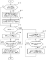
以下、図3〜図5のフローチャートを参照して、本実施形態におけるパッチ実行制御処理、パッチ処理について詳細に説明する。なお、各工程(符号が付与されていない部分的な工程を含む)は、処理内容に矛盾を生じない範囲で任意に順番を変更して又は並列に実行することができる。 Hereinafter, the patch execution control process and the patch process in this embodiment will be described in detail with reference to the flowcharts of FIGS. In addition, each process (including the partial process to which the code | symbol is not provided) can be arbitrarily changed in order in the range which does not produce contradiction in the processing content, or can be performed in parallel.
(パッチ実行制御処理:図3、図4)
画像形成装置の電源がONされると、初期動作の一つとして、CPU122は、パッチ実行制御処理を実行する(S100〜S119)。
(Patch execution control processing: FIGS. 3 and 4)
When the power of the image forming apparatus is turned on, as one of the initial operations, the
まず、CPU122は、各現像ユニットの交換推奨条件の成立有無を示すフラグ(以下、「交換推奨フラグ」という)について、それぞれ「非成立」を示すように初期設定する(S100)。
First, the
次に、CPU122は、セットされている現像ユニットについて交換推奨条件が成立しているか否かをチェックすべく、セットされている現像ユニットのうち一つを選択し(S101)、ロータリー現像部3の機構部33を制御して前記選択した現像ユニットを通信位置に位置決めする(S102)。ここで、通信位置とは、ICチップ32が取り付けられた現像ユニットが当該通信位置にある場合に、読み取りユニット10によってICチップ32に記憶されるデータを無線で読み出すことができるような位置である。
Next, the
次に、CPU122は、前記選択した現像ユニットがICチップ32を備えているか否かを判断する(S103)。
Next, the
例えば、セットされた現像ユニットが備えるICチップ32と通信可能な位置に設けられている読み取りユニット10を制御して、電磁波(チャージ波)を発信させ、所定回数を試みてもICチップ32からの応答信号が得られない場合に、現像ユニットはICチップ32を備えていない(ICチップ32が正常に機能していない場合を含む)と判断することが考えられる。
For example, even if the
ICチップ32を備えていると判断した場合、CPU122は、読み取りユニット10を制御して、前記選択した現像ユニットが備えるICチップ32に記憶されるデータを無線で読み出す(S104)。
If it is determined that the
次に、CPU122は、前記読み出したデータ中に品質保証データが含まれているか(検出できるか)否かを判断する(S105)。
Next, the
品質保証データが含まれている場合、CPU122は、前記選択した現像ユニットについて、画像形成装置メーカ等がトナー等の品質を保証している現像ユニットであると判断する(S106)。
If the quality assurance data is included, the
次に、CPU122は、まだ選択していない現像ユニットがあるか否かを判断し(S107)、未選択の現像ユニットがある場合はS101に再帰し、全て選択済みである場合にはS110の処理へ移行する。
Next, the
一方、ICチップ32を備えていないと判断した場合、又は、前記読み出したデータ中に品質保証データが含まれていない場合、CPU122は、前記選択した現像ユニットについて、画像形成装置メーカ等がトナー等の品質を保証していない現像ユニットであると判断し、交換推奨条件が成立したと判断する(S108)。
On the other hand, if it is determined that the
そして、前記選択した現像ユニットの交換推奨フラグを「成立」に変更し(S109)、S107の処理へ移行する。 Then, the replacement recommendation flag of the selected developing unit is changed to “established” (S109), and the process proceeds to S107.
S107において全て選択済みである場合、CPU122は、フラッシュメモリ123に記憶する各現像ユニットのトナー残量を示すカウンター値を参照し、トナー残量が所定値以下(例えば、カウンター値が0)の現像ユニットがあるかどうかをチェックする(S110)。
When all the selections have been made in S107, the
トナー残量が所定値以下の現像ユニットがある場合、CPU122は、該現像ユニットについて、画像品質を保証できない現像ユニットであると判断し、交換推奨条件が成立したと判断する(S111)。
If there is a developing unit whose remaining amount of toner is equal to or less than the predetermined value, the
そして、トナー残量が所定値以下の現像ユニットの交換推奨フラグを「成立」に変更する(S112)。 Then, the replacement recommendation flag of the developing unit whose remaining toner amount is equal to or less than the predetermined value is changed to “established” (S112).
次に、CPU122は、各現像ユニットの交換推奨フラグをチェックし(S113)、交換推奨フラグが「成立」となっている現像ユニットがない場合は、現像ユニットについて交換推奨条件が成立していないと判断し、S118の処理へ移行する。
Next, the
一方、交換推奨フラグが「成立」となっている現像ユニットがある場合は、その現像ユニットについて交換を推奨すべく、該現像ユニットの情報(例えば、現像ユニットのID情報)をメインコントローラ11に出力する(S114)。そして、現像ユニットの交換、又はメインコントローラ11からの指示を待機する(S115)。
On the other hand, if there is a development unit whose replacement recommendation flag is “established”, information on the development unit (for example, ID information of the development unit) is output to the
メインコントローラ11(CPU112)は、エンジンコントローラ12(CPU122)から現像ユニットの情報を受け付けた場合、表示部132に該現像ユニットの交換を推奨する情報(メッセージ等)を出力する。この際、ユーザは、交換を推奨された現像ユニットについて交換を行わずに画像形成動作を行いたい場合、例えば確認ボタンを押下する等により、その旨を操作パネル13から入力することができる。
When the main controller 11 (CPU 112) receives information on the development unit from the engine controller 12 (CPU 122), the main controller 11 (CPU 112) outputs information (message or the like) that recommends replacement of the development unit to the
S115において現像ユニットが交換された場合、CPU122は、そのことをメインコントローラ11に通知するとともに、新たにセットされた現像ユニットの交換推奨フラグを「非成立」に設定し(S116)、そして、該現像ユニットを選択すべく、S101に再帰する。現像ユニットが交換されたかどうかは、例えば現像ユニットを脱着した場合に電気的にフラグが立つように構成しておき、かかるフラグを参照して判断すればよい。
When the development unit is replaced in S115, the
一方、メインコントローラ11においてユーザから交換推奨対象の現像ユニットについて交換を行わない旨の入力を受け付けて、その結果、S115においてメインコントローラ11から交換推奨対象の現像ユニットの交換を行わずに画像形成動作を行う旨の指示を受け付けた場合、CPU122は、後述するパッチ処理を実行し(S117)、その後、画像形成動作の実行指示を待機する(S118)。
On the other hand, the
なお、メインコントローラ11は、エンジンコントローラ12から現像ユニットが交換されたとの通知を受け付けた場合や、ユーザから交換推奨対象の現像ユニットについて交換を行わない旨の入力を受け付けた場合、対応する現像ユニットの交換推奨メッセージ等を消去することが望ましい。
When the
CPU122は、画像形成動作の指示を受け付けた場合(S118:指示あり)、フラッシュメモリ123に記憶されている画像形成条件を採用して、画像形成動作を実行する(S119)。画像形成動作の終了後は、S118に再帰する。
When the
画像形成動作は、従来と同様である。すなわち、ホストコンピュータ100などの外部装置から画像信号が制御ユニット1のメインコントローラ11に与えられると、メインコントローラ11で該画像信号を解析し、種々の画像処理を施した後、その画像処理済の信号がエンジンコントローラ12に与えられる。エンジンコントローラ12では、フラッシュメモリ123に記憶されているファームウェアに基づきエンジン部EGの各部を制御して、複写紙、転写紙、用紙およびOHP用透明シートなどのシートSに画像信号に対応する画像を形成する。また、形成した画像に応じてフラッシュメモリ123に記憶する各現像ユニットのトナー残量を示すカウンター値を更新する。
The image forming operation is the same as the conventional one. That is, when an image signal is given to the
(パッチ処理:図5)
パッチ処理は、形成される画像を一定の画像品質に保つために、画像形成条件を種々に変更設定しながらパッチ画像を形成してその画像濃度を検出し、その検出結果に基づいて画像形成条件を調整する処理である。本実施形態のパッチ処理では、装置各部の動作条件を決める動作パラメータのうち、画像品質に影響を与える制御因子としての現像バイアス及び露光パワーの調整を行う。なお、制御因子として機能する動作パラメータとしては、上記2つ以外にも種々のものが知られており、それらを用いた画質制御の原理及び制御方法についても多くの公知技術がある。従って、設計に応じてそのような他の制御因子、公知技術を採用して、パッチ処理を構成してもよい。
(Patch processing: Fig. 5)
In patch processing, in order to maintain the image quality to be formed, patch image is formed while changing various image forming conditions and the image density is detected, and the image forming condition is determined based on the detection result. It is a process to adjust. In the patch processing of the present embodiment, the development bias and exposure power are adjusted as control factors that affect the image quality among the operation parameters that determine the operation conditions of each part of the apparatus. Various operation parameters that function as control factors are known in addition to the above two, and there are many known techniques for the principle and control method of image quality control using them. Therefore, the patch processing may be configured by adopting such other control factors and known techniques according to the design.
CPU122は、各トナー色毎に、最適現像バイアス、つまり画像形成動作時に各現像ユニットの現像ローラ31に印加する現像バイアスの最適値を算出する。具体的には、1つのトナー色を選択し(S200)、そのトナー色について、現像バイアスを多段階に変更設定しながら各バイアス値での所定パターンのパッチ画像を形成する(S201)。そして、各パッチ画像の画像濃度を濃度センサPSにより検出する(S202)。なお、このとき、濃度センサPSからの出力が異常な、つまり現像バイアスの設定値より想定される濃度に対応した値から大きく逸脱した値を示した場合には、CPU122は、装置に異常があるものとしてエラーと判断し、所定のエラー処理を実行する。
For each toner color, the
各パッチ画像の画像濃度が求まると、それらの値から現像バイアスと画像濃度との対応関係がわかるので、その関係に基づき、画像濃度が予め定められた目標濃度と一致するような現像バイアスの値、すなわち最適現像バイアスを求める(S203)。ただし、その最適値が当該装置における現像バイアスの可変範囲内になかった場合には、その可変範囲において、算出された最適値に最も近い値を最適現像バイアスとする。 When the image density of each patch image is obtained, the relationship between the development bias and the image density can be determined from these values. Based on this relationship, the value of the development bias that matches the predetermined target density based on the relationship. That is, the optimum developing bias is obtained (S203). However, if the optimum value is not within the variable range of the developing bias in the apparatus, the value closest to the calculated optimum value in the variable range is set as the optimum developing bias.
全てのトナー色について終了するまで、かかるS200〜S203までの処理を繰り返す(S204)。これにより、各トナー色毎の最適現像バイアスが求められる。 The processing from S200 to S203 is repeated until the processing is completed for all toner colors (S204). Thereby, an optimum developing bias for each toner color is obtained.
続いて、各トナー色毎に、最適露光パワー、つまり当該トナー色に対応した静電潜像を感光体21上に形成するときの光ビームLの強度の最適値を算出する(S205〜S209)。ここでの処理は、制御因子が現像バイアスに代えて露光パワーである点を除いて上記した最適現像バイアス算出処理(S200〜S204)と同様であるが、必要に応じて、形成するパッチ画像の画像パターンは異なるものとしてもよい。なお、この場合の現像バイアスの設定値は、先に求めた最適値を用いるのが好ましい。こうして、全てのトナー色について最適現像バイアス及び最適露光パワーがそれぞれ求まると、これらの最適値のセットを当該時点における最適な画像形成条件としてフラッシュメモリ123に記憶し(S210)、パッチ処理を終了する。
Subsequently, for each toner color, an optimum exposure power, that is, an optimum value of the intensity of the light beam L when an electrostatic latent image corresponding to the toner color is formed on the
このように本実施形態では、現像ユニットから品質保証データ(画像形成装置メーカ等がトナー等の品質を保証していることを示すデータ)を読み取ることができない場合や、現像ユニットのトナー残量が少なくなって画像品質を保証できないおそれがある場合に、現像ユニットの交換推奨条件が成立していると判断し、そして、現像ユニットについて交換推奨条件が成立していない場合、又は、現像ユニットについて交換推奨条件が成立しているが、ユーザから該現像ユニットについて交換を行わないとの入力を受け付けた場合(すなわち、ユーザが画像品質の保証がされないおそれがあることを認識した上で画像形成動作の実行を希望する場合)に、パッチ処理を実行するように制御している。従って、ユーザがそれを望まないかぎり、画像形成装置メーカ等による画像品質の保証がない状態でパッチ処理が実行されてしまったり、パッチ処理の実行により品質保証のないトナーが装置内に取り込まれてしまう状況を防止することができ、その結果、画像品質を適正に保つことができる。更に、このようにパッチ処理の実行可否を適切に制御することで、不要なパッチ処理によるトナーや装置自身の無駄な消耗を抑制することが可能となる。 As described above, in the present embodiment, the quality assurance data (data indicating that the image forming apparatus manufacturer or the like guarantees the quality of toner or the like) cannot be read from the developing unit, or the remaining amount of toner in the developing unit is low. When there is a risk that the image quality cannot be guaranteed due to a decrease, it is determined that the recommended replacement condition for the development unit is satisfied, and if the recommended replacement condition for the development unit is not satisfied, or the development unit is replaced. When the recommended condition is satisfied, but the user receives an input indicating that the development unit is not to be replaced (that is, the user recognizes that there is a possibility that the image quality is not guaranteed and the image forming operation is not performed). When it is desired to execute), the patch processing is controlled to be executed. Therefore, unless the user desires it, patch processing is executed without image quality assurance by the image forming apparatus manufacturer or the like, or toner without quality assurance is taken into the apparatus by execution of patch processing. Can be prevented, and as a result, the image quality can be kept appropriate. Furthermore, by appropriately controlling whether or not the patch processing can be executed in this way, it is possible to suppress unnecessary consumption of toner and the apparatus itself due to unnecessary patch processing.
(その他)
本発明は、上記実施形態に限定されることなく種々に変形して適用することが可能である。例えば、S115においてメインコントローラ11から交換推奨対象の現像ユニットの交換を行わない旨の指示を受け付けた場合、その指示があった現像ユニットについてはS101において選択しないようにする(つまり、品質保証データを読み取ることができるか否かの判断を行わない)構成としてもよい。このように構成することで、ユーザが交換を行わないと判断し、その旨一度入力しているにもかかわらず、パッチ実行制御処理を行うたびに交換推奨メッセージ等が出力されてしまうという状態を防ぐことができる。
(Other)
The present invention is not limited to the above-described embodiment, and can be variously modified and applied. For example, when an instruction not to replace the development unit to be recommended for replacement is received from the
また例えば、上記実施形態では、パッチ実行制御処理の主な工程をCPU122が実行する構成としているが、パッチ実行制御処理の一部又は全部の工程をメインコントローラ11(CPU112)やホストコンピュータ100などの外部装置において実行するように構成してもよい。
Further, for example, in the above-described embodiment, the
また例えば、上記実施形態では、電源がONとなったタイミングに基づいて、パッチ実行制御処理を実行する(すなわち、現像ユニットの交換推奨条件が成立しているか否かを判断する)構成としているが、該タイミングに加えて又は代えて、例えば、現像ユニット等がセットされたタイミング、所定回数の画像形成動作を実行したタイミングなど、他のタイミングに基づいてパッチ実行制御処理を実行する構成としてもよい。 Further, for example, in the above-described embodiment, the patch execution control process is executed based on the timing when the power is turned on (that is, it is determined whether the development unit replacement recommended condition is satisfied). In addition to or instead of the timing, the patch execution control process may be executed based on other timings such as a timing when the developing unit is set, a timing when a predetermined number of image forming operations are executed, and the like. .
また例えば、上記実施形態では、パッチ実行制御処理において、現像ユニットに関する交換推奨条件の成立性に基づいてパッチ処理の実行を制御する構成としているが、現像ユニットに加えて又は代えて、他の着脱可能なユニット(例えば、感光体ユニット2、中間転写ユニット4、定着ユニット5、露光ユニット8など)について、画像形成装置メーカ等による品質保証の有無や消耗状態(又は寿命)などに基づく同様の交換推奨条件を設定し、かかる交換推奨条件の成立性に基づいてパッチ処理の実行を制御するように構成してもよい。
Further, for example, in the above-described embodiment, in the patch execution control process, the execution of the patch process is controlled based on the establishment of the recommended replacement condition for the development unit. However, in addition to or in place of the development unit, other attachment / detachment is performed. For possible units (for example,
また例えば、上記実施形態では、現像ユニットのICチップ32から無線で品質保証データを読み出す構成としているが、本発明は必ずしもこのような構成に限られるものではない。例えば、現像ユニットをセットした際に装置本体と機械的に嵌合するようにコネクタを設け、該コネクタ等を介して物理的に接続した状態で現像ユニットの記憶手段から品質保証データを読み出すように構成してもよい。また例えば、品質保証データは、電気的に記録されていなくてもよい。例えば、現像ユニットに、画像形成装置メーカ等が品質を保証していることを示す物理形状を設けたりラベル等を添付しておき、機械的に又は適切なセンサを用いて前記物理形状を検出したりラベル等から所定情報を読み取ることができた場合に、品質保証データを検出できたと判断する構成としてもよい。
Further, for example, in the above embodiment, the quality assurance data is read out wirelessly from the
また例えば、上記実施形態では、フラッシュメモリ123に各現像ユニットのトナー残量を示すカウンター値を記憶しておき、該カウンター値に基づいて交換推奨条件の成立性を判断する構成としているが、例えば、現像ユニットに取付けられたICチップ32に該現像ユニットのトナー残量を記憶するようにし、読み取りユニット10を制御してICチップ32からトナー残量を読み出して、交換推奨条件の成立性を判断する構成としてもよい。
Further, for example, in the above-described embodiment, the
また例えば、上記実施形態では、色ごとに現像を行う4サイクルタイプの画像形成装置について説明しているが、本発明はこのような形態に限定されるものではない。例えば、各色同時に現像を行うタンデムタイプの画像形成装置に対して本発明を適用することも可能である。この場合、各色の現像ユニットに対応させて読み取りユニットを設けるか、又は、読み取りユニットを各現像ユニットと通信可能な位置へ駆動するための機構部を設ける必要がある。 For example, in the above embodiment, a four-cycle type image forming apparatus that performs development for each color has been described, but the present invention is not limited to such a form. For example, the present invention can be applied to a tandem type image forming apparatus that develops each color simultaneously. In this case, it is necessary to provide a reading unit corresponding to each color developing unit or to provide a mechanism for driving the reading unit to a position where it can communicate with each developing unit.
また例えば、レーザプリンタ以外の画像形成装置に適用してもよく、インクジェット方式の画像形成装置、複写機、ファクシミリ装置、いわゆるダムプリンタまたはホストベースドプリンタと称されるファームウェアの機能を制限した画像形成装置など、画像形成装置全般に適用することができる。 Further, for example, the present invention may be applied to an image forming apparatus other than a laser printer, and an image forming apparatus that restricts the function of firmware called an ink jet type image forming apparatus, a copying machine, a facsimile apparatus, a so-called dumb printer or a host-based printer The present invention can be applied to all image forming apparatuses.
1…制御ユニット、11…メインコントローラ、12…エンジンコントローラ、123…フラッシュメモリ、2…感光体ユニット、3…ロータリー現像部、3Y、3M、3C、3K…現像ユニット、32…ICチップ、33…機構部、10…読み取りユニット
DESCRIPTION OF
Claims (6)
前記画像形成手段により形成したパッチ画像の濃度検出結果に基づき、画像形成動作を実行する際の画像形成条件を所定の最適条件に調整する条件制御手段と、
所定のタイミングで、着脱可能な感光体ユニットについて交換推奨条件が成立しているか否かを判断し、成立している場合に前記感光体ユニットの交換推奨条件が成立していることを示す情報を出力する交換推奨手段と、
前記画像形成手段、前記条件制御手段、前記交換推奨手段の実行を制御する制御手段とを備えた画像形成装置であって、
前記制御手段は、前記感光体ユニットについて交換推奨条件が成立していない場合、又は前記感光体ユニットについて交換推奨条件が成立しているが、ユーザから前記感光体ユニットについて交換を行わないとの入力を受け付けた場合に、前記条件制御手段を実行させ、前記感光体ユニットについて交換推奨条件が成立し、ユーザから前記感光体ユニットについて交換を行うとの入力を受け付けた場合に、前記感光体ユニットが交換されるのを待機し、交換後に、交換された前記感光体ユニットについて前記交換推奨手段を実行させることを特徴とする画像形成装置。 An image forming means for performing an image forming operation;
Condition control means for adjusting the image forming condition when executing the image forming operation to a predetermined optimum condition based on the density detection result of the patch image formed by the image forming means;
At a predetermined timing, it is determined whether or not the recommended replacement condition for the removable photoconductor unit is satisfied, and information indicating that the recommended replacement condition for the photoconductor unit is satisfied when it is satisfied. Replacement recommendation means to output,
An image forming apparatus comprising: the image forming unit; the condition control unit; and a control unit that controls execution of the replacement recommendation unit,
The control means inputs when the recommended replacement condition for the photosensitive unit is not satisfied, or when the recommended replacement condition is satisfied for the photosensitive unit, but the user does not replace the photosensitive unit. Is received, the condition control means is executed, and when the recommended replacement condition is established for the photosensitive unit, and the input to replace the photosensitive unit is received from the user, the photosensitive unit is An image forming apparatus characterized by waiting for replacement, and causing the replacement recommendation means to be executed for the replaced photoconductor unit after replacement.
所定のタイミングで、着脱可能な感光体ユニットについて交換推奨条件が成立しているか否かを判断し、成立している場合に前記感光体ユニットの交換推奨条件が成立していることを示す情報を出力する交換推奨工程と、
前記感光体ユニットについて交換推奨条件が成立していない場合、又は前記感光体ユニットについて交換推奨条件が成立しているが、ユーザから前記感光体ユニットについて交換を行わないとの入力を受け付けた場合に、前記条件制御工程が実行されるように制御し、前記感光体ユニットについて交換推奨条件が成立し、ユーザから前記感光体ユニットについて交換を行うとの入力を受け付けた場合に、前記感光体ユニットが交換されるのを待機し、交換後に、交換された前記感光体ユニットについて前記交換推奨工程が実行されるように制御する実行制御工程とを備えることを特徴とする画像形成装置の制御方法。 A condition control step of adjusting the image forming condition when executing the image forming operation to a predetermined optimum condition based on the density detection result of the patch image formed by the image forming means;
At a predetermined timing, it is determined whether or not the recommended replacement condition for the removable photoconductor unit is satisfied, and information indicating that the recommended replacement condition for the photoconductor unit is satisfied when it is satisfied. Recommended replacement process to output,
When the recommended replacement condition for the photoconductor unit is not satisfied, or when the recommended replacement condition for the photoconductor unit is satisfied, but an input from the user not to replace the photoconductor unit is received The photosensitive unit is controlled so that the recommended condition for replacement is established for the photoconductor unit, and the photoconductor unit receives an input from the user to replace the photoconductor unit. A control method for an image forming apparatus, comprising: an execution control step of waiting for replacement and performing control so that the replacement recommendation step is executed for the replaced photoconductor unit after replacement.
Priority Applications (1)
| Application Number | Priority Date | Filing Date | Title |
|---|---|---|---|
| JP2005314284A JP4953155B2 (en) | 2005-10-28 | 2005-10-28 | Image forming apparatus and method of controlling the apparatus |
Applications Claiming Priority (1)
| Application Number | Priority Date | Filing Date | Title |
|---|---|---|---|
| JP2005314284A JP4953155B2 (en) | 2005-10-28 | 2005-10-28 | Image forming apparatus and method of controlling the apparatus |
Publications (2)
| Publication Number | Publication Date |
|---|---|
| JP2007121715A JP2007121715A (en) | 2007-05-17 |
| JP4953155B2 true JP4953155B2 (en) | 2012-06-13 |
Family
ID=38145619
Family Applications (1)
| Application Number | Title | Priority Date | Filing Date |
|---|---|---|---|
| JP2005314284A Expired - Fee Related JP4953155B2 (en) | 2005-10-28 | 2005-10-28 | Image forming apparatus and method of controlling the apparatus |
Country Status (1)
| Country | Link |
|---|---|
| JP (1) | JP4953155B2 (en) |
Families Citing this family (1)
| Publication number | Priority date | Publication date | Assignee | Title |
|---|---|---|---|---|
| JP2015060046A (en) * | 2013-09-18 | 2015-03-30 | コニカミノルタ株式会社 | Image formation device, image formation method and program |
Family Cites Families (6)
| Publication number | Priority date | Publication date | Assignee | Title |
|---|---|---|---|---|
| JPH0792630B2 (en) * | 1988-01-11 | 1995-10-09 | インターナショナル・ビジネス・マシーンズ・コーポレーション | office supply |
| JP3476399B2 (en) * | 1999-10-12 | 2003-12-10 | 富士写真フイルム株式会社 | Cartridge life detecting method, apparatus and system, cartridge and storage medium |
| JP4038995B2 (en) * | 2001-04-23 | 2008-01-30 | カシオ電子工業株式会社 | Consumables with reproduction state identification function and image forming apparatus |
| JP2005003954A (en) * | 2003-06-12 | 2005-01-06 | Konica Minolta Business Technologies Inc | Image forming apparatus, maintenance program for image forming apparatus and maintenance method for image forming apparatus |
| JP4016957B2 (en) * | 2004-03-05 | 2007-12-05 | セイコーエプソン株式会社 | Image forming apparatus and image forming method |
| JP2005297328A (en) * | 2004-04-09 | 2005-10-27 | Fuji Xerox Co Ltd | Control method of image forming apparatus and image forming apparatus |
-
2005
- 2005-10-28 JP JP2005314284A patent/JP4953155B2/en not_active Expired - Fee Related
Also Published As
| Publication number | Publication date |
|---|---|
| JP2007121715A (en) | 2007-05-17 |
Similar Documents
| Publication | Publication Date | Title |
|---|---|---|
| JP4831198B2 (en) | Image forming apparatus | |
| JP4447887B2 (en) | Color image forming apparatus and color stabilization control method | |
| JP2009210774A (en) | Image forming apparatus | |
| JP2006201613A (en) | Image forming apparatus and its control method | |
| JP5060174B2 (en) | Image forming apparatus | |
| JP2008151855A (en) | Image forming device and image forming method | |
| JP2012048054A (en) | Image forming device, color correction processing method, image processing program, and computer-readable recording medium | |
| JP2006195246A (en) | Image forming apparatus | |
| JP4953155B2 (en) | Image forming apparatus and method of controlling the apparatus | |
| JP2010002537A (en) | Image forming apparatus, control method of image forming apparatus, and control program for the image forming apparatus | |
| JP2006171138A (en) | Image forming apparatus, toner counter and toner consumption calculating method | |
| JP4867570B2 (en) | Image forming apparatus and image forming method | |
| JP2011141437A (en) | Image forming apparatus | |
| JP5170149B2 (en) | Image forming apparatus, image forming system, printer driver, and correction control program | |
| JP2010054626A (en) | Image forming apparatus, controller, and program | |
| US20200241438A1 (en) | Image forming apparatus and control method of image forming apparatus | |
| JP2004109318A (en) | Image forming apparatus | |
| JP4239966B2 (en) | Image forming apparatus | |
| JP2006309140A (en) | Image forming apparatus and method | |
| JP2010217601A (en) | Image forming device, and method of controlling the same | |
| JP2006231697A (en) | Image forming device and firmware overwriting method | |
| JP4539669B2 (en) | Printing device | |
| JP2020003637A (en) | Image forming apparatus | |
| JP2007225981A (en) | Image forming apparatus and its control method | |
| JP2006272551A (en) | Image forming apparatus and method for controlling its apparatus |
Legal Events
| Date | Code | Title | Description |
|---|---|---|---|
| A621 | Written request for application examination |
Free format text: JAPANESE INTERMEDIATE CODE: A621 Effective date: 20080618 |
|
| A977 | Report on retrieval |
Free format text: JAPANESE INTERMEDIATE CODE: A971007 Effective date: 20110201 |
|
| A131 | Notification of reasons for refusal |
Free format text: JAPANESE INTERMEDIATE CODE: A131 Effective date: 20110210 |
|
| A521 | Written amendment |
Free format text: JAPANESE INTERMEDIATE CODE: A523 Effective date: 20110411 |
|
| A131 | Notification of reasons for refusal |
Free format text: JAPANESE INTERMEDIATE CODE: A131 Effective date: 20110624 |
|
| A521 | Written amendment |
Free format text: JAPANESE INTERMEDIATE CODE: A523 Effective date: 20110708 |
|
| TRDD | Decision of grant or rejection written | ||
| A01 | Written decision to grant a patent or to grant a registration (utility model) |
Free format text: JAPANESE INTERMEDIATE CODE: A01 Effective date: 20120220 |
|
| A01 | Written decision to grant a patent or to grant a registration (utility model) |
Free format text: JAPANESE INTERMEDIATE CODE: A01 |
|
| R150 | Certificate of patent or registration of utility model |
Ref document number: 4953155 Country of ref document: JP Free format text: JAPANESE INTERMEDIATE CODE: R150 Free format text: JAPANESE INTERMEDIATE CODE: R150 |
|
| A61 | First payment of annual fees (during grant procedure) |
Free format text: JAPANESE INTERMEDIATE CODE: A61 Effective date: 20120304 |
|
| FPAY | Renewal fee payment (event date is renewal date of database) |
Free format text: PAYMENT UNTIL: 20150323 Year of fee payment: 3 |
|
| S531 | Written request for registration of change of domicile |
Free format text: JAPANESE INTERMEDIATE CODE: R313531 |
|
| R350 | Written notification of registration of transfer |
Free format text: JAPANESE INTERMEDIATE CODE: R350 |
|
| LAPS | Cancellation because of no payment of annual fees |