JP4952284B2 - Bearing sealing device and bearing unit - Google Patents
Bearing sealing device and bearing unit Download PDFInfo
- Publication number
- JP4952284B2 JP4952284B2 JP2007034540A JP2007034540A JP4952284B2 JP 4952284 B2 JP4952284 B2 JP 4952284B2 JP 2007034540 A JP2007034540 A JP 2007034540A JP 2007034540 A JP2007034540 A JP 2007034540A JP 4952284 B2 JP4952284 B2 JP 4952284B2
- Authority
- JP
- Japan
- Prior art keywords
- seal
- bearing
- split
- sealing device
- engaged
- Prior art date
- Legal status (The legal status is an assumption and is not a legal conclusion. Google has not performed a legal analysis and makes no representation as to the accuracy of the status listed.)
- Active
Links
Images


Description
本発明は、連続鋳造設備などに適用可能な分割型転がり軸受ユニット等のための密封装置及び軸受ユニットに関する。 The present invention relates to a sealing device and a bearing unit for a split type rolling bearing unit or the like that can be applied to a continuous casting facility or the like.
連続鋳造設備は、回転力を伝えるための駆動ロール及び非駆動ロールを備え、操業時のブレークアウト等のアクシデントを防ぐためにロールは小径化され、ロールピッチを詰めて、セグメント内に多数のロールを配置してロール端には支持軸受が配されている。また、駆動ロールが小径化されたことによる軸の強度不足を補うため、中央に支持軸受が配置されている。また、非駆動ロールも軽圧下を行なうことから軸の強度不足を補うため、中央に支持軸受が配置されている。 The continuous casting equipment is equipped with a driven roll and a non-driven roll to transmit the rotational force, and the roll is reduced in diameter to prevent accidents such as breakout during operation. A support bearing is arranged at the end of the roll. Further, a support bearing is disposed in the center in order to compensate for the insufficient strength of the shaft due to the reduced diameter of the drive roll. Further, since the non-driving roll is also lightly reduced, a support bearing is arranged at the center in order to compensate for the insufficient strength of the shaft.
ロール中央に配置される支持軸受のネック径はロール径より細くなっているためロールは杵型の形状を模している。杵型の形状をしたロールの中央には、支持軸受を軸端から組み込めないので、金属材料の部品は軸心方向に二分割し、ゴム材料の部品は軸心方向に向けて一箇所分割し、軸心と直角の径方向から組み込むようになっている(例えば、下記特許文献1参照)。
Since the neck diameter of the support bearing arranged in the center of the roll is smaller than the roll diameter, the roll imitates a bowl shape. Since the support bearing cannot be assembled from the shaft end in the center of the saddle-shaped roll, the metal material part is divided into two parts in the axial direction and the rubber material part is divided into one part in the axial direction. These are incorporated from the radial direction perpendicular to the axis (for example, see
上述のような支持軸受に対する潤滑は、集中給脂やオイルアンドエアーシステムで行われるが、近年は、環境問題や潤滑剤の削減等から、潤滑を終えた潤滑剤は回収されている。潤滑剤の回収は軸箱内の排脂管から戻すので、軸箱内には大きな背圧が生じ、軸箱内の内圧を保持するためシールには大きな圧力負担がある。前述のシールは軸心方向に向けて一箇所分割して組み込まれるため、軸箱内の圧力の増大でシールリップで分割面が開いたり、シールリップの回転摺動抵抗でシール本体の共回りが生じてしまう。 Lubricating the support bearing as described above is performed by centralized lubrication or an oil-and-air system. However, in recent years, lubricants that have been lubricated have been recovered due to environmental problems and reduction of lubricants. Since the recovery of the lubricant is returned from the degreaser pipe in the axle box, a large back pressure is generated in the axle box, and a large pressure load is applied to the seal to maintain the inner pressure in the axle box. Since the above-mentioned seal is divided into one part in the axial direction and incorporated, the split surface is opened by the seal lip when the pressure in the shaft box increases, or the seal body rotates together with the rotational sliding resistance of the seal lip. It will occur.
下記特許文献2は、連続鋳造設備のピンチロール支持部において使用される回転軸受ユニットを開示するが、シールの回り止めやシールの分割合せ面の状態に関する記載はない。また、下記特許文献3,4は、シールの回り止めに関する記載があるが、シールの分割合せ面の状態の記載はない。また、下記特許文献5は、シール本体の組み込み性に関する記載はあるが、シールの回り止めの記載はない。
分割されたシールでは、外周面と締め代をもって摺動するシールリップと回転側の溝に装着さたシール本体が、軸箱の内圧の負荷の増大でシールリップの回転摺動抵抗を受け、そのときシールの分割面には回転方向に縮む側と延ばされる側が生じ、シールリップで分割面に隙間が生じて異物や冷却水が侵入してしまう。また、通常の軸シールに比べ外周面に締め代をもって摺動するので、回転摺動抵抗が大きく、更に、軸箱内の内圧を高めてシールに大きな背圧が生じさせているので、回転摺動抵抗が増大し、シールがつれ回る所謂共回りを生じてシールリップで分割面に隙間が発生したり、シールリップが損傷してシール機能を低下させたり、シール本体に磨耗が生じて、シール本体と溝に隙間が生じて異物や冷却水の侵入が起きる。このため、支持軸受に異物や冷却水が侵入し、錆びを発生させたり、潤滑状態が悪くなるため軸受の短寿命化の問題が生じてしまう。 In the divided seal, the seal lip that slides with the outer peripheral surface and the tightening allowance and the seal body mounted in the groove on the rotation side are subjected to the rotational sliding resistance of the seal lip due to the increase in the internal pressure load of the axle box, In some cases, the split surface of the seal has a side that contracts in the rotational direction and an extended side, and a gap is generated in the split surface by the seal lip, and foreign matter and cooling water enter. In addition, since it slides on the outer peripheral surface with a tightening margin compared to a normal shaft seal, the rotational sliding resistance is large, and furthermore, the internal pressure in the shaft box is increased to generate a large back pressure on the seal. Dynamic resistance increases, so-called co-rotation that causes the seal to swell, causing a gap on the split surface with the seal lip, damage to the seal lip, lowering the seal function, and wear on the seal body, A gap is formed between the main body and the groove, and foreign matter or cooling water enters. For this reason, foreign matter and cooling water intrude into the support bearing, causing rust, and the lubrication state is deteriorated, resulting in a problem of shortening the life of the bearing.
本発明は、上述のような従来技術の問題に鑑み、軸受において分割部を有するシールの密封性の改良及びシールの密封性を阻害する共回りの防止を実現可能な軸受用密封装置及び軸受ユニットを提供することを目的とする。 SUMMARY OF THE INVENTION In view of the above-described problems of the prior art, the present invention provides a bearing sealing device and bearing unit capable of improving the sealing performance of a seal having a split portion in the bearing and preventing co-rotation that impairs the sealing performance of the seal. The purpose is to provide.
上記目的を達成するために、本発明による軸受用密封装置は、弾性材料からなるシール本体と軸受の外輪側または軸箱側の摺動面に対し摺動するリップ部とを有するシールと、前記シール本体を前記軸受の内輪側に対し円周方向に固定する固定手段と、を備える軸受用密封装置であって、前記シールは、円周方向に分離可能に一箇所に設けられた分割部と、前記分割部を挟んでかつ前記分割部に近い前記シール本体の内周面に設けられた2つの係合部と、を有し、前記軸受は、前記各係合部が係合する2つの被係合部を設け前記シール本体を嵌め込むシール溝を内輪に有し、前記シールの係合部を前記シール溝の被係合部に係合させて前記シールを前記シール溝に嵌め込んだ状態で、前記シールが前記分割部を挟んだ各係合部間の短い周長側で弾性変形して前記分割部の分割面間に圧縮力が加わるように構成され、前記シールの長い周長側において線状または細い板状の金属が前記シール本体の内部に埋め込まれ、前記線状または細い板状の金属の両先端が前記係合部に入り込んでいることを特徴とする。 To achieve the above object, a bearing sealing device according to the present invention includes a seal having a seal body made of an elastic material and a lip portion that slides on a sliding surface on the outer ring side or the axle box side of the bearing, Fixing means for fixing a seal body in a circumferential direction to the inner ring side of the bearing, wherein the seal is a split part provided at one place so as to be separable in the circumferential direction; Two engagement portions provided on the inner peripheral surface of the seal body close to the division portion and sandwiching the division portion, and the bearing has two engagement portions with which the respective engagement portions are engaged. The inner ring has a seal groove in which an engaged portion is provided and the seal body is fitted, and the seal is fitted in the seal groove by engaging the engagement portion of the seal with the engaged portion of the seal groove. In the state, the seal has a short peripheral side between the engaging portions sandwiching the divided portion Is configured to be elastically deformed compressive force is applied between the divided surfaces of the divided parts, a linear or thin plate-like metal in a long perimeter side of the seal is embedded inside the seal body, said linear Or both the front-end | tips of a thin plate-shaped metal have penetrated into the said engaging part, It is characterized by the above-mentioned.
この軸受用密封装置によれば、シールの係合部をシール溝の被係合部に係合させてシールをシール溝に嵌め込んだ状態で、シールが分割部を挟んだ各係合部間の短い周長側で弾性変形して分割部の分割面間に圧縮力が加わるので、分割部で分割面が互いに常に圧縮力を受け合い、分割面が閉じたままとなり、分割面に隙間が生じることがなくなり、シールの分割部における密封性が良好となる。このようにして、分割部を有するシールの密封性を改良し向上させることができる。 According to this bearing sealing device, the seal is engaged with the engaged portion of the seal groove, and the seal is fitted in the seal groove. Since the elastic surface is deformed on the short circumference side and a compressive force is applied between the split surfaces of the split portion, the split surfaces always receive the compressive force in the split portion, the split surfaces remain closed, and a gap is generated in the split surface This eliminates the problem and improves the sealing performance at the divided portion of the seal. In this way, it is possible to improve and improve the sealing performance of the seal having the divided portion.
上記軸受用密封装置において前記シールの分割部を挟んだ各係合部間の短い周長側の周長が前記シール溝の各被係合部間の短い周長側の周長よりも若干長く設定されていることで、分割部の分割面間に圧縮力が加わるようにできる。 In the bearing sealing device, the short circumferential length between the engaging portions sandwiching the seal split portion is slightly longer than the short circumferential length between the engaged portions of the seal groove. By being set, a compressive force can be applied between the dividing surfaces of the dividing portion.
また、前記シールの分割部を挟んだ各係合部間の短い周長側の円弧ピッチ角度θ1が前記シール溝の各被係合部間の短い周長側の円弧ピッチ角度θ2よりも大きく設定されていることで、分割部の分割面間に圧縮力が加わるようにできる。 In addition, the short circumferential arc pitch angle θ1 between the engaging portions sandwiching the split portion of the seal is set larger than the short circumferential arc pitch angle θ2 between the engaged portions of the seal groove. Thus, a compressive force can be applied between the split surfaces of the split portions.
また、前記シールの長い周長側において線状または細い板状の金属が前記シール本体の内部に埋め込まれていることにより、リップ部における回転摺動抵抗が増大しても、シール本体の延びや縮みが抑制され、シールの共回りを抑制し、シール溝におけるシール本体の磨耗を防止できるので、シール本体とシール溝との間の密封性が損なわれることがない。 Also, the more and this to seal a long perimeter side linear or thin plate-like metal in is embedded inside the seal body, even if the rotation sliding resistance of the lip portion is increased, the seal body Since expansion and contraction are suppressed, co-rotation of the seal is suppressed, and wear of the seal body in the seal groove can be prevented, sealing performance between the seal body and the seal groove is not impaired.
この場合、前記線状または細い板状の金属の両先端が前記係合部に入り込んでいることにより、シール本体の凸部が線状または細い板状の金属で補強され、凸部が弾性材料単体の回転摺動抵抗を受けての欠損及びシールの共回りの発生を防ぐことができる。 In this case, more and this both tips of the linear or thin plate-like metal intrudes into the engagement portion, the convex portion of the seal body is reinforced by a linear or a thin plate-like metal, convex portion It is possible to prevent the occurrence of chipping and co-rotation of the seal due to the rotational sliding resistance of the elastic material alone.
また、前記シールの係合部が突き出た凸部に構成され、前記シール溝の被係合部が前記凸部に対応した凹部に構成されることが好ましい。 Further, it is preferable that the engaging portion of the seal is formed as a protruding portion, and the engaged portion of the seal groove is formed as a recessed portion corresponding to the protruding portion.
本発明によるもう1つの軸受用密封装置は、弾性材料からなるシール本体と軸受の外輪側または軸箱側の摺動面に対し摺動するリップ部とを有するシールと、前記シール本体を前記軸受の内輪側に対し円周方向に固定する固定手段と、を備える軸受用密封装置であって、前記シールは、円周方向に分離可能に一箇所に設けられた分割部と、前記シールの分割部を挟んでかつ前記分割部に近い前記シール本体の内周面に設けられた2つの係合部と、を有し、前記軸受は、前記各係合部が係合する2つの被係合部を設け前記シール本体を嵌め込むシール溝を内輪に有し、前記シールの分割部を挟んだ周長の短い部分以外の長い周長側において線状または細い板状の金属が前記シール本体の内部に埋め込まれ、前記線状または細い板状の金属の両先端が前記係合部に入り込んでいることを特徴とする。 Another bearing sealing device according to the present invention includes a seal body made of an elastic material, a seal having a lip portion that slides against a sliding surface on the outer ring side or the axle box side of the bearing, and the seal body is attached to the bearing. A sealing means for fixing to the inner ring side of the inner ring side in a circumferential direction, wherein the seal is divided in one place so as to be separable in the circumferential direction, and the seal is divided Two engaging portions provided on the inner peripheral surface of the seal body close to the dividing portion and sandwiching the portion, and the bearing has two engaged portions with which the engaging portions engage And a seal groove into which the seal body is fitted is formed in the inner ring, and a linear or thin plate-like metal on the long circumferential side other than the short circumferential part sandwiching the divided part of the seal is formed on the seal body. embedded therein, both ahead of the linear or thin plate-like metal There characterized in that it enters into the engagement portion.
この軸受用密封装置によれば、シールの分割部を挟んだ周長の短い部分以外の長い周長側において線状または細い板状の金属がシール本体の内部に埋め込まれているので、リップ部における回転摺動抵抗が増大しても、シール本体の延びや縮みが抑制され、シールの共回りを抑制し、シール溝におけるシール本体の磨耗を防止できるので、シール本体とシール溝との間の密封性が損なわれることがない。このようにして、分割部を有するシールの密封性を改良し向上させることができる。 According to this bearing sealing device, the linear or thin plate-like metal is embedded inside the seal body on the long peripheral side other than the short peripheral part sandwiching the split part of the seal. Even if the rotational sliding resistance increases, the expansion and contraction of the seal body is suppressed, the co-rotation of the seal is suppressed, and wear of the seal body in the seal groove can be prevented. The sealing performance is not impaired. In this way, it is possible to improve and improve the sealing performance of the seal having the divided portion.
上記軸受用密封装置において前記線状または細い板状の金属の両先端が前記係合部に入り込んでいることにより、シール本体の凸部が線状または細い板状の金属で補強され、凸部が弾性材料単体の回転摺動抵抗を受けての欠損とシールの共回りの発生を防ぐことができる。 More and this both tips of the linear or thin plate-like metal in the sealing device for the bearing is penetrated into the engagement portion, the convex portion of the seal body is reinforced by a linear or a thin plate-like metal, It is possible to prevent the occurrence of co-rotation of the defect and the seal when the convex portion receives the rotational sliding resistance of the elastic material alone.
また、前記シールの係合部が突き出た凸部に構成され、前記シール溝の被係合部が前記凸部に対応した凹部に構成されていることが好ましい。 Further, it is preferable that the engaging portion of the seal is formed as a protruding portion, and the engaged portion of the seal groove is formed as a concave portion corresponding to the protruding portion.
本発明による軸受ユニットは、上述のいずれかの軸受用密封装置を備え、鉄鋼設備のロールのネック部に取り付けられることを特徴とする。この軸受ユニットによれば、ロールのネック部に取り付けるためにシールに分割部を設けても、シールの分割部における密封性が良好となり、シールの密封性が向上するので、軸受内部への異物や水の侵入を効果的に防止でき、軸受内部で錆の発生や潤滑状態の悪化がなくなり、軸受ユニットの寿命を延ばすことができる。 A bearing unit according to the present invention includes any one of the above-described bearing sealing devices, and is attached to a neck portion of a roll of a steel facility. According to this bearing unit, even if the seal is provided with a split portion for attachment to the neck portion of the roll, the sealing performance at the seal split portion is improved and the sealing performance of the seal is improved. Water can be effectively prevented from entering, rust is not generated inside the bearing and the lubrication state is not deteriorated, and the life of the bearing unit can be extended.
本発明によれば、軸受において分割部を有するシールの密封性の改良及びシールの密封性を阻害する共回りの防止を実現可能な軸受用密封装置及び軸受ユニットを提供することができる。 ADVANTAGE OF THE INVENTION According to this invention, the sealing device for bearings and a bearing unit which can implement | achieve the improvement of the sealing performance of the seal | sticker which has a division part in a bearing, and prevention of the joint rotation which inhibits the sealing performance of a seal | sticker can be provided.
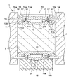
以下、本発明を実施するための最良の形態について図面を用いて説明する。図1は、本実施の形態による分割型転がり軸受ユニットを概略的に示す縦断面図である。 The best mode for carrying out the present invention will be described below with reference to the drawings. FIG. 1 is a longitudinal sectional view schematically showing a split type rolling bearing unit according to the present embodiment.
図1に示すように、分割型の転がり軸受ユニット10は、ロール1のネック部2に固着された内輪11と、ハウジング13と、外輪14と、内輪11の軌道面11aとハウジング13の軌道面13a,外輪14の軌道面14aとの間に単列に所定ピッチで一周分配置された転動体としての複数の円筒ころ12と、を備える。
As shown in FIG. 1, the split type rolling
内輪11の図1のロール1の回転軸p方向の略中心に円筒ころ12が転動自在に位置するようにつば部11b、11b間に軌道面11aが形成され、各つば部11bの回転軸p方向の外側にシール装着部としてシール溝11c、11cが形成されており、シール溝11c、11cに密封装置のシール15,15が嵌め込まれている。内輪11のシール溝11cの更に外側にはシールリング17,17が取り付けられている。
A
ハウジング13の回転軸p方向の左右端にはラビリンスリング16,16が固着されてハウジング13の内径面13bを構成し、その先端16aがロール1の端面に形成された環状溝1a内に延びている。ラビリンスリング16による内径面13bと内輪11側とがシール15によりシールされ、更にシールリング17によりシールされている。
ハウジング13の図1の下方には支持台18が設けられており、支持台18内には、図の破線で示すように、潤滑剤を供給する潤滑剤路18aが形成されている。
A
分割型の転がり軸受ユニット10は、図1のように例えば連続鋳造設備のロール1が小径のネック部2を有する杵型ロールに適用して好ましく、ロール1を両端から離れた位置で更に支持するようにネック部2に取り付けられ、ネック部2がロール1よりも小径であるので、円周方向に分離可能な分割型に構成されている。すなわち、転がり軸受ユニット10の各部品は円周方向に分離した分割部品となっており、図1のネック部2に回転軸p方向に直交する方向から組み込まれた後に、締結ボルト等の締結手段により一体化されるようになっている。このような締結手段は例えば本出願人による上記特許文献1のものを用いることができる。
As shown in FIG. 1, the split type rolling
次に、図1のシール15等による密封装置及び内輪11のシール溝11cについて図2乃至図7を参照して説明する。
Next, a sealing device using the
図2は図1の密封装置のシール15の側断面図である。図3は図2のシール15の正面図である。図4は図3のシール15の要部正面図である。図5は図1の内輪11を図1の一点鎖線A−Aで切断してみた断面図である。図6は図5の内輪の要部断面図である。図7は図2〜図4のシール15を図1のように内輪のシール溝に嵌め込んだときにシールする様子を示す要部断面図である。。
FIG. 2 is a sectional side view of the
図1〜図4に示すように、図1の転がり軸受ユニット10の密封装置は、シール15と、シール15の固定手段としての弾性金属環24と、を備える。シール15は、全体としてリング状に弾性ゴムから構成され、縦断面が略矩形状のシール本体21と、シール本体21から外方に傾めに延びたリップ部22と、を備える。なお、弾性ゴムは耐熱性のものが好ましい。
As shown in FIGS. 1 to 4, the sealing device of the
弾性金属環24は、シール15が内輪11に組み込まれたとき、シール本体21の外周の丸溝23内に位置してシール本体21を円周方向に内輪11側に対し固定するものであり、例えば、鉄鋼等の金属材料からなるコイルスプリングから構成できる。これにより、シール15を内輪11のシール溝11cにおいて円周方向に確実に固定できる。
The
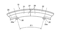
シール15は、図3,図4のように、シール本体21の一箇所に円周方向に分離可能な分割部27を有し、分割部27の近傍に一対の凸部26,26がシール本体21の内周面側に突き出るようにして設けられている。
3 and 4, the
また、シール本体21の内部には鉄鋼等からなる金属ワイヤ25が分割部27を挟んだ周長の短い部分を除いた長い周長側に埋め込まれており、金属ワイヤ25の両端25aが凸部26,26内に入り込んでいる。
In addition, a
シール15が嵌め込まれる内輪11のシール溝11cの底部には、図5,図6のように、シール本体21の内周面に設けられた凸部26,26に対応した位置に凸部26が係合可能な凹部11d、11dが形成されている。シール15が内輪11のシール溝11cに嵌め込まれたとき、シール15の凸部26がシール溝11cの凹部11d内に係合するようになっている。
At the bottom of the
図3,図4のシール15は、分割部27を挟んで凸部26,26間の短い周長側である周長部28が、図5,図6の内輪11のシール溝11cの凹部11d,11d間の短い周長側の周長部29よりも若干長いピッチに設定されている。また、図3〜図6のように、シール15の分割部27を挟んだ凸部26,26間の短い周長側の円弧ピッチ角度θ1がシール溝11cの凹部11d,11d間の短い周長側の円弧ピッチ角度θ2よりも大きく設定されている。
3 and FIG. 4, the
なお、図3のシール15の長い周長側の円弧ピッチ角度θ3は、図5のシール溝11cの長い周長側の円弧ピッチ角度θ4よりも小さくなっている。また、図3の円弧ピッチ角度θ1,θ3の中心cと図5の円弧ピッチ角度θ2,θ4の中心dとは、シール15を内輪11のシール溝11cに嵌め込んだ状態で、ほぼ一致する。
The arc pitch angle θ3 on the long peripheral side of the
上述の分割部27を有するシール15を分割部27で分離した状態で、図1,図7のように、ネック部2に固定された内輪11のシール溝11cに嵌め込み、外輪14やハウジング13等を組み込むことで転がり軸受ユニット10をロール1に取り付けることができる。これにより、図7のように、シール15のシール本体21が内輪11のシール溝11c内に固定され、リップ部22がハウジング13の内径面13bに当接することで、図7の破線で示す初期の状態から実線のように弾性変形して軸受内部10aをシールする。
In the state where the
上述のように、シール15は、分割部27を挟んだ凸部26,26間の短い周長側の周長部28がシール溝11cの凹部11d,11d間の短い周長側の周長部29よりも若干長いピッチに設定されているので、シール本体21の凸部26をシール溝11cの凹部11dに係合させてシール15を内輪11のシール溝11cに嵌め込んだ状態で、短い周長側の周長部28が分割部27を挟んで圧縮方向に僅かに弾性変形する。かかる周長部28の圧縮弾性変形により、分割部27の分割面間に圧縮力が発生する。このようにして分割部27の分割面に圧縮力を発生させることで、分割面は互いに常に圧縮力を受け合うことになるから、分割部27は閉じて隙間を生じない。
As described above, in the
すなわち、シール15のリップ部22は、摺動面(内径面13b)に対し図7のような破線と実線で示される締め代を持ってシール15の密封性を確保するため、リップ部22は摺動面から回転摺動抵抗を受け、分割部27の分割面では回転方向により縮む側と延ばされる側が発生してリップ部22が開こうとしても、上述のように、周長部28における圧縮弾性変形による圧縮力が分割部27の分割面に加わるので、分割面は互いに常に圧縮力を受け合い、分割面は閉じて隙間を生じることがなくなる。
That is, the
したがって、転がり軸受ユニット10の軸受内部10aの内圧が上昇しても、シール15の分割部27に隙間を生じることがなく、分割部27でリップ部22に隙間が生じなく、リップ部22によるシールを維持できるので、転がり軸受ユニット10の軸受内部10aに異物や冷却水の侵入を防ぐことができ、軸受内部10aにおいて錆びを発生させたり、潤滑状態が悪くなることがなくなり、このため、転がり軸受ユニット10の寿命を延ばすことができる。
Therefore, even if the internal pressure of the bearing interior 10a of the
特に、転がり軸受ユニット10が連続鋳造設備のロール1のネック部2に適用され、高温のスラブ等が搬送されて冷却水やスケール等が軸受内部に侵入し易い厳しい使用環境下にある場合でも、冷却水やスケール等の軸受内部10aへの侵入を効果的に防止できる。
In particular, even when the rolling
また、転がり軸受ユニット10の使用中に、ハウジング13の内径面13bに対するシール15のリップ部22の回転摺動抵抗が増大しても、シール本体21の内部には、図2〜図4のように、金属ワイヤ25が長い周長側に埋め込まれているので、シール本体21の延び伸びや縮みが抑制され、シール15の共回りを抑制し、シール溝11cにおけるシール本体21の磨耗を防止できる。このため、シール本体21とシール溝11cとの間の密封性が損なわれることがないので、分割部27を有するシール15の密封性を改良し向上させることができる。
Further, even when the rotational sliding resistance of the
更に、シール本体21の内部の金属ワイヤ25の両端25aがシール本体21から突き出た凸部26,26内に入り込んでいるので、凸部26が金属ワイヤ25で補強され、凸部26が弾性ゴム単体での回転摺動抵抗を受けたことによる欠損とシール15の共回りの発生を防ぐことができる。
Furthermore, since both ends 25a of the
以上のように、シール15の共回りの発生を防ぐことができるので、シール本体21の磨耗を生じることがなく、シール本体21とシール溝11cとの間にも隙間が生じなくなり、これにより、軸受内部10aへのスケール等の異物や冷却水の侵入を防止することができ、錆びを発生させたり、潤滑状態が悪くなることがなくなるので、転がり軸受ユニット10の寿命を延ばすことができる。
As described above, since the occurrence of co-rotation of the
以上のように、本実施の形態によれば、図1〜図7のような密封装置を備えた分割型転がり軸受ユニット10を鉄鋼設備の主として連続鋳造設備の杵型ロールに適用可能であり、シール15の分割部27における密封性を改良することができるとともに、密封性を阻害するシール15の共回りの防止を強化できるので、転がり軸受ユニット10の寿命を延ばすことができる。
As described above, according to the present embodiment, the split type rolling
以上のように本発明を実施するための最良の形態について説明したが、本発明はこれらに限定されるものではなく、本発明の技術的思想の範囲内で各種の変形が可能である。例えば、図1の転がり軸受ユニットは、単列円筒ころ軸受の構造としたが、本発明はこれに限定されず、複列円筒ころ軸受の構造としてもよく、また、図8のような自動調心ころ軸受の構造としてもよい。 As described above, the best mode for carrying out the present invention has been described. However, the present invention is not limited to these, and various modifications are possible within the scope of the technical idea of the present invention. For example, the rolling bearing unit in FIG. 1 has a single-row cylindrical roller bearing structure, but the present invention is not limited to this, and may have a double-row cylindrical roller bearing structure. It is good also as a structure of a center roller bearing.
すなわち、図8の自動調心ころ軸受による分割型転がり軸受ユニット30は、ロール1のネック部2に固着された内輪31と外輪34またはハウジング33との間に保持器35の両側で2列に保持された複数のころ32を転動体として配置したものであり、図1〜図7と同様の密封装置が配置され、同様のシール15が配置されて軸受内部30aをシールしている。転がり軸受ユニット30を鉄鋼設備の主として連続鋳造設備のネック部2を有する杵型のロール1に適用することができ、この場合にシール15の分割部27(図3,図4)における密封性を改良することができ、密封性を阻害するシール15の共回りの防止を強化できるので、転がり軸受ユニット30の寿命を延ばすことができる。
8 is divided into two rows on both sides of the
1 ロール
2 ネック部
10 転がり軸受ユニット
10a 軸受内部
11 内輪
11c シール溝
11d 凹部(被係合部)
12 円筒ころ(転動体)
13 ハウジング(軸箱)
13b 内径面、摺動面
14 外輪
15 シール
21 シール本体
22 リップ部
24 弾性金属環(固定手段)
25 金属ワイヤ(線状または細い板状の金属)
25a 金属ワイヤの両端
26 凸部(係合部)
27 分割部
28 シールの周長部
29 シール溝の周長部
30 転がり軸受ユニット
30a 軸受内部
θ1,θ3 シールの円弧ピッチ角度
θ2,θ4 シール溝の円弧ピッチ角度
DESCRIPTION OF
12 Cylindrical rollers (rolling elements)
13 Housing (shaft box)
13b Inner diameter surface, sliding
25 Metal wire (Linear or thin plate metal)
25a Both ends of
27 Divided
Claims (7)
前記シールは、円周方向に分離可能に一箇所に設けられた分割部と、前記分割部を挟んでかつ前記分割部に近い前記シール本体の内周面に設けられた2つの係合部と、を有し、
前記軸受は、前記各係合部が係合する2つの被係合部を設け前記シール本体を嵌め込むシール溝を内輪に有し、
前記シールの係合部を前記シール溝の被係合部に係合させて前記シールを前記シール溝に嵌め込んだ状態で、前記シールが前記分割部を挟んだ各係合部間の短い周長側で弾性変形して前記分割部の分割面間に圧縮力が加わるように構成され、
前記シールの長い周長側において線状または細い板状の金属が前記シール本体の内部に埋め込まれ、
前記線状または細い板状の金属の両先端が前記係合部に入り込んでいることを特徴とする軸受用密封装置。 A seal having a seal body made of an elastic material and a lip portion that slides on a sliding surface on the outer ring side or the axle box side of the bearing, and fixing for fixing the seal body to the inner ring side of the bearing in the circumferential direction A bearing sealing device comprising:
The seal includes a split portion provided at one place so as to be separable in the circumferential direction, and two engagement portions provided on an inner peripheral surface of the seal body with the split portion interposed therebetween and close to the split portion. Have
The bearing has two engaged portions with which the respective engaging portions are engaged, and has a seal groove in the inner ring into which the seal body is fitted,
With the engagement portion of the seal engaged with the engaged portion of the seal groove and the seal fitted in the seal groove, the seal has a short circumference between the engagement portions sandwiching the divided portion. It is configured such that a compressive force is applied between the split surfaces of the split part by elastically deforming on the long side ,
On the long peripheral side of the seal, a linear or thin plate metal is embedded inside the seal body,
A bearing sealing device, wherein both ends of the linear or thin plate-like metal are inserted into the engaging portion .
前記シールは、円周方向に分離可能に一箇所に設けられた分割部と、前記シールの分割部を挟んでかつ前記分割部に近い前記シール本体の内周面に設けられた2つの係合部と、を有し、
前記軸受は、前記各係合部が係合する2つの被係合部を設け前記シール本体を嵌め込むシール溝を内輪に有し、
前記シールの分割部を挟んだ周長の短い部分以外の長い周長側において線状または細い板状の金属が前記シール本体の内部に埋め込まれ、
前記線状または細い板状の金属の両先端が前記係合部に入り込んでいることを特徴とする軸受用密封装置。 A seal having a seal body made of an elastic material and a lip portion that slides on a sliding surface on the outer ring side or the axle box side of the bearing, and fixing for fixing the seal body to the inner ring side of the bearing in the circumferential direction A bearing sealing device comprising:
The seal has a split portion provided at one place so as to be separable in the circumferential direction, and two engagements provided on the inner peripheral surface of the seal body sandwiching the split portion of the seal and close to the split portion And
The bearing has two engaged portions with which the respective engaging portions are engaged, and has a seal groove in the inner ring into which the seal body is fitted,
On the long peripheral side other than the short peripheral part sandwiching the split part of the seal, a linear or thin plate-like metal is embedded inside the seal body ,
A bearing sealing device, wherein both ends of the linear or thin plate-like metal are inserted into the engaging portion .
Priority Applications (1)
| Application Number | Priority Date | Filing Date | Title |
|---|---|---|---|
| JP2007034540A JP4952284B2 (en) | 2007-02-15 | 2007-02-15 | Bearing sealing device and bearing unit |
Applications Claiming Priority (1)
| Application Number | Priority Date | Filing Date | Title |
|---|---|---|---|
| JP2007034540A JP4952284B2 (en) | 2007-02-15 | 2007-02-15 | Bearing sealing device and bearing unit |
Publications (2)
| Publication Number | Publication Date |
|---|---|
| JP2008196648A JP2008196648A (en) | 2008-08-28 |
| JP4952284B2 true JP4952284B2 (en) | 2012-06-13 |
Family
ID=39755778
Family Applications (1)
| Application Number | Title | Priority Date | Filing Date |
|---|---|---|---|
| JP2007034540A Active JP4952284B2 (en) | 2007-02-15 | 2007-02-15 | Bearing sealing device and bearing unit |
Country Status (1)
| Country | Link |
|---|---|
| JP (1) | JP4952284B2 (en) |
Families Citing this family (1)
| Publication number | Priority date | Publication date | Assignee | Title |
|---|---|---|---|---|
| JP7436345B2 (en) | 2020-10-30 | 2024-02-21 | 株式会社荏原製作所 | Shaft sealing device, rotating machine, and assembly method of shaft sealing device |
Family Cites Families (2)
| Publication number | Priority date | Publication date | Assignee | Title |
|---|---|---|---|---|
| DE2805404A1 (en) * | 1978-02-09 | 1979-08-16 | Merck Patent Gmbh | 1-ARYLOXY-3-NITRATOALKYLAMINO-2-PROPANOLS AND METHOD FOR THE PRODUCTION THEREOF |
| JP4506262B2 (en) * | 2004-04-28 | 2010-07-21 | 日本精工株式会社 | Sealing means for rolling bearing unit Rolling bearing unit |
-
2007
- 2007-02-15 JP JP2007034540A patent/JP4952284B2/en active Active
Also Published As
| Publication number | Publication date |
|---|---|
| JP2008196648A (en) | 2008-08-28 |
Similar Documents
| Publication | Publication Date | Title |
|---|---|---|
| JP4791777B2 (en) | Bearing seal with flexible lip | |
| EP2636915A1 (en) | Vehicle wheel bearing device | |
| JP2008298106A (en) | Wheel bearing device | |
| JP5100056B2 (en) | Wheel bearing device | |
| JP6336768B2 (en) | SEALING DEVICE AND WHEEL BEARING DEVICE HAVING THE SAME | |
| JP2010053893A (en) | Wheel-bearing device | |
| JP5468751B2 (en) | Wheel bearing device | |
| JP2008002487A (en) | Bearing with seal | |
| EP2975279A1 (en) | Bearing device with sealing device | |
| JP2010106925A (en) | Rolling bearing unit | |
| JP6028409B2 (en) | Self-aligning roller bearing with sealing device and manufacturing method thereof | |
| JP4952284B2 (en) | Bearing sealing device and bearing unit | |
| JP5188359B2 (en) | Rolling bearing with seal | |
| JP5468753B2 (en) | Wheel bearing device | |
| JP2007187218A (en) | Bearing device for wheel | |
| JP2017036812A (en) | Wheel bearing device | |
| JP2009144791A (en) | Bearing device for wheel | |
| JP4506262B2 (en) | Sealing means for rolling bearing unit Rolling bearing unit | |
| JP2008082392A (en) | Bearing device for railroad vehicle wheel shaft | |
| JP2005325866A (en) | Bearing for railroad car | |
| KR102525228B1 (en) | Wheel bearing assembly | |
| JP2018100684A (en) | Bearing device for wheel | |
| JP3986775B2 (en) | Railway vehicle bearing unit | |
| JP2017067103A (en) | Bearing device for wheel | |
| CN108026971B (en) | Bearing device for wheel |
Legal Events
| Date | Code | Title | Description |
|---|---|---|---|
| A621 | Written request for application examination |
Free format text: JAPANESE INTERMEDIATE CODE: A621 Effective date: 20100212 |
|
| A977 | Report on retrieval |
Free format text: JAPANESE INTERMEDIATE CODE: A971007 Effective date: 20110922 |
|
| A131 | Notification of reasons for refusal |
Free format text: JAPANESE INTERMEDIATE CODE: A131 Effective date: 20110929 |
|
| A521 | Written amendment |
Free format text: JAPANESE INTERMEDIATE CODE: A523 Effective date: 20111128 |
|
| TRDD | Decision of grant or rejection written | ||
| A01 | Written decision to grant a patent or to grant a registration (utility model) |
Free format text: JAPANESE INTERMEDIATE CODE: A01 Effective date: 20120214 |
|
| A01 | Written decision to grant a patent or to grant a registration (utility model) |
Free format text: JAPANESE INTERMEDIATE CODE: A01 |
|
| A61 | First payment of annual fees (during grant procedure) |
Free format text: JAPANESE INTERMEDIATE CODE: A61 Effective date: 20120227 |
|
| R150 | Certificate of patent or registration of utility model |
Ref document number: 4952284 Country of ref document: JP Free format text: JAPANESE INTERMEDIATE CODE: R150 Free format text: JAPANESE INTERMEDIATE CODE: R150 |
|
| FPAY | Renewal fee payment (event date is renewal date of database) |
Free format text: PAYMENT UNTIL: 20150323 Year of fee payment: 3 |