JP4950079B2 - Optical element including polymer fiber fabric - Google Patents
Optical element including polymer fiber fabric Download PDFInfo
- Publication number
- JP4950079B2 JP4950079B2 JP2007558070A JP2007558070A JP4950079B2 JP 4950079 B2 JP4950079 B2 JP 4950079B2 JP 2007558070 A JP2007558070 A JP 2007558070A JP 2007558070 A JP2007558070 A JP 2007558070A JP 4950079 B2 JP4950079 B2 JP 4950079B2
- Authority
- JP
- Japan
- Prior art keywords
- fibers
- fiber
- polymer
- scattering
- birefringent
- Prior art date
- Legal status (The legal status is an assumption and is not a legal conclusion. Google has not performed a legal analysis and makes no representation as to the accuracy of the status listed.)
- Expired - Fee Related
Links
Images


Classifications
-
- G—PHYSICS
- G02—OPTICS
- G02B—OPTICAL ELEMENTS, SYSTEMS OR APPARATUS
- G02B6/00—Light guides; Structural details of arrangements comprising light guides and other optical elements, e.g. couplings
- G02B6/0001—Light guides; Structural details of arrangements comprising light guides and other optical elements, e.g. couplings specially adapted for lighting devices or systems
- G02B6/0005—Light guides; Structural details of arrangements comprising light guides and other optical elements, e.g. couplings specially adapted for lighting devices or systems the light guides being of the fibre type
- G02B6/001—Light guides; Structural details of arrangements comprising light guides and other optical elements, e.g. couplings specially adapted for lighting devices or systems the light guides being of the fibre type the light being emitted along at least a portion of the lateral surface of the fibre
-
- B—PERFORMING OPERATIONS; TRANSPORTING
- B82—NANOTECHNOLOGY
- B82Y—SPECIFIC USES OR APPLICATIONS OF NANOSTRUCTURES; MEASUREMENT OR ANALYSIS OF NANOSTRUCTURES; MANUFACTURE OR TREATMENT OF NANOSTRUCTURES
- B82Y20/00—Nanooptics, e.g. quantum optics or photonic crystals
-
- G—PHYSICS
- G02—OPTICS
- G02B—OPTICAL ELEMENTS, SYSTEMS OR APPARATUS
- G02B1/00—Optical elements characterised by the material of which they are made; Optical coatings for optical elements
- G02B1/04—Optical elements characterised by the material of which they are made; Optical coatings for optical elements made of organic materials, e.g. plastics
-
- G—PHYSICS
- G02—OPTICS
- G02B—OPTICAL ELEMENTS, SYSTEMS OR APPARATUS
- G02B5/00—Optical elements other than lenses
- G02B5/30—Polarising elements
- G02B5/3008—Polarising elements comprising dielectric particles, e.g. birefringent crystals embedded in a matrix
-
- G—PHYSICS
- G02—OPTICS
- G02B—OPTICAL ELEMENTS, SYSTEMS OR APPARATUS
- G02B5/00—Optical elements other than lenses
- G02B5/30—Polarising elements
- G02B5/3025—Polarisers, i.e. arrangements capable of producing a definite output polarisation state from an unpolarised input state
- G02B5/3033—Polarisers, i.e. arrangements capable of producing a definite output polarisation state from an unpolarised input state in the form of a thin sheet or foil, e.g. Polaroid
-
- G—PHYSICS
- G02—OPTICS
- G02B—OPTICAL ELEMENTS, SYSTEMS OR APPARATUS
- G02B5/00—Optical elements other than lenses
- G02B5/30—Polarising elements
- G02B5/3083—Birefringent or phase retarding elements
-
- G—PHYSICS
- G02—OPTICS
- G02B—OPTICAL ELEMENTS, SYSTEMS OR APPARATUS
- G02B6/00—Light guides; Structural details of arrangements comprising light guides and other optical elements, e.g. couplings
- G02B6/0001—Light guides; Structural details of arrangements comprising light guides and other optical elements, e.g. couplings specially adapted for lighting devices or systems
- G02B6/0011—Light guides; Structural details of arrangements comprising light guides and other optical elements, e.g. couplings specially adapted for lighting devices or systems the light guides being planar or of plate-like form
- G02B6/0033—Means for improving the coupling-out of light from the light guide
- G02B6/005—Means for improving the coupling-out of light from the light guide provided by one optical element, or plurality thereof, placed on the light output side of the light guide
- G02B6/0051—Diffusing sheet or layer
-
- G—PHYSICS
- G02—OPTICS
- G02B—OPTICAL ELEMENTS, SYSTEMS OR APPARATUS
- G02B6/00—Light guides; Structural details of arrangements comprising light guides and other optical elements, e.g. couplings
- G02B6/0001—Light guides; Structural details of arrangements comprising light guides and other optical elements, e.g. couplings specially adapted for lighting devices or systems
- G02B6/0011—Light guides; Structural details of arrangements comprising light guides and other optical elements, e.g. couplings specially adapted for lighting devices or systems the light guides being planar or of plate-like form
- G02B6/0033—Means for improving the coupling-out of light from the light guide
- G02B6/005—Means for improving the coupling-out of light from the light guide provided by one optical element, or plurality thereof, placed on the light output side of the light guide
- G02B6/0053—Prismatic sheet or layer; Brightness enhancement element, sheet or layer
-
- G—PHYSICS
- G02—OPTICS
- G02B—OPTICAL ELEMENTS, SYSTEMS OR APPARATUS
- G02B6/00—Light guides; Structural details of arrangements comprising light guides and other optical elements, e.g. couplings
- G02B6/04—Light guides; Structural details of arrangements comprising light guides and other optical elements, e.g. couplings formed by bundles of fibres
-
- G—PHYSICS
- G02—OPTICS
- G02B—OPTICAL ELEMENTS, SYSTEMS OR APPARATUS
- G02B6/00—Light guides; Structural details of arrangements comprising light guides and other optical elements, e.g. couplings
- G02B6/10—Light guides; Structural details of arrangements comprising light guides and other optical elements, e.g. couplings of the optical waveguide type
- G02B6/105—Light guides; Structural details of arrangements comprising light guides and other optical elements, e.g. couplings of the optical waveguide type having optical polarisation effects
-
- Y—GENERAL TAGGING OF NEW TECHNOLOGICAL DEVELOPMENTS; GENERAL TAGGING OF CROSS-SECTIONAL TECHNOLOGIES SPANNING OVER SEVERAL SECTIONS OF THE IPC; TECHNICAL SUBJECTS COVERED BY FORMER USPC CROSS-REFERENCE ART COLLECTIONS [XRACs] AND DIGESTS
- Y10—TECHNICAL SUBJECTS COVERED BY FORMER USPC
- Y10T—TECHNICAL SUBJECTS COVERED BY FORMER US CLASSIFICATION
- Y10T428/00—Stock material or miscellaneous articles
- Y10T428/29—Coated or structually defined flake, particle, cell, strand, strand portion, rod, filament, macroscopic fiber or mass thereof
- Y10T428/2913—Rod, strand, filament or fiber
- Y10T428/2933—Coated or with bond, impregnation or core
- Y10T428/2964—Artificial fiber or filament
- Y10T428/2967—Synthetic resin or polymer
-
- Y—GENERAL TAGGING OF NEW TECHNOLOGICAL DEVELOPMENTS; GENERAL TAGGING OF CROSS-SECTIONAL TECHNOLOGIES SPANNING OVER SEVERAL SECTIONS OF THE IPC; TECHNICAL SUBJECTS COVERED BY FORMER USPC CROSS-REFERENCE ART COLLECTIONS [XRACs] AND DIGESTS
- Y10—TECHNICAL SUBJECTS COVERED BY FORMER USPC
- Y10T—TECHNICAL SUBJECTS COVERED BY FORMER US CLASSIFICATION
- Y10T428/00—Stock material or miscellaneous articles
- Y10T428/29—Coated or structually defined flake, particle, cell, strand, strand portion, rod, filament, macroscopic fiber or mass thereof
- Y10T428/2913—Rod, strand, filament or fiber
- Y10T428/2973—Particular cross section
-
- Y—GENERAL TAGGING OF NEW TECHNOLOGICAL DEVELOPMENTS; GENERAL TAGGING OF CROSS-SECTIONAL TECHNOLOGIES SPANNING OVER SEVERAL SECTIONS OF THE IPC; TECHNICAL SUBJECTS COVERED BY FORMER USPC CROSS-REFERENCE ART COLLECTIONS [XRACs] AND DIGESTS
- Y10—TECHNICAL SUBJECTS COVERED BY FORMER USPC
- Y10T—TECHNICAL SUBJECTS COVERED BY FORMER US CLASSIFICATION
- Y10T442/00—Fabric [woven, knitted, or nonwoven textile or cloth, etc.]
- Y10T442/20—Coated or impregnated woven, knit, or nonwoven fabric which is not [a] associated with another preformed layer or fiber layer or, [b] with respect to woven and knit, characterized, respectively, by a particular or differential weave or knit, wherein the coating or impregnation is neither a foamed material nor a free metal or alloy layer
-
- Y—GENERAL TAGGING OF NEW TECHNOLOGICAL DEVELOPMENTS; GENERAL TAGGING OF CROSS-SECTIONAL TECHNOLOGIES SPANNING OVER SEVERAL SECTIONS OF THE IPC; TECHNICAL SUBJECTS COVERED BY FORMER USPC CROSS-REFERENCE ART COLLECTIONS [XRACs] AND DIGESTS
- Y10—TECHNICAL SUBJECTS COVERED BY FORMER USPC
- Y10T—TECHNICAL SUBJECTS COVERED BY FORMER US CLASSIFICATION
- Y10T442/00—Fabric [woven, knitted, or nonwoven textile or cloth, etc.]
- Y10T442/30—Woven fabric [i.e., woven strand or strip material]
- Y10T442/3065—Including strand which is of specific structural definition
Abstract
Description
本発明は、ポリマー光学素子に関し、特に、ポリマー繊維を含む織物を含むポリマー光学素子に関する。 The present invention relates to a polymer optical element, and more particularly to a polymer optical element including a fabric including polymer fibers.
非偏光波は、光ビームの軸の周りの多数の平面内で振動する。波が1つの平面内でのみ振動する場合、光は、平面偏光されるといわれる。いくつかの有用な光学システムを、偏光を使用して実現することができる。たとえば、液晶ディスプレイスクリーンなどの電気光学デバイスが、偏光で照明され、かつ、画像形成を表示するための基礎を提供するために、アドレス可能な液晶中間層と関連して、交差した偏光子を使用する。写真の分野において、偏光フィルタが、グレアおよび正反射の輝度を低減するために使用されている。偏光フィルタ、円偏光子、または他の光学構成要素が、また、ディスプレイデバイススクリーンにおけるグレア低減のために使用されている。 Unpolarized waves oscillate in a number of planes around the axis of the light beam. If the wave vibrates only in one plane, the light is said to be plane polarized. Some useful optical systems can be realized using polarized light. For example, an electro-optic device such as a liquid crystal display screen is illuminated with polarized light and uses crossed polarizers in conjunction with an addressable liquid crystal interlayer to provide a basis for displaying image formation To do. In the field of photography, polarizing filters are used to reduce the brightness of glare and specular reflection. Polarization filters, circular polarizers, or other optical components have also been used for glare reduction in display device screens.
いくつかの異なる種類の偏光フィルムが、非偏光を偏光するために入手可能である。吸収(二色性)偏光子が、含有(inclusion)相として、ポリマーマトリックス内で整列された偏光依存吸収種、しばしばヨウ素含有鎖を有する。そのようなフィルムは、電界ベクトルが吸収種に平行に整列された状態で偏光された光を吸収し、吸収種に垂直に偏光された光を透過する。そのようなフィルムの光学特性は、典型的には正反射性であり、フィルムを通る拡散透過、またはフィルム表面からの拡散反射が、ほとんどない。 Several different types of polarizing films are available for polarizing unpolarized light. Absorbing (dichroic) polarizers have polarization-dependent absorbing species, often iodine-containing chains, aligned within the polymer matrix as the inclusion phase. Such films absorb light polarized with the electric field vector aligned parallel to the absorbing species and transmit light polarized perpendicular to the absorbing species. The optical properties of such films are typically specular, with little diffuse transmission through the film or diffuse reflection from the film surface.
別のタイプの偏光フィルムが、一方の状態の光を透過し、他方の状態の光を反射することによって、異なる偏光状態の光を分ける反射偏光子である。1つのタイプの反射偏光子が、多層光学フィルム(MOF)であり、これは、交互のポリマー材料の多くの層のスタックから形成されたフィルムである。材料の1つが光学的に等方性であり、他方が複屈折性であり、その屈折率の1つが等方性材料の屈折率に整合する。層厚さは、広範囲の波長にわたって、たとえば可視領域にわたって4分の1波長層であるように、スタック全体にわたって変えることができる。1つの偏光状態で入射する光が、整合した屈折率を示し、偏光子を実質的に正透過される。しかし、他方の偏光状態で入射する光が、異なる層の間の界面で多数の干渉または非干渉反射を示し、偏光子によって反射される。交互のポリマー層が実質的に平面であるので、反射光はほとんど正反射される。 Another type of polarizing film is a reflective polarizer that separates light in different polarization states by transmitting light in one state and reflecting light in the other state. One type of reflective polarizer is a multilayer optical film (MOF), which is a film formed from a stack of many layers of alternating polymer material. One of the materials is optically isotropic, the other is birefringent, and one of its refractive indices matches the refractive index of the isotropic material. The layer thickness can vary across the stack to be a quarter wave layer over a wide range of wavelengths, for example over the visible region. Light incident in one polarization state exhibits a matched refractive index and is substantially specularly transmitted through the polarizer. However, light incident in the other polarization state exhibits multiple interference or incoherent reflections at the interface between the different layers and is reflected by the polarizer. Since the alternating polymer layers are substantially planar, the reflected light is almost specularly reflected.
別のタイプの反射偏光フィルムが、連続相マトリックス内に分散された含有物(inclusions)から構成される。含有物は、フィルムの幅および高さに対して小さい。これらの含有物の特徴は、ある範囲の反射特性および透過特性をフィルムに与えるように操作することができる。含有物は、連続相マトリックス内の分散ポリマー相を構成する。含有物サイズおよび整列は、フィルムを延伸することによって変更することができる。連続相または分散相が複屈折性であり、複屈折性材料の屈折率の1つが、光学的に等方性である他方の相の屈折率に整合する。延伸の程度とともに、連続相および分散相のための材料の選択が、分散相と連続相との間の複屈折屈折率不整合(birefringent refractive index mismatch)の程度に影響を及ぼすことができる。調整することができる他の特徴としては、フィルム内の波長に対する含有物サイズ、含有物形状、および含有物体積充填率が挙げられる。そのようなシステムにおいて、分散相と連続相との間の屈折率不整合を示すように偏光された光が拡散反射され、直交偏光が正透過される。 Another type of reflective polarizing film is comprised of inclusions dispersed within a continuous phase matrix. Inclusions are small relative to the width and height of the film. The characteristics of these inclusions can be manipulated to give the film a range of reflective and transmissive properties. The inclusions constitute the dispersed polymer phase within the continuous phase matrix. Inclusion size and alignment can be changed by stretching the film. The continuous phase or dispersed phase is birefringent, and one of the refractive indices of the birefringent material matches the refractive index of the other phase, which is optically isotropic. Along with the degree of stretching, the selection of materials for the continuous and dispersed phases can affect the degree of birefringent refractive index mismatch between the dispersed and continuous phases. Other features that can be adjusted include inclusion size, inclusion shape, and inclusion volume fill for wavelength within the film. In such a system, light polarized so as to exhibit a refractive index mismatch between the disperse phase and the continuous phase is diffusely reflected and orthogonally polarized light is specularly transmitted.
本発明の1つの特定の実施形態が、マトリックスポリマー材料を含むポリマーマトリックスと、ポリマーマトリックス内に配置された少なくとも1つの繊維織物とを含む光学体に関する。繊維織物は複数のポリマー繊維を含み、ポリマー繊維は第1のポリマー繊維材料と、第2のポリマー繊維材料とを含む。マトリックスポリマー材料、第1の繊維ポリマー材料、および第2の繊維ポリマー材料の少なくとも1つが、複屈折性である。 One particular embodiment of the present invention relates to an optical body comprising a polymer matrix comprising a matrix polymer material and at least one fiber fabric disposed within the polymer matrix. The fiber fabric includes a plurality of polymer fibers, and the polymer fibers include a first polymer fiber material and a second polymer fiber material. At least one of the matrix polymer material, the first fiber polymer material, and the second fiber polymer material is birefringent.
本発明の上記概要は、本発明の各々の例示された実施形態またはあらゆる実装形態を説明することは意図されていない。次の図および詳細な説明は、これらの実施形態をより詳細に例示する。 The above summary of the present invention is not intended to describe each illustrated embodiment or every implementation of the present invention. The following figures and detailed description illustrate these embodiments in more detail.
本発明は、添付の図面とともに、本発明のさまざまな実施形態の次の詳細な説明を考慮して、より完全に理解することができる。 The invention may be more fully understood in view of the following detailed description of various embodiments of the invention in conjunction with the accompanying drawings.
本発明は、さまざまな変更例および代替形態が可能であるが、その特定のものが、図面に例として示されており、詳細に説明される。しかし、本発明を、説明される特定の実施形態に限定することは意図されていないことが理解されるべきである。それどころか、添付の特許請求の範囲によって規定されるような本発明の趣旨および範囲内である変更例、均等物、および代替例をすべて包含することが意図される。 While the invention is susceptible to various modifications and alternative forms, specifics thereof are shown by way of example in the drawings and will be described in detail. It should be understood, however, that the intention is not to limit the invention to the particular embodiments described. On the contrary, the intention is to cover all modifications, equivalents, and alternatives falling within the spirit and scope of the invention as defined by the appended claims.
本発明は、光学システムに適用でき、特に、偏光光学システムに適用できる。 The present invention can be applied to an optical system, and in particular to a polarizing optical system.
本明細書で使用されるように、「正反射(specular reflection)」および「正反射(specular reflectance)」という用語は、反射角が入射角に実質的に等しい、本体からの光線の反射を指し、角度は、本体の表面に対する法線に対して測定される。換言すれば、光が特定の角度分布で本体に入射するとき、反射光は実質的に同じ角度分布を有する。「拡散反射(diffuse reflection)」または「拡散反射(diffuse reflectance)」という用語は、反射光のいくらかの角度が入射角に等しくない、光線の反射を指す。したがって、光が特定の角度分布で本体に入射するとき、反射光の角度分布は入射光の角度分布と異なる。「全反射(total reflectance)」または「全反射(total reflection)」という用語は、正反射および拡散の、すべての光の組合された反射を指す。 As used herein, the terms “specular reflection” and “specular reflection” refer to the reflection of light rays from the body, where the reflection angle is substantially equal to the angle of incidence. The angle is measured relative to the normal to the surface of the body. In other words, when light enters the body with a specific angular distribution, the reflected light has substantially the same angular distribution. The term “diffuse reflection” or “diffuse reflection” refers to the reflection of light rays where some angle of the reflected light is not equal to the angle of incidence. Therefore, when light enters the main body with a specific angular distribution, the angular distribution of reflected light is different from the angular distribution of incident light. The term “total reflection” or “total reflection” refers to the combined reflection of all light, specular and diffuse.
同様に、「正透過(specular transmission)」および「正透過(specular transmittance)」という用語は、透過光の角度分布が入射光の角度分布と実質的に同じである、本体を通る光の透過に関して、本明細書で使用される。「拡散透過(diffuse transmission)」および「拡散透過(diffuse transmittance)」という用語は、透過光が、入射光の角度分布と異なる角度分布を有する、本体を通る光の透過を説明するために使用される。「全透過(total transmission)」または「全透過(total transmittance)」という用語は、正および拡散の、すべての光の組合された透過を指す。 Similarly, the terms “specular transmission” and “specular transmission” refer to the transmission of light through the body, where the angular distribution of transmitted light is substantially the same as the angular distribution of incident light. As used herein. The terms “diffuse transmission” and “diffuse transmission” are used to describe the transmission of light through the body, where the transmitted light has an angular distribution that differs from the angular distribution of the incident light. The The term “total transmission” or “total transmission” refers to the combined transmission of all light, positive and diffuse.
フィルムの形態の反射偏光子100が、図1Aおよび図1Bに概略的に示されている。ここで採用される慣行において、フィルムの厚さ方向はz軸とみなされ、x−y平面はフィルムの平面に平行である。非偏光102が偏光子100に入射すると、偏光子100の透過軸に平行に偏光された光104は透過され、偏光子100の反射軸に平行に偏光された光106は反射される。反射光の角度分布は、偏光子100のさまざまな特徴に依存する。たとえば、いくつかの例示的な実施形態において、図1Aに概略的に示されているように、光106を正反射することができ、他の実施形態において、図1Bに概略的に示されているように、光106を拡散反射することができる。他の実施形態において、反射光は、正成分および拡散成分の両方を含むことができる。示された実施形態において、偏光子の透過軸はx軸に平行であり、偏光子100の反射軸はy軸に平行である。他の実施形態において、これらを逆にすることができる。透過光104は、正透過するか、拡散透過するか、正成分および拡散成分の組合せで透過することができる。
A
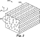
本発明の例示的な実施形態による反射偏光子本体を通る破断図が、図2に概略的に示されている。光学体200は、連続相とも呼ばれるポリマーマトリックス202を含む。ポリマーマトリックスは、光学的に等方性または光学的に複屈折性であることができる。たとえば、ポリマーマトリックスは、一軸または二軸複屈折性であることができ、ポリマーの屈折率が、1つの方向に沿って異なり、2つの直交する方向において同様であることができる(一軸)か、3つの直交する方向すべてにおいて異なることができる(二軸)ことを意味する。
A cutaway view through a reflective polarizer body according to an exemplary embodiment of the present invention is schematically illustrated in FIG. The
ポリマー繊維204がマトリックス202内に配置される。ポリマー繊維204は、少なくとも2つの材料を含む。いくつかの例示的な実施形態において、材料の1つが複屈折性であり、1つまたは複数の他の材料が等方性である。他の実施形態において、繊維を形成する材料の2つ以上が複屈折性である。また、いくつかの他の実施形態において、繊維を形成する材料は等方性であることができる。他の実施形態において、等方性ポリマー繊維204および複屈折性ポリマー繊維204の両方をマトリックス202内に配置することができる。
ポリマー繊維204は、示されているように1つの繊維として、または多くの他の配列で、マトリックス202内に組織化することができる。いくつかの例示的な配列としては、ヤーン、ポリマーマトリックス内に1つの方向に配列されたトウ(繊維またはヤーンの)、織物、不織布、チョップドファイバー、チョップドファイバーマット(ランダムなまたは整ったフォーマットを有する)、またはこれらのフォーマットの組合せが挙げられる。チョップドファイバーマットまたは不織布は、繊維のランダムな配列を有するのではなく、不織布またはチョップドファイバーマット内の繊維のいくらかの整列をもたらすために、延伸するか、応力を加えるか、配向することができる。
The
第1の繊維材料の、x、y、およびz方向の屈折率は、n1x、n1y、およびn1zと呼ぶことができ、第2の繊維材料の、x、y、およびz方向の屈折率は、n2x、n2y、およびn2zと呼ぶことができる。材料が等方性である場合、x、y、およびz屈折率は、すべて実質的に整合する。第1の繊維材料が複屈折性である場合、x、y、およびz屈折率の少なくとも1つが、他のものと異なる。 The refractive index of the first fiber material in the x, y, and z directions can be referred to as n 1x , n 1y , and n 1z , and the refraction in the x, y, and z directions of the second fiber material. The rates can be referred to as n 2x , n 2y , and n 2z . If the material is isotropic, the x, y, and z refractive indices are all substantially matched. When the first fiber material is birefringent, at least one of the x, y, and z refractive indices is different from the others.
各繊維204内に、第1の繊維材料と第2の繊維材料との間に、多数の界面がある。界面を形成する材料の少なくとも1つが複屈折性である場合、界面は複屈折性界面と呼ばれる。たとえば、2つの材料が、界面において、それらのxおよびy屈折率を示し、n1x≠n1y、すなわち、第1の材料が複屈折性である場合、界面は複屈折性である。複屈折性界面を含むポリマー繊維の異なる例示的な実施形態を、以下で説明する。
Within each
繊維204は、図にx軸として示された軸に略平行に配置される。x軸に平行に偏光された光の、繊維204内の複屈折性界面における屈折率差n1x−n2xは、y軸に平行に偏光された光の屈折率差n1y−n2yと異なることができる。したがって、1つの偏光状態について、繊維204内の複屈折性界面における屈折率差は比較的小さいことができる。いくつかの例示的な場合において、屈折率差は、0.05未満であることができる。この状態は、実質的に屈折率が整合したと考えられる。この屈折率差は、0.03未満、0.02未満、または0.01未満であることができる。この偏光方向がx軸に平行である場合、x偏光が、本体200を通過し、反射がほとんどまたはまったくない。換言すれば、x偏光は、本体200を高度に透過される。
The
繊維内の複屈折性界面における屈折率差は、直交偏光状態の光について、比較的高いことができる。いくつかの例示的な例において、屈折率差は、少なくとも0.05であることができ、より大きい、たとえば0.1、または0.15であることができるか、0.2であることができる。この偏光方向がy軸に平行である場合、y偏光が、複屈折性界面において反射される。したがって、y偏光は本体200によって反射される。繊維204内の複屈折性界面が、互いに実質的に平行である場合、反射は本質的に正反射であることができる。一方、繊維204内の複屈折性界面が、互いに実質的に平行でない場合、反射は実質的に拡散であることができる。複屈折性界面のいくつかが平行であることができ、他の界面が非平行であることができ、これは、正成分および拡散成分の両方を含む反射光をもたらすことができる。また、複屈折性界面が、湾曲しているか、比較的小さい、換言すれば、入射光の波長の1桁以内であることができ、これは、拡散散乱をもたらすことができる。
The refractive index difference at the birefringent interface in the fiber can be relatively high for light in the orthogonal polarization state. In some illustrative examples, the refractive index difference can be at least 0.05, and can be larger, for example, 0.1, or 0.15, or 0.2. it can. When this polarization direction is parallel to the y-axis, y-polarized light is reflected at the birefringent interface. Therefore, y-polarized light is reflected by the
すぐ上で説明された例示的な実施形態は、y方向の比較的大きい屈折率差を伴うx方向の屈折率整合に関するが、他の例示的な実施形態が、x方向の比較的大きい屈折率差を伴うy方向の屈折率整合を含む。 The exemplary embodiment described immediately above relates to refractive index matching in the x direction with a relatively large refractive index difference in the y direction, while other exemplary embodiments have a relatively large refractive index in the x direction. Includes index matching in the y direction with differences.
ポリマーマトリックス202は、実質的に光学的に等方性であることができ、たとえば、約0.05未満、好ましくは0.01未満の複屈折n3x−n3yを有することができ、ここで、xおよびy方向のマトリックスの屈折率は、それぞれ、n3xおよびn3yである。他の実施形態において、ポリマーマトリックス202は複屈折性であることができる。したがって、いくつかの実施形態において、ポリマーマトリックスと繊維材料との間の屈折率差は、異なる方向において異なることができる。たとえば、x屈折率差n1x−n3xは、y屈折率差n1y−n3yと異なることができる。いくつかの実施形態において、これらの屈折率差の1つが、他方の屈折率差の少なくとも2倍も大きいことができる。
The
いくつかの実施形態において、屈折率差、複屈折性界面の広さおよび形状、ならびに複屈折性界面の相対位置は、入射偏光の1つの、他方の偏光より大きい拡散散乱をもたらすことができる。そのような散乱は、主として後方散乱(拡散反射)前方散乱(拡散透過)または後方散乱および前方散乱の両方の組合せであることができる。 In some embodiments, the refractive index difference, the width and shape of the birefringent interface, and the relative position of the birefringent interface can result in more diffuse scattering of one of the incident polarizations than the other polarization. Such scattering can be primarily backscattering (diffuse reflection) forward scattering (diffuse transmission) or a combination of both backscattering and forward scattering.
ポリマーマトリックスおよび/または繊維での使用のための適切な材料としては、光波長の所望の範囲にわたって透明である熱可塑性および熱硬化性ポリマーが挙げられる。いくつかの実施形態において、ポリマーが水に不溶性であることが特に有用であり得る。さらに、適切なポリマー材料が、アモルファスまたは半結晶性であることができ、ホモポリマー、コポリマー、またはそれらのブレンドを含むことができる。ポリマー材料例としては、ポリ(カーボネート)(PC);シンジオタクチックおよびイソタクチックポリ(スチレン)(PS);C1−C8アルキルスチレン;ポリ(メチルメタクリレート)(PMMA)およびPMMAコポリマーを含む、アルキル、芳香族、および脂肪族環含有(メタ)アクリレート;エトキシ化およびプロポキシ化(メタ)アクリレート;多官能性(メタ)アクリレート;アクリレート化エポキシ;エポキシ;ならびに他のエチレン不飽和材料;環状オレフィンおよび環状オレフィンコポリマー;アクリロニトリルブタジエンスチレン(ABS);スチレンアクリロニトリルコポリマー(SAN);エポキシ;ポリ(ビニルシクロヘキサン);PMMA/ポリ(フッ化ビニル)ブレンド;ポリ(フェニレンオキシド)合金;スチレンブロックコポリマー;ポリイミド;ポリスルホン;ポリ(塩化ビニル);ポリ(ジメチルシロキサン)(PDMS);ポリウレタン;不飽和ポリエステル;低複屈折ポリエチレンを含むポリ(エチレン);ポリ(プロピレン)(PP);ポリ(エチレンテレフタレート)(PET)などのポリ(アルカンテレフタレート);ポリ(エチレンナフタレート)(PEN)などのポリ(アルカンナフタレート);ポリアミド;イオノマー;酢酸ビニル/ポリエチレンコポリマー;セルロースアセテート;セルロースアセテートブチレート;フルオロポリマー;ポリ(スチレン)−ポリ(エチレン)コポリマー;ポリオレフィンPETおよびPENを含むPETおよびPENコポリマー;ならびにポリ(カーボネート)/脂肪族PETブレンドが挙げられるが、これらに限定されない。(メタ)アクリレートという用語は、対応するメタクリレート化合物またはアクリレート化合物であると定義する。シンジオタクチックPSを除いて、これらのポリマーは、光学的に等方性の形態で使用することができる。 Suitable materials for use in the polymer matrix and / or fiber include thermoplastic and thermosetting polymers that are transparent over the desired range of light wavelengths. In some embodiments, it can be particularly useful that the polymer is insoluble in water. In addition, suitable polymeric materials can be amorphous or semi-crystalline and can include homopolymers, copolymers, or blends thereof. Examples of polymeric materials include poly (carbonate) (PC); syndiotactic and isotactic poly (styrene) (PS); C1-C8 alkyl styrene; poly (methyl methacrylate) (PMMA) and alkyls including PMMA copolymers , Aromatic, and aliphatic ring-containing (meth) acrylates; ethoxylated and propoxylated (meth) acrylates; multifunctional (meth) acrylates; acrylated epoxies; epoxies; and other ethylenically unsaturated materials; Olefin copolymer; Acrylonitrile butadiene styrene (ABS); Styrene acrylonitrile copolymer (SAN); Epoxy; Poly (vinylcyclohexane); PMMA / poly (vinyl fluoride) blend; Poly (phenylene oxide) Polystyrene; Polysulfone; Poly (vinyl chloride); Poly (dimethylsiloxane) (PDMS); Polyurethane; Unsaturated polyester; Poly (ethylene) including low birefringence polyethylene; Poly (propylene) (PP); Poly (alkane terephthalate) such as poly (ethylene terephthalate) (PET); Poly (alkane naphthalate) such as poly (ethylene naphthalate) (PEN); Polyamide; Ionomer; Vinyl acetate / polyethylene copolymer; Cellulose acetate; Fluoropolymer; poly (styrene) -poly (ethylene) copolymer; PET and PEN copolymers including polyolefin PET and PEN; and poly (carbonate) / aliphatic PET Rend including but not limited to. The term (meth) acrylate is defined as the corresponding methacrylate compound or acrylate compound. With the exception of syndiotactic PS, these polymers can be used in an optically isotropic form.
これらのポリマーのいくつかが、配向されると、複屈折性になることができる。特に、PET、PEN、およびそれらのコポリマー、ならびに液晶ポリマーが、配向されると、比較的大きい複屈折値を明示する。ポリマーを、押出および延伸を含む異なる方法を用いて配向することができる。延伸は、ポリマーを配向するための特に有用な方法であり、というのは、それは、高配向度を可能にし、温度および延伸比などの、いくつかの容易に制御可能な外部パラメータによって制御することができるからである。配向されたおよび配向されていない、いくつかの例示的なポリマーの屈折率が、下記表Iに提供される。 Some of these polymers can become birefringent when oriented. In particular, PET, PEN, and their copolymers, as well as liquid crystal polymers, exhibit relatively large birefringence values when oriented. The polymer can be oriented using different methods including extrusion and stretching. Stretching is a particularly useful method for orienting polymers because it allows for a high degree of orientation and is controlled by several easily controllable external parameters such as temperature and stretch ratio. Because you can. The refractive indices of some exemplary polymers, oriented and unoriented, are provided in Table I below.

PCTGおよびPETG(グリコール変性ポリエチレンテレフタレート)は、たとえば、テネシー州キングズポートのイーストマン・ケミカル・カンパニー(Eastman Chemical Co.,Kingsport,TN)からイースター(Eastar)(登録商標)ブランド名で入手可能なコポリエステルのタイプである。THVは、ミネソタ州セントポールの3Mカンパニー(3M Company,St.Paul,MN)からブランド名ダイニオン(Dyneon)(登録商標)で入手可能な、テトラフルオロエチレン、ヘキサフルオロプロピレン、およびフッ化ビニリデンのポリマーである。PS/PMMAコポリマーは、所望の屈折率値を達成するために、コポリマー中の成分モノマーの比を変化させることによって屈折率を「調整する」ことができるコポリマーの例である。「S.R.」と標記された列は延伸比を含む。1の延伸比が、材料が、延伸されておらず、配向されていないことを意味する。6の延伸比が、サンプルが、その元の長さの6倍に延伸されたことを意味する。正しい温度条件下で延伸される場合、ポリマー分子は配向され、材料は複屈折性になる。しかし、分子を配向することなく、材料を延伸することが可能である。「T」と標記された列は、サンプルが延伸された温度を示す。延伸されたサンプルは、シートとして延伸された。nx、ny、およびnzと標記された列は、材料の屈折率に言及する。nyおよびnzについて表に値が記載されていない場合、nyおよびnzの値はnxと同じである。 PCTG and PETG (glycol-modified polyethylene terephthalate) are available from, for example, the Eastar® brand name from Eastman Chemical Co., Kingsport, TN, Kingsport, Tennessee. Polyester type. THV is a polymer of tetrafluoroethylene, hexafluoropropylene, and vinylidene fluoride available under the brand name Dyneon® from 3M Company, St. Paul, Minnesota (3M Company, St. Paul, MN). It is. PS / PMMA copolymers are examples of copolymers whose refractive index can be “tuned” by changing the ratio of component monomers in the copolymer to achieve the desired refractive index value. The column labeled “SR” contains the stretch ratio. A stretch ratio of 1 means that the material is not stretched and not oriented. A stretch ratio of 6 means that the sample was stretched 6 times its original length. When stretched under the correct temperature conditions, the polymer molecules are oriented and the material becomes birefringent. However, it is possible to stretch the material without orienting the molecules. The column labeled “T” indicates the temperature at which the sample was stretched. The stretched sample was stretched as a sheet. n x, n y, and n z as the title column refers to the refractive index of the material. If the n y and n z are not listed values in the table, the value of n y and n z are the same as n x.
繊維の延伸下での屈折率の挙動は、シートを延伸する場合の結果と同様であるが必ずしも同じでない結果を与えることが予期される。ポリマー繊維を、所望の屈折率値を生じさせる任意の所望の値に延伸することができる。たとえば、いくつかのポリマー繊維が、少なくとも3の延伸比を生じさせるように延伸することができ、少なくとも6であることができる。いくつかの実施形態において、ポリマー繊維を、さらに、たとえば20までの延伸比に、またはさらに延伸することができる。 It is expected that the refractive index behavior under fiber stretching will give results that are similar to, but not necessarily the same as when the sheet is stretched. The polymer fibers can be drawn to any desired value that yields the desired refractive index value. For example, some polymer fibers can be drawn to produce a draw ratio of at least 3, and can be at least 6. In some embodiments, the polymer fibers can be further drawn, for example, to a draw ratio of up to 20, or further.
複屈折を達成するための延伸のための適切な温度が、ケルビンで表現されたポリマー融点の約80%である。複屈折を、また、押出およびフィルム形成プロセスの間に生じるポリマー溶融物の流れによって誘起される応力によって誘起することができる。複屈折を、また、フィルム物品内の繊維などの隣接した表面との整列によって生じさせることができる。複屈折は正または負であることができる。正の複屈折は、直線偏光の電界軸の方向が、ポリマーの配向または整列表面に平行である場合に最高屈折率になる場合と定義する。負の複屈折は、直線偏光の電界軸の方向が、ポリマーの配向または整列表面に平行である場合に最低屈折率になる場合と定義する。正の複屈折性のポリマーの例としては、PENおよびPETが挙げられる。負の複屈折性のポリマーの例としては、シンジオタクチックポリスチレンが挙げられる。 A suitable temperature for stretching to achieve birefringence is about 80% of the polymer melting point expressed in Kelvin. Birefringence can also be induced by stresses induced by the polymer melt flow that occurs during the extrusion and film forming processes. Birefringence can also be caused by alignment with adjacent surfaces such as fibers in the film article. Birefringence can be positive or negative. Positive birefringence is defined as the highest refractive index when the direction of the linearly polarized electric field axis is parallel to the polymer orientation or alignment surface. Negative birefringence is defined as the case where the direction of the electric field axis of linearly polarized light has the lowest refractive index when it is parallel to the polymer orientation or alignment surface. Examples of positive birefringent polymers include PEN and PET. An example of a negative birefringent polymer is syndiotactic polystyrene.
所望の特性を光学体200に与えるために、マトリックス202および/またはポリマー繊維204に、さまざまな添加剤を提供することができる。たとえば、添加剤は、次のもの、すなわち、耐候剤、UV吸収剤、ヒンダードアミン光安定剤、酸化防止剤、分散剤、潤滑剤、帯電防止剤、顔料または染料、造核剤、難燃剤、および発泡剤の1つ以上を含むことができる。ポリマーの屈折率を変更するか、材料の強度を増加させるための他の添加剤を提供することができる。そのような添加剤としては、たとえば、ポリマービーズもしくはポリマー粒子およびポリマーナノ粒子などの有機添加剤、または、ガラス、セラミック、もしくは金属酸化物ナノ粒子、または、粉砕物、粉末、ビーズ、フレーク、もしくは微粒子ガラス、セラミック、もしくはガラスセラミックなどの無機添加剤を挙げることができる。これらの添加剤の表面に、ポリマーに結合するための結合剤を提供することができる。たとえば、シランカップリング剤をガラス添加剤とともに使用して、ガラス添加剤をポリマーに結合することができる。
Various additives can be provided to the
いくつかの実施形態において、マトリックス202、またはポリマー繊維204の成分が、不溶性、または少なくとも耐溶媒性であることが好ましいであろう。耐溶媒性である適切な材料の例としては、ポリプロピレン、PET、およびPENが挙げられる。他の実施形態において、マトリックス202、またはポリマー繊維204の成分が、有機溶媒に可溶性であることが好ましいであろう。たとえば、ポリスチレンから形成されたマトリックス202または繊維成分が、アセトンなどの有機溶媒に可溶性である。他の実施形態において、マトリックスが水溶性であることが好ましいであろう。たとえば、ポリ酢酸ビニルから形成されたマトリックス202または繊維成分が、水に可溶性である。
In some embodiments, it may be preferred that the
光学素子のいくつかの実施形態における材料の屈折率は、x方向に、繊維の長さに沿って変わることができる。たとえば、素子は、均一な延伸を受けないことがあるが、いくつかの領域内で、他の領域内でより大きい程度に延伸することができる。したがって、配向可能な材料の配向度は、素子に沿って均一でなく、したがって、複屈折は、素子に沿って空間的に変わることができる。 The refractive index of the material in some embodiments of the optical element can vary along the length of the fiber in the x direction. For example, the element may not undergo uniform stretching, but may be stretched to a greater extent in some regions and in other regions. Thus, the degree of orientation of the orientable material is not uniform along the element, and therefore birefringence can vary spatially along the element.
さらに、マトリックス内に繊維を組入れることは、光学素子の機械的特性を向上させることができる。特に、ポリエステルなどのいくつかのポリマー材料が、繊維の形態で、フィルムの形態でより強く、したがって、繊維を含む光学素子が、繊維を含まない、同様の寸法のものより強いことができる。 Furthermore, incorporating fibers into the matrix can improve the mechanical properties of the optical element. In particular, some polymeric materials, such as polyester, are stronger in the form of fibers and in the form of films, and therefore optical elements that contain fibers can be stronger than those of similar dimensions that do not contain fibers.
ポリマー繊維204は、直線であることができるが、直線である必要はなく、たとえばポリマー繊維204は、よじるか、螺旋状にするか、捲縮することができる。
The
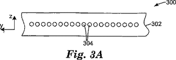
ポリマー繊維204は、多くの異なる方法でマトリックス202内に配列することができる。たとえば、図1に示されているように、繊維204を、マトリックス202の断面積にわたってランダムに位置決めすることができ、図2において、y−z平面内の異なる繊維204の位置はランダムである。他の断面配列を使用することができる。たとえば、光学素子300の断面を示す図3Aに概略的に示された例示的な実施形態において、繊維304は、マトリックス302内に一次元アレイで配列され、隣接した繊維304の間の規則的な間隔がある。この実施形態のいくつかの変更例において、隣接した繊維304の間の間隔は、すべての繊維304について同じである必要はない。光学素子300は偏光子であることができる。
The
光学素子310の断面としての図3Bに概略的に示された別の例示的な実施形態において、繊維314は、マトリックス312内に規則的な二次元アレイで配列される。示された実施形態において、y方向の隣接した繊維314の間の分離距離hyは、z方向の隣接した繊維の間の分離距離hzと同じであるが、そうである必要はなく、図3Cに概略的に示されているように、z方向の分離距離hzはy方向の分離距離hyと異なることができる。光学素子310は偏光子であることができる。
In another exemplary embodiment schematically illustrated in FIG. 3B as a cross-section of
別の例示的な実施形態において、繊維314は、たとえば図3Dに概略的に示されているように、隣接した行の間でずれていることができ、六角形に詰められた繊維パターンを作る。繊維314の他の規則的なパターンを使用することができるか、繊維314の不規則なパターンを使用することができる。
In another exemplary embodiment, the
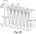
繊維314は、すべて、x軸に実質的に平行であることができるが、そうである必要はなく、いくつかの繊維314が、x軸に対してより大きいかまたはより小さい角度であることができる。たとえば、図3Dに示され、図3Eにさらに示された光学素子310の例において、繊維314が、y−z平面に平行な平面内で互いに平行に、しかし、x軸に対して第1の角度θ1にあるように、繊維314の第1の行316aを配向することができる。第2の行316bの繊維314は、また、y−z平面に平行な平面内で互いに平行に、しかし、必ずしも第1の角度に等しくない、x軸に対する第2の角度θ2にあることができる。また、第3の行316cの繊維314は、y−z軸に平行な平面内で互いに平行に、しかし、x軸に対して第3の角度θ3にあることができる。第3の角度は、第1または第2の角度に等しくても等しくなくてもよい。示された実施形態において、θ3の値はゼロに等しく、第3の行316cの繊維314はx軸に平行である。しかし、θ1、θ2、およびθ3の異なる値は、90°まで達することができる。
The
そのような配列は、1つの行の繊維が、第1の波長帯域内の光について効果的であり、別の行の繊維が、第1の波長帯域と異なる第2の波長帯域内の光について効果的である場合に、特に有用であることができる。第1の行316aの繊維314が、赤色帯域幅内の反射偏光において効果的であり、第2の行316bの繊維314が、青色帯域幅内の反射偏光において効果的である例示的な例を考慮されたい。したがって、光学素子310が、赤色光および青色光の混合で照明されるべきであった場合、繊維314の第1の行316aは、青色光をすべて通過させ、角度θ1で偏光された赤色光を透過する。繊維314の第2の行316aは、角度θ1で偏光された赤色光を透過し、また、角度θ2に平行に偏光された青色光を透過する。角度θ1およびθ2が90°だけ離された場合、素子310は、1つの偏光状態の赤色光、および直交偏光状態の青色光を透過する。同様に、反射青色光は、反射赤色光に直交して偏光される。繊維314の異なる数の行を、各角度で整列させ、各色帯域について使用することができることが理解されるであろう。
Such an arrangement is such that one row of fibers is effective for light in a first wavelength band and another row of fibers is for light in a second wavelength band that is different from the first wavelength band. It can be particularly useful when effective. Illustrative example where
いくつかの実施形態において、繊維314の密度は、光学素子300、310内で一定であることができるか、光学素子300、310内で変わることができる。たとえば、繊維314の密度は、光学素子300、310の1つの側から減少することができるか、何らかの他の態様で変わることができる。これをさらに示すために、図3Fは、繊維314の密度が素子310にわたって変わる光学素子310の実施形態を概略的に示す。特に、y方向の隣接した繊維の間の間隔は、素子310にわたってyのすべての位置について一定ではない。図3Gは、繊維314の密度が素子310を通して変わる光学素子310を概略的に示す。特に、z方向の隣接した繊維の間の間隔は、素子310を通してzのすべての位置について一定ではない。他の変更例が可能であり、たとえば、最も近い隣の繊維の間の間隔は、y方向およびz方向の両方において変わることができる。
In some embodiments, the density of the
別の実施形態が図3Hに概略的に示されており、光学素子320が、マトリックス322内に埋込まれたポリマー繊維324を有する。この特定の実施形態において、隣接した繊維324の中心間の間隔は、図の中心における1つの領域内で、両側の隣り合っている領域に対して低減される。したがって、充填率、すなわち、繊維324によって占められる素子320の断面積の割合は、その領域内で増加される。充填率のそのような変化は、たとえば、光源326から素子320を透過された光の均一性を向上させるために、有用であることができる。これは、たとえば、素子320が、別々の光源によって照らされる直視スクリーンに含まれる場合、重要であることができ、そのようなデバイスにおいて、見る人に、均一な照明の画像を与えることが重要である。光源が均一な拡散体の後ろに配置される場合、拡散体を透過された光の輝度は、光源の上で最高である。図3Hに示された充填率の変化を使用して、光源326のすぐ上の拡散の量を増加させることができ、したがって、透過光の強度の不均一性を低減する。
Another embodiment is schematically illustrated in FIG. 3H, in which the
本開示の光学素子は、平坦な表面、たとえば、図1Aおよび図1Bに示されているようなx−y平面に平行な平坦な表面を有することができる。素子は、また、所望の光学効果を、偏光子を透過された、または偏光子によって反射された光に与えるように構造化された1つ以上の表面を含むことができる。たとえば、図3Iに概略的に示された1つの例示的な実施形態において、偏光子であることができる光学素子330は、いくつかのポリマー繊維334を含むマトリックス332で形成され、1つ以上の湾曲した表面336を有することができる。湾曲した表面336は、集束または非集束(defocusing)の屈折力を、表面336を透過された光に与える。示された実施形態において、光線338が、湾曲した屈折表面336によって集束された、光学素子330の透過軸に平行に偏光された光線の例を表す。他の例示的な実施形態において、それを通って光が素子330に入る素子330の入力表面が、湾曲していることができるか、他の表面構造であることができる。さらに、それを通って透過光が光学素子330を出る出力表面上の表面構造があることができる。表面構造の例としては、フレネルレンズ構造などの構造が挙げられる。そのような構造は、また、屈折力を、構造化表面を通過する光に与えると考えられる。
The optical elements of the present disclosure can have a flat surface, for example, a flat surface parallel to the xy plane as shown in FIGS. 1A and 1B. The element can also include one or more surfaces structured to impart a desired optical effect to light transmitted through or reflected by the polarizer. For example, in one exemplary embodiment schematically illustrated in FIG. 3I, an
入力表面および出力表面のいずれかまたは両方の構造化表面は、また、湾曲した領域に加えて、または湾曲した領域の代わりに、直線領域を含むことができる。たとえば、図3Jに概略的に示された別の例示的な実施形態において、ポリマー繊維344を含むマトリックス342で形成された光学素子340に、輝度向上表面と呼ばれるプリズム構造化表面346を設けることができる。輝度向上表面は、一般に、ディスプレイパネルを照明する光の円錐角を低減し、したがって、見る人のための軸上輝度を増加させるために、たとえばバックライト液晶ディスプレイに使用される。図は、素子340に非垂直に入射する2つの光線348および349の例を示す。光線348は、素子340によって透過される偏光状態であり、また、構造化表面346によってz軸の方にそらされる。光線349は、素子340によって拡散反射される偏光状態である。輝度向上表面は、示されているように、プリズム構造が、またx軸に平行である繊維344に平行であるように配列することができる。他の実施形態において、プリズム構造は、繊維の方向に対して、ある他の角度にあることができる。たとえば、リブは、繊維に垂直なy軸に平行に、またはx軸とy軸との間のある角度にあることができる。
The structured surface of either or both of the input surface and the output surface can also include straight areas in addition to or instead of curved areas. For example, in another exemplary embodiment schematically illustrated in FIG. 3J, an
構造化表面を、任意の適切な方法を用いて、マトリックス上に形成することができる。たとえば、マトリックスを、その表面が、工具表面がポリマーマトリックスの表面上に所望の形状を生じさせる微細複製工具などの工具の表面と接触する間、硬化させることができる。 The structured surface can be formed on the matrix using any suitable method. For example, the matrix can be cured while its surface is in contact with the surface of a tool, such as a microreplication tool, where the tool surface produces the desired shape on the surface of the polymer matrix.
ポリマー繊維は、光学素子の異なる領域にわたって存在することができる。図3Jにおいて、ポリマー繊維344は、構造化表面346によって形成された構造347内に配置されないが、素子340の主本体341内にのみ配置される。他の実施形態において、ポリマー繊維344を異なって分配することができる。たとえば、図3Kに概略的に示された光学素子350において、ポリマー繊維344は、素子350の主本体341、およびまた構造化表面346によって形成された構造347内の両方の中に配置される。図3Lに概略的に示された別の例において、ポリマー繊維344は、素子360の構造347内にのみ配置され、素子360の主本体341内に配置されない。
The polymer fibers can be present over different areas of the optical element. In FIG. 3J, the
本発明の別の例示的な実施形態が図3Mに概略的に示されており、素子370はマトリックス372内のポリマー繊維374を有する。この特定の実施形態において、繊維374aのいくつかが、マトリックス372内に完全に埋込まれないが、マトリックス372の表面376を貫通する。
Another exemplary embodiment of the present invention is schematically illustrated in FIG. 3M, where
いくつかの例示的な実施形態において、偏光子内に配置されたポリマー繊維は、少なくとも、複屈折性材料、および別の材料、たとえば、実質的に非複屈折性の材料を含む、大量の異なるポリマー材料を含む。これらの異なる材料を、多くの異なる方法で、たとえば、規則的な交互の層で、または、他方の材料の「プール」内に配置された一方の材料の微細な繊維として、配列することができる。多数の内部複屈折性界面を含むポリマー繊維のいくつかの異なる例示的な実施形態を以下で説明する。マトリックス材料は、繊維の複屈折性材料よりより小さい複屈折を有することができるか、複屈折を有さないことができるか、反対に複屈折性であることができる。たとえば、繊維内の複屈折性材料がnx>nyを有する場合、マトリックス材料はny>nxを有することができる。 In some exemplary embodiments, the polymer fibers disposed in the polarizer comprise a large amount of different, including at least a birefringent material, and another material, eg, a substantially non-birefringent material. Contains polymer material. These different materials can be arranged in many different ways, eg in regular alternating layers or as fine fibers of one material arranged in a “pool” of the other material. . Several different exemplary embodiments of polymer fibers that include multiple internal birefringent interfaces are described below. The matrix material can have a lower birefringence than the birefringent material of the fiber, can have no birefringence, or, conversely, can be birefringent. For example, if the birefringent material in the fiber has a n x> n y, the matrix material can have a n y> n x.
好ましい例示的な実施形態において、複屈折性材料は、配向されると屈折率の変化を経るタイプのものである。したがって、繊維が配向されると、屈折率整合または不整合が、配向の方向に沿って生じる。配向パラメータおよび他の処理条件の注意深い操作によって、複屈折性材料の正のまたは負の複屈折を用いて、所与の軸に沿った光の一方または両方の偏光の拡散反射または透過を誘起することができる。透過と拡散反射との間の相対比は、繊維内の複屈折性界面の集中、繊維の寸法、複屈折性界面における屈折率の差の二乗、複屈折性界面のサイズおよびジオメトリ、ならびに入射放射線の波長または波長範囲などであるがこれらに限定されないいくつかの要因に依存する。 In a preferred exemplary embodiment, the birefringent material is of a type that undergoes a change in refractive index when oriented. Thus, when the fibers are oriented, a refractive index match or mismatch occurs along the direction of orientation. Careful manipulation of orientation parameters and other processing conditions can be used to induce diffuse reflection or transmission of one or both polarizations of light along a given axis using the positive or negative birefringence of the birefringent material be able to. The relative ratio between transmission and diffuse reflection is the concentration of the birefringent interface within the fiber, the fiber dimensions, the square of the refractive index difference at the birefringent interface, the size and geometry of the birefringent interface, and the incident radiation. Depending on several factors such as, but not limited to:
特定の軸に沿った屈折率整合または不整合の大きさは、その軸に沿って偏光された光の散乱度に影響を及ぼす。一般に、散乱パワーは、屈折率不整合の二乗として変わる。したがって、特定の軸に沿った屈折率の不整合が大きいほど、その軸に沿って偏光された光の散乱が強い。逆に、特定の軸に沿った不整合が小さいとき、その軸に沿って偏光された光が、より小さい程度に散乱され、本体の体積を通る透過はますます正反射になる。 The magnitude of the index match or mismatch along a particular axis affects the degree of scattering of light polarized along that axis. In general, the scattering power varies as the square of the refractive index mismatch. Thus, the greater the index mismatch along a particular axis, the stronger the scattering of light polarized along that axis. Conversely, when the mismatch along a particular axis is small, light polarized along that axis is scattered to a lesser extent and transmission through the body volume becomes increasingly specular.
ある軸に沿って、非複屈折性材料の屈折率が複屈折性材料の屈折率と整合する場合、複屈折性材料の部分のサイズ、形状、および密度にかかわらず、電界がこの軸に平行な状態で偏光された入射光が、散乱されないで繊維を通過する。さらに、その軸に沿った屈折率が、また、偏光子本体のポリマーマトリックスの屈折率に実質的に整合する場合、光は、実質的に散乱されないで本体を通過する。本開示の目的のため、屈折率間の差が、多くとも0.05未満、好ましくは、0.03、0.02、または0.01未満であるとき、2つの屈折率の間の実質的な整合が生じる。 If, along an axis, the refractive index of the non-birefringent material matches the refractive index of the birefringent material, the electric field is parallel to this axis, regardless of the size, shape, and density of the birefringent material portion. The incident light polarized in such a state passes through the fiber without being scattered. Furthermore, if the refractive index along its axis is also substantially matched to the refractive index of the polymer matrix of the polarizer body, the light passes through the body without being substantially scattered. For purposes of this disclosure, a substantial difference between the two indices of refraction when the difference between the indices of refraction is at most less than 0.05, preferably less than 0.03, 0.02, or 0.01. Matching occurs.
複屈折性材料と非複屈折性材料との間の屈折率が、ある軸に沿って整合しない場合、繊維は、この軸に沿って偏光された光を散乱させるか反射する。散乱の強度は、少なくとも部分的に、寸法が約λ/30より大きい所与の断面積を有する散乱体について、屈折率不整合の大きさによって定められ、ここで、λは、偏光子内の入射光の波長である。不整合の界面の厳密なサイズ、形状、および整列は、どのくらい多くの光がその界面からさまざまな方向に散乱または反射されるかを定める役割を果たす。散乱層の密度および厚さが十分である場合、多数の散乱理論によれば、散乱体サイズおよび形状の詳細にかかわらず、入射光が、反射または吸収されるが、透過されない。 If the refractive index between the birefringent material and the non-birefringent material does not match along an axis, the fiber scatters or reflects light polarized along this axis. The intensity of the scattering is determined, at least in part, by the magnitude of the refractive index mismatch for a scatterer having a given cross-sectional area greater than about λ / 30, where λ is within the polarizer The wavelength of incident light. The exact size, shape, and alignment of the mismatched interface serves to determine how much light is scattered or reflected from the interface in various directions. If the density and thickness of the scattering layer is sufficient, according to numerous scattering theories, incident light is reflected or absorbed but not transmitted, regardless of the details of the scatterer size and shape.
偏光子での使用前、繊維は、好ましくは、複屈折性材料と非複屈折性材料との間の屈折率差が、第1の軸に沿って比較的大きく、他の2つの直交する軸に沿って小さいように、延伸し、クロス延伸面内方向のいくらかの寸法緩和を可能にすることによって処理される。これは、異なる偏光の電磁放射線について大きい光学的異方性をもたらす。 Prior to use in the polarizer, the fiber preferably has a relatively large refractive index difference between the birefringent material and the non-birefringent material along the first axis and the other two orthogonal axes. Along the cross-stretch in-plane direction to allow some dimensional relaxation. This results in a large optical anisotropy for differently polarized electromagnetic radiation.
本発明の範囲内の偏光子のいくつかが、楕円拡散偏光子である。一般に、楕円拡散偏光子は、延伸方向および非延伸方向の両方に沿って複屈折性材料と非複屈折性材料との間の屈折率の差を有する繊維を使用し、1つの偏光の光を拡散透過または反射することができる。繊維内の複屈折性材料は、また、ポリマーマトリックス材料との複屈折性界面を形成することができ、この場合、これらの界面は、また、延伸方向およびクロス延伸方向の両方について、屈折率不整合を含むことができる。 Some of the polarizers within the scope of the present invention are elliptically diffusing polarizers. In general, elliptically diffusing polarizers use fibers that have a refractive index difference between a birefringent material and a non-birefringent material along both the stretched and non-stretched directions and emit light of one polarization. It can be diffusely transmitted or reflected. The birefringent material in the fiber can also form birefringent interfaces with the polymer matrix material, in which case these interfaces are also non-refractive in both the stretch direction and the cross-stretch direction. Matching can be included.
前方散乱と後方散乱との比は、複屈折性材料と非複屈折性材料との間の屈折率の差、複屈折性界面の集中、複屈折性界面のサイズおよび形状、ならびに繊維の総厚さに依存する。一般に、楕円拡散体が、複屈折性材料と非複屈折性材料との間の比較的小さい屈折率差を有する。 The ratio of forward scattering to backscattering is the difference in refractive index between birefringent and non-birefringent materials, concentration of birefringent interface, size and shape of birefringent interface, and total fiber thickness. Depends on the size. In general, elliptical diffusers have a relatively small refractive index difference between birefringent and non-birefringent materials.
本発明による繊維での使用のために選択される材料、およびこれらの材料の配向度は、好ましくは、完成した繊維内の複屈折性材料および非複屈折性材料が、関連した屈折率が実質的に等しい、少なくとも1つの軸を有するように選択される。典型的には配向の方向に直角な軸であるが、必ずしもそうではない、その軸と関連する屈折率の整合は、その偏光面内の光の反射が実質的にないことをもたらす。 The materials selected for use in the fibers according to the present invention, and the degree of orientation of these materials, is preferably such that the birefringent and non-birefringent materials in the finished fiber have a substantial refractive index associated with them. Are selected to have at least one axis that is equal to each other. A refractive index match associated with that axis, which is typically an axis perpendicular to the direction of orientation, but not necessarily, results in substantially no reflection of light in its plane of polarization.
内部複屈折性界面を有し、かつ、上で説明された偏光子のいくつかの実施形態に使用することができるポリマー繊維の1つの例示的な実施形態が、多層繊維である。多層繊維は、その少なくとも1つが複屈折性である、異なるポリマー材料の多数の層を含む繊維である。いくつかの例示的な実施形態において、多層繊維は、一連の、第1の材料および第2の材料の交互の層を含み、第1の材料は光学的に等方性であり、第2の材料は、複屈折性であり、第1の材料の屈折率とほぼ同じ、1つの軸に沿った屈折率と、等方性材料の屈折率と異なる、直交する軸に沿った屈折率とを有する。そのような構造は、たとえば米国特許第5,882,774号明細書に、より大きい長さで記載されている。 One exemplary embodiment of a polymer fiber that has an internal birefringent interface and that can be used in some embodiments of the polarizer described above is a multilayer fiber. A multilayer fiber is a fiber comprising multiple layers of different polymeric materials, at least one of which is birefringent. In some exemplary embodiments, the multilayer fiber comprises a series of alternating layers of a first material and a second material, the first material being optically isotropic, The material is birefringent and has a refractive index along one axis that is approximately the same as the refractive index of the first material and a refractive index along an orthogonal axis that is different from the refractive index of the isotropic material. Have. Such a structure is described in greater length, for example in US Pat. No. 5,882,774.
多層繊維400の1つの例示的な実施形態の断面が、図4Aに概略的に示されている。繊維400は、第1の材料402および第2の材料404の交互の層を含む。第1の材料は複屈折性であり、第2の材料は実質的に等方性であり、それにより、隣接した層の間の界面406は複屈折性である。この特定の実施形態において、界面406は、実質的に平面であることができ、繊維400の長さに沿って延在することができる。
A cross section of one exemplary embodiment of
繊維400は、クラッディング層408によって囲むことができる。クラッディング層408は、第1の材料402、第2の材料404、繊維が埋込まれたポリマーマトリックスの材料、または何らかの他の材料から製造することができる。クラッディング408は、デバイス全体の性能に機能的に寄与することができるか、クラッディングは、機能を行わないことができる。クラッディング408は、繊維およびマトリックスの界面における光の偏光解消を最小にすることによってなど、反射偏光子の光学的特性を機能的に向上させることができる。任意に、クラッディング408は、繊維と連続相材料との間の所望のレベルの接着をもたらすことによってなど、偏光子を機械的に向上させることができる。いくつかの実施形態において、クラッディング408は、たとえば、繊維400と周囲のポリマーマトリックスとの間のいくらかの屈折率整合をもたらすことによって、反射防止機能を提供するために使用することができる。
The
繊維400は、繊維400の所望の光学特徴に依存して、異なる数の層で、および異なるサイズで、形成することができる。たとえば、繊維400は、約10の層から何百もの層で、関連した厚さ範囲で、形成することができる。繊維400の幅の制限はないが、幅の好ましい値は、5μmから約5000μmの範囲内に入ることができるが、繊維幅は、また、この範囲の外側になることができる。
The
材料の多数の層を多層フィルムに共押出しし、次いで、複屈折性材料を配向し、複屈折性界面を生じさせるようなその後の延伸工程によって、多層繊維400を製造することができる。多層シートをスライスすることによって、多層繊維を得ることができる。複屈折性界面を含む多層シートを製造するためのいくつかの方法が、たとえば、米国特許第5,269,995号明細書;米国特許第5,389,324号明細書;および米国特許第5,612,820号明細書に、さらに記載されている。
Multiple layers of
複屈折性材料として使用することができる適切なポリマー材料のいくつかの例としては、上で説明されたような、PET、PEN、およびそれらのさまざまなコポリマーが挙げられる。非複屈折性材料として使用することができる適切なポリマー材料のいくつかの例としては、上で説明された光学的に等方性の材料が挙げられる。 Some examples of suitable polymeric materials that can be used as the birefringent material include PET, PEN, and various copolymers thereof, as described above. Some examples of suitable polymeric materials that can be used as the non-birefringent material include the optically isotropic materials described above.
多層繊維の他の構成を使用することができる。たとえば、多層繊維420の別の例示的な実施形態を、交互の第1の材料422および第2の材料424の同心層で形成することができ、第1の材料422は複屈折性であり、第2の材料424は等方性である。この例示的な実施形態において、繊維420は、繊維420に沿って延在する、交互の層422、424の間の同心複屈折性界面426を含む。
Other configurations of multilayer fibers can be used. For example, another exemplary embodiment of
繊維420の外層428を、第1および第2の材料、偏光子のポリマーマトリックスに使用されるのと同じポリマー材料、または何らかの他の材料の1つから形成することができる。
The
繊維420は、反射および波長依存などの所望の光学特徴を提供するために、任意の適切な数の層および層厚さで形成することができる。たとえば、繊維420は、10の層から何百もの層を含むことができる。同心繊維420は、多層形態を共押出しし、次いで、延伸して複屈折性材料を配向することによって、形成することができる。平坦な多層繊維400での使用のために上に記載された材料のいずれかを、また、同心繊維420に使用することができる。
The
異なるタイプの断面を有する多層繊維も使用することができる。1つのそのような例が、図4Cに断面で概略的に示された多層繊維440である。この繊維は、多数の、第1の材料442および第2の材料444の交互の層を含み、第1の材料442は複屈折性であり、第2の材料444は光学的に等方性である。異なる層の間に形成された複屈折性界面446は、平坦な部分446aと、湾曲した部分446bとを有し、繊維440に沿って延在する。異なる層の特定の断面形状は、主として、繊維440を共押出しするために使用されるフィードブロックの形状によって、およびまた、いかなるその後の繊維440の形成によっても定められる。
Multilayer fibers having different types of cross-sections can also be used. One such example is the
外層448は、第1または第2の材料、繊維440が埋込まれたポリマーマトリックスと同じ材料、または何らかの他の材料から形成することができる。外層408、428、448の材料は、ポリマー繊維と周囲のポリマーマトリックスとの間の所望の接着特性を提供するように選択することができる。たとえば、いくつかの実施形態において、外層408、428、448は、ポリエステル樹脂、シラン、または、ポリマー繊維とポリマーマトリックスとの間の接着を増加させるために使用される何らかの他の剤から形成することができる。他の実施形態において、外層408、428、448は、ポリマー繊維と周囲のポリマーマトリックスとの間の接着を低減する材料、たとえば、フルオロカーボン材料、シリコーン材料などから製造することができる。いくつかの実施形態において、たとえば、ポリマー繊維とポリマーマトリックスとの間のいくらかの屈折率整合をもたらすことによって、反射防止機能を提供するために、外層を使用することができる。
The
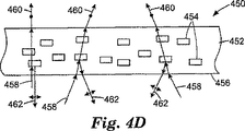
多層繊維が、繊維断面上で平坦な部分を有する複屈折性界面を含む場合、ある範囲の選択された効果をもたらすように、平坦な部分の配向を偏光子内で制御することができる。たとえば、図4Dに概略的に示された偏光子450の例示的な実施形態において、偏光子450は、複屈折性界面が一般に偏光子450の表面456と平行に整列された繊維454が埋込まれたマトリックス452を含む。入射光458が偏光されていない場合、偏光子は、1つの偏光状態の光460を通過させ、直交偏光状態の光462を反射する。示された実施形態において、透過光460は図の平面の外に偏光され、反射光462は図の平面に平行に偏光される。
If the multilayer fiber includes a birefringent interface having a flat portion on the fiber cross section, the orientation of the flat portion can be controlled in the polarizer to provide a range of selected effects. For example, in the exemplary embodiment of
この例示的な実施形態において、反射光462は、かなりの正成分を含むことができ、というのは、繊維454の複屈折性界面が互いに平行に整列されるからである。反射光462は、また、たとえば、表面および回折効果によって、ならびに、また、繊維454の間の真の平行からの整列不良のため、拡散成分を含むことができる。さらに、複屈折性界面が表面456に平行に整列されるので、偏光子450は、反射偏光状態の光について、幾分、鏡のように機能する。
In this exemplary embodiment, the reflected light 462 can include a significant positive component because the birefringent interfaces of the
偏光子470の別の例示的な実施形態が、図4Eに断面で概略的に示されている。この偏光子470において、繊維454は、複屈折性界面の平坦な部分が互いに実質的に平行な状態で整列される。しかし、この場合、複屈折性界面の平坦な部分は、表面456に平行に整列されないが、表面456に非平行に整列される。非偏光入射光458が、透過偏光状態の光460の透過、および反射偏光状態の光462の反射をもたらす。この場合、入射光が表面456に垂直に入射すると、反射光462を、一般に、表面456に非垂直な方向に反射することができる。反射光462は、偏光子470の側に向けられるということができる。
Another exemplary embodiment of a
偏光子480の別の例示的な実施形態が、図4Fに断面で概略的に示されている。この偏光子480において、繊維454は、複屈折性界面の平坦な部分がすべて平行な状態で整列されないが、偏光子480にわたって所望の配向プロファイルで配向される。説明のため、複屈折性界面の平坦な部分に対する法線482と表面456に対する法線484との間に形成された角度θを規定することが有用である。θの値は、偏光子480にわたって変わることができる。示された実施形態において、偏光子480の左側の方の繊維454は、θの値が+θ0であるように配向される。したがって、偏光子480のこの部分から反射された光462Lは、右の方に向けられる。偏光子480の右側の方の繊維454は、θの値が−θ0であるように配向され、したがって、偏光子のこの側から反射された光462Rは、左の方に向けられる。偏光子の中心において、複屈折性界面の平坦な部分および表面456に対する法線482、484は、ほぼ平行であり(すなわち、θ=0)、したがって、偏光子480の中心で反射された光462Cは、表面456上でほぼ入射角で反射される。
Another exemplary embodiment of a
光を所定のプロファイルで反射するように、θが偏光子480にわたって変わる態様を選択することができることが理解されるであろう。たとえば、示された実施形態において、反射光を、ほぼ、偏光子の前の焦点に導くことができる。示されていない別の例示的な実施形態において、反射光が、偏光子の前ではなく、偏光子の側の焦点に導かれるように、複屈折性界面の平坦な部分を配向することができる。
It will be appreciated that the manner in which θ varies across the
偏光子490の別の例示的な実施形態が、図4Gに概略的に示されている。この偏光子490において、異なる繊維454の複屈折性界面の平坦な部分は、ランダムに配向される。結果として、反射光462は、多少拡散的に反射される。
Another exemplary embodiment of a
反射光が、多少、正反射されるか、拡散反射されるか、正特徴および拡散特徴のある組合せで反射されるように、複屈折性界面の平坦な部分の相対配向を選択することができることが理解されるであろう。 The relative orientation of the flat portion of the birefringent interface can be selected so that the reflected light is somewhat specularly reflected, diffusely reflected, or reflected by some combination of positive and diffuse features. Will be understood.
いくつかの例示的な実施形態において、繊維454は、それらの長さに沿って、表面456に対して、一定の配向を維持する。他の例示的な実施形態において、繊維454のいくつかまたはすべてを、それらの長さに沿って撚ることができる。
In some exemplary embodiments, the
内部複屈折性界面を有するポリマー繊維の別の例示的な実施形態が、ポリマー充填剤が浸透された多数の散乱繊維を含む複合繊維である。例示的な複合繊維の断面の例が、図5Aに概略的に示されている。複合繊維500は、散乱繊維502間の充填剤504とともに、多数の散乱繊維502を含む。いくつかの実施形態において、散乱繊維502または充填剤504の少なくとも一方が複屈折性である。たとえば、いくつかの例示的な実施形態において、散乱繊維502の少なくともいくつかを複屈折性材料から形成することができ、充填剤材料504は非複屈折性であることができる。他の例示的な実施形態において、散乱繊維502は非複屈折性であることができ、充填剤材料504は複屈折性である。他の実施形態において、散乱繊維502および充填剤504の両方が複屈折性であることができる。これらの異なる変更例において、散乱繊維502の材料と充填剤材料504との間の各界面508は、複屈折性材料と別の材料との間の界面であり、すなわち、複屈折性界面であり、選択された偏光状態の光の優先的な反射または散乱に寄与することができる。これらの異なる実施形態の各々において、複合繊維が埋込まれたポリマーマトリックスは、光学的に等方性または複屈折性であることができる。
Another exemplary embodiment of a polymer fiber having an internal birefringent interface is a composite fiber that includes a number of scattering fibers impregnated with a polymer filler. An example cross-section of an exemplary bicomponent fiber is schematically illustrated in FIG. 5A. The
いくつかの他の実施形態において、繊維500は、等方性充填剤材料504とともに等方性散乱繊維502から製造することができる。そのような場合、繊維500が埋込まれたマトリックスは複屈折性である。
In some other embodiments, the
複合繊維500は、異なる断面形状を呈することができる。図5Aにおいて、複合繊維500は円形断面形状を有する。それぞれ図5Bおよび図5Cに概略的に示された複合繊維510および520の他の例示的な実施形態は、楕円形および正方形断面形状を有する。他の断面形状、たとえば、規則的なおよび不規則な多角形形状、または湾曲した辺および直線の辺を組合せる断面形状を使用することができる。示された実施形態は、例示にすぎないことが意図され、決して限定することは意図されていない。
The
複合繊維に、任意に、外層506を設けることができる。外層506は、たとえば、複合繊維と複合繊維が埋込まれたポリマーマトリックスとの間の接着に影響を及ぼすために使用することができる。いくつかの実施形態において、外層506は、複合繊維とポリマーマトリックスとの間の接着を増加させる材料、たとえば、ポリエステル樹脂コーティング、シランコーティング、または、ポリマーマトリックスとポリマー繊維との間の接着を増加させるために使用される他のプライマーから形成することができる。他の実施形態において、外層506は、ポリマー繊維と周囲のポリマーマトリックスとの間の接着を低減する材料、たとえば、フルオロカーボン材料、シリコーン材料などから製造することができる。いくつかの実施形態において、外層506は、たとえば、繊維500と周囲のポリマーマトリックスとの間のいくらかの屈折率整合をもたらすことによって、反射防止機能を提供するために使用することができる。
An
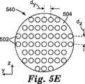
散乱繊維の位置は、たとえば、図5A〜5Cの例示的な実施形態に概略的に示されているように、複合繊維の断面内でランダムであることができる。散乱繊維の他の断面配列を使用することができる。たとえば、散乱繊維502を、複合繊維530の断面内に規則的に配列することができる。たとえば、図5Dに示された繊維530の例示的な実施形態は、y方向の隣接した散乱繊維502の間の分離距離dyが、z方向の隣接した散乱繊維502の間の分離距離dzと同じである二次元アレイで配列された散乱繊維502を示す。図5Eに示された繊維540の例示的な実施形態において、散乱繊維502は、y方向の分離距離dyがz方向の分離距離dzと異なる二次元アレイで配列される。図5Dおよび図5Eの散乱繊維502は、矩形格子パターンにあり、これは、図5Dの正方形格子パターンを含むことが理解される。複合繊維530、540が、可視光で使用されるべきである場合、隣接した散乱繊維502の間の間隔は、たとえば、50nm〜500nmの範囲内であることができる。
The location of the scattering fibers can be random within the cross-section of the composite fiber, for example, as schematically illustrated in the exemplary embodiment of FIGS. Other cross-sectional arrangements of scattering fibers can be used. For example, the scattering
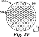
散乱繊維502の他の規則的な配列が可能である。たとえば、図5Fに断面で概略的に示された複合繊維550において、散乱繊維502は、y方向に沿って行にあり、隣接した行はy方向に互いにずれている。この特定の実施形態において、隣接した行の間のずれは、散乱繊維502が、正方形または矩形パターンではなく、六角形パターンで配列されるようなものである。図5Fの配列の変更例が、図5Gの複合繊維555について概略的に示されており、最も近い隣り合う散乱繊維502の間の分離は、z方向において、y方向においてより大きい。
Other regular arrangements of scattering
他の例示的な実施形態において、散乱繊維502は他のパターンを形成することができる。たとえば、散乱繊維を、規則的なアレイ内の、いくつかの、しかしすべてではない位置を充填するように配列することができる。さらに、空間または間隙を、隣接した散乱繊維または散乱繊維のグループの間に導入することができる。そのようなグループまたは空間および間隙のサイズおよび分布は、特に望ましいスペクトル特徴を生じさせるように選択することができる。たとえば、散乱繊維のいくつかの配列が、特定の波長範囲内の光について、フォトニック結晶として作用することができ、これは、スペクトル的に選択的な反射および/または透過をもたらすことができる。フォトニック結晶フォトニック繊維が、代理人整理番号60371US002を有する、2005年2月28日に出願された、「複合ポリマー繊維(COMPOSITE POLYMER FIBERS)」という名称の共有米国特許出願第11/068,158号明細書に、さらに記載されている。
In other exemplary embodiments, the scattering
可能な散乱繊維配列の網羅的でない選択を示す複合繊維の付加的な例示的な実施形態をここで説明する。 Additional exemplary embodiments of bicomponent fibers will now be described that show an incomplete selection of possible scattering fiber arrays.
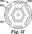
図5Hに概略的に示された複合繊維560の例示的な実施形態において、いくつかの散乱繊維502が、繊維560の中心の周りの領域内に規則的に配列されるが、繊維560の中心部分は散乱繊維がない。図5Iに概略的に示された複合繊維565の別の例において、散乱繊維502は同心リング506で配列される。散乱繊維502のサイズ、ならびに間隙および/または同心リングのサイズは、透過および/または反射などの特定の光学特性のために選択することができる。図5Iに示された例において、散乱繊維は、六角形格子によって設定された位置にリングで配置されるように示されている。これは、必要な条件ではなく、散乱繊維502は、たとえば図5Jに概略的に示されているように、半径方向に同心のパターンで形成することができる。
In the exemplary embodiment of the
いくつかの実施形態において、散乱繊維502は、すべて、同じサイズである必要はない。たとえば、図5Jおよび図5Kに示された複合繊維570および575の実施形態について示されているように、複合繊維は、異なる断面サイズの散乱繊維を含むことができる。これらの特定の実施形態において、散乱繊維502aは、散乱繊維502bより断面が比較的より大きい。散乱繊維502は、少なくとも2つの異なるサイズのグループに分かれることができ、実際には、すべて、異なるサイズであることができる。さらに、たとえば図5Iに示されているように、散乱繊維502を複合繊維の中心に配置することができるか、複合繊維の中心に散乱繊維502がないことができ、たとえば、散乱繊維502aは、図5Jの複合繊維570の中心を囲んで位置決めされるが、複合繊維570の中心に位置決めされない。実際には、散乱繊維502の寸法は、1つの値であるのではなく、ある範囲内に入ることができる。さらに、異なる散乱繊維502を異なる材料から形成することができる。
In some embodiments, the scattering
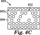
上で説明されたように、複合繊維は、形状が円形である必要はなく、非円形断面を有することができる。図示において、図6Aおよび図6Bは、それぞれ正方形パターンおよび六角形パターンで散乱繊維502を含む非円形複合繊維600、610を示す。非円形繊維は、その散乱繊維502が、規則的な格子パターン上のポイントに位置決めされることができるが、格子パターンのすべての位置が散乱繊維502と関連する必要はない。たとえば、図6Cに概略的に示された非円形複合繊維620は、六角形格子上に位置決めされた散乱繊維502を含むが、いくつかの間隙612が繊維間に存在することができる。さらに、散乱繊維502によって形成されたパターンは、対称軸を有さない。
As explained above, the bicomponent fibers need not be circular in shape and can have a non-circular cross-section. In the illustration, FIGS. 6A and 6B show non-circular
非円形複合繊維630、640の他の例示的な実施形態が、図6Dおよび図6Eに概略的に示されている。これらの例示的な非円形複合繊維630、640は、断面が正方形であり、異なる例示的なパターンで配列された散乱繊維502を含む。複合繊維630内の散乱繊維502は六角形格子パターン上に配列され、複合繊維640内の散乱繊維502は正方形格子パターンで配列される。各場合において、散乱繊維502の配列内の間隙がある。
Other exemplary embodiments of non-circular
本発明の範囲は、複合繊維内の散乱繊維のすべての配列を包含することが意図される。いくつかの例示的な配列において、散乱繊維の相対位置、散乱繊維のサイズ、および散乱繊維と充填剤材料との間の屈折率の差を、たとえば反射および/または透過における、所望のスペクトル的に選択的な特性を、複合繊維に与えるように設定することができる。そのようなスペクトル的に選択的な特性の例としては、反射および透過が挙げられるが、これらに限定されない。複合繊維のいくつかの実施形態において、散乱繊維の断面位置は、入射光の非干渉性散乱をもたらすことができる。他の実施形態において、散乱繊維の位置は、フォトニック結晶特性を生じさせる散乱光の干渉性効果をもたらすことができる。複合繊維内の散乱繊維の平均密度は、大きい範囲、たとえば、約1%から約95%、好ましくは約10%から約90%、より好ましくは約10%から約50%にわたることができるが、散乱繊維密度は、また、これらの範囲の外側になることができる。複合繊維は、代理人整理番号60371US002を有する、2005年2月28日に出願された、「複合ポリマー繊維(COMPOSITE POLYMER FIBERS)」という名称の共有米国特許出願第11/068,158号明細書に、より詳細に記載されている。 The scope of the present invention is intended to encompass all arrangements of scattering fibers within a composite fiber. In some exemplary arrangements, the relative position of the scattering fibers, the size of the scattering fibers, and the difference in refractive index between the scattering fibers and the filler material can be determined spectrally as desired, for example in reflection and / or transmission. Selective properties can be set to impart to the composite fiber. Examples of such spectrally selective properties include, but are not limited to, reflection and transmission. In some embodiments of the composite fiber, the cross-sectional position of the scattering fiber can provide incoherent scattering of incident light. In other embodiments, the location of the scattering fibers can provide a coherent effect of scattered light that produces photonic crystal properties. The average density of scattering fibers within the composite fiber can range over a large range, for example from about 1% to about 95%, preferably from about 10% to about 90%, more preferably from about 10% to about 50%, The scattering fiber density can also be outside of these ranges. The composite fiber is disclosed in commonly-owned US patent application Ser. No. 11 / 068,158, filed Feb. 28, 2005, having the agent serial number 60371US002, entitled “COMPOSITE POLYMER FIBERS”. Are described in more detail.
散乱繊維502のサイズは、散乱に著しい影響を及ぼすことができる。散乱効果のプロットとして、規格化されスケール変更された光学的厚さ(NSOT)が、散乱繊維の平均半径の関数として、図7に示されている。NSOTは次の式によって与えられ、
NSOT=τ(1−g)/(tf)
式中、τは、光学厚さであり、tkに等しく、kは、単位体積あたりの消光断面積(消光に対する平均自由行程の逆数)であり、tは、拡散体の厚さであり、fは、拡散体の体積分率であり、gは、非対称パラメータである。gの値は、純粋前方散乱の場合+1であり、純粋後方散乱の場合−1であり、均等前方および後方散乱の場合ゼロである。プロットを生じさせるために使用された計算は、入射光の真空波長が550nmであることを想定した。
The size of the scattering
NSOT = τ (1-g) / (tf)
Where τ is the optical thickness and is equal to tk, k is the extinction cross section per unit volume (reciprocal of mean free path for quenching), t is the thickness of the diffuser, f Is the volume fraction of the diffuser and g is the asymmetric parameter. The value of g is +1 for pure forward scattering, -1 for pure backscattering, and zero for uniform forward and backscattering. The calculation used to generate the plot assumed that the vacuum wavelength of the incident light was 550 nm.
図からわかるように、散乱効果は、約150nmの半径においてピークに達し、約50nm〜1000nmの半径範囲にわたって、最大の約半分の値を有する。散乱繊維は任意の所望の断面寸法を有することができるが、断面寸法は、約550nmの波長を中心とする光について、約50nmから約2000nmの範囲内、より好ましくは約100nmから約1000nmの範囲内であることができる。断面寸法は、散乱繊維がほぼ円形断面を有する場合、直径であり、非円形繊維断面の場合、散乱繊維幅とみなすことができる。入射光の波長が、スペクトルの可視領域の外側に、たとえば紫外または赤外領域内にある用途のために、複合繊維が使用されている場合、散乱繊維のサイズは異なることができる。一般に、散乱繊維の断面寸法の好ましい範囲が、約λ/10から約4λであり、ここで、λは光の真空波長である。光がある範囲の波長内に存在する場合、λの値は、波長範囲の中心値とみなすことができるが、複合繊維に、また、ある範囲の寸法を有する散乱繊維を設けることができる。 As can be seen, the scattering effect peaks at a radius of about 150 nm and has a value of about half of the maximum over a radius range of about 50 nm to 1000 nm. The scattering fibers can have any desired cross-sectional dimension, but the cross-sectional dimension is in the range of about 50 nm to about 2000 nm, more preferably in the range of about 100 nm to about 1000 nm for light centered at a wavelength of about 550 nm. Can be within. The cross-sectional dimension is the diameter if the scattering fiber has a substantially circular cross section, and can be considered the scattering fiber width if it is a non-circular fiber cross section. If the composite fiber is used for applications where the wavelength of the incident light is outside the visible region of the spectrum, for example in the ultraviolet or infrared region, the size of the scattering fiber can be different. In general, the preferred range of cross-sectional dimensions of the scattering fibers is from about λ / 10 to about 4λ, where λ is the vacuum wavelength of light. If light is present within a range of wavelengths, the value of λ can be considered the center value of the wavelength range, but the composite fiber can also be provided with scattering fibers having a range of dimensions.
散乱繊維が小さすぎる、たとえば、複合繊維内の光の波長の約30分の1未満、または真空中の550nmにおける光について約0.012μm未満である場合、および、散乱繊維の密度が十分に高い、たとえば、複合繊維体積の約60%〜80%の範囲内である場合、偏光子は、任意の所与の軸に沿った散乱繊維および充填剤の屈折率にある程度存在する有効屈折率を有する媒体として機能し得る。そのような場合、光がほとんど散乱されない。散乱繊維の断面サイズが、光波長より著しく大きく、たとえば、波長の少なくとも約3倍以上になると、散乱効率は非常に低くなり、真珠光沢効果が生じることがある。 If the scattering fibers are too small, for example, less than about 1/30 of the wavelength of light in the composite fiber, or less than about 0.012 μm for light at 550 nm in vacuum, and the density of the scattering fibers is sufficiently high For example, when in the range of about 60% to 80% of the composite fiber volume, the polarizer has an effective refractive index that is present to some extent in the refractive index of the scattering fiber and filler along any given axis. It can function as a medium. In such a case, little light is scattered. If the cross-sectional size of the scattering fiber is significantly larger than the light wavelength, for example at least about 3 times the wavelength or more, the scattering efficiency will be very low and a nacreous effect may occur.
散乱繊維の断面寸法は、光学材料の所望の用途に依存して変わることができる。したがって、たとえば、散乱繊維の寸法は、特定の用途における対象となる光の波長に依存して変わることができ、異なる寸法が、可視光、紫外光、および赤外光を散乱または透過するために必要とされる。しかし、一般に、散乱繊維の寸法は、およそ、材料中の対象となる波長範囲内の光の最も小さい波長の約30分の1より大きくなければならない。 The cross-sectional dimensions of the scattering fibers can vary depending on the desired application of the optical material. Thus, for example, the dimensions of the scattering fiber can vary depending on the wavelength of light of interest in a particular application, and different dimensions can scatter or transmit visible, ultraviolet, and infrared light. Needed. In general, however, the size of the scattering fiber should be approximately greater than about one-third of the smallest wavelength of light within the wavelength range of interest in the material.
所望の寸法範囲の上側において、散乱繊維の平均寸法は、好ましくは、材料中の対象となる波長範囲にわたる光の波長の2倍以下、好ましくは所望の波長の0.5未満である。 Above the desired size range, the average size of the scattering fibers is preferably no more than twice the wavelength of light over the wavelength range of interest in the material, preferably less than 0.5 of the desired wavelength.
複合繊維内の散乱繊維の密度は、生じる散乱の量に影響を及ぼす。散乱繊維間の中心間の間隔が、約λ/10から約2λであることが有用であることができ、ここで、λは、入射光の中心または平均真空波長である。 The density of scattering fibers within the composite fiber affects the amount of scattering that occurs. It can be useful that the center-to-center spacing between the scattering fibers is about λ / 10 to about 2λ, where λ is the center of the incident light or the average vacuum wavelength.
散乱繊維は、断面が円形であることができるが、円形である必要はなく、他の断面形状を有することができる。図6Fに断面で概略的に示された例示的な複合繊維650において、散乱繊維652は正方形断面を有する。断面の他の形状、たとえば、三角形、矩形、もしくは六角形などの、規則的なおよび不規則な多角形形状、または湾曲した辺および直線の辺を組合せる断面形状を使用することができる。散乱繊維の断面形状は、押出ダイの形状の結果であることができるか、押出後の光学素子の後処理の結果であることができる。本発明を、図に示されたそれらの断面形状を有する散乱繊維に限定することは意図されていない。
The scattering fibers can be circular in cross section, but need not be circular, and can have other cross-sectional shapes. In the exemplary
中心間の繊維間隔が不均一である場合、非円形断面を有する散乱繊維の使用が有用であり、というのは、それは、散乱繊維が、複合繊維の断面積のより大きい割合を充填することを可能にするからである。たとえば、散乱繊維が矩形格子上に配列され、中心間の間隔が、y方向においてz方向の2倍も大きい場合、散乱繊維は、散乱繊維がy方向においてz方向より2倍も長い楕円形断面を有する場合、散乱繊維が円形であった場合より大きい複合繊維断面を充填する。 When the center-to-center fiber spacing is non-uniform, the use of scattering fibers with non-circular cross sections is useful because it indicates that the scattering fibers fill a larger percentage of the cross-sectional area of the composite fiber. It is possible. For example, if the scattering fibers are arranged on a rectangular grid and the center-to-center spacing is twice as large as the z direction in the y direction, the scattering fiber is an elliptical cross section in which the scattering fibers are twice as long as the z direction When the scattering fiber is circular, it fills a larger cross section of the composite fiber.
非円形断面を有する散乱繊維のいくつかの付加的な例示的な配列が、図6G〜6Iに概略的に示されている。非円形散乱繊維は、それらの断面形状がランダムな方向に配列された状態で配列することができる。他の実施形態において、散乱繊維の断面を、互いに対して整列させることができる。たとえば、図6Gにおいて、複合繊維660は、楕円形断面を有する散乱繊維662が埋込まれた充填剤504で形成される。この特定の実施形態において、散乱繊維662は、それらの断面楕円の長軸がy軸と平行な状態で整列される。
Some additional exemplary arrangements of scattering fibers having a non-circular cross-section are schematically illustrated in FIGS. Non-circular scattering fibers can be arranged with their cross-sectional shapes arranged in random directions. In other embodiments, the cross-sections of the scattering fibers can be aligned with respect to each other. For example, in FIG. 6G, the composite fiber 660 is formed of a
散乱繊維は、それらの断面がすべて整列した状態で配列する必要はないが、異なる散乱繊維が、複合繊維内の異なる整列を有することができる。図6Hに概略的に示された複合繊維670の例示的な実施形態において、散乱繊維672は楕円形断面を有し、いくつかの繊維672aが、それらの長軸がz軸に平行な状態で配列され、他の繊維672bが、それらの短軸がz軸に平行な状態で配列される。散乱繊維672の約半分が各方向に整列される。また、繊維672aおよび672bの集団は、複合繊維670の断面内で規則的に配列される。繊維672aおよび672bの集団を、また、複合繊維670の断面内で不規則に配列することができることが理解されるであろう。
The scattering fibers need not be arranged with their cross-sections all aligned, but different scattering fibers can have different alignments within the composite fiber. In the exemplary embodiment of the
示された実施形態の他の変更例が可能である。たとえば、すべての散乱繊維が、同じ断面形状、サイズ、または整列を有する必要はない。さらに、散乱繊維は、複合繊維内のパターンを形成するように断面で整列させることができる。そのような複合繊維680の1つの特定の例が、図6Iに概略的に示されている。充填剤504は、2つの異なる断面形状を有する散乱繊維、楕円形繊維682および円形繊維684が埋込まれる。示された実施形態において、楕円形繊維682は、それらの楕円形断面の短軸が最も近い円形繊維684の方に向けられるように整列される。散乱繊維の他のパターンを使用することができる。
Other variations of the illustrated embodiment are possible. For example, not all scattering fibers need have the same cross-sectional shape, size, or alignment. Furthermore, the scattering fibers can be aligned in cross section to form a pattern within the composite fiber. One particular example of such a
散乱繊維が非円形断面を有する場合、散乱繊維は、複合繊維内に撚られない状態であることができ、散乱繊維の面が、散乱繊維の長さに沿って、複合繊維の1つの面の方に配向される。他の例示的な実施形態において、散乱繊維を複合繊維内で撚ることができ、散乱繊維の長さに沿って異なるポイントにおいて、散乱繊維の面が、複合繊維の異なる面の方に配向される。 If the scattering fiber has a non-circular cross-section, the scattering fiber can be untwisted into the composite fiber so that the surface of the scattering fiber is one of the faces of the composite fiber along the length of the scattering fiber. Oriented in the direction. In other exemplary embodiments, the scattering fibers can be twisted within the composite fiber, and at different points along the length of the scattering fiber, the face of the scattering fiber is oriented toward a different face of the composite fiber. The
複合繊維の多くの実施形態において、複屈折性界面は、湾曲していることができるか、平坦であり、かつ整列されていないことができる。そのような実施形態において、光は複屈折性界面で多くの異なる方向に反射され、したがって、複合繊維は、光を散乱すると説明することができる。 In many embodiments of bicomponent fibers, the birefringent interface can be curved or flat and unaligned. In such an embodiment, light is reflected in many different directions at the birefringent interface, and thus the composite fiber can be described as scattering light.
屈折率不整合が、複合繊維内の偏光依存散乱を促進するために依拠する主な要因であるが、複合繊維の断面形状も、散乱に影響を及ぼすことができる。たとえば、散乱繊維が、断面が楕円形である場合、楕円形断面形状は、後方散乱光および前方散乱光の両方の非対称拡散に寄与することができる。この影響は、屈折率不整合による散乱量を増加させる場合も減少させる場合もある。 Although refractive index mismatch is a major factor that relies on to promote polarization-dependent scattering within composite fibers, the cross-sectional shape of composite fibers can also affect scattering. For example, if the scattering fiber is elliptical in cross section, the elliptical cross sectional shape can contribute to asymmetric diffusion of both backscattered light and forward scattered light. This effect may increase or decrease the amount of scattering due to refractive index mismatch.
いくつかの実施形態において、散乱繊維は、コアおよびシェル構造を有することができ、コアおよびシェルは、同じまたは異なる材料から製造されるか、コアは中空である。したがって、たとえば、散乱繊維は、均一なまたは不均一な断面の中空繊維であることができる。繊維の内部空間は、空であることができるか、固体、液体、または気体であることができ、有機または無機であることができる適切な媒体によって占めることができる。媒体の屈折率は、複屈折性界面における所望の反射度または散乱度を達成するように、複屈折性界面における屈折率差を考慮して選択することができる。適切な等方性ポリマー材料および複屈折性ポリマー材料を上で説明した。 In some embodiments, the scattering fibers can have a core and shell structure, where the core and shell are made from the same or different materials, or the core is hollow. Thus, for example, the scattering fibers can be hollow fibers of uniform or non-uniform cross section. The interior space of the fiber can be empty, can be solid, liquid, or gas, and can be occupied by a suitable medium that can be organic or inorganic. The refractive index of the medium can be selected taking into account the refractive index difference at the birefringent interface so as to achieve the desired reflectivity or scattering at the birefringent interface. Suitable isotropic and birefringent polymer materials have been described above.
複合繊維を製造する1つの方法は、複合繊維を製造するために設計されたフィードブロックを使用して、ときにはまた「海島(island−in−the−sea)」繊維として知られている多数の散乱繊維を共押出しすることである。そのような方法は、繊維科学技術ハンドブック:先端技術繊維パートD(Handbook of Fiber Science and Technology: High Technology Fibers Part D)、Vol.3;ルーイン(Lewin)およびプレストン(Preston)(編)、マーセル・デッカー(Marcel Dekker)、1996年、ISBN 0−8247−9470−2に、より詳細に記載されている。この引例に記載されたものを含む他の繊維構造および断面分布を使用することができる。複合繊維を、押出後、延伸して、複屈折性材料を配向することができる。散乱繊維を含む素子を共押出しする方法のより詳細な説明が、米国特許出願第11/068,159号明細書(2005年2月28日に出願された、「共連続相を有する複合ポリマー光学フィルム(COMPOSITE POLYMERIC OPTICAL FILMS WITH CO−CONTINUOUS PHASES)」、代理人整理番号60401US002)に、示されている。 One method of producing bicomponent fibers uses feedblocks designed to produce bicomponent fibers, and a number of scatterings, sometimes also known as “island-in-the-sea” fibres. Co-extrusion of fibers. Such methods are described in Textile Science and Technology Handbook: Handbook of Fiber Science and Technology: High Technology Fibers Part D), Vol. 3; Lewin and Preston (ed.), Marcel Dekker, 1996, ISBN 0-8247-9470-2, in more detail. Other fiber structures and cross-sectional distributions can be used including those described in this reference. The bicomponent fibers can be stretched after extrusion to orient the birefringent material. A more detailed description of a method for coextrusion of elements containing scattering fibers is described in US patent application Ser. No. 11 / 068,159 (filed Feb. 28, 2005, “Composite Polymer Optics with Cocontinuous Phases”). Film (COMPOSITE POLYMERIC OPTICAL FILMS WITH CO-CONTINUOUS PHASES), agent reference number 60401US002).
複合繊維を共押出しする例において、118のレーザ機械加工プレートと、11のエンドミル加工したプレートとを有するフィードブロックを、2つの入力ポートと、約1000の「島」出力ポートとを有するように組立てた。フィードブロック内で、ポリマー経路は、すべて、実質的に等しい長さである。結果として生じる共押出物(coextrudant)複合繊維の断面が、図14の写真に示されている。複合繊維は、テネシー州キングズポートのイーストマン・ケミカル・カンパニーによって供給された、PETGコポリエステル、イースター(登録商標)6763の充填剤「海」の中の、散乱繊維「島」としてのPEN(90%)/PET(10%)コポリマーを含んだ。押出された複合繊維は直径約200μmである。複合繊維は、延伸しなかったが、幾何学的形状を維持しながらの延伸で、約25μmの直径、すなわち、約87%の直径の低減に達することができる。そのような延伸において、散乱繊維間の間隔は約500nmであろう。散乱繊維の断面寸法は、2つの異なるポリマー材料の流量の比に依存する。 In the example of co-extrusion of bicomponent fibers, a feedblock having 118 laser machined plates and 11 end milled plates is assembled with two input ports and about 1000 “island” output ports. It was. Within the feedblock, all polymer paths are substantially equal in length. A cross section of the resulting coextrudant composite fiber is shown in the photograph of FIG. The composite fiber is PEN (90) as a scattering fiber “island” in the filler “sea” of PETG copolyester, Easter® 6763, supplied by Eastman Chemical Company, Kingsport, Tennessee. %) / PET (10%) copolymer. The extruded composite fiber has a diameter of about 200 μm. The bicomponent fibers did not stretch but can reach a reduction in diameter of about 25 μm, ie about 87%, by stretching while maintaining the geometric shape. In such stretching, the spacing between the scattering fibers will be about 500 nm. The cross-sectional dimension of the scattering fiber depends on the ratio of the flow rates of the two different polymer materials.
ポリマー繊維の適切な光学特性を、同心および平面の両方の多層構成、ならびに複合繊維内の多数の小さい散乱繊維(「海島」繊維)を含む繊維内部構造の使用によって、または他の方法によって、複屈折性界面で、先に説明されたように達成することができる。繊維内のポリマー複屈折性界面を含む所望の内部構造を発生させるための別の方法は、混和性でない(かつ少なくとも1つが複屈折性である)2つのポリマーを使用し、それらを繊維に押出すか、キャストするか、形成することである。処理すると、連続相および分散相が発生される。その後の処理または配向で、ポリマー繊維の内部構造に依存して、分散相は棒状または層状構造を呈することができる。さらに、ポリマー材料は、一方の偏光方向について、2つの材料の間に実質的な屈折率整合があり、他方の偏光について、比較的大きい屈折率不整合があるように、配向することができる。フィルムマトリックス内の分散相の発生は、米国特許第6,141,149号明細書により詳細に記載されている。 Appropriate optical properties of polymer fibers can be compounded by the use of both concentric and planar multi-layer configurations, as well as the use of fiber internal structures containing numerous small scattering fibers (“sea island” fibers) within the composite fiber, or by other methods. At the refractive interface, it can be achieved as described above. Another method for generating the desired internal structure that includes a polymer birefringent interface within the fiber uses two polymers that are not miscible (and at least one is birefringent) and extrudes them into the fiber. Or cast or form. Upon processing, a continuous phase and a dispersed phase are generated. In subsequent processing or orientation, depending on the internal structure of the polymer fiber, the dispersed phase can exhibit a rod-like or layered structure. Furthermore, the polymer material can be oriented such that there is a substantial index matching between the two materials for one polarization direction and a relatively large index mismatch for the other polarization. The generation of dispersed phases within the film matrix is described in more detail in US Pat. No. 6,141,149.
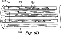
このタイプの複屈折性ポリマー繊維は、分散相繊維と呼ぶことができる。分散相繊維800の例が、図8Aに概略的に示されており、分散相802は連続相804の内部にある。端面806は、繊維800の断面を横切る分散相部分802のランダムな分布を示すための断面である。マトリックス804と分散相802との間の界面は複屈折性界面であり、したがって、偏光に敏感な反射または散乱が界面で生じる。
This type of birefringent polymer fiber can be referred to as a dispersed phase fiber. An example of a dispersed
分散相は、また、液晶小滴、液晶ポリマー、またはポリマーから形成することができる。分散相は、代わりに、空気(微小空隙)から構成することができる。いずれにせよ、分散相繊維内の分散相と連続相との間の界面は、反射偏光を含む所望の光学特性を誘起することができる。 The dispersed phase can also be formed from liquid crystal droplets, liquid crystal polymers, or polymers. The dispersed phase can alternatively be composed of air (microvoids). In any case, the interface between the disperse phase and the continuous phase within the disperse phase fiber can induce desired optical properties including reflected polarization.
複屈折性ポリマー繊維を形成するための別の方法において、第1のポリマーを充填剤として使用するが、第2および第3のポリマーを散乱繊維のために使用して、複合繊維と同様に、繊維を形成することができる。いくつかの実施形態において、第2および第3のポリマーは互いに混和性でなく、第2および第3のポリマーの少なくとも1つが複屈折性である。第2および第3のポリマーを混合し、複合繊維内の散乱繊維として押出すことができる。処理すると、第1のポリマーは複合繊維の充填剤部分を形成し、散乱繊維は、それぞれ第2および第3のポリマーからの連続相および分散相の両方を含む。このタイプの繊維は分散相複合繊維と呼ばれる。分散相複合繊維850の例が、図8Bに概略的に示されており、分散相854を含む散乱繊維852を示す。散乱繊維852は充填剤856によって囲まれる。他の実施形態において、散乱繊維は第2のポリマーおよび第3の材料から形成することができ、第3の材料は、液晶材料、液晶ポリマー、またはポリマーである。
In another method for forming birefringent polymer fibers, a first polymer is used as a filler, but second and third polymers are used for scattering fibers, similar to bicomponent fibers, Fibers can be formed. In some embodiments, the second and third polymers are not miscible with each other and at least one of the second and third polymers is birefringent. The second and third polymers can be mixed and extruded as scattering fibers within a composite fiber. Upon processing, the first polymer forms the filler portion of the composite fiber, and the scattering fibers contain both continuous and dispersed phases from the second and third polymers, respectively. This type of fiber is called a dispersed phase composite fiber. An example of a dispersed phase
同様に、同心多層繊維および非同心多層繊維は、層タイプの1つが第1のポリマーから構成され、第2の層タイプが、混和性でない2つのポリマーまたは材料の混合物から構成された交互の層から形成することができる。それらの場合において処理すると、いくつかの層が第1のポリマーを含み、いくつかの他の層が分散相および連続相の両方を含む状態で、交互の層が製造される。好ましくは、連続相および分散相の一方または両方が複屈折性である。その後の処理または配向で、第2のタイプの層内の分散相は、棒状または層状構造を呈することができる。 Similarly, concentric multilayer fibers and non-concentric multilayer fibers are alternating layers in which one of the layer types is composed of a first polymer and the second layer type is composed of a mixture of two polymers or materials that are not miscible. Can be formed from Processing in those cases produces alternating layers with some layers containing the first polymer and some other layers containing both the dispersed and continuous phases. Preferably, one or both of the continuous phase and the dispersed phase is birefringent. With subsequent processing or orientation, the dispersed phase in the second type layer can exhibit a rod-like or layered structure.
散乱繊維、または層状繊維内の複屈折性領域のサイズ要件は、さまざまな実施形態すべての間で同様である。繊維のサイズ、または多層デバイス内の層の厚さは、所望の動作波長または動作波長範囲に依存する、連続相および分散相を含む層または繊維を含むシステムの所望のサイズスケールを達成するために、適切にスケールアップまたはスケールダウンする必要がある。 The size requirements of the scattering fibers, or birefringent regions in the layered fibers, are similar among all the various embodiments. The size of the fibers, or the thickness of the layers in the multilayer device, depends on the desired operating wavelength or operating wavelength range to achieve the desired size scale of the system comprising layers or fibers comprising continuous and dispersed phases. Need to scale up or down properly.
本発明の偏光子に使用することができる別のタイプのポリマー繊維を、ここで、図9を参照して説明する。繊維はヤーン900として形成される。ヤーン900のいくつかの実施形態において、繊維は、たとえば、いくつかの多層繊維、分散相繊維、複合繊維、および/または分散相複合繊維をともに撚ることによって、ともに撚られたいくつかの複屈折性ポリマー繊維902から形成される。ヤーン900は、配向された繊維をともに撚ってヤーンを形成することによって形成することができるか、配向可能な材料から製造された等方性繊維をともに撚り、次に、ヤーン900を延伸して配向可能な材料を配向することによって、形成することができる。
Another type of polymer fiber that can be used in the polarizer of the present invention will now be described with reference to FIG. The fibers are formed as
ヤーン900は、複屈折性ポリマー繊維のみを含むことに限定されず、また、他の繊維、たとえば、等方性または複屈折性の他のポリマー材料の繊維;綿、絹、または麻などの天然繊維;および、ガラス繊維、ガラスセラミック繊維、またはセラミック繊維などの無機繊維を含むことができる。
ヤーン900は、ガラス材料、セラミック材料、および/またはガラスセラミック材料から構成された繊維または複数本の繊維を含むことができる。ガラスセラミック材料は、一般に、サイズが一般に1μmより小さい、非常に小さい結晶95〜98体積パーセントを含む。いくつかのガラスセラミック材料が、50nmの小さい結晶サイズを有し、それらを可視波長において効果的に透明にし、というのは、結晶サイズが可視光の波長よりずっと小さいからである。これらのガラスセラミックスは、また、ガラス状領域および結晶領域の屈折率の間の有効差をほとんどまたはまったく有さないことができ、それらを視覚的に透明にする。透明性に加えて、ガラスセラミック材料は、ガラスの破壊強度を超える破壊強度を有することができ、ゼロの、または値が負でさえある熱膨張係数を有することが知られている。対象となるガラスセラミックスは、Li2O−Al2O3−SiO2、CaO−Al2O3−SiO2、Li2O−MgO−ZnO−Al2O3−SiO2、Al2O3−SiO2、およびZnO−Al2O3−ZrO2−SiO2、Li2O−Al2O3−SiO2、およびMgO−Al2O3−SiO2を含むがこれらに限定されない組成物を有する。
The
いくつかのセラミックスが、また、屈折率が適切に整合したマトリックスポリマー内に埋込まれた場合、透明に見えることができるほど十分に小さい結晶サイズを有する。ミネソタ州セントポールの3Mカンパニー(3M Company,St.Paul,MN)から入手可能なネクステル(Nextel)(登録商標)セラミック(Ceramic)繊維が、このタイプの材料の例であり、すでに、糸、ヤーン、および織マットとして入手可能である。適切なセラミック材料またはガラスセラミック材料が、ガラスの化学(Chemistry of Glasses)、第2版(エー・ポール(A.Paul)、(チャップマン・アンド・ホール(Chapman and Hall)、1990年)、およびセラミックス入門(Introduction to Ceramics)、第2版(ダブリュー・ディー・キンガリー(W.D.Kingery)、ジョン・ワイリー・アンド・サンズ(John Wiley and Sons)、1976年)に、さらに記載されている。 Some ceramics also have a crystal size that is small enough to appear transparent when embedded in a matrix polymer with an appropriately matched refractive index. Nextel® Ceramic fiber available from the 3M Company of St. Paul, Minn. (3M Company, St. Paul, Minn.) Is an example of this type of material and is already a yarn, yarn And available as woven mats. Suitable ceramic materials or glass-ceramic materials are described in Chemistry of Glasses, 2nd edition (A. Paul, (Chapman and Hall, 1990), and ceramics. It is further described in Introduction to Ceramics, 2nd edition (W. D. Kingery, John Wiley and Sons, 1976).
ヤーン900は、ヤーン900の全長にわたって延在しない、一般にステープル繊維と呼ばれる複数本の繊維を含むことができる。ヤーン900はポリマーマトリックス内に封入することができ、マトリックスは、ヤーン900を構成する繊維902の間の空間を充填する。他の実施形態において、ヤーン900は繊維902間に充填剤を有することができる。
The
ヤーン900での使用のための適切な複屈折性ポリマー材料としては、PET、PENを含むポリマー、テレフタレート、ナフタレート、または両方を含むコポリマーが挙げられるが、これらに限定されない。他の方法において、ヤーン900は、ともに撚られた、多層繊維または複合繊維などの複屈折性繊維を含むことができる。
Suitable birefringent polymer materials for use in
一般に、ポリマー繊維の複屈折性界面は、細長く、繊維に沿った方向に延在する。いくつかの例示的な実施形態において、複屈折性繊維はx軸に平行にあり、したがって、拡散反射光は、ほとんど、繊維に垂直な平面、y−z平面内に散乱され、x−z平面内の散乱がほとんどない。 In general, the birefringent interface of polymer fibers is elongated and extends in a direction along the fibers. In some exemplary embodiments, the birefringent fiber is parallel to the x-axis, so diffusely reflected light is mostly scattered in a plane perpendicular to the fiber, the yz plane, and the xz plane. There is almost no scattering inside.
本発明による偏光子を製造するための1つの方法を、ここで、図10A〜10Dを参照して説明する。図10Aに概略的に示されているように、ポリマー繊維1002が第1のポリマー層1004上に置かれる。第2のポリマー層1006をポリマー繊維1002の上にキャストすることができる、図10B。第1のポリマー層1004および第2のポリマー層1006は、同じポリマー材料であることができるか、異なる材料であることができる。必要な場合、さまざまな方法、たとえば、熱および圧力、溶媒コーティングおよび乾燥、現場重合、またはそれらの組合せによって、第2のポリマー1006層を繊維1002内に浸透させることができる。
One method for manufacturing a polarizer according to the present invention will now be described with reference to FIGS. 10A-10D. As schematically shown in FIG. 10A,
繊維1002は、個別に置くことができ、個別のポリマー繊維の幅と同じまたはより大きい高さを有する繊維のスタックを構成することができるか、1つ以上のトウとして置くことができる。トウは、ともに撚られていない繊維の配列である。繊維1002は、複合繊維、多層繊維、繊維ヤーン、任意の他の適切なタイプの繊維、またはそれらの組合せであることができる。特に、1つまたは複数のトウは、互いに実質的に平行である1組の繊維を形成することができる。繊維トウ1106の実施形態が、図11に概略的に示されている。ポリマー繊維1002に支持を与えるために、および、ポリマー繊維1002をそれらの隣のものに対して所望の間隔で保つために、交差部材1108が存在することができる。たとえば、連続プロセスでポリマー繊維1002が第1のポリマー層1004の上に置かれる場合、交差部材1108は存在する必要はない。
The
繊維1002は、また、第1の層1004上に、1つ以上の織物の一部として置くことができる。織物1206が図12に概略的に示されており、ポリマー繊維1002は経糸を形成し、交差繊維1208が緯糸を形成する。交差繊維1208は、有機または無機の、任意の適切な繊維材料から製造することができ、たとえば、等方性および/または複屈折性ポリマー繊維などのポリマー繊維、または、綿、絹、および麻などの天然繊維であることができる。他の例示的な実施形態において、交差繊維1208は、上で説明されたような、ガラス繊維、たとえば、Eガラス繊維もしくはSガラス繊維、ガラスセラミック繊維、またはセラミック繊維であることができる。交差繊維が、偏光子内を通過する光に、低減された光学効果を及ぼすように、交差繊維1208の屈折率を周囲のポリマーマトリックスの屈折率に実質的に整合させることができる。さらに、経糸繊維のすべてが、複屈折性界面を含むポリマー繊維である必要はない。たとえば、経糸繊維のいくつかが、また、等方性繊維であることができ、交差繊維と同じタイプの繊維から形成することができる。いくつかの実施形態において、経糸繊維1002は、1つの特定の波長帯域内の光の1つの偏光を反射するか散乱させるのに効果的である複屈折性界面を有する繊維であることができる。交差繊維1208は、別の特定の波長帯域内の光の1つの偏光を反射するか散乱させるのに効果的な複屈折性界面を有する繊維であることができる。
The
織物は、任意の適切な織りプロセスを用いて形成することができる。たとえば、織物は、示されているような平織物、綾織物、繻子織物、またはなんらかの他の種類の織物であることができる。いくつかの例示的な実施形態において、複屈折性繊維1002は、たとえば、図13Aに部分断面で概略的に示されているように、織物内で比較的平坦である。この図が、複屈折性繊維1002が実質的にx方向に平行にあるという慣行に従うことに留意されたい。いくつかの例示的な実施形態において、複合繊維または多層繊維などのポリマー繊維は、撚られることなく、織物内の1つの配向を維持する。
The fabric can be formed using any suitable weaving process. For example, the fabric can be a plain fabric, a twill fabric, a satin fabric, or some other type of fabric as shown. In some exemplary embodiments, the
他の実施形態において、ポリマー繊維1002は、織物内で平坦である必要はない。そのような織物1206の例示的な部分断面が、図13Bに概略的に示されている。この図の見方が、図13Aの見方と異なることに留意することが重要である。図13Aは交差繊維1208の側を示し、図13Bはポリマー繊維1002の側を示す。座標軸は、先の図に用いられた慣行に従い、したがって、ポリマー繊維1002は、一般に、x軸に平行な方向にある。しかし、ポリマー繊維1002が織物1206内で起伏するので、ポリマー繊維1002の複屈折性界面は、すべて、x軸に厳密に平行にあるとは限らない。したがって、繊維1002によって反射または散乱された光を、x−z平面内に異なる角度で散乱させることができる。図において、光1302が、繊維1002にx軸に垂直な方向に入射し、光1302の一部が、光1302がポリマー繊維1002に「下方傾斜」または「上方傾斜」で入射するかに依存して、正のx方向または負のx方向の成分を有する角度αによって反射される。したがって、ポリマー繊維1002は、また、x−z平面内に反射光を拡散させることができる。x−z平面内の拡散反射度は、織物内のポリマー繊維1002の形状に依存し、ポリマー繊維1002の部分が、x方向に平行であることからそれることが大きいほど、x−z平面内の光の角度分布が大きい。
In other embodiments, the
ポリマー繊維1002は、また、不織布として、チョップドファイバーとして、またはチョップドファイバーマットとして提供することができる。
The
偏光子は、バッチプロセスで、または連続プロセスで形成することができる。連続プロセスにおいて、好ましくはトウまたは織物内の、複屈折性繊維1002は、第1のポリマー層1004上に置かれ、次に、第2のポリマー層1006を、複屈折性繊維1002の上に、連続的にキャストすることができる。次に、第2の層1006を、硬化させるか、硬化するようにすることができる。
The polarizer can be formed in a batch process or in a continuous process. In a continuous process,
必要に応じて、ポリマー繊維1002の付加的な層を、ポリマー材料のその後の層1008とともに加えることができる。たとえば、図10Cおよび図10Dは、第2のポリマー層1006の上の1組のポリマー繊維1002の追加、および第3のポリマー層1008の付与を示す。
If desired, additional layers of
第1のポリマー層1004は、熱可塑性ポリマーまたは熱硬化性タイプポリマーであることができる。第2のポリマー層1006およびその後のポリマー層1008も、熱可塑性または熱硬化性タイプポリマーであることができる。熱可塑性ポリマーを、熱および圧力、溶媒コーティングおよび乾燥、または現場重合を含むさまざまな方法によって、前のポリマー層1004に付与し、繊維1002内に浸透させることができる。熱硬化性タイプポリマーを、圧力、熱、化学線、および/または経過時間に曝すことによって、繊維1002および前のポリマー層1004および1006上にコーティングし硬化させることができる。
The
偏光子を製造するための代替方法において、特定の所望の光学特性、物理特性、または表面特性を有するポリマーフィルム1004を、上に繊維1002が置かれる基材として使用することができる。熱可塑性樹脂もしくは熱硬化性樹脂または硬化性組成物を、第2のポリマーフィルム1006として付与して、繊維1002の1つまたは複数の層に浸透させることができ、次に、第2の基材1008を付与して、繊維1002および樹脂または硬化性組成物の第2のポリマーフィルム1006の周りのサンドイッチタイプ構造を作ることができる。次に、硬化性樹脂を、硬化させるか、固めるか、反応させて、積層体を形成することができる。この場合、基材1004、1008を、熱可塑性、熱硬化性樹脂または硬化性組成物と同じ材料から製造することができるか、それを異なる材料から製造することができる。広範囲の感圧接着剤およびホットメルト接着剤を、第2の層1006のための熱可塑性樹脂もしくは熱硬化性樹脂または硬化性組成物の代わりに使用することができる。いくつかの実施形態において、第1の基材1004および第2の基材1008を、繊維1002を含む熱可塑性樹脂もしくは熱硬化性樹脂または硬化性組成物1006に密接に付着することができる。他の実施形態において、第1の基材1004および第2の基材1008は取外し可能であることができる。
In an alternative method for making a polarizer, a
複屈折性繊維の1つの層より多くを有する偏光子を製造するための別の例示的な方法において、繊維の2つ以上の層を、第1のポリマー層の上に置くことができ、次に、ポリマー材料の第2の層を、1つの工程で、ポリマーマトリックスとして繊維の上にキャストする。 In another exemplary method for producing a polarizer having more than one layer of birefringent fibers, two or more layers of fibers can be placed on the first polymer layer, and First, a second layer of polymeric material is cast onto the fibers as a polymeric matrix in one step.
複合繊維を有する偏光子を製造する別の例示的な方法において、複合繊維がポリマーマトリックス内に埋込まれる前、複合繊維の充填剤を、たとえば、溶媒に溶解することによって、除去することができる。次に、ポリマーマトリックスを、複合繊維の散乱繊維の間の充填剤として使用することができる。この方法は、複合繊維が、トウまたは織物で提供される場合、特に有用であることができる。 In another exemplary method of making a polarizer having a composite fiber, the composite fiber filler can be removed, for example, by dissolving in a solvent, before the composite fiber is embedded in the polymer matrix. . The polymer matrix can then be used as a filler between the scattering fibers of the composite fiber. This method can be particularly useful when the bicomponent fibers are provided in tow or fabric.
複合繊維を製造するための適切な方法が、複屈折性散乱繊維と、可溶性充填剤とを有する複合繊維を押出すことを含む。適切な水溶性充填剤としては、ポリビニルピロリジノン、セルロースアセテート、およびポリビニルアルコールが挙げられる。適切なポリビニルアルコールとしては、約70から95%の程度に加水分解されたポリ酢酸ビニルから製造されたものが挙げられる。 A suitable method for producing the bicomponent fibers includes extruding bicomponent fibers having birefringent scattering fibers and soluble fillers. Suitable water soluble fillers include polyvinyl pyrrolidinone, cellulose acetate, and polyvinyl alcohol. Suitable polyvinyl alcohols include those made from polyvinyl acetate hydrolyzed to the extent of about 70 to 95%.
散乱繊維は、アレイで押出し、押出されたアレイを加熱し、散乱繊維が延伸されて、所望の屈折率値をもたらす延伸比を与えるように適切な張力を加えることによって配向することができる。 The scattering fibers can be oriented by extruding with an array, heating the extruded array, and applying appropriate tension so that the scattering fibers are stretched to give a stretch ratio that provides the desired refractive index value.
複合繊維を形成する、散乱繊維の配向されたアレイを、ヤーンに形成することができる。ヤーンは、任意に、また、他のタイプの繊維を組入れることができる。ヤーンは、好ましくは、繊維のトウを形成することによって、または、繊維を織ってファブリックを形成することによって、1つの方向に配向される。押出後、任意の製造段階で、ヤーンを洗浄することによって、可溶性ポリマー充填剤を除去することができる。 An oriented array of scattering fibers that form a bicomponent fiber can be formed into the yarn. The yarn can optionally incorporate other types of fibers. The yarn is preferably oriented in one direction by forming a tow of fibers or by weaving the fibers to form a fabric. After extrusion, the soluble polymer filler can be removed by washing the yarn at any stage of production.
洗浄された散乱繊維に、流体、好ましくは硬化性樹脂流体を浸透させることができる。任意の適切な技術を用いて、樹脂を固めることができ、たとえば、樹脂を熱および/または放射線硬化させて、繊維を含むマトリックスを形成することができる。いくつかの例示的な実施形態において、樹脂は、マトリックスが平坦な表面を有するように硬化される。他の例示的な実施形態において、樹脂は、1つ以上の表面上に所望の構造を有するように硬化させることができる。たとえば、樹脂を、それが、微細複製工具の微細構造化表面と接触する表面を有する間、硬化させることができる。適切な微細構造化表面の例としては、機械加工金属表面、電鋳レプリカ、または成形ポリマーフィルムが挙げられる。マトリックス表面上に形成された適切な微細構造の例としては、線状プリズム構造、非線状プリズム構造、フレネル表面、マイクロレンズなどが挙げられる。 The washed scattering fibers can be infiltrated with a fluid, preferably a curable resin fluid. Any suitable technique can be used to harden the resin, for example, the resin can be heat and / or radiation cured to form a matrix containing fibers. In some exemplary embodiments, the resin is cured so that the matrix has a flat surface. In other exemplary embodiments, the resin can be cured to have a desired structure on one or more surfaces. For example, the resin can be cured while it has a surface that contacts the microstructured surface of the microreplication tool. Examples of suitable microstructured surfaces include machined metal surfaces, electroformed replicas, or molded polymer films. Examples of suitable microstructures formed on the matrix surface include linear prism structures, non-linear prism structures, Fresnel surfaces, microlenses, and the like.
本発明のいくつかの実施形態を、たとえば、液晶ディスプレイ(LCD)システムおよび他の偏光ディスプレイシステムに使用することができる。たとえば、上で説明されたタイプの繊維ベースの反射偏光子を使用して、LCDシステムのバックライト内のLCDパネルに伝播する光を偏光することができる。そのようなシステムとしては、LCD−TVおよびLCDモニタ、携帯電話ディスプレイ、ならびに、LCDパネルを使用して使用者に情報を表示する、デジタルスチルカメラおよびデジタルビデオカメラなどの他の電子機器が挙げられるが、これらに限定されない。 Some embodiments of the invention can be used, for example, in liquid crystal display (LCD) systems and other polarizing display systems. For example, a fiber-based reflective polarizer of the type described above can be used to polarize light that propagates to the LCD panel in the backlight of the LCD system. Such systems include LCD-TVs and LCD monitors, cell phone displays, and other electronic devices such as digital still cameras and digital video cameras that use LCD panels to display information to the user. However, it is not limited to these.
本発明は、上述された特定の実施例に限定されるとみなされるべきではないが、むしろ、特許請求の範囲に適切に記載されたような本発明の態様をすべて包含するものと理解されるべきである。本発明が適用可能であろうさまざまな変更例、均等なプロセス、および多数の構造は、本明細書を検討すると、本発明が関連する技術における当業者には容易に明らかであろう。特許請求の範囲は、そのような変更例およびデバイスを包含することが意図される。 The present invention should not be regarded as limited to the particular embodiments described above, but rather is understood to encompass all aspects of the invention as appropriately recited in the claims. Should. Various modifications, equivalent processes, and numerous structures to which the present invention may be applicable will be readily apparent to those of skill in the art to which the present invention relates upon review of the specification. The claims are intended to cover such modifications and devices.
Claims (2)
前記ポリマーマトリックス内に配置された少なくとも1つの繊維織物であって、前記繊維織物が複数のポリマー複合繊維を含み、前記ポリマー複合繊維が、第2の繊維ポリマー材料の充填剤内に配置された第1のポリマー繊維材料から形成された散乱ポリマー繊維を含み、前記第1のポリマー繊維材料が複屈折性である、少なくとも1つの繊維織物とを含む光学体。A polymer matrix comprising a matrix polymer material;
At least one fiber fabric disposed within the polymer matrix, the fiber fabric comprising a plurality of polymer composite fibers, wherein the polymer composite fibers are disposed within a filler of a second fiber polymer material. An optical body comprising scattering polymer fibers formed from one polymer fiber material, wherein the first polymer fiber material is birefringent.
Applications Claiming Priority (3)
| Application Number | Priority Date | Filing Date | Title |
|---|---|---|---|
| US11/068,590 | 2005-02-28 | ||
| US11/068,590 US7406239B2 (en) | 2005-02-28 | 2005-02-28 | Optical elements containing a polymer fiber weave |
| PCT/US2006/006386 WO2006093775A2 (en) | 2005-02-28 | 2006-02-23 | Optical elements containing a polymer fiber weave |
Publications (3)
| Publication Number | Publication Date |
|---|---|
| JP2008533514A JP2008533514A (en) | 2008-08-21 |
| JP2008533514A5 JP2008533514A5 (en) | 2009-04-09 |
| JP4950079B2 true JP4950079B2 (en) | 2012-06-13 |
Family
ID=36579449
Family Applications (1)
| Application Number | Title | Priority Date | Filing Date |
|---|---|---|---|
| JP2007558070A Expired - Fee Related JP4950079B2 (en) | 2005-02-28 | 2006-02-23 | Optical element including polymer fiber fabric |
Country Status (10)
| Country | Link |
|---|---|
| US (1) | US7406239B2 (en) |
| EP (1) | EP1853946B1 (en) |
| JP (1) | JP4950079B2 (en) |
| KR (1) | KR20070114195A (en) |
| CN (1) | CN100573197C (en) |
| AT (1) | ATE513234T1 (en) |
| MX (1) | MX2007010417A (en) |
| MY (1) | MY142311A (en) |
| TW (1) | TW200642839A (en) |
| WO (1) | WO2006093775A2 (en) |
Families Citing this family (52)
| Publication number | Priority date | Publication date | Assignee | Title |
|---|---|---|---|---|
| KR101250683B1 (en) * | 2004-03-30 | 2013-04-03 | 데이진 화이바 가부시키가이샤 | Composite fabric of island-in-sea type and process for producing the same |
| JP4671811B2 (en) * | 2004-11-05 | 2011-04-20 | 日立オートモティブシステムズ株式会社 | Finger authentication device |
| US7356231B2 (en) * | 2005-02-28 | 2008-04-08 | 3M Innovative Properties Company | Composite polymer fibers |
| US7356229B2 (en) * | 2005-02-28 | 2008-04-08 | 3M Innovative Properties Company | Reflective polarizers containing polymer fibers |
| US20060257678A1 (en) * | 2005-05-10 | 2006-11-16 | Benson Olester Jr | Fiber reinforced optical films |
| US20060257679A1 (en) * | 2005-05-10 | 2006-11-16 | Benson Olester Jr | Polymeric optical body containing inorganic fibers |
| US20070153384A1 (en) * | 2005-12-30 | 2007-07-05 | Ouderkirk Andrew J | Reinforced reflective polarizer films |
| US20070153162A1 (en) * | 2005-12-30 | 2007-07-05 | Wright Robin E | Reinforced reflective polarizer films |
| US20070236939A1 (en) * | 2006-03-31 | 2007-10-11 | 3M Innovative Properties Company | Structured Composite Optical Films |
| US20070237938A1 (en) * | 2006-03-31 | 2007-10-11 | 3M Innovative Properties Company | Reinforced Optical Films |
| US7327923B2 (en) * | 2006-03-31 | 2008-02-05 | 3M Innovative Properties Company | Spiral multilayer fibers |
| US20080274293A1 (en) * | 2006-03-31 | 2008-11-06 | 3M Innovative Properties Company | Spiral Multilayer Fibers |
| US20070236938A1 (en) * | 2006-03-31 | 2007-10-11 | 3M Innovative Properties Company | Structured Composite Optical Films |
| TW200739203A (en) * | 2006-04-10 | 2007-10-16 | Chi Lin Technology Co Ltd | Diffuser plate |
| US20070281143A1 (en) * | 2006-06-05 | 2007-12-06 | Aylward Peter T | Diffusely-reflecting element and method of making |
| US7583440B2 (en) * | 2006-06-05 | 2009-09-01 | Skc Haas Display Films Co., Ltd. | Diffusely-reflecting polarizer having nearly isotropic continuous phase |
| US7773834B2 (en) | 2006-08-30 | 2010-08-10 | 3M Innovative Properties Company | Multilayer polarizing fibers and polarizers using same |
| US20080057277A1 (en) * | 2006-08-30 | 2008-03-06 | 3M Innovative Properties Company | Polymer fiber polarizers |
| US7599592B2 (en) * | 2006-08-30 | 2009-10-06 | 3M Innovative Properties Company | Polymer fiber polarizers with aligned fibers |
| US7991257B1 (en) | 2007-05-16 | 2011-08-02 | Fusion Optix, Inc. | Method of manufacturing an optical composite |
| KR101137658B1 (en) * | 2007-06-19 | 2012-04-20 | 닛토덴코 가부시키가이샤 | Polarizing fiber, polarizing element, polarizing plate, layered optical film, and image display |
| JP5314013B2 (en) * | 2007-07-03 | 2013-10-16 | スリーエム イノベイティブ プロパティズ カンパニー | Backlight assembly having a transmissive optical film (OPTICAL FILM) |
| US7998587B2 (en) * | 2007-10-31 | 2011-08-16 | 3M Innovative Properties Company | Method of modifying light with silicone (meth)acrylate copolymers |
| KR100917434B1 (en) * | 2008-02-22 | 2009-09-14 | 순테크널로지 주식회사 | reflection type polarizing film |
| CN102016140B (en) * | 2008-03-05 | 2012-07-04 | 3M创新有限公司 | Color shifting multilayer polymer fibers and security articles containing color shifting multilayer polymer fibers |
| US8596809B2 (en) * | 2008-05-30 | 2013-12-03 | 3M Innovative Properties Company | Suspended optical film |
| US8415691B2 (en) * | 2008-08-18 | 2013-04-09 | Tsmc Solid State Lighting Ltd. | Omnidirectional reflector |
| KR100975351B1 (en) * | 2009-01-30 | 2010-08-11 | 웅진케미칼 주식회사 | Brightness enhancement film |
| JP4930540B2 (en) * | 2009-04-13 | 2012-05-16 | ソニー株式会社 | Surface light emitting device and liquid crystal display device |
| JPWO2010137450A1 (en) * | 2009-05-27 | 2012-11-12 | 株式会社ダイセル | Polarizing element and display device using the same |
| KR101666570B1 (en) * | 2009-06-15 | 2016-10-17 | 삼성디스플레이 주식회사 | Liquid crystal display apparatus and method of manufacturing the same |
| JP5520622B2 (en) * | 2010-01-29 | 2014-06-11 | 古河電気工業株式会社 | Photonic band gap fiber manufacturing method and photonic band gap fiber |
| KR101167776B1 (en) | 2010-03-30 | 2012-07-24 | 웅진케미칼 주식회사 | Brightness enhancement film |
| WO2011122794A2 (en) * | 2010-04-02 | 2011-10-06 | 웅진케미칼 주식회사 | Brightness-enhancing film |
| US8889572B2 (en) | 2010-09-29 | 2014-11-18 | Milliken & Company | Gradient nanofiber non-woven |
| US8795561B2 (en) | 2010-09-29 | 2014-08-05 | Milliken & Company | Process of forming a nanofiber non-woven containing particles |
| US8559779B2 (en) * | 2010-10-08 | 2013-10-15 | The Boeing Company | Transparent composites with organic fiber |
| WO2012166462A2 (en) | 2011-05-31 | 2012-12-06 | 3M Innovative Properties Company | Method for making microstructured tools having interspersed topographies, and articles produced therefrom |
| EP2714358B1 (en) | 2011-05-31 | 2020-02-19 | 3M Innovative Properties Company | Methods for making differentially pattern cured microstructured articles |
| EP2715415B1 (en) | 2011-05-31 | 2024-03-20 | 3M Innovative Properties Company | Retroreflective articles having composite cube-corners and methods of making |
| US20140144171A1 (en) * | 2011-06-30 | 2014-05-29 | Bha Altair, Llc | Method of Wetting Evaporative Cooler Media Through a Fabric Distribution Layer |
| CN102650715B (en) * | 2012-01-13 | 2015-04-08 | 深圳大学 | Photonic crystal waveguide TE-polarization separator |
| KR101446624B1 (en) * | 2013-07-10 | 2014-10-06 | 한국생산기술연구원 | Manufacturing method of fiber-oriented composite material and its products manufactured thereby |
| WO2015005584A1 (en) * | 2013-07-10 | 2015-01-15 | 한국생산기술연구원 | Method for manufacturing oriented-fiber composite material, oriented-fiber composite material manufactured thereby, reflective polarizing light film comprising oriented-fiber composite material, and method for manufacturing reflective polarizing light film |
| CN103994366B (en) * | 2014-05-04 | 2016-06-15 | 北京京东方视讯科技有限公司 | A kind of down straight aphototropism mode set and display device |
| KR101659819B1 (en) * | 2014-06-02 | 2016-09-27 | 한국생산기술연구원 | Reflection polarized light film improved reflectivity and backlight unit for liquid crystal display |
| JP6771951B2 (en) * | 2016-05-26 | 2020-10-21 | トヨタ紡織株式会社 | Manufacturing method of woven fabric, design woven fabric and manufacturing method of interior material |
| JP6634049B2 (en) * | 2017-06-29 | 2020-01-22 | 信越石英株式会社 | Glass cloth light reflector |
| FR3081388A1 (en) * | 2018-05-25 | 2019-11-29 | Compagnie Plastic Omnium | REINFORCED LIGHT JOINT FOR BODY COMPONENT |
| US11215752B1 (en) * | 2019-12-13 | 2022-01-04 | Apple Inc. | Electronic devices with image transport layers |
| TWI744108B (en) * | 2020-11-24 | 2021-10-21 | 勤倫有限公司 | Silk made by cutting film material and refined to improve physical properties and its production method |
| KR102605718B1 (en) * | 2023-07-04 | 2023-11-23 | 김현태 | Fabric for radiation protective clothing and its manufacturing method |
Family Cites Families (87)
| Publication number | Priority date | Publication date | Assignee | Title |
|---|---|---|---|---|
| US2403731A (en) | 1943-04-01 | 1946-07-09 | Eastman Kodak Co | Beam splitter |
| US2604817A (en) | 1948-10-14 | 1952-07-29 | Du Pont | Light polarizing composition |
| US2687673A (en) | 1949-04-04 | 1954-08-31 | Boone Philip | Textile material having oriented fibers |
| US4019844A (en) | 1973-02-26 | 1977-04-26 | Toray Industries, Inc. | Apparatus for producing multiple layers conjugate fibers |
| JPS5641234A (en) | 1979-09-10 | 1981-04-17 | Asahi Chem Ind Co Ltd | Novel molding dope composition |
| US4477522A (en) | 1983-04-11 | 1984-10-16 | Sherwood Research Corporation | Reinforcing element and method of making the same |
| US4560411A (en) | 1983-05-20 | 1985-12-24 | Bm Chemie Kunststoff Gmbh | Aggregate for concrete or mortar |
| US5059482A (en) | 1988-09-13 | 1991-10-22 | Kuraray Company, Ltd. | Composite fiber and process for producing the same |
| US4963151A (en) | 1988-12-28 | 1990-10-16 | Trustees Of The University Of Pennsylvania | Reinforced bone cement, method of production thereof and reinforcing fiber bundles therefor |
| US5047288A (en) | 1989-03-31 | 1991-09-10 | Kuraray Company Limited | Nonwoven fabric comprising single filaments and filament bundles that yield improved impact resistant molded articles |
| US5486949A (en) | 1989-06-20 | 1996-01-23 | The Dow Chemical Company | Birefringent interference polarizer |
| US5217794A (en) | 1991-01-22 | 1993-06-08 | The Dow Chemical Company | Lamellar polymeric body |
| US5251065A (en) | 1991-07-31 | 1993-10-05 | Kuraray Co., Ltd. | Polarizing screen and projector using the same |
| JP3013551B2 (en) | 1991-10-23 | 2000-02-28 | 住友化学工業株式会社 | Reflective screen |
| US5269995A (en) | 1992-10-02 | 1993-12-14 | The Dow Chemical Company | Coextrusion of multilayer articles using protective boundary layers and apparatus therefor |
| ES2161766T3 (en) | 1993-05-03 | 2001-12-16 | Minnesota Mining & Mfg | REINFORCEMENT ELEMENTS FOR MOLDABLE COMPOSITIONS PER COLADA. |
| US5389324A (en) | 1993-06-07 | 1995-02-14 | The Dow Chemical Company | Layer thickness gradient control in multilayer polymeric bodies |
| KR0142032B1 (en) | 1993-09-24 | 1998-07-01 | 마쓰오 히로또 | Polarizing screen |
| US5882774A (en) | 1993-12-21 | 1999-03-16 | Minnesota Mining And Manufacturing Company | Optical film |
| US5629055A (en) | 1994-02-14 | 1997-05-13 | Pulp And Paper Research Institute Of Canada | Solidified liquid crystals of cellulose with optically variable properties |
| JPH08226011A (en) | 1995-02-16 | 1996-09-03 | Tanaka Kikinzoku Kogyo Kk | Spinneret for producing modified cross-section fiber capable of embodying optical function |
| US5751388A (en) | 1995-04-07 | 1998-05-12 | Honeywell Inc. | High efficiency polarized display |
| US5877829A (en) | 1995-11-14 | 1999-03-02 | Sharp Kabushiki Kaisha | Liquid crystal display apparatus having adjustable viewing angle characteristics |
| US5783120A (en) | 1996-02-29 | 1998-07-21 | Minnesota Mining And Manufacturing Company | Method for making an optical film |
| BR9707766A (en) | 1996-02-29 | 1999-07-27 | Minnesota Mining & Mfg | Optical body |
| US5825543A (en) | 1996-02-29 | 1998-10-20 | Minnesota Mining And Manufacturing Company | Diffusely reflecting polarizing element including a first birefringent phase and a second phase |
| US5867316A (en) | 1996-02-29 | 1999-02-02 | Minnesota Mining And Manufacturing Company | Multilayer film having a continuous and disperse phase |
| JP3851380B2 (en) | 1996-05-16 | 2006-11-29 | グンゼ株式会社 | Light diffusing sheet and manufacturing method thereof |
| WO1998035248A1 (en) | 1997-02-11 | 1998-08-13 | Massachusetts Institute Of Technology | Polymeric photonic band gap materials |
| WO1998044367A1 (en) | 1997-03-29 | 1998-10-08 | Deutsche Telekom Ag | Fiber-integrated photon crystals and systems |
| CN1098940C (en) | 1997-04-11 | 2003-01-15 | 帝人株式会社 | Fiber having optical interference function and its use |
| EP0877103A3 (en) | 1997-04-28 | 1999-02-10 | Nissan Motor Company, Limited | Fiber structure, cloths using same, and textile goods |
| KR100312148B1 (en) | 1997-05-02 | 2001-12-12 | 하나와 요시카즈 | Fibers with Optical Function |
| US7226966B2 (en) | 2001-08-03 | 2007-06-05 | Nanogram Corporation | Structures incorporating polymer-inorganic particle blends |
| KR100324459B1 (en) | 1997-10-02 | 2002-02-27 | 하나와 요시카즈 | Fiber Structure and Textile Using Same |
| JPH11124734A (en) * | 1997-10-17 | 1999-05-11 | Teijin Ltd | Fibrous structure |
| US20010012149A1 (en) | 1997-10-30 | 2001-08-09 | Shawn-Yu Lin | Optical elements comprising photonic crystals and applications thereof |
| JPH11241223A (en) | 1997-12-25 | 1999-09-07 | Nissan Motor Co Ltd | Coloring conjugate short fiber and coloring structure binding the same fiber |
| US6531230B1 (en) | 1998-01-13 | 2003-03-11 | 3M Innovative Properties Company | Color shifting film |
| DE69917776D1 (en) | 1998-06-09 | 2004-07-08 | Crystal Fibre As Birkerod | FIBER WITH PHOTONIC BAND GAP |
| AU5002099A (en) * | 1998-07-30 | 2000-02-21 | Corning Incorporated | Method of fabricating photonic structures |
| JP2000052399A (en) | 1998-08-06 | 2000-02-22 | Mitsubishi Rayon Co Ltd | Manufacture of optical control element |
| US6139626A (en) | 1998-09-04 | 2000-10-31 | Nec Research Institute, Inc. | Three-dimensionally patterned materials and methods for manufacturing same using nanocrystals |
| US6630231B2 (en) | 1999-02-05 | 2003-10-07 | 3M Innovative Properties Company | Composite articles reinforced with highly oriented microfibers |
| JP4115030B2 (en) | 1999-02-23 | 2008-07-09 | ダイセル化学工業株式会社 | Transmission type light scattering sheet and method for producing the same |
| AU3550900A (en) * | 1999-03-30 | 2000-10-23 | Crystal Fibre A/S | Polarisation preserving optical fibre |
| US6301421B1 (en) | 1999-05-27 | 2001-10-09 | Trw Inc. | Photonic crystal fiber lasers and amplifiers for high power |
| US6498869B1 (en) | 1999-06-14 | 2002-12-24 | Xiaotian Steve Yao | Devices for depolarizing polarized light |
| JP2001031774A (en) | 1999-07-21 | 2001-02-06 | Daicel Chem Ind Ltd | Transmission-type light-scattering sheet and its production |
| US6239907B1 (en) | 1999-09-03 | 2001-05-29 | 3M Innovative Properties Company | Rear projection screen using birefringent optical film for asymmetric light scattering |
| US6433919B1 (en) | 2000-05-19 | 2002-08-13 | Wisconsin Alumni Research Foundation | Method and apparatus for wavelength conversion and switching |
| JP3365760B2 (en) | 2000-06-07 | 2003-01-14 | 帝人株式会社 | Colored structure |
| US6674949B2 (en) | 2000-08-15 | 2004-01-06 | Corning Incorporated | Active photonic crystal waveguide device and method |
| WO2002014913A1 (en) | 2000-08-15 | 2002-02-21 | Corning Incorporated | Active photonic crystal waveguide device |
| US7314751B2 (en) | 2000-10-30 | 2008-01-01 | The Charles Stark Draper Laboratory, Inc. | Fluorescence detection system including a photonic band gap structure |
| GB2384323B (en) | 2000-11-10 | 2004-12-29 | Crystal Fibre As | Microstructured optical fibres |
| US6529676B2 (en) | 2000-12-08 | 2003-03-04 | Lucent Technologies Inc. | Waveguide incorporating tunable scattering material |
| JP2002182013A (en) | 2000-12-12 | 2002-06-26 | Toray Ind Inc | Laminated light diffusing film |
| US20020130988A1 (en) | 2001-01-18 | 2002-09-19 | Crawford Gregory P. | Electrically controllable, variable reflecting element |
| EP1231488B1 (en) | 2001-02-09 | 2010-03-31 | Panasonic Corporation | Optical device |
| US20020154403A1 (en) | 2001-04-23 | 2002-10-24 | Trotter, Donald M. | Photonic crystal optical isolator |
| US20020181911A1 (en) | 2001-04-30 | 2002-12-05 | Wadsworth William John | Optical material and a method for its production |
| US7349611B2 (en) | 2001-06-08 | 2008-03-25 | Crystal Fibre A/S | Photonic bandgap fibre, and use thereof |
| JP2004522200A (en) | 2001-06-13 | 2004-07-22 | サムソン エレクトロニクス カンパニー,リミテッド | Manufacturing method of plastic optical fiber using extrusion die |
| US7272285B2 (en) | 2001-07-16 | 2007-09-18 | Massachusetts Institute Of Technology | Fiber waveguides and methods of making the same |
| US7359603B2 (en) | 2001-07-20 | 2008-04-15 | The University Of Syndey | Constructing preforms from capillaries and canes |
| JP2003119623A (en) | 2001-08-06 | 2003-04-23 | Nissan Motor Co Ltd | Structure with light reflective function |
| GB2384319A (en) | 2002-01-19 | 2003-07-23 | Marconi Optical Components Ltd | Polarisation converter for photonic crystal waveguide |
| WO2003064535A1 (en) | 2002-01-25 | 2003-08-07 | Sumitomo Bakelite Co., Ltd. | Transparent composite composition |
| DE60333984D1 (en) | 2002-01-25 | 2010-10-14 | Sumitomo Bakelite Co | TRANSPARENT COMPOSITION COMPOSITION |
| US6876796B2 (en) | 2002-01-30 | 2005-04-05 | Photon-X, Llc | Nanocomposite microresonators |
| KR100451689B1 (en) | 2002-04-30 | 2004-10-11 | 삼성전자주식회사 | Reflective display device using photonic crystal |
| JP2004125919A (en) * | 2002-09-30 | 2004-04-22 | Mitsui Chemicals Inc | Polarizing and splitting element |
| JP2004151271A (en) * | 2002-10-30 | 2004-05-27 | Nissan Motor Co Ltd | Structure having light reflection function |
| EP1420276A1 (en) | 2002-11-15 | 2004-05-19 | Alcatel | Polarization-preserving photonic crystal fibers |
| WO2004046777A1 (en) | 2002-11-21 | 2004-06-03 | Cactus Fiber Pty Ltd | Microstructured polymer signal guiding element |
| EP1595181A1 (en) | 2003-02-10 | 2005-11-16 | Koninklijke Philips Electronics N.V. | Display illumination system and manufacturing method thereof |
| US6873777B2 (en) | 2003-03-10 | 2005-03-29 | Japan Aviation Electronics Industry Limited | Two-dimensional photonic crystal device |
| US7082147B2 (en) | 2003-03-24 | 2006-07-25 | Eastman Kodak Company | Organic fiber laser system and method |
| JP2005076127A (en) * | 2003-08-29 | 2005-03-24 | Nissan Motor Co Ltd | Variable reflective functional structure |
| JP2005133028A (en) | 2003-10-31 | 2005-05-26 | Sumitomo Bakelite Co Ltd | Plastic composite transparent sheet and display element using it |
| JP2005153273A (en) | 2003-11-25 | 2005-06-16 | Nitto Denko Corp | Resin sheet, liquid crystal cell substrate, liquid crystal display device, substrate for electroluminescence display device, electroluminnescence display device and substrate for solar cell |
| US7224854B2 (en) * | 2004-02-12 | 2007-05-29 | Panorama Labs Pty. Ltd. | System, method, and computer program product for structured waveguide including polarizer region |
| US20050201715A1 (en) * | 2004-03-29 | 2005-09-15 | Panorama Flat Ltd. | System, method, and computer program product for magneto-optic device display |
| US7050686B2 (en) * | 2004-08-05 | 2006-05-23 | Nufern | Fiber optic article with inner region |
| JP2006099076A (en) * | 2004-09-01 | 2006-04-13 | Nitto Denko Corp | Polarizer, polarizing plate, optical film and image display device |
| US7362943B2 (en) | 2005-02-28 | 2008-04-22 | 3M Innovative Properties Company | Polymeric photonic crystals with co-continuous phases |
-
2005
- 2005-02-28 US US11/068,590 patent/US7406239B2/en not_active Expired - Fee Related
-
2006
- 2006-02-23 JP JP2007558070A patent/JP4950079B2/en not_active Expired - Fee Related
- 2006-02-23 CN CNB2006800100840A patent/CN100573197C/en not_active Expired - Fee Related
- 2006-02-23 WO PCT/US2006/006386 patent/WO2006093775A2/en active Application Filing
- 2006-02-23 MX MX2007010417A patent/MX2007010417A/en active IP Right Grant
- 2006-02-23 KR KR1020077022034A patent/KR20070114195A/en not_active Application Discontinuation
- 2006-02-23 AT AT06735873T patent/ATE513234T1/en not_active IP Right Cessation
- 2006-02-23 EP EP20060735873 patent/EP1853946B1/en not_active Not-in-force
- 2006-02-27 TW TW095106696A patent/TW200642839A/en unknown
- 2006-02-27 MY MYPI20060828A patent/MY142311A/en unknown
Also Published As
| Publication number | Publication date |
|---|---|
| JP2008533514A (en) | 2008-08-21 |
| KR20070114195A (en) | 2007-11-29 |
| US20060194487A1 (en) | 2006-08-31 |
| CN101151554A (en) | 2008-03-26 |
| EP1853946B1 (en) | 2011-06-15 |
| WO2006093775A2 (en) | 2006-09-08 |
| ATE513234T1 (en) | 2011-07-15 |
| WO2006093775A3 (en) | 2007-01-11 |
| TW200642839A (en) | 2006-12-16 |
| MX2007010417A (en) | 2007-10-17 |
| US7406239B2 (en) | 2008-07-29 |
| CN100573197C (en) | 2009-12-23 |
| MY142311A (en) | 2010-11-15 |
| EP1853946A2 (en) | 2007-11-14 |
Similar Documents
| Publication | Publication Date | Title |
|---|---|---|
| JP4950079B2 (en) | Optical element including polymer fiber fabric | |
| JP4805959B2 (en) | Reflective polarizer containing polymer fibers | |
| JP4856101B2 (en) | Polymer photonic crystal fiber | |
| JP5209326B2 (en) | Composite polymer fiber | |
| US20080055724A1 (en) | Optical devices containing birefringent polymer fibers |
Legal Events
| Date | Code | Title | Description |
|---|---|---|---|
| A521 | Request for written amendment filed |
Free format text: JAPANESE INTERMEDIATE CODE: A523 Effective date: 20090223 |
|
| A621 | Written request for application examination |
Free format text: JAPANESE INTERMEDIATE CODE: A621 Effective date: 20090223 |
|
| A131 | Notification of reasons for refusal |
Free format text: JAPANESE INTERMEDIATE CODE: A131 Effective date: 20110712 |
|
| A601 | Written request for extension of time |
Free format text: JAPANESE INTERMEDIATE CODE: A601 Effective date: 20111011 |
|
| A602 | Written permission of extension of time |
Free format text: JAPANESE INTERMEDIATE CODE: A602 Effective date: 20111018 |
|
| A521 | Request for written amendment filed |
Free format text: JAPANESE INTERMEDIATE CODE: A523 Effective date: 20120112 |
|
| TRDD | Decision of grant or rejection written | ||
| A01 | Written decision to grant a patent or to grant a registration (utility model) |
Free format text: JAPANESE INTERMEDIATE CODE: A01 Effective date: 20120207 |
|
| A01 | Written decision to grant a patent or to grant a registration (utility model) |
Free format text: JAPANESE INTERMEDIATE CODE: A01 |
|
| A61 | First payment of annual fees (during grant procedure) |
Free format text: JAPANESE INTERMEDIATE CODE: A61 Effective date: 20120308 |
|
| FPAY | Renewal fee payment (event date is renewal date of database) |
Free format text: PAYMENT UNTIL: 20150316 Year of fee payment: 3 |
|
| R150 | Certificate of patent or registration of utility model |
Free format text: JAPANESE INTERMEDIATE CODE: R150 |
|
| LAPS | Cancellation because of no payment of annual fees |