JP4949865B2 - Tape winding device with adhesive tape hanging mechanism - Google Patents
Tape winding device with adhesive tape hanging mechanism Download PDFInfo
- Publication number
- JP4949865B2 JP4949865B2 JP2007004140A JP2007004140A JP4949865B2 JP 4949865 B2 JP4949865 B2 JP 4949865B2 JP 2007004140 A JP2007004140 A JP 2007004140A JP 2007004140 A JP2007004140 A JP 2007004140A JP 4949865 B2 JP4949865 B2 JP 4949865B2
- Authority
- JP
- Japan
- Prior art keywords
- adhesive tape
- tape
- notch
- air
- rotating drum
- Prior art date
- Legal status (The legal status is an assumption and is not a legal conclusion. Google has not performed a legal analysis and makes no representation as to the accuracy of the status listed.)
- Active
Links
- 239000002390 adhesive tape Substances 0.000 title claims description 115
- 238000004804 winding Methods 0.000 title claims description 55
- 230000007246 mechanism Effects 0.000 title claims description 38
- 239000000853 adhesive Substances 0.000 claims description 11
- 230000001070 adhesive effect Effects 0.000 claims description 11
- 238000003825 pressing Methods 0.000 claims description 9
- 238000007665 sagging Methods 0.000 claims description 2
- 230000002093 peripheral effect Effects 0.000 description 9
- 239000004820 Pressure-sensitive adhesive Substances 0.000 description 7
- 230000009471 action Effects 0.000 description 5
- 238000000034 method Methods 0.000 description 4
- 230000000694 effects Effects 0.000 description 3
- 239000002184 metal Substances 0.000 description 2
- 230000008520 organization Effects 0.000 description 2
- 238000005096 rolling process Methods 0.000 description 2
- 238000007664 blowing Methods 0.000 description 1
- 230000008859 change Effects 0.000 description 1
- 230000003247 decreasing effect Effects 0.000 description 1
- 239000000463 material Substances 0.000 description 1
- 230000001737 promoting effect Effects 0.000 description 1
- 230000009467 reduction Effects 0.000 description 1
- 238000001179 sorption measurement Methods 0.000 description 1
- 230000002195 synergetic effect Effects 0.000 description 1
- 239000002699 waste material Substances 0.000 description 1
- XLYOFNOQVPJJNP-UHFFFAOYSA-N water Substances O XLYOFNOQVPJJNP-UHFFFAOYSA-N 0.000 description 1
Images


Landscapes
- Basic Packing Technique (AREA)
Description
本発明は、粘着テープを電線等の被結束体に巻回させる回転ドラムの切欠開口側に垂れ下げて供給する粘着テープ垂下機構を備えたテープ巻き装置に関するものである。 The present invention relates to tape winding equipment having a pressure-sensitive adhesive tape droop Organization supplies lowered sagging notch opening side of the rotary drum for winding an adhesive tape to be bundled body of the wire or the like.
図10(a)は、従来の粘着テープ垂下機構を備えたテープ巻き装置の一実施形態を示すものである(特許文献1参照)。 Fig.10 (a) shows one Embodiment of the tape winding apparatus provided with the conventional adhesive tape drooping mechanism (refer patent document 1).
このテープ巻き装置71は、粘着テープ72を螺旋状に巻いた粘着テープリール73を支持するリール支持部74と、粘着テープ72を粘着テープリール73から解いて前方に案内する複数のガイドローラ75,76と、前端のガイドローラ76から粘着テープ72をその粘着面が外側に位置するように垂れ下げて供給するケース77の開口部78と、開口部78に切欠部79の開口を位置させる回転ドラム80と、回転ドラム80を回転させる駆動機構とを備えたハンディタイプのものである。
This
粘着テープ垂下機構は、粘着テープ72の垂れ下げ部72aを支持する前端側のガイドローラ76と、ケース77の前端上部の傾斜面77aと、傾斜面77aの下側に続く開口78とで構成されている。粘着テープ72は自重でガイドローラ76から傾斜面77aを経て開口78の下側まで垂れ下げられる。
The adhesive tape hanging mechanism is composed of a front end
その状態で、図10(b)の如く複数本の束状の電線81が開口78から回転ドラム80の切欠部79内に粘着テープ72と共に挿入され、駆動機構で回転ドラム80が矢印の如く回転し、その初期段階でカッタ82で粘着テープ72が切断され、回転ドラム80の回転で粘着テープ72が電線81の外周に巻き付けられる。
In this state, as shown in FIG. 10B, a plurality of bundle-shaped
駆動機構としては、上下のラック83と、ラック83に歯合した回転ドラム外周のギヤと、ラック83を上下動させるガイド孔84と、回転ドラム80を前後移動させるエアシリンダ85とを備えている。
The drive mechanism includes an upper and
図11(a)は、従来の粘着テープ垂下機構とそれを備えたテープ巻き装置の他の形態を示すものである(特許文献2参照)。 Fig.11 (a) shows the other form of the conventional adhesive tape drooping mechanism and a tape winding apparatus provided with the same (refer patent document 2).
このテープ巻き装置50は、切欠部61を有する回転ドラム57と、回転ドラム57を回転させる駆動機構58と、テープ切断機構59,60と、粘着テープ54をテープ切断機構を経て回転ドラム側に供給する供給機構52とを備えた据え付けタイプのものである。
The
粘着テープ54は粘着面を外側(上側)に向けた状態で、傾斜状のガイド板56を経て回転ドラム57の傾斜状の切欠部61の開口61aに斜め方向から供給される。
The
図11(b)の如く、回転ドラム57の切欠部61内にはブラシ62が対向して設けられ、ブラシ62の間に束状の電線63が粘着テープ54と共に挿入され、回転ドラム57が矢印方向に回転して、ブラシ62との摩擦力で電線63の外周に粘着テープ54が巻き付けられる。
As shown in FIG. 11B, a brush 62 is provided in the
図11(a)の形態では、粘着テープ54が回転ドラム57の開口61aに斜めに供給されるが、特許文献2には、回転ドラム57の切欠部61を水平に位置した状態で粘着テープ54を自重で垂直に垂れ下げて供給する装置も提案されている。
11A, the
この場合、テープ切断機構のカッタ(59)も水平に配置され、カッタ(59)の上方にエアノズル(図示せず)が配置され、カッタ(59)に形成される間隙内に粘着テープ54をタイミング良く挿通させるために、エアノズルからエアを吹き付けるようになっている。
しかしながら、上記従来の図10の粘着テープ垂下機構を備えるテープ巻き装置71にあっては、回転ドラム80の開口78に垂れ下げた粘着テープ72が風や装置の移動等の影響で捲れ上がってケース77等に不用意に貼り付いたり、粘着テープ72同士が貼り付いたりし易く、その場合に、作業者が一々粘着テープ72の貼り付きを解かなければならず、テープ巻き作業性が低下すると共に、巻き付けが汚くなったり、粘着力が低下するという問題があった。これは図11のテープ巻き装置50において垂直に粘着テープ54を垂れ下げて供給するようにしたものにおいても同様である。
However, in the conventional
粘着テープ72,54の捲れ上がりを防ぐためには、硬めの粘着テープを使用するしかなく、それ以外でテープの貼り付きを防ぐために、例えば回転ドラム80の開口の上側のケース部分77に凹凸状の非粘着処理をした板状部材(図示せず)を配設したものがあるが、その場合でも、粘着テープ72を自重で垂れ下げて使用するために、テープ巻き装置を横方向や下方向に斜めに傾けて使用することはできなかった。テープ巻き装置を斜めに傾けて使用しようとすれば、硬めで垂れ下げ方向の変わり難い粘着テープを使用するしかなかった。
In order to prevent the
これらの問題は、電線81,63に代えて、電線を覆うコルゲートチューブ(ハーネス保護チューブ)や、電線以外の線条体等を被結束体として用いた場合でも同様に生じ得るものである。
These problems can occur in the same manner even when a corrugated tube (harness protection tube) that covers the electric wires, a wire body other than the electric wires, or the like is used as a bound body instead of the
本発明は、上記した点に鑑み、粘着テープの種類を限ることなく、粘着テープの垂れ下げ部の不用意な貼り付きを防止することができ、しかも、斜めに傾けても使用することのできる粘着テープ垂下機構を備えたテープ巻き装置を提供することを目的とする。 In view of the above-described points, the present invention can prevent inadvertent sticking of the hanging portion of the adhesive tape without limiting the type of the adhesive tape, and can be used even when tilted obliquely. and to provide a tape winding equipment having a pressure-sensitive adhesive tape droop Organization.
上記目的を達成するために、本発明の請求項1に係る粘着テープ垂下機構を備えたテープ巻き装置は、粘着テープをテープ巻き用の回転ドラムの切欠開口に沿って垂れ下げて供給する粘着テープ垂下機構を備え、該回転ドラムの該切欠開口に続く切欠部内に被結束体を該粘着テープの垂れ下げ部と共に挿入した状態で、該回転ドラムの回転で該被結束体に該粘着テープを巻回する粘着テープ垂下機構を備えたテープ巻き装置において、前記粘着テープの垂れ下げ部の粘着面である外面を噴出エアで前記切欠開口側に押すエア噴出口を該切欠開口よりも上側に備え、該垂れ下げ部の内面を該切欠開口側に吸引する吸引口を該切欠開口よりも下側に備え、該エア噴出口が該吸引口側に向けて斜め下向きに配置され、該吸引口が該エア噴出口側に向けて斜め上向きに配置されたことを特徴とする。
In order to achieve the above object, a tape winding apparatus having an adhesive tape drooping mechanism according to
上記構成により、エア噴出口から噴射された噴出エアが粘着テープの垂れ下げ部を回転ドラムの切欠開口側に押し付けることで、風やテープ巻き装置の移動等に起因する垂れ下げ部の捲れ上がりが阻止され、垂れ下げ部の粘着面が他の部位に不用意に付着することが防止される。垂れ下げ部が噴出エアで押圧されているから、垂れ下げ部を傾けても、垂れ下げ部が回転ドラムの切欠開口側から離れることはない。噴出エアで粘着テープを仮固定することで、硬めの粘着テープに限らず、柔軟性や伸長性の高い粘着テープの使用が可能となる。垂れ下げ部が噴出エアで押された状態で、電線等の被結束体が垂れ下げ部と共に回転ドラムの切欠開口(切欠部)内に挿入されて、回転ドラムの回転で被結束体に粘着テープが巻回される。 With the above configuration, the air blown from the air outlet pushes the hanging part of the adhesive tape against the notch opening side of the rotating drum, so that the hanging part swells due to wind or movement of the tape winding device. This prevents the adhesive surface of the hanging part from inadvertently adhering to other parts. Since the hanging part is pressed by the jet air, the hanging part is not separated from the notch opening side of the rotating drum even if the hanging part is tilted. By temporarily fixing the adhesive tape with the blown air, it is possible to use not only a hard adhesive tape but also an adhesive tape with high flexibility and extensibility. With the hanging part pressed by the blown air, the binding object such as an electric wire is inserted into the notch opening (notch part) of the rotating drum together with the hanging part, and the rotating drum rotates to adhere the adhesive tape to the binding object. Is wound.
上記構成により、吸引口から吸引されるエアと共に粘着テープの垂れ下げ部が吸引口に吸い寄せられ、回転ドラムの切欠開口側に保持されることで、風やテープ巻き装置の移動等に起因する垂れ下げ部の捲れ上がりが阻止され、垂れ下げ部の粘着面が他の部位に不用意に付着することが防止される。垂れ下げ部が吸引口に吸着されているから、垂れ下げ部を傾けても、垂れ下げ部が回転ドラムの切欠開口側から離れることはない。吸引作用で粘着テープを仮固定することで、硬めの粘着テープに限らず、柔軟性や伸長性の高い粘着テープの使用が可能となる。垂れ下げ部が吸引口に吸着された状態で、電線等の被結束体が垂れ下げ部と共に回転ドラムの切欠開口(切欠部)内に挿入されて、回転ドラムの回転で被結束体に粘着テープが巻回される。 With the above configuration, the hanging part of the adhesive tape is sucked to the suction port together with the air sucked from the suction port, and is held on the notch opening side of the rotary drum, so that it sags due to wind, movement of the tape winding device, etc. It is possible to prevent the lowered portion from rolling up and prevent the adhesive surface of the suspended portion from being inadvertently attached to other parts. Since the hanging part is adsorbed by the suction port, even if the hanging part is tilted, the hanging part does not leave the notch opening side of the rotating drum. By temporarily fixing the adhesive tape by suction, it is possible to use not only a hard adhesive tape but also an adhesive tape with high flexibility and extensibility. With the hanging part adsorbed to the suction port, the binding object such as an electric wire is inserted into the notch opening (notch part) of the rotating drum together with the hanging part, and the adhesive tape is attached to the binding object by the rotation of the rotating drum. Is wound.
上記構成により、エア噴出口から噴射された噴出エアが粘着テープの垂れ下げ部を回転ドラムの切欠開口側すなわち吸引口側に押しつつ、吸引口がその垂れ下げ部を確実に吸い寄せて吸着させる。エアの噴出は吸着を促進させるためのものであってもよい。エアの噴出方向は吸引口に向かう方向であることが好ましい。これにより、風やテープ巻き装置の移動等に起因する垂れ下げ部の捲れ上がりが阻止され、垂れ下げ部の粘着面が他の部位に不用意に付着することが防止される。垂れ下げ部が少なくとも吸引口に吸着されているから、垂れ下げ部を傾けても、垂れ下げ部が回転ドラムの切欠開口側から離れることはない。噴出エアと吸引作用で粘着テープを仮固定することで、硬めの粘着テープに限らず、柔軟性や伸長性の高い粘着テープの使用が可能となる。垂れ下げ部が少なくとも吸引口に吸着された状態で、電線等の被結束体が垂れ下げ部と共に回転ドラムの切欠開口(切欠部)内に挿入されて、回転ドラムの回転で被結束体に粘着テープが巻回される。 With the configuration described above, the air blown from the air jet outlet pushes the hanging portion of the adhesive tape toward the notch opening side of the rotating drum, that is, the suction port side, and the suction port surely sucks and adsorbs the hanging portion. The ejection of air may be for promoting adsorption. It is preferable that the air ejection direction is a direction toward the suction port. Thereby, the drooping of the hanging part due to wind or movement of the tape winding device is prevented, and the adhesive surface of the hanging part is prevented from inadvertently adhering to other parts. Since the hanging part is adsorbed to at least the suction port, even if the hanging part is tilted, the hanging part does not leave the notch opening side of the rotating drum. By temporarily fixing the adhesive tape with the blown air and suction action, it is possible to use not only a hard adhesive tape but also an adhesive tape with high flexibility and extensibility. With the hanging part at least attracted to the suction port, the object to be bound such as an electric wire is inserted into the notch opening (notch part) of the rotating drum together with the hanging part, and adheres to the object to be bound by the rotation of the rotating drum. The tape is wound.
上記構成により、粘着テープの垂れ下げ部が噴出エアや吸引で仮固定されて綺麗に伸ばされた状態から、被結束体と共に回転ドラムの切欠部内に確実に挿入されつつ被結束体の外周面に綺麗に且つ確実に接着される。 With the above structure, from dripping down portion of the pressure-sensitive adhesive tape is extended beautiful is temporarily fixed by jetting air or suction state, the outer peripheral surface of reliably inserted while the bundles into the notch portion of the rotary drum together with the bundling body Adhering cleanly and reliably.
請求項1記載の発明によれば、エアの噴出と吸引との相乗効果で、あるいはエアの噴出で粘着テープの吸引が確実に行われて、粘着テープの垂れ下げ部の捲れ上がりが確実に防止されるから、他部位への垂れ下がり部の不用意な接着や、垂れ下がり部自体の折返し接着等が防止され、垂れ下がり部の不用意な接着解除に要する手間や、接着解除せずに粘着テープを切除して廃却する手間や粘着テープの無駄が廃除され、回転ドラムによるテープ巻き作業がスムーズ且つ綺麗に確実に行われる。また、粘着テープの垂れ下げ部を傾けても、回転ドラムの切欠開口側から離れないから、電線等の被結束体の方向や作業者の姿勢等に応じてテープ巻き装置を傾けた状態でテープ巻きを行うことができ、テープ巻き作業性が向上する。また、粘着テープとして柔軟性や伸長性の高いもの等、種々のものを使用できるから、被結束体の種類等に応じてテープ巻き装置の汎用性が高まる。 According to the first aspect of the present invention, the adhesive tape is reliably sucked by the synergistic effect of the air ejection and suction, or by the air ejection, and the drooping of the hanging portion of the adhesive tape is surely prevented. Therefore, inadvertent adhesion of the hanging part to other parts, folding adhesion of the hanging part itself, etc. are prevented, and the adhesive tape is removed without releasing the time and effort required for inadvertent release of the hanging part. Thus, the time and effort of disposing of the tape and the waste of the adhesive tape are eliminated, and the tape winding operation by the rotating drum is smoothly and reliably performed. In addition, even if the hanging part of the adhesive tape is tilted, the tape does not move away from the notch opening side of the rotating drum, so the tape winding device is tilted according to the direction of the bound object such as the wire or the posture of the operator. Winding can be performed, and tape winding workability is improved. Moreover, since various things, such as a softness | flexibility and a high extensibility, can be used as an adhesive tape, the versatility of a tape winding apparatus increases according to the kind etc. of a to-be-bound body.
また、粘着テープの垂れ下げ部が噴出エアや吸引で綺麗に伸ばされた状態で被結束体と共に回転ドラムの切欠部内に確実に挿入されることで、被結束体の外周面に綺麗に且つ確実に接着され、巻回後のテープ巻き電線等の品質(商品価値)が高まる。 In addition, when the hanging part of the adhesive tape is neatly stretched by blown air or suction, it is securely inserted into the notch of the rotating drum together with the bundled body, so that the outer peripheral surface of the bundled body is clean and reliable. The quality (commercial value) of the tape-wrapped electric wire after winding is increased.
図1(a)(b)は、本発明に係る粘着テープ垂下機構とそれを備えたテープ巻き装置の一実施形態、図2は、同じく粘着テープ垂下機構とそれを用いたテープ巻き方法の一実施形態をそれぞれ示すものである。 1A and 1B show an embodiment of an adhesive tape hanging mechanism and a tape winding device including the same according to the present invention, and FIG. 2 shows an adhesive tape hanging mechanism and a tape winding method using the same. Each embodiment is shown.
図1(a)(b)の如く、このテープ巻き装置1は、ケース2の前側に粘着テープ垂下機構8と回転ドラム6とテープ切断機構21とを備え、ケース2の後側にテープ繰り出し機構5を備え、ケース2の中間部に、回転ドラム6やテープ切断機構21やテープ繰り出し機構5を作動させるための駆動部4を備えている。
As shown in FIGS. 1A and 1B, the
図2にも示す如く、粘着テープ垂下機構8は、ケース2の前端上部に配設されたエア噴出ノズル25と、ケース2の前端下部に配設された吸引孔26とを備えて構成されている。
As shown in FIG. 2, the adhesive
ケース2の前端部は左右の垂直な両側壁33の高さ方向中央にテーパ状の電線ガイド部34を形成して構成され、上側の両側壁33の間にエア噴出ノズル25が斜め後方下向きに配置され、ノズル25は一方の側壁33に沿ってエア供給管35として後方に配索され、エア供給管35はホース(図示せず)を介してテープ巻き装置1とは別体の図示しないコンプレッサ又は工場エア配管に接続される。
The front end portion of the
テーパ状の電線ガイド部34は両側壁33の水平な切欠部分36に続き、切欠部分36はやや後方の回転ドラム6の切欠部8に通じている。エア噴出ノズル25の先端のエア噴出口25aは切欠部分36の開口下端側を向いている。
The tapered
下側の両側壁33の間にブロック部37が配設され、ブロック部37の前端面37aは垂直に形成されて、切欠部分の開口36aと同一面に位置し、ブロック部37の後端面は傾斜面37bとして回転ドラム6の外周面に近接対向している。
A
ブロック部37に吸引孔26が斜め下向きに設けられ、ブロック部37の前端面37aに吸引孔26の吸引口26aが開口し、吸引孔26は後方の配管38を経てテープ巻き装置1とは別体の図示しない真空吸引機に接続されている。吸引孔26が斜めに形成されているから、吸引口26aは吸引孔26の断面積よりも大きく規定されている。
A
吸引口26aは粘着テープ17の幅方向に二つ設けられることが粘着テープ17の幅方向の位置ずれに対処する上で好ましい。上側のエア噴出ノズル25の突出方向に下側の吸引孔26が延びている。すなわち、エア噴出ノズル25の傾斜角度と吸引孔26の傾斜角度とは近い値となっている。
Two
粘着テープ17は粘着面を外向きにした状態で、ケース上側のガイド板40の水平面とガイド板40の前端側の湾曲面40aから、湾曲面40aの下側に近接した一対のガイドローラ41を経て、回転ドラム6の切欠部8の開口(切欠開口)8aの前方に近接して、垂直に垂れ下げられる。粘着テープ17の垂れ下げ部17aに向けて上側のエア噴出ノズル25からエア(噴出エア)42が噴出され、同時に、下側の吸引孔26内のエア43が矢印の如く真空吸引されて、エア42の噴出で粘着テープ17の垂れ下げ部17aの下側部分17a’がブロック部37の垂直な前端面37aに押し付けられ、エア43の吸引で垂れ下げ部17aの下側部分17a’がブロック部37の前端面37aに密着保持される。
The
これにより、硬めの粘着テープに限らず柔軟な粘着テープや伸長性の高い粘着テープや薄い粘着テープ等、性質や材質の異なる粘着テープ17を用いても、風やテープ巻き装置1の移動に起因する粘着テープ17の垂れ下げ部17aの捲れ上がりが確実に防止され、また、テープ巻き装置1を横(幅)方向に斜めにしたり、装置前端を下向きに傾斜させたりしても、粘着テープ17の垂れ下げ部17aがブロック部37から離れないから、所望の姿勢でテープ巻きを行うことができる。
As a result, not only a hard adhesive tape but also a flexible adhesive tape, a highly extensible adhesive tape, a thin adhesive tape, or other
エア噴出ノズル25の向きと吸引孔26の向きとがほぼ同じであるから、エア噴出ノズル25から噴射された(吹き出された)エア42が粘着テープ17の垂れ下げ部17aを回転ドラム6の切欠開口8a側(本例ではブロック部37の前端面37a)に押し付けつつ、エア42がスムーズに吸引孔26で吸引されて、垂れ下げ部17aの押し付け(密着)作用が効率良く確実に行われる。
Since the direction of the
図2において、金属製の回転ドラム6の上半側の外周に沿って金属製の円弧状の切断帯7が回動(進退)自在に配置され、切断帯7は先端にテープ押し部7aを有し、回転ドラム6の外周に沿う環状帯18(図1)の下半側の先端の固定刃18aと、テープ押し部7aとで粘着テープ17が剪断される。切断帯7はブロック部37の傾斜面37bに沿う空間39内に進入する。切断帯7と環状帯18とでテープ切断機構21が構成される。
In FIG. 2, a metal arc-shaped
図1において、回転ドラム6の切欠部8の片側又は両側には電線チャック(図示せず)が配置され、複数本の束状の電線(被結束体)33が回転ドラム6の切欠部8内に粘着テープ17と共に挿入されると同時に、チャックで把持される。切欠部8は回転ドラム6の中心よりも深く形成されている。
In FIG. 1, an electric wire chuck (not shown) is arranged on one side or both sides of the
図1において、駆動部4は、回転ドラム6を駆動する手段と、切断帯7を駆動する手段と、粘着テープ繰り出し機構5を駆動する手段とを備えている。以下に説明する駆動部4の構造はあくまでも一例であり、駆動部4の構造は必要に応じて適宜設定される。
In FIG. 1, the driving unit 4 includes means for driving the
回転ドラム6に一体に歯車9が設けられ、歯車9の上下に駆動用の一対の歯車10,11が歯合し、一対の歯車10,11はベルト12等を介してモータ13で同方向に回動され、何れか一方の歯車(10又は11)が回転ドラム6の切欠部8の位置に関係なく常時回転ドラム6を図1で反時計回りに駆動する。また、切断帯7の外周に図示しない円弧状ラック(ギヤ)が一体に設けられ、円弧状ラックに歯合した歯車14がモータ15で例えば90゜程度の角度で駆動される。各モータ13,15はケース2に固定されている。
A
粘着テープ繰り出し機構5は、粘着テープリール16を回動自在に保持する軸部27と、軸部27を設けた円形の回転板19と、回転板19の外周側に突設されたローラ柱状の一方向ベアリング20及び複数の小径のピン状のガイドローラ(図示せず)と、一方向ベアリング20の軸部22に設けられた小歯車23と、小歯車23に歯合する大径のリング状の内歯車(固定歯車)24とを備えている。
The adhesive tape feeding mechanism 5 includes a
一方向ベアリング20は反時計回りに自転し、内歯車24に沿って時計回りに公転する。粘着テープリール16とは紙筒26の外側に粘着テープ17を多数層に螺旋状に巻いたものを言う。内歯車24の裏側において軸部27の中心部に歯車(プーリ)28が固定され、歯車28に歯付きベルト29が歯合し、ベルト29は減速ベルト30を介してモータ31で駆動される。
The one-
回転板19が時計回り(公転方向)に回転し、小歯車23が内歯車24に沿って回転し、一方向ベアリング20が小歯車23と一体に回転しつつ回転板19と共に公転して、粘着テープ17をテープリール16から繰り出して(解いて)、前方のテープロック手段(図示せず)を経て回転ドラム6側へ供給する。
The rotating
テープロック手段は、例えば切断帯7の円弧状ラックを駆動する歯車14に連動するカム(図示せず)と、押さえローラ(図示せず)との間に粘着テープ17を挟むものである。テープロック手段で粘着テープ17を固定した状態で切断帯7によるテープ切断が行われる。
The tape lock means sandwiches the
図3〜図9は、上記粘着テープ垂下機構8の作用、すなわち粘着テープ垂下機構8を用いて粘着テープ17を束状の電線33に巻き付ける方法の一形態を示すものである。
3 to 9 show an embodiment of the operation of the adhesive
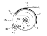
図3において、符号6は回転ドラム、18は、回転ドラム外周面に沿って位置する環状帯、7は、環状帯外周面に沿って位置する切断帯、25はエア噴出ノズル、37はブロック部、26は吸引孔、26は吸引口、41はガイドローラをそれぞれ示している。切断帯7は図2のものと較べて先端部の形状を少し変更して示している。
3,
図3において、切断帯は後退し、回転ドラム6の切欠部8が水平に位置し、切欠部8の開口8aが前側に位置している。粘着テープ17は切断帯7の先端側とガイドローラ41との間を通って下側のブロック部37の前端面に沿って垂れ下げられ、その状態で吸引孔26の真空吸引によって垂れ下げ部17aの下端部分が矢印の如く吸引口26aで吸引されている。上側のエア噴出ノズル25は作動していない。
In FIG. 3, the cutting band is retracted, the
図4の如く、テープ等で未だ結束されていない束状の電線33が作業者の手作業で粘着テープ17の垂れ下げ部17aと共に回転ドラム6の切欠部8内に挿入され、粘着テープ17の粘着面が電線33の外周面に軽く接着される。垂れ下げ部17aの下端部分は吸引口26aに密着しつつ切欠部8内に引き込まれて吸引口26aから離れる。この時点で吸引孔26のエア吸引動作は例えば切欠部8内の電線センサ(図示せず)で停止されることが好ましい。電線33は外側のチャック(図示せず)で把持される。
As shown in FIG. 4, the bundled
図4で切欠部8内の電線33が例えば電線センサ(図示せず)で検知されると、図5の如く、粘着テープ17がテープリール16(図1)から繰り出されつつ、回転ドラム6が矢印の如く反時計回りに略半回転し、電線33に粘着テープ17が略一巻きほど一次巻きされる。粘着テープ17は切欠部8から回転ドラム6の外周面と環状帯18の内周面に沿って配索される。なお、図3〜図9において、回転ドラム6と環状帯18との間には粘着テープ17を挿通させる隙間が設けられているが、図では隙間を省略している。
When the
次いで図6の如く、切断帯7が反時計回りに回動して、切断帯7の先端側のテープ押し部7aで粘着テープ17を下に押すことにより、環状帯18の下側の固定刃18aにより粘着テープ17が剪断される。なお、テープ押し部7aに刃部(可動刃)を設けてもよい。この場合、刃部(7a)を下に押すことにより、刃部(7a)で粘着テープ17を剪断する。この場合は環状帯18に刃部18aを設けずにテープ押し部を設けてもよい。切断帯7は粘着テープ17を引き出す作用と、固定刃18aとの間で粘着テープ17を切断する作用とを有する。
Next, as shown in FIG. 6, the cutting
図7の如く、テープ切断後に回転ドラムが矢印の如く反時計回りに回動し、電線の外周に粘着テープが複数巻きに二次巻きされる。切断帯7は回転ドラム6の回転中は図6のまま閉まっていることが好ましく、テープ巻き修了と同時に後退し、回転ドラム6の切欠部8が水平に位置し、切欠部8の開口8aが前側に露出される。図6のテープ切断後に切断帯7を後退させることも可能ではある。図7において、粘着テープ17の垂れ下げ部17aの下端部分はブロック部37と内側のガイド板44との間に入り込んでいるので、切断帯7の上昇(後退)時に摩擦で捲れ上がることはない。
As shown in FIG. 7, after the tape is cut, the rotating drum rotates counterclockwise as shown by an arrow, and the adhesive tape is wound around the outer periphery of the electric wire in a plurality of turns. The cutting
図8の如く、作業者がテープ巻き電線45を回転ドラム6の切欠部8から取り出し、その際に粘着テープ17の垂れ下げ部17aが捲れ上がるが、例えば切欠部8内の電線センサ(図示せず)がテープ巻き電線45の取り出しを検知して、図9の如く、上側のエア噴出ノズル25からエア42が垂れ下げ部17aに向けて矢印の如く噴射されると同時に、下側の吸引孔26でエアが矢印の如く真空吸引されて、垂れ下げ部17aの下端部分がブロック部37の吸引口26aに吸引密着される。
As shown in FIG. 8, the operator takes out the tape winding
これにより、図8における垂れ下げ部17aの大きな捲れ上がりが阻止され、垂れ下げ部17aがテープ巻き装置1等の他の部位に不用意に接着したり、垂れ下げ部17aが折り返されて相互に接着されることが確実に防止され、次の電線33(図3〜図4)のテープ巻き作業がスムーズ且つ確実に行われる。
This prevents the drooping
また、垂れ下げ部17aがブロック部37に吸着固定されるから、テープ巻き装置1(図1)を横方向に傾けたり、前下がりに傾けて使用することができ、特にハンディタイプのテープ巻き装置(図示せず)において、電線33の配索位置等に合わせてテープ巻き装置を移動や位置決め操作することができ、テープ巻き作業性が向上する。図1のテープ巻き装置1をハンディタイプにするには、駆動部4やテープ繰り出し機構を小型化すればよい。
Moreover, since the hanging
図9において、エア噴出ノズル25の動作はタイマー等で制御され、図3の次の電線待ち状態では停止している。下側のエア吸引孔26の動作のみで粘着テープ17の垂れ下げ部17aの保持を行っている。図3の待ち状態でも図9の如くエア噴出を行わせることは可能である。
In FIG. 9, the operation of the
なお、上記実施形態においては、上側のエア噴出ノズル25と下側の吸引孔26との両方を設けたが、例えば上側のエア噴出ノズル25のみ、または下側の吸引孔26のみを設けることも有効である。
In the above embodiment, both the upper
また、エア噴出口25aは環状のノズル25の先端に形成したが、ノズル25に代えて例えば吸引孔26のような噴出孔(図示せず)の先端にエア噴出口25aを形成することも可能である。この場合、下側のブロック部37と同様なブロック部(図示せず)を上側に配設し、そのブロック部に噴出孔を形成する。また、下側の吸引孔26に代えてエア噴出ノズル25のようなノズル(図示せず)を用い、その先端に吸引口26aを形成することも可能である。これらは必要に応じて適宜設定可能である。
In addition, although the
1 テープ巻き装置
6 回転ドラム
8a 切欠開口
17 粘着テープ
17a 垂れ下げ部
25a エア噴出口
26a 吸引口
33 電線(被結束体)
42 噴出エア
DESCRIPTION OF
42 Blowout air
Claims (1)
前記粘着テープの垂れ下げ部の粘着面である外面を噴出エアで前記切欠開口側に押すエア噴出口を該切欠開口よりも上側に備え、該垂れ下げ部の内面を該切欠開口側に吸引する吸引口を該切欠開口よりも下側に備え、該エア噴出口が該吸引口側に向けて斜め下向きに配置され、該吸引口が該エア噴出口側に向けて斜め上向きに配置されたことを特徴とする粘着テープ垂下機構を備えたテープ巻き装置。 An adhesive tape hanging mechanism is provided that hangs down and supplies the adhesive tape along the notch opening of the rotary drum for winding the tape , and the object to be bound is suspended in the notched portion of the rotating drum following the notch opening. In a tape winding device provided with an adhesive tape drooping mechanism that winds the adhesive tape around the bound body by the rotation of the rotating drum in the state of being inserted together,
Wherein an air spout pressing the cutout opening side outer surface an adhesive surface of the sagging down of the adhesive tape ejecting air above the notch opening, to suck the inner surface of said vertical Re lowered portion cutout opening side A suction port is provided below the notch opening , the air jet port is disposed obliquely downward toward the suction port side, and the suction port is disposed obliquely upward toward the air jet port side. A tape winding device equipped with an adhesive tape drooping mechanism.
Priority Applications (1)
| Application Number | Priority Date | Filing Date | Title |
|---|---|---|---|
| JP2007004140A JP4949865B2 (en) | 2007-01-12 | 2007-01-12 | Tape winding device with adhesive tape hanging mechanism |
Applications Claiming Priority (1)
| Application Number | Priority Date | Filing Date | Title |
|---|---|---|---|
| JP2007004140A JP4949865B2 (en) | 2007-01-12 | 2007-01-12 | Tape winding device with adhesive tape hanging mechanism |
Publications (2)
| Publication Number | Publication Date |
|---|---|
| JP2008168925A JP2008168925A (en) | 2008-07-24 |
| JP4949865B2 true JP4949865B2 (en) | 2012-06-13 |
Family
ID=39697406
Family Applications (1)
| Application Number | Title | Priority Date | Filing Date |
|---|---|---|---|
| JP2007004140A Active JP4949865B2 (en) | 2007-01-12 | 2007-01-12 | Tape winding device with adhesive tape hanging mechanism |
Country Status (1)
| Country | Link |
|---|---|
| JP (1) | JP4949865B2 (en) |
Cited By (1)
| Publication number | Priority date | Publication date | Assignee | Title |
|---|---|---|---|---|
| CN106143983A (en) * | 2016-08-12 | 2016-11-23 | 朱凌 | The frame for movement of the hand-held wrapping machine of a kind of compact and using method |
Families Citing this family (6)
| Publication number | Priority date | Publication date | Assignee | Title |
|---|---|---|---|---|
| JP6067615B2 (en) * | 2014-04-25 | 2017-01-25 | 株式会社ジーエスエレテック九州 | Automatic tape winding machine |
| CN106429579A (en) * | 2016-09-09 | 2017-02-22 | 诸暨中澳自动化设备有限公司 | Adhesive tape winding mechanism and process thereof |
| JP2018067438A (en) * | 2016-10-19 | 2018-04-26 | 住友電装株式会社 | Tape winding apparatus |
| JP2018097998A (en) * | 2016-12-12 | 2018-06-21 | 株式会社オートネットワーク技術研究所 | Tape winding device |
| CN107042899B (en) * | 2016-12-30 | 2022-09-23 | 诸暨中澳自动化设备有限公司 | Full-automatic adhesive tape winding device and process thereof |
| KR102253179B1 (en) * | 2021-03-05 | 2021-05-17 | 주식회사 동원피앤아이 | Taping device for roll string |
Family Cites Families (4)
| Publication number | Priority date | Publication date | Assignee | Title |
|---|---|---|---|---|
| JPS60163202U (en) * | 1984-03-17 | 1985-10-30 | 住友電気工業株式会社 | tying machine |
| JPH0755693B2 (en) * | 1987-03-28 | 1995-06-14 | 日東電工株式会社 | Tape binding device |
| JP2716913B2 (en) * | 1992-08-19 | 1998-02-18 | 住友電気工業株式会社 | Tape winding device for binding electric wires |
| JPH08163741A (en) * | 1994-12-06 | 1996-06-21 | Yazaki Corp | Adhesive tape winder |
-
2007
- 2007-01-12 JP JP2007004140A patent/JP4949865B2/en active Active
Cited By (1)
| Publication number | Priority date | Publication date | Assignee | Title |
|---|---|---|---|---|
| CN106143983A (en) * | 2016-08-12 | 2016-11-23 | 朱凌 | The frame for movement of the hand-held wrapping machine of a kind of compact and using method |
Also Published As
| Publication number | Publication date |
|---|---|
| JP2008168925A (en) | 2008-07-24 |
Similar Documents
| Publication | Publication Date | Title |
|---|---|---|
| JP4949865B2 (en) | Tape winding device with adhesive tape hanging mechanism | |
| TWI421176B (en) | Vehicle glazing panel cut out | |
| JP5317280B2 (en) | Protective tape peeling device | |
| KR101695607B1 (en) | Web-splicing device | |
| JP4802213B2 (en) | Adhesive seal peeling method | |
| EP1848314B1 (en) | Method and apparatus for dispensing packaging; method and apparatus for guarding machinery. | |
| JP4855950B2 (en) | Adhesive tape feeding mechanism and tape winding device equipped with the same | |
| US20120222527A1 (en) | Device And Method For Cutting Through The Adhesive Bead Of Panes That Have Been Fixed By Bonding | |
| EP1813534A1 (en) | Machine for rolling pillows or other elongated soft products | |
| WO2003032759A1 (en) | Adhesive tape for interconnecting webs used as wrapping material of rod-like article and adhesive tape feeder | |
| KR101431784B1 (en) | Unit for anti-loose tape and Winder machine of the carrier having it | |
| TWI602745B (en) | The formation of the band member fixing device | |
| JP2008155934A (en) | Labeler | |
| JP6631324B2 (en) | Mount stripping device | |
| JP4855951B2 (en) | Tape cutting mechanism, tape winding device including the same, and tape winding method | |
| JP2007106569A (en) | Interleaf peeling-off device | |
| JPH09248801A (en) | Apparatus for wrapping protective material on toothed part of circular saw | |
| JP2014084230A (en) | End folding type automatic tape cutter | |
| JP2009300566A (en) | Label and label peeling device | |
| JP5861534B2 (en) | Tape pickup apparatus and method | |
| KR101364706B1 (en) | Carrier winding method | |
| JP2009111056A (en) | Sheet peeling device and peeling method | |
| JP4328280B2 (en) | Raw film and storage and storage method thereof | |
| JP2019042967A (en) | Label processing device and label printing system | |
| JP5271684B2 (en) | Adhesive tape feeder |
Legal Events
| Date | Code | Title | Description |
|---|---|---|---|
| A621 | Written request for application examination |
Free format text: JAPANESE INTERMEDIATE CODE: A621 Effective date: 20090522 |
|
| A977 | Report on retrieval |
Free format text: JAPANESE INTERMEDIATE CODE: A971007 Effective date: 20110913 |
|
| A131 | Notification of reasons for refusal |
Free format text: JAPANESE INTERMEDIATE CODE: A131 Effective date: 20111025 |
|
| A521 | Request for written amendment filed |
Free format text: JAPANESE INTERMEDIATE CODE: A523 Effective date: 20111128 |
|
| TRDD | Decision of grant or rejection written | ||
| A01 | Written decision to grant a patent or to grant a registration (utility model) |
Free format text: JAPANESE INTERMEDIATE CODE: A01 Effective date: 20120306 |
|
| A01 | Written decision to grant a patent or to grant a registration (utility model) |
Free format text: JAPANESE INTERMEDIATE CODE: A01 |
|
| A61 | First payment of annual fees (during grant procedure) |
Free format text: JAPANESE INTERMEDIATE CODE: A61 Effective date: 20120308 |
|
| FPAY | Renewal fee payment (event date is renewal date of database) |
Free format text: PAYMENT UNTIL: 20150316 Year of fee payment: 3 |
|
| R150 | Certificate of patent or registration of utility model |
Ref document number: 4949865 Country of ref document: JP Free format text: JAPANESE INTERMEDIATE CODE: R150 Free format text: JAPANESE INTERMEDIATE CODE: R150 |
|
| R250 | Receipt of annual fees |
Free format text: JAPANESE INTERMEDIATE CODE: R250 |
|
| R250 | Receipt of annual fees |
Free format text: JAPANESE INTERMEDIATE CODE: R250 |
|
| R250 | Receipt of annual fees |
Free format text: JAPANESE INTERMEDIATE CODE: R250 |
|
| R250 | Receipt of annual fees |
Free format text: JAPANESE INTERMEDIATE CODE: R250 |
|
| R250 | Receipt of annual fees |
Free format text: JAPANESE INTERMEDIATE CODE: R250 |
|
| R250 | Receipt of annual fees |
Free format text: JAPANESE INTERMEDIATE CODE: R250 |
|
| R250 | Receipt of annual fees |
Free format text: JAPANESE INTERMEDIATE CODE: R250 |
|
| R250 | Receipt of annual fees |
Free format text: JAPANESE INTERMEDIATE CODE: R250 |
|
| R250 | Receipt of annual fees |
Free format text: JAPANESE INTERMEDIATE CODE: R250 |
|
| S531 | Written request for registration of change of domicile |
Free format text: JAPANESE INTERMEDIATE CODE: R313531 |
|
| R350 | Written notification of registration of transfer |
Free format text: JAPANESE INTERMEDIATE CODE: R350 |
|
| R250 | Receipt of annual fees |
Free format text: JAPANESE INTERMEDIATE CODE: R250 |