JP4949848B2 - Belt with variable first groove - Google Patents
Belt with variable first groove Download PDFInfo
- Publication number
- JP4949848B2 JP4949848B2 JP2006539583A JP2006539583A JP4949848B2 JP 4949848 B2 JP4949848 B2 JP 4949848B2 JP 2006539583 A JP2006539583 A JP 2006539583A JP 2006539583 A JP2006539583 A JP 2006539583A JP 4949848 B2 JP4949848 B2 JP 4949848B2
- Authority
- JP
- Japan
- Prior art keywords
- belt
- groove
- grooves
- nip load
- width
- Prior art date
- Legal status (The legal status is an assumption and is not a legal conclusion. Google has not performed a legal analysis and makes no representation as to the accuracy of the status listed.)
- Active
Links
- 239000004744 fabric Substances 0.000 claims description 39
- 239000000758 substrate Substances 0.000 claims description 25
- 239000011800 void material Substances 0.000 claims description 22
- 239000000463 material Substances 0.000 claims description 18
- 239000002952 polymeric resin Substances 0.000 claims description 17
- 238000000034 method Methods 0.000 claims description 15
- 229920003002 synthetic resin Polymers 0.000 claims description 15
- 238000009826 distribution Methods 0.000 claims description 12
- 229920001971 elastomer Polymers 0.000 claims description 5
- 238000004804 winding Methods 0.000 claims description 5
- 150000001875 compounds Chemical class 0.000 claims description 3
- 239000004745 nonwoven fabric Substances 0.000 claims 4
- 239000002861 polymer material Substances 0.000 claims 4
- 239000002759 woven fabric Substances 0.000 claims 4
- 230000007423 decrease Effects 0.000 claims 1
- 239000010410 layer Substances 0.000 description 21
- 239000011248 coating agent Substances 0.000 description 13
- 238000000576 coating method Methods 0.000 description 13
- 239000000835 fiber Substances 0.000 description 10
- XLYOFNOQVPJJNP-UHFFFAOYSA-N water Substances O XLYOFNOQVPJJNP-UHFFFAOYSA-N 0.000 description 10
- 229920005989 resin Polymers 0.000 description 8
- 239000011347 resin Substances 0.000 description 8
- 230000008859 change Effects 0.000 description 6
- 238000001035 drying Methods 0.000 description 6
- 230000008569 process Effects 0.000 description 6
- 239000000047 product Substances 0.000 description 5
- 238000000151 deposition Methods 0.000 description 4
- 238000005520 cutting process Methods 0.000 description 3
- 239000003921 oil Substances 0.000 description 3
- 238000003825 pressing Methods 0.000 description 3
- 239000007787 solid Substances 0.000 description 3
- 230000015572 biosynthetic process Effects 0.000 description 2
- 230000008020 evaporation Effects 0.000 description 2
- 238000001704 evaporation Methods 0.000 description 2
- 238000005470 impregnation Methods 0.000 description 2
- 230000001050 lubricating effect Effects 0.000 description 2
- 239000010687 lubricating oil Substances 0.000 description 2
- 238000004519 manufacturing process Methods 0.000 description 2
- 230000004048 modification Effects 0.000 description 2
- 238000012986 modification Methods 0.000 description 2
- 239000002002 slurry Substances 0.000 description 2
- 229920001059 synthetic polymer Polymers 0.000 description 2
- 238000009941 weaving Methods 0.000 description 2
- 229920003043 Cellulose fiber Polymers 0.000 description 1
- 230000008021 deposition Effects 0.000 description 1
- 239000012467 final product Substances 0.000 description 1
- 239000006260 foam Substances 0.000 description 1
- 239000007788 liquid Substances 0.000 description 1
- 239000000314 lubricant Substances 0.000 description 1
- 239000012528 membrane Substances 0.000 description 1
- 238000000465 moulding Methods 0.000 description 1
- 230000007935 neutral effect Effects 0.000 description 1
- 230000035515 penetration Effects 0.000 description 1
- 229920002635 polyurethane Polymers 0.000 description 1
- 239000004814 polyurethane Substances 0.000 description 1
- 238000004080 punching Methods 0.000 description 1
- 230000009467 reduction Effects 0.000 description 1
- 230000000284 resting effect Effects 0.000 description 1
- 239000002356 single layer Substances 0.000 description 1
- 239000002904 solvent Substances 0.000 description 1
- 238000003860 storage Methods 0.000 description 1
- 239000000126 substance Substances 0.000 description 1
- 230000032258 transport Effects 0.000 description 1
Images


Classifications
-
- D—TEXTILES; PAPER
- D21—PAPER-MAKING; PRODUCTION OF CELLULOSE
- D21F—PAPER-MAKING MACHINES; METHODS OF PRODUCING PAPER THEREON
- D21F3/00—Press section of machines for making continuous webs of paper
- D21F3/02—Wet presses
-
- D—TEXTILES; PAPER
- D21—PAPER-MAKING; PRODUCTION OF CELLULOSE
- D21F—PAPER-MAKING MACHINES; METHODS OF PRODUCING PAPER THEREON
- D21F3/00—Press section of machines for making continuous webs of paper
- D21F3/02—Wet presses
- D21F3/0209—Wet presses with extended press nip
- D21F3/0218—Shoe presses
- D21F3/0227—Belts or sleeves therefor
-
- Y—GENERAL TAGGING OF NEW TECHNOLOGICAL DEVELOPMENTS; GENERAL TAGGING OF CROSS-SECTIONAL TECHNOLOGIES SPANNING OVER SEVERAL SECTIONS OF THE IPC; TECHNICAL SUBJECTS COVERED BY FORMER USPC CROSS-REFERENCE ART COLLECTIONS [XRACs] AND DIGESTS
- Y10—TECHNICAL SUBJECTS COVERED BY FORMER USPC
- Y10S—TECHNICAL SUBJECTS COVERED BY FORMER USPC CROSS-REFERENCE ART COLLECTIONS [XRACs] AND DIGESTS
- Y10S162/00—Paper making and fiber liberation
- Y10S162/901—Impermeable belts for extended nip press
-
- Y—GENERAL TAGGING OF NEW TECHNOLOGICAL DEVELOPMENTS; GENERAL TAGGING OF CROSS-SECTIONAL TECHNOLOGIES SPANNING OVER SEVERAL SECTIONS OF THE IPC; TECHNICAL SUBJECTS COVERED BY FORMER USPC CROSS-REFERENCE ART COLLECTIONS [XRACs] AND DIGESTS
- Y10—TECHNICAL SUBJECTS COVERED BY FORMER USPC
- Y10T—TECHNICAL SUBJECTS COVERED BY FORMER US CLASSIFICATION
- Y10T428/00—Stock material or miscellaneous articles
- Y10T428/24—Structurally defined web or sheet [e.g., overall dimension, etc.]
- Y10T428/24479—Structurally defined web or sheet [e.g., overall dimension, etc.] including variation in thickness
- Y10T428/24521—Structurally defined web or sheet [e.g., overall dimension, etc.] including variation in thickness with component conforming to contour of nonplanar surface
- Y10T428/24537—Parallel ribs and/or grooves
-
- Y—GENERAL TAGGING OF NEW TECHNOLOGICAL DEVELOPMENTS; GENERAL TAGGING OF CROSS-SECTIONAL TECHNOLOGIES SPANNING OVER SEVERAL SECTIONS OF THE IPC; TECHNICAL SUBJECTS COVERED BY FORMER USPC CROSS-REFERENCE ART COLLECTIONS [XRACs] AND DIGESTS
- Y10—TECHNICAL SUBJECTS COVERED BY FORMER USPC
- Y10T—TECHNICAL SUBJECTS COVERED BY FORMER US CLASSIFICATION
- Y10T428/00—Stock material or miscellaneous articles
- Y10T428/24—Structurally defined web or sheet [e.g., overall dimension, etc.]
- Y10T428/24479—Structurally defined web or sheet [e.g., overall dimension, etc.] including variation in thickness
- Y10T428/2457—Parallel ribs and/or grooves
Description
本発明は、抄紙機において、紙製品へと処理される繊維ウェブに関する。特に、本発明は、紙の製造に関連したプレス動作用の方法及び装置に関する。 The present invention relates to a fiber web that is processed into a paper product in a paper machine. In particular, the present invention relates to a method and apparatus for pressing operations associated with paper manufacture.
製紙工程中、セルロース繊維の繊維ウェブは、抄紙機の形成部において繊維スラリーを堆積させることにより、形成ワイヤー上に形成される。形成部においてこのスラリーから大量の水が排出され、その後、新規に形成されたウェブは、プレス部へと進行される。プレス部には、一連のプレスニップが含まれ、そこで、繊維ウェブは、ウェブから水を除去するのに適用される圧縮力にさらされる。このウェブは、最終的に乾燥部へと向けられ、ここには、ウェブが向けられる周囲に加熱された乾燥ドラムが含まれる。この加熱された乾燥ドラムは、紙製品を得るように、蒸発により、ウェブの水分含量を所望のレベルにまで低減する。 During the papermaking process, a fiber web of cellulose fibers is formed on the forming wire by depositing fiber slurry in the forming section of the paper machine. A large amount of water is discharged from this slurry in the forming section, and then the newly formed web is advanced to the pressing section. The press section includes a series of press nips where the fibrous web is subjected to a compressive force applied to remove water from the web. The web is ultimately directed to the drying section, which includes a heated drying drum around which the web is directed. This heated drying drum reduces the moisture content of the web to the desired level by evaporation so as to obtain a paper product.
エネルギーコストを上昇させることは、乾燥部に侵入する前に、ウェブから出来る限り多くの水を除去するのに所望される。乾燥ドラムが蒸気によりしばしば加熱されるので、蒸気の生成に関連するコストはかなりのものであって、ウェブから大量の水を除去する必要のある場合には、特に顕著である。 Increasing energy costs is desirable to remove as much water as possible from the web before entering the drying section. Since the drying drum is often heated by steam, the costs associated with steam generation are substantial and are particularly noticeable when large amounts of water need to be removed from the web.
従来、プレス部には、隣り合う円筒形のプレスロールのペアで形成される一連のニップが含まれていた。近年、シュー型の長プレスニップを使用すると、隣り合うプレスロールで形成されるニップを使用するよりも、より有利であることが見出された。その理由は、プレスロールで形成されたニップよりも、長ニッププレスの方が、ウェブを長く通過させられるためである。ニップにおいてウェブに圧力をかけ得る時間がより長くなると、より多くの水を除去することが可能となり、従って、乾燥部において蒸発により除去すべき、ウェブに残存する水の量が少なくなる。 Conventionally, the press section includes a series of nips formed by pairs of adjacent cylindrical press rolls. In recent years, it has been found that using a shoe-type long press nip is more advantageous than using a nip formed by adjacent press rolls. The reason is that the long nip press allows the web to pass longer than the nip formed by the press roll. The longer the time during which the web can be pressurized at the nip, the more water can be removed, thus reducing the amount of water remaining on the web that must be removed by evaporation in the drying section.
本発明は、シュー型の長ニッププレスに関する。種々の長ニッププレスにおいて、ニップは、円形のプレスロールと弓状の圧力シューとの間で形成される。弓状の圧力シューは、円筒形のプレスロールに近い曲率半径を有する円筒形の曲面を有する。このロール及びシューが互いに物理的に近接すると、上述の2つのプレスロールの間で形成されるよりも、機械方向に5〜10倍長いニップが形成される。この長ニップが従来の2つのロールプレスにおけるものよりも5〜10倍長いので、この長ニップにおける繊維ウェブのいわゆるデュウェル時間(dwell time)は、2つのロールプレスで使用されるプレス力において単位平方インチ当たりの圧力が同様であっても、対応するようにより長くなる。この長ニップ技術の結果、抄紙機における従来のニップと比較して、この長ニップにおける繊維ウェブに脱水性は、劇的に増加する。 The present invention relates to a shoe-type long nip press. In various long nip presses, the nip is formed between a circular press roll and an arcuate pressure shoe. The arcuate pressure shoe has a cylindrical curved surface with a radius of curvature close to that of a cylindrical press roll. When the roll and shoe are physically close to each other, a nip that is 5 to 10 times longer in the machine direction is formed than formed between the two press rolls described above. Since this long nip is 5 to 10 times longer than in a conventional two roll press, the so-called dwell time of the fiber web in this long nip is unit square in the pressing force used in the two roll presses. Even a similar pressure per inch will be longer to accommodate. As a result of this long nip technique, the dewaterability of the fiber web in this long nip is dramatically increased compared to a conventional nip in a paper machine.
シュー型の長ニッププレスには、特許文献1に開示のような特別なベルトを必要とする。このベルトは、繊維ウェブを支持し運搬し且つ脱水するプレス布を、静止する圧力シューに対して直接摺動して接触することでもたらされる加速された摩耗から防御するように、設計される。斯かるベルトには、油の潤滑フィルム上で静止するシューに対して乗り上げ或いは摺動する平滑で不透過性の表面を設ける必要がある。ベルトは、プレス布とおよそ同程度の速度でニップを進行し、これにより、プレス布には、ベルトの表面に対して最小限の摩擦をかけることとなる。 A shoe-type long nip press requires a special belt as disclosed in Patent Document 1. This belt is designed to protect the press fabric that supports, transports and dewaters the fibrous web from the accelerated wear caused by direct sliding contact against a stationary pressure shoe. Such belts must be provided with a smooth, impermeable surface that rides or slides against a shoe resting on an oil lubricating film. The belt travels through the nip at approximately the same speed as the press fabric, which causes the press fabric to experience minimal friction against the surface of the belt.
特許文献1に開示の種々のベルトは、エンドレスループの形態をとる基礎織物を合成ポリマー樹脂に含浸して、製造される。好ましくは、この樹脂は、この基礎布を織成するヤーンが長ニッププレスの弓状の圧力シューの成分と直接接触することから防御され得るように、ベルトの少なくとも内部表面上に所望の厚みのコーティングを形成する。特に、このコーティングは、潤滑シューに対して容易に摺動するように、且つプレス布、各種布及び繊維ウェブを汚染する種々の潤滑油がベルトの構造に浸透することを阻止するように、平滑で不透過性の表面を有する必要がある。 Various belts disclosed in Patent Document 1 are manufactured by impregnating a base fabric in the form of an endless loop into a synthetic polymer resin. Preferably, the resin has a desired thickness on at least the inner surface of the belt so that the yarn woven from the base fabric can be protected from direct contact with the components of the arcuate pressure shoe of the long nip press. Form a coating. In particular, this coating is smooth so that it slides easily against the lubricating shoe and prevents the penetration of various lubricating oils that contaminate the press fabric, various fabrics and fiber webs into the belt structure. And must have an impermeable surface.
特許文献1に開示のベルトの基礎布は、単一又は多層の織成でモノフィラメントヤーンから織成されてもよく、織成部を全体的に含浸材料で含浸し得るのに十分開口するように、織成されてもよい。これにより、最終的なベルトに種々のボイドを形成する可能性を消失させる。斯かるボイドは、ベルトの間に使用される潤滑剤が通過しプレス布、各種布及び繊維ウェブを汚染することを可能とする場合がある。この基礎布は、平織りされてエンドレスな形態に継ぎ合わされてもよく、或いはチューブ状に無端で織成されてもよい。 The base fabric of the belt disclosed in Patent Document 1 may be woven from a monofilament yarn in a single or multi-layer woven, and the woven portion may be fully open so that it can be entirely impregnated with an impregnating material. , May be woven. This eliminates the possibility of forming various voids in the final belt. Such voids may allow the lubricant used between the belts to pass through and contaminate the press fabric, various fabrics and the fibrous web. The base fabric may be plain woven and seamed in an endless form, or may be woven endlessly in a tube.
上述の含浸材料を固形の状態に硬化すると、主として機械的結合により基礎布に結合され、この硬化された含浸材料は、基礎布のヤーンを取り囲む。また、硬化された含浸材料と基礎布のヤーン材料との間で種々の化学的結合又は接着性を生じる可能性もある。 When the impregnated material described above is cured to a solid state, it is bonded to the base fabric primarily by mechanical bonding, and the cured impregnated material surrounds the yarn of the base fabric. It may also cause various chemical bonds or adhesions between the cured impregnated material and the base fabric yarn material.
特許文献1に開示のような長ニッププレスベルトは、導入される長ニッププレスの寸法的な要件に依存するものであるが、エンドレスループの形態の長手方向の周囲に測定した約13〜35フィート(約4〜11メートル)の長さと、このエンドレスループの形態を横方向に横切る方向で測定した約100〜450フィート(約250〜1125センチメートル)の幅とを有する。理解されるように、斯かるベルトの製造は、合成ポリマー樹脂に含浸する前にこの基礎布がエンドレスの形態であるという要件により、複雑となっている。 A long nip press belt such as that disclosed in US Pat. No. 6,053,077, depending on the dimensional requirements of the long nip press introduced, is about 13-35 feet measured around the longitudinal circumference in the form of an endless loop. (About 4-11 meters) in length and a width of about 100-450 feet (about 250-1125 centimeters) measured transversely across this endless loop configuration. As will be appreciated, the manufacture of such belts is complicated by the requirement that the base fabric be in an endless form prior to impregnation with the synthetic polymer resin.
このベルトの外部表面上とともに内部表面上に所望の厚みの樹脂コーティングを設けることがしばしば所望される。ベルトの両側にコーティングを設けることにより、ベルトの基礎織物は、一致していない場合に、ベルトの傾斜の中立軸に近接するようになる。斯かる状況では、ベルトが抄紙機のロールやその他の類似の部材の周囲を通過して曲げられる場合に発生する内部ストレスにより、ベルトのいずれかの面から上述のコーティングを剥離させることがほとんどなくなる。 It is often desirable to provide a desired thickness of resin coating on the inner surface as well as on the outer surface of the belt. By providing a coating on both sides of the belt, the base fabric of the belt will be closer to the neutral axis of the belt's slope if it does not match. In such a situation, internal stresses that occur when the belt is bent around a paper machine roll or other similar member will rarely cause the coating described above to peel from either side of the belt. .
さらに、ベルトの外部表面が所望の厚みの樹脂コーティングを有する場合、基礎織物のいずれかの一部を曝露することなくその表面上に溝、ブラインドドリルされた孔、若しくはその他のキャビティー又はボイドを形成することが可能となる。これらの特徴は、プレスニップにおいてウェブからプレスされた水の一時的な保管場所を提供する。事実、いくつかの長ニッププレス配置に関して、溝、ブラインドドリルされた孔又はこれに類するものが設けられた種々のボイド容量をベルトの外部表面上に存在させる必要がある。 In addition, if the outer surface of the belt has a resin coating of the desired thickness, grooves, blind drilled holes, or other cavities or voids on the surface without exposing any part of the base fabric. It becomes possible to form. These features provide a temporary storage location for water pressed from the web in the press nip. In fact, for some long nip press arrangements, various void volumes provided with grooves, blind drilled holes or the like need to be present on the outer surface of the belt.
ウェブの調和(consistency)及び排出特性は、製紙工程中、出来る限り一定に保たれるように、試みられるが、変化を余儀なくされる。水分含量などのウェブの特性は、経時的に変化する可能性がある。ウェブの水分含量は、最終製品の強度や質に影響する可能性がある。例えば、機械を横切る方向(CD)における過度に変化し得る水分含量は、カール(curl)などのシートの特性が変化したり、製品の質の減少をもたらす可能性がある。従って、製紙工程中のCD方向での水分分布を制御することが必要である。
従来のベルトとは異なり、本発明によるベルトは、CD方向のシートの水分分布を修正(一定と)するように、変化するボイド容量を有する向上されたベルトを提供し得る。特に、本発明によるベルトは、例えば、ニップにおいて圧縮力をかけられるベルトの領域における深さを変えた溝を提供し得る。深さを変えたこの溝は、ベルトのCD方向における水分分布を改良し、従って、製品の質を促進する。また、本発明によるベルトは、ニップにおいて圧縮力をかけられるベルトの領域において、形状、外形寸法及び/又は寸法、幅並びに長さが変わった溝を提供し得る。さらに、本発明によるベルトは、上述の種々の変化と組み合わせてこの領域における溝の配向及び/又は数を変化し得る。 Unlike conventional belts, a belt according to the present invention may provide an improved belt with varying void volume so as to modify (constant) the moisture distribution of the sheet in the CD direction. In particular, the belt according to the invention may provide a groove of varying depth in the region of the belt which is subjected to a compressive force, for example in the nip. This groove of varying depth improves the moisture distribution in the CD direction of the belt and thus promotes product quality. Moreover, the belt according to the invention, in the region of the belt which is subjected to compressive forces at the nip, shape, external dimensions and / or dimensions may provide the unusual groove width and length. Furthermore, the belt according to the invention can change the orientation and / or number of grooves in this region in combination with the various changes described above.
従って、本発明は、製紙工程用のベルトを提供する。特に、本発明によるベルトは、ニップを共に規定する円筒形のプレスローラと弓状の圧力シューとを有するプレスが行われる長ニッププレスに使用され得る。 Accordingly, the present invention provides a belt for a papermaking process. In particular, the belt according to the invention can be used in a long nip press where a press with a cylindrical press roller and an arcuate pressure shoe together defining a nip is performed.
本発明によるベルトは、ニップ荷重領域と、2つの端部領域とを有し、このニップ荷重領域が動作中にニップを通過するように、操作され得る。本発明によるベルトは、少なくともひとつの表面上に樹脂コーティングを有する少なくともひとつの層を備え、ここで、ベルトは、長手方向又は機械方向に及ぶエンドレスループの形態である。上述の樹脂層は、ニップ荷重領域の中央部において、複数の第一溝と長手方向に実質的に平行な方向に走る複数の第二溝とを有する複数の溝を有し、この複数の第一溝は、上述の複数の第二溝とは異なる、深さ、断面形状、寸法若しくは幅又はこれらの組み合わせの少なくともひとつを有する。 The belt according to the invention has a nip load area and two end areas, which can be operated such that it passes through the nip during operation. The belt according to the invention comprises at least one layer having a resin coating on at least one surface, wherein the belt is in the form of an endless loop extending in the longitudinal or machine direction. The above-mentioned resin layer has a plurality of grooves having a plurality of first grooves and a plurality of second grooves running in a direction substantially parallel to the longitudinal direction in the central portion of the nip load region. The one groove has at least one of a depth, a cross-sectional shape, a dimension or a width, or a combination thereof different from the plurality of second grooves described above.
本発明について、下述した図面に対してなされる説明を参照して、より詳細に説明する。 The present invention will be described in more detail with reference to the description made to the drawings described below.
以下の詳細な説明は、一例であって、本発明を以下の記載にのみ限定することを意図するものではなく、添付した図面と組み合わせて、最も良好に理解されるであろう。なお、図面に記載の同じ要素については、同じ参照符号を付して示す。 The following detailed description is exemplary and is not intended to limit the invention to the following description only, but will be best understood in conjunction with the accompanying drawings. Note that the same elements described in the drawings are denoted by the same reference numerals.
本発明による好適実施例は、長ニップシュー型のプレスベルトについて、述べる。 The preferred embodiment according to the invention describes a long nip shoe type press belt.
抄紙機において紙製品に処理される繊維ウェブを脱水する長ニッププレスについて、図1に、その側方断面図を示す。プレスニップ10は、平滑な円筒形のプレスローラ12と弓状圧力シュー14とで規定される。弓状圧力シュー14は、円筒形のプレスローラ12と略同様の曲率半径を有する。円筒形のプレスローラ12と弓状圧力シュー14との間の距離は、水力手段、又はニップ10の荷重を制御するように弓状圧力シュー14に制御可能に結合された同様の手段で調節されてもよい。平滑な円筒形のプレスローラ12は、機械方向の一定のニップの圧力特性のレベルを得るように、弓状圧力シュー14に適合された制御型のクラウンロール(crown roll)であってもよい。しばしば、CD方向のシートの水分特性は、「笑顔」又は「渋面」型などを呈する。これを機械的に修正するのは、しばしば効果的ではなく、使用者を満足させるのに十分ではない。 FIG. 1 shows a side sectional view of a long nip press for dewatering a fiber web to be processed into a paper product in a paper machine. The press nip 10 is defined by a smooth cylindrical press roller 12 and an arcuate pressure shoe 14. The arcuate pressure shoe 14 has substantially the same radius of curvature as the cylindrical press roller 12. The distance between the cylindrical press roller 12 and the arcuate pressure shoe 14 is adjusted by hydraulic means or similar means controllably coupled to the arcuate pressure shoe 14 to control the load on the nip 10. May be. The smooth cylindrical press roller 12 may be a controlled crown roll adapted to the arcuate pressure shoe 14 to obtain a constant nip pressure characteristic level in the machine direction. Often, the moisture characteristics of the sheet in the CD direction are of the “smile” or “buckle” type. Correcting this mechanically is often not effective and is not sufficient to satisfy the user.
長ニッププレス型のベルト16は、ニップ10を介して閉鎖型ループの状態で延び、円筒形のプレスローラ12を弓状圧力シュー14から分離する。プレス布18と、紙シートに処理される繊維ウェブ20とは、図1の矢印で示すようにニップ10を共に通過する。繊維ウェブ20は、プレス布18で支持され、ニップ10において平滑で円筒形のプレスローラ12に直接接触する。また、繊維ウェブ20は、2つのプレス布18(二番目のプレス布は、図示せず)で挟まれたニップ10を通過してもよい。長ニッププレス型のベルト16は、矢印で示した方向にニップ10を移動する、つまり図1の時計回りに移動するが、弓状圧力シュー14にプレス布18が直接摺動接触するのを防御し、典型的には、潤滑油のフィルム上を摺動する。長ニッププレス型のベルト16は、従って、プレス布18及び繊維ウェブ20が汚染されないように、油に不透過性を示す。
A long
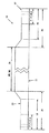
図2は、本発明の実施例によるベルトの断面図である。この図に示すように、ベルト16は、ニップ荷重領域36と、端部領域38とを有してもよい。ニップ荷重領域36は、プレスローラ12と弓状圧力シュー14との間を通過し得るベルトの領域であり、圧縮状態であってもよいベルトの領域であり、本発明に関連するベルトの領域である。端部領域38は、ベルト端部37からニップ荷重領域36へと至るベルト上の領域を規定し、当業者公知の配置を担う。ニップ荷重領域36は、ベルトの機械を横切る方向において両端上に端部領域38を有してもよい。ニップ荷重領域36及び端部領域38は、機械の走行方向又はベルトの長手方向に延びる。
FIG. 2 is a cross-sectional view of a belt according to an embodiment of the present invention. As shown in this figure, the
ベルト16は、図3に示すように、基礎構造又は基板層28などの、少なくともひとつの層を有してもよい。しかしながら、ベルト16は、追加の層を含んでもよい。基板層28は、横方向又は機械を横切る方向のヤーン30(図3の側面からみたもの)と、長手方向又は機械方向のヤーン32とを組み合わせた形態の不織構造であってもよい。なお、これらは、布を形成するように共通の交差点で共に結合されてもよい。
The
基板層28は、代替的に織成されてもよい。縦糸である横方向のヤーンは、長手方向のヤーンの上、下又はこれらの間を織成してもよい。理解されるべきことに、基板層28は、平織りであってもよく、従って継目でエンドレスの形態に結合されてもよい。さらに理解されるべきことに、基板層28は、単一の層の織成で織成されてもよく、或いは当業者に公知の他の織成パターンで織成されてもよい。
The
さらに、基板層28は、ニット織り布若しくは編み上げ布、又はGauthierによる特許文献2に開示のスパイラルリンク型のベルトであってもよい。なお、この文献を参照して、本願に取り込む。基板層28は、ポリマー樹脂材料からシート又はメンブレンの形態に成形されてもよく、これに、アパーチャを設けてもよい。また、少なくともひとつの基板層28は、Johnsonによる特許文献3に開示の不織メッシュ布を有してもよい。なお、この文献を参照して、本願に取り込む。
Further, the
さらに、基板層28は、Rexfeltらによる特許文献4に開示の方法で、織り材料、不織材料、ニット材料、編み上げ材料、成形若しくは不織メッシュ材料のストリップを螺旋巻きにして、製造されてもよい。なお、この文献を参照して、本願に取り込む。基板層28は、従って、螺旋巻きストリップを有してもよく、これらの各螺旋巻きは、長手方向に基板層28がエンドレスとなるように連続した継目で、隣り合わせて結合される。この種の層を有する長ニップ型又はシュー型のプレスベルトは、特許文献5及び6に開示されている。なお、これらの文献を参照して、本願に取り込む。
Further, the
ポリマー樹脂34などの樹脂は、ベルト16の少なくともひとつの表面上に、堆積、コーティング、含浸又はその他の堆積方法で、配置される。ポリマー樹脂34は、ベルト16の外部表面24の上、つまりベルト16が長ニッププレスに使用される際にプレス布18と接触する表面の上に、コーティング又はその他の堆積方法で、配置される。加えて、このポリマー樹脂は、ベルト16の内部表面22の上、つまりベルト16が長ニッププレスに使用される際に弓状圧力シュー14に摺動する表面の上に、コーティング又はその他の堆積方法で、配置される。また、ポリマー樹脂は、ベルト16の内部表面22及び外部表面24の両方の上にコーティングされてもよい。このポリマー樹脂は、基板層28を含浸してもよく、ベルト16に、油や水やこれらに類するものに不透過性を与えてもよい。ポリマー樹脂コーティング34は、ポリウレタンであってもよく、この固形成分を100%有してもよい。溶媒材料が完全にない100%の固形樹脂系を使用することにより、基板層28への適用の後に行われる硬化処理を通じて、このポリマー樹脂に泡の生成が回避される。他のコーティング材料を使用してもよく、例えば、ゴム又はゴム類似化合物が挙げられる。いずれにしても、これらの樹脂層は、同一であっても異なっていてもよく、硬さが同様であっても異なっていてもよい。
A resin, such as
内部表面22及び/又は外部表面24は、平滑で均一な表面を有するポリマー樹脂コーティングを提供するようにポリマー樹脂材料が硬化された後、研磨されても、磨かれてもよい。
上述のポリマー樹脂が硬化された後、ベルト16の外部表面24に溝26を設けてもよい。特に、多様な深さを持つ溝26は、ニップ荷重領域36(つまり、ベルトの全幅の一部である、圧縮がかけられるベルトの領域)に切断、穿孔又はその他の配置手段で配置されてもよく、且つ長手方向に走るように、配向されてもよい。本発明の一実施例において、溝26は、互いに平行に走るが、他の配向形態であっても、本発明に包含される。また、ポリマー樹脂が硬化される前に、切断、穿孔など、プレス型の装置で、外部表面24にプレスされてもよい。また、溝26は、(ベルト16が成型工程により製造される場合など)外部表面24に成型されてもよい。理解されるように、溝26を形成するその他の可能な方法は、当業者に明らかである。なお、本発明において、用語「溝」と称しているが、実際に起こる事象としては、取り込まれた液体を受容するように、ベルトのボイド又はボイド容量を形成することである。ベルトにおける斯かるボイド容量の変化は、「溝」の、形状、寸法、間隔及び配向並びにこれらの組み合わせを変えることで、達成され得る。
A
図3は、図2に示したニップ荷重領域36の拡大図である。図3は、また、外部表面24上の第一溝42及び第二溝44の拡大図も示す。なお、この図に付した寸法は、図示を目的とするものであって、排他的に解釈されるべきものではない。
FIG. 3 is an enlarged view of the
第一溝42及び第二溝44は、それぞれ第一深さ46及び第二深さ48を有する。また、第一溝42及び第二溝44は、第一外側幅50及び第二外側幅52をそれぞれ有するとともに、第一内側幅54及び第二内側幅56をそれぞれ有する。さらに、第一溝42及び第二溝44は、長手方向に、連続であっても、或いは不連続であってもよい。また、第一溝42及び第二溝44は、いわゆる第一島領域58及び第二島領域60により、隣り合う溝間で分割されていてもよい。第一島領域58及び第二島領域60は、ベルト16の外部表面24の機械方向に走る硬化されたポリマー樹脂の狭いピラー(pillar)と考えられてもよい。第一深さ46及び第二深さ48は、それぞれ約1.10mm及び1.5mmの値を有してもよく、第一内側幅54及び第一外側幅50は、約0.85mm及び1.18mmの値をそれぞれ有してもよく、第二内側幅56及び第二外側幅52は、約0.85mm及び1.35mmの値をそれぞれ有してもよい。第一島領域58及び第二島領域60は、約2mm及び1.88mmの幅をそれぞれ有してもよい。理解されるように、第一溝42、第二溝44、第一島領域58及び/又は第二島領域60について、その他の形状、寸法、間隔及び配向を利用してもよく、これらは、本発明に包含される。
The
図3に示すように、ニップ荷重領域36は、中央部64、中間部66及び外側部62を含んでもよい。中央部64、中間部66及び外側部62の溝26は、異なる寸法、配向、形状及び/若しくは深さ又はこれらの組み合わせを有してもよい。例えば、中央部64は、単一の幅と深さの溝を含んでもよい;また、これは、複数の第一溝42と、複数の第二溝44とを含んでもよい。中央部64における溝は、種々の様式で配列されてもよい。つまり、斯かる溝の配列は、第一溝42と、この後に第二溝44と、この後に第一溝42などの順序であってもよく、或いは複数の第一溝と、この後に複数の第二溝と、この後に複数の第一溝などの順序であってもよい。さらに、中央部64は、2つ以上の異なる、寸法、配向、形状及び/又は深さを有する溝を含んでもよく、これらの組み合わせを含んでもよい。また、中間部66及び外側部62のいずれか一方又は両方は、異なる、寸法、形状及び/又は深さを有する溝を含んでもよく、上述の通りの種々の様式で配列されてもよい。さらに、外側部62又は中間部66は、ニップ荷重領域36の一方の端部から他の端部まで、異なる形状の溝を有してもよい。
As shown in FIG. 3, the
例えば、中間部66は、ステップワイズに異なる深さの溝を含んでもよい。図3に示すように、中間部66は、位置72において約1.4mmなる初期の深さを有する溝を含み、位置71において約1.3mmなる深さの溝を含み、且つ位置70において1.2mmなる深さを有する溝を含むなど、全460mmに渡って0.10mmずつ増加する深さを有する溝を含んでもよい。斯かる配列は、中央部64に約1.5mmの深さの溝を有し外側部に1.1mmの深さの溝を有する実施例に特に有用である。これにより、外側部62へと減少し中央部64においてボイド容量が増加するという結果を本質的にもたらす。要するに、これらの溝の配列および特性は、外側部においてより溝の深さが短く中央部64へと深さが大きく変わるという、典型的な、現存するCD方向への水分分布を一定或いは向上するように、最適化されてもよい。なお、調節される水分分布に応じて、溝を有さない、或いはゼロの深さを有する溝の領域が含まれてもよい。
For example, the
図3に示すような断面形状を有し切断又は形成により設けられるように溝について述べてきたが、本発明は、これらの態様に限定されるものではない。例えば、溝は、他の断面形状を有してもよく、他の手段で得られてもよい。例として、溝26は、螺旋状、又は実質的に長手方向に進む時計回り若しくは反時計回りにおけるベルトの外周に沿った周囲に配向する溝を切断又は形成する切断装置(例えば、穿孔型の装置)で、設けられてもよい。斯かる状況において、溝は、種々の組み合わせに配列されてもよい。一配列において、時計回りに螺旋状の断面を有するひとつの溝を有し、この後に反時計回りに螺旋状の断面を有する溝を有し、その後に時計回りに螺旋状の断面を有する溝を有するなどの配列であってもよい。さらに、溝26のそれぞれは、長手方向に完全に平行でなくてもよく、若干変化するものであってもよい。また、複数の溝26は、長手方向に平行な線に対して一定の角度(例えば、45°以下)を形成する方向に走るように、配向されてもよい。
Although the groove has been described so as to have a cross-sectional shape as shown in FIG. 3 and provided by cutting or forming, the present invention is not limited to these embodiments. For example, the grooves may have other cross-sectional shapes and may be obtained by other means. By way of example, the
本質的に、本発明の原理は、例えばより小さい利用可能なボイド容量を有する領域がより少ない水を受容し得るように、上述の領域(2つの端部領域と中央領域)において溝のボイド容量を変えることを包含する。例えば、典型的な「渋面」型のCD方向におけるシートの水分分布において、シートの端部は、シートの中央よりも、より乾燥される。ベルトの2つの端部領域のボイド容量を低減することにより、これらの領域におけるシートからは、より少量の水が除かれることとなる。なぜなら、プレスニップを脱出するこのシートの水分分布は、一定となるためである。同様に、典型的な「笑顔」型のCD方向におけるシートの水分分布に関しては、ボイド容量は、上述とは逆となる。 In essence, the principle of the present invention is that the void volume of the grooves in the above-mentioned regions (two end regions and the central region), for example so that regions with smaller available void volumes can accept less water. Including changing. For example, in a typical “buckle surface” type of CD moisture distribution in the CD direction, the edge of the sheet is more dry than the center of the sheet. By reducing the void volume at the two end regions of the belt, less water is removed from the sheets in these regions. This is because the moisture distribution of this sheet that escapes from the press nip is constant. Similarly, with respect to the moisture distribution of the sheet in a typical “smile” type CD direction, the void volume is the reverse of the above.
上述の事項に対する改変は、本技術分野における当業者に明らかであるが、これらの改変は、添付した特許請求の範囲を越えるように本発明を改変するものではない。 Modifications to the above will be apparent to those skilled in the art, but these modifications do not alter the invention beyond the scope of the appended claims.
10 ニップ
12 プレスローラ
14 弓状圧力シュー
16 ベルト
18 プレス布
20 繊維ウェブ
22 内部表面
24 外部表面
26 溝
28 基板層
30 ヤーン
32 ヤーン
34 コーティング
36 ニップ荷重領域
37 ベルト端部
38 端部領域
42 第一溝
44 第二溝
46 第一深さ
48 第二深さ
50 第一外側幅
52 第二外側幅
54 第一内側幅
56 第二内側幅
58 第一島領域
60 第二島領域
62 外側部
64 中央部
66 中間部
70 位置
71 位置
72 位置
DESCRIPTION OF SYMBOLS 10 Nip 12 Press roller 14
Claims (24)
当該ベルトは、機械を横切る方向の幅を有するニップ荷重領域を有し、
当該ベルトは、動作中、前記ニップ荷重領域を有する当該ベルトが前記ニップを通過するように、動作可能であり、
当該ベルトは:
基板と;
該基板の少なくとも一つの側面上に少なくとも一つのコーティングされた層と;
溝を含む前記層における所望のパターンと;
を有し、
前記の所望のパターンは、前記ニップ荷重領域が該ニップ荷重領域の幅を横切るようなボイド容量を有するとともに、前記ボイド容量を変化させ、それによって機械を横断する方向のシートの水分分布を修正することができるように、異なる幅の組み合わせ、異なる断面形状の組み合わせ、異なる間隔の組み合わせの中の一つ以上の組み合わせという属性を持つ、または、それに加えて、異なる深さの組み合わせという更なる属性を持つ複数の溝によって、前記ボイド容量が生じているパターンであることを特徴とするベルト。An endless belt for use in a shoe-type press having a cylindrical press roll that defines both nips and an arcuate pressure shoe,
The belt has a nip load area having a width in a direction across the machine;
The belt is operable so that, during operation, the belt having the nip load region passes through the nip;
The belt is:
A substrate;
At least one coated layer on at least one side of the substrate;
A desired pattern in the layer including grooves;
Have
The desired pattern has a void volume such that the nip load area traverses the width of the nip load area and changes the void volume, thereby modifying the moisture distribution of the sheet in the direction across the machine. as can have a combination of different width, a combination of different cross-sectional shapes, an attribute called one or more combinations of the combinations of the different intervals, or in addition to, made further that combination of different depths A belt in which the void capacity is generated by a plurality of grooves having attributes.
該2つの外側部のそれぞれは、中央部の側方に配置されていることを特徴とする請求項1に記載のベルト。The nip load area includes two outer portions,
The belt according to claim 1, wherein each of the two outer portions is disposed on a side of a central portion.
該2つの中間部のそれぞれは、前記中央部の側方に配置され、且つ前記中央部と前記外側部との間に配置されていることを特徴とする請求項2に記載のベルト。The nip load region includes two intermediate portions;
3. The belt according to claim 2, wherein each of the two intermediate portions is disposed on a side of the central portion and is disposed between the central portion and the outer portion.
前記の巻きは、連続する継目により隣り合う巻きに結合されており、
前記のストリップの材料は、織布、不織布、ニット布、編み上げ布、ポリマー材料と不織メッシュ布との成形シート、及びスパイラルリンクベルトからなる群から選択されることを特徴とする請求項1に記載のベルト。The substrate is a strip of material spirally wound in a plurality of turns,
The windings are connected to adjacent windings by continuous seams,
The material of the strip is selected from the group consisting of a woven fabric, a nonwoven fabric, a knitted fabric, a knitted fabric, a molded sheet of a polymer material and a non-woven mesh fabric, and a spiral link belt. The belt described.
該繰り返しのパターンは、第一の幅と第一深さとを有する第一溝の隣に、第二の幅と第二深さとを有する第二溝があり、さらにその隣に、前記第一の幅と前記第一深さとを有する前記第一溝があるなどのパターンであることを特徴とする請求項1に記載のベルト。The grooves are formed in a repeating pattern with different widths and depths,
The repeating pattern includes a second groove having a second width and a second depth adjacent to the first groove having a first width and a first depth, and further adjacent to the second groove. The belt according to claim 1, wherein the belt has a pattern such as the first groove having a width and the first depth.
基板の少なくともひとつの表面上にコーティングされた層を有する基板を設けるステップと;
溝を含む前記層に所望のパターンを形成するステップと;
ボイド容量が変わるように、前記ニップ荷重領域が該ニップ荷重領域の幅を横切ってボイド容量を有するとともに、異なる幅の組み合わせ、異なる断面形状の組み合わせ、若しくは異なる間隔の組み合わせの中の一つ以上の組み合わせという属性を持つ、または、それに加えて異なる深さの組み合わせという更なる属性を持つ複数の溝によって、前記ボイド容量がもたらされるように、前記の所望のパターンを生成するステップであって、機械を横切る方向のシートの水分分布を修正する、ステップと;
を有することを特徴とする方法。A method for adjusting the moisture distribution of a shoe-type press belt comprising:
Providing a substrate having a coated layer on at least one surface of the substrate;
Forming a desired pattern in the layer including grooves;
As void volume is changed, the conjunction nip load region has a void volume across the width of the nip load area, the combination of different widths, different combinations of cross-sectional shapes, or different spacing one or more of the combination of contains the attribute combinations of, or by a plurality of grooves having a further attribute depth combination of different Additionally, the so void volume is cod also, in the step of generating a desired pattern of the Correcting the moisture distribution of the sheet in the direction across the machine; and
A method characterized by comprising:
前記の巻きは、連続する継目により隣り合う巻きに結合されており、
前記のストリップの材料は、織布、不織布、ニット布、編み上げ布、ポリマー材料と不織メッシュ布との成形シート、及びスパイラルリンクベルトからなる群から選択されることを特徴とする請求項16に記載の方法。The substrate is a strip of material spirally wound in a plurality of turns,
The windings are connected to adjacent windings by continuous seams,
The material of the strip is selected from the group consisting of a woven fabric, a nonwoven fabric, a knitted fabric, a knitted fabric, a molded sheet of a polymer material and a non-woven mesh fabric, and a spiral link belt. The method described.
当該ベルトは、機械を横切る方向の幅を有するニップ荷重領域を有し、
当該ベルトは、動作中、前記ニップ荷重領域を有する当該ベルトが前記ニップを通過するように、動作可能であり、
当該ベルトは:
基板と;
該基板の少なくとも一つの側面上に少なくとも一つのコーティングされた層と;
溝を含む前記層における所望のパターンと;
を有し、
前記の所望のパターンは、前記ニップ荷重領域が該ニップ荷重領域の幅を横切るようなボイド容量を有するとともに、前記ニップ荷重領域の中央部におけるボイド容量が前記ニップ荷重領域の外側部におけるボイド容量よりも大きくなるように前記ボイド容量を変化させることができるように、異なる幅の組み合わせ、異なる断面形状の組み合わせ、異なる間隔の組み合わせの中の一つ以上の組み合わせという属性を持つ、または、それに加えて、異なる深さの組み合わせという更なる属性を持つ複数の溝によって、前記ボイド容量が生じているパターンであり、
前記幅の組み合わせ、断面形状の組み合わせ、間隔の組み合わせの中の一つ以上の組み合わせ、または、それに加えて深さの組み合わせは、前記ボイド容量を調整し、それによって機械に直交する方向のシートの水分分布を修正することができるように、場所によって変化することを特徴とするベルト。An endless belt for use in a shoe-type press having a cylindrical press roll that defines both nips and an arcuate pressure shoe,
The belt has a nip load area having a width in a direction across the machine;
The belt is operable so that, during operation, the belt having the nip load region passes through the nip;
The belt is:
A substrate;
At least one coated layer on at least one side of the substrate;
A desired pattern in the layer including grooves;
Have
The desired pattern has a void capacity such that the nip load area crosses the width of the nip load area, and a void capacity at a central portion of the nip load area is larger than a void capacity at an outer portion of the nip load area. as can be changed the void volume as is also increased, with a combination of different width, a combination of different cross-sectional shapes, an attribute called one or more combinations of the combinations of the different intervals, or, it in addition, a by a plurality of grooves with additional attributes that combination of different depths, the void volume is generated patterns,
The combination of the width, the combination of the cross-sectional shape, one or more combinations of the combinations of intervals or a combination of depth in addition, by adjusting the void volume, thereby the direction of the sheet perpendicular to the machine A belt characterized in that it varies from place to place so that the moisture distribution can be corrected.
Applications Claiming Priority (3)
| Application Number | Priority Date | Filing Date | Title |
|---|---|---|---|
| US51678603P | 2003-11-03 | 2003-11-03 | |
| US60/516,786 | 2003-11-03 | ||
| PCT/US2004/036269 WO2005042835A1 (en) | 2003-11-03 | 2004-11-01 | Belt with variable grooves |
Publications (3)
| Publication Number | Publication Date |
|---|---|
| JP2007510826A JP2007510826A (en) | 2007-04-26 |
| JP2007510826A5 JP2007510826A5 (en) | 2010-09-09 |
| JP4949848B2 true JP4949848B2 (en) | 2012-06-13 |
Family
ID=34549569
Family Applications (1)
| Application Number | Title | Priority Date | Filing Date |
|---|---|---|---|
| JP2006539583A Active JP4949848B2 (en) | 2003-11-03 | 2004-11-01 | Belt with variable first groove |
Country Status (13)
| Country | Link |
|---|---|
| US (1) | US7384516B2 (en) |
| EP (1) | EP1682718A1 (en) |
| JP (1) | JP4949848B2 (en) |
| KR (1) | KR101051669B1 (en) |
| CN (1) | CN1875148B (en) |
| AU (1) | AU2004286319A1 (en) |
| BR (1) | BRPI0416124B1 (en) |
| CA (1) | CA2544515A1 (en) |
| NO (1) | NO20062522L (en) |
| RU (1) | RU2384663C2 (en) |
| TW (1) | TWI338070B (en) |
| WO (1) | WO2005042835A1 (en) |
| ZA (1) | ZA200604530B (en) |
Families Citing this family (10)
| Publication number | Priority date | Publication date | Assignee | Title |
|---|---|---|---|---|
| JP5412028B2 (en) * | 2006-12-22 | 2014-02-12 | ヤマウチ株式会社 | Shoe press belt |
| JP4477025B2 (en) * | 2007-03-12 | 2010-06-09 | イチカワ株式会社 | Shoe press belt for papermaking |
| DE102007025816A1 (en) * | 2007-06-02 | 2008-12-04 | Voith Patent Gmbh | roll shell |
| DE102007047880A1 (en) | 2007-11-28 | 2009-06-10 | Voith Patent Gmbh | Belt, particularly endless belt for web-processing machine, is designed in units made of synthetic filament yarns, which represent monofilament yarns |
| JP2010196205A (en) * | 2009-02-26 | 2010-09-09 | Ichikawa Co Ltd | Shoe press belt |
| DE102011004565A1 (en) * | 2011-02-23 | 2012-08-23 | Voith Patent Gmbh | Press section of a machine for producing a fibrous web |
| US9481777B2 (en) | 2012-03-30 | 2016-11-01 | The Procter & Gamble Company | Method of dewatering in a continuous high internal phase emulsion foam forming process |
| FI20156030A (en) * | 2015-12-30 | 2017-07-01 | Valmet Technologies Oy | Press band, long nip arrangement and method for producing a press band |
| DE202016103702U1 (en) | 2016-07-11 | 2016-08-03 | Cheng-Chuan YANG | Eye Massager |
| CN112522984B (en) * | 2020-12-17 | 2022-06-07 | 淄博泰鼎机械科技有限公司 | Shoe type presser |
Family Cites Families (29)
| Publication number | Priority date | Publication date | Assignee | Title |
|---|---|---|---|---|
| FR2494318B1 (en) | 1980-11-14 | 1986-10-10 | Feutres Papeteries Tissus Indl | BAND CONSISTING OF SPIRALS |
| US5238537A (en) | 1981-09-15 | 1993-08-24 | Dutt William H | Extended nip press belt having an interwoven base fabric and an impervious impregnant |
| FI75620C (en) | 1982-04-01 | 1988-07-11 | Tampella Oy Ab | LAONGZONSPRESS FOER EN PAPPERSMASKIN. |
| US4427734A (en) | 1982-04-19 | 1984-01-24 | Albany International Corp. | Wet press felt for papermaking machines |
| US4643916A (en) | 1982-10-01 | 1987-02-17 | Ichikawa Woolen Textile Co., Ltd. | Method for manufacturing a pressure belt for use with extended nip press in paper making machine |
| JPS5954598U (en) | 1982-10-01 | 1984-04-10 | 市川毛織株式会社 | Pressure belt for wide nip press of paper machine |
| AU575216B2 (en) * | 1985-10-03 | 1988-07-21 | Beloit Corporation | A bearing blanket for an extended nip press |
| US4946731A (en) | 1989-09-28 | 1990-08-07 | Albany International Corp. | Construction for an extended nip press belt |
| SE468602B (en) | 1990-12-17 | 1993-02-15 | Albany Int Corp | PRESS FILT AND WAY TO MANUFACTURE THEM |
| US5208087A (en) | 1991-10-08 | 1993-05-04 | Albany International Corp. | Spiral construction for a long nip press belt |
| DE4202731C2 (en) | 1992-01-31 | 1997-04-17 | Voith Gmbh J M | Press jacket for a shoe press |
| FR2714039B1 (en) * | 1993-12-22 | 1996-01-19 | Mediterranee Trefileries Lamin | Profile winding on a coil and method for producing such a winding. |
| DE4401580A1 (en) * | 1994-01-20 | 1994-06-01 | Voith Gmbh J M | Paper making press section - has reduced stiffness at edges of units forming press gap to reduce wear at edges |
| DE4411621A1 (en) | 1994-04-02 | 1995-10-05 | Voith Sulzer Papiermasch Gmbh | Long-life abrasion-proof pressing cover to drain water from paper web |
| JP3053334B2 (en) * | 1994-06-22 | 2000-06-19 | 市川毛織株式会社 | Shoe press belt |
| DE4445472C2 (en) * | 1994-12-20 | 2000-05-11 | Voith Sulzer Papiermasch Gmbh | Press jacket for a press device for dewatering a paper web |
| US5792323A (en) * | 1995-09-07 | 1998-08-11 | Albany International Corp. | Spiral base structres for long nip paper machine press belts |
| DE19626420A1 (en) | 1996-07-01 | 1998-01-08 | Voith Sulzer Papiermasch Gmbh | Pressing device |
| DE19637477A1 (en) * | 1996-09-13 | 1998-03-19 | Voith Sulzer Papiermasch Gmbh | Press jacket for a press device |
| DE19722638A1 (en) | 1997-05-30 | 1998-12-03 | Voith Sulzer Papiermasch Gmbh | Press jacket for a press device |
| JPH1112975A (en) * | 1997-06-21 | 1999-01-19 | Ichikawa Woolen Textile Co Ltd | Belt for shoe press |
| DE19752725A1 (en) | 1997-11-28 | 1999-06-02 | Voith Sulzer Papiertech Patent | Pressure application mantle on roller |
| JP3787458B2 (en) * | 1998-08-06 | 2006-06-21 | イチカワ株式会社 | Papermaking belt |
| JP2000305334A (en) | 1999-04-16 | 2000-11-02 | Matsushita Electric Ind Co Ltd | Color electrophotographic device controller |
| JP2001262483A (en) * | 2000-03-13 | 2001-09-26 | Ichikawa Woolen Textile Co Ltd | Belt for shoe press |
| US6428874B1 (en) | 2000-11-03 | 2002-08-06 | Albany International Corp. | Grooved long nip shoe press belt |
| JP3614793B2 (en) | 2001-04-27 | 2005-01-26 | ヤマウチ株式会社 | Shoe press belt |
| JP3614830B2 (en) * | 2002-04-11 | 2005-01-26 | ヤマウチ株式会社 | Shoe press belt and shoe press apparatus using the same |
| US6854301B1 (en) | 2004-04-13 | 2005-02-15 | Albany International Corp. | Extended nip press for the leather industry |
-
2004
- 2004-11-01 AU AU2004286319A patent/AU2004286319A1/en not_active Abandoned
- 2004-11-01 US US10/978,514 patent/US7384516B2/en active Active
- 2004-11-01 CA CA002544515A patent/CA2544515A1/en not_active Abandoned
- 2004-11-01 KR KR1020067008561A patent/KR101051669B1/en not_active IP Right Cessation
- 2004-11-01 CN CN2004800324804A patent/CN1875148B/en active Active
- 2004-11-01 JP JP2006539583A patent/JP4949848B2/en active Active
- 2004-11-01 EP EP04800521A patent/EP1682718A1/en not_active Ceased
- 2004-11-01 ZA ZA200604530A patent/ZA200604530B/en unknown
- 2004-11-01 RU RU2006115382/11A patent/RU2384663C2/en not_active IP Right Cessation
- 2004-11-01 WO PCT/US2004/036269 patent/WO2005042835A1/en active Application Filing
- 2004-11-01 BR BRPI0416124A patent/BRPI0416124B1/en active IP Right Grant
- 2004-11-02 TW TW093133320A patent/TWI338070B/en not_active IP Right Cessation
-
2006
- 2006-06-01 NO NO20062522A patent/NO20062522L/en not_active Application Discontinuation
Also Published As
| Publication number | Publication date |
|---|---|
| CA2544515A1 (en) | 2005-05-12 |
| US7384516B2 (en) | 2008-06-10 |
| RU2384663C2 (en) | 2010-03-20 |
| WO2005042835A1 (en) | 2005-05-12 |
| AU2004286319A1 (en) | 2005-05-12 |
| TWI338070B (en) | 2011-03-01 |
| CN1875148B (en) | 2012-05-16 |
| EP1682718A1 (en) | 2006-07-26 |
| KR20060123129A (en) | 2006-12-01 |
| NO20062522L (en) | 2006-08-01 |
| RU2006115382A (en) | 2008-02-27 |
| BRPI0416124A (en) | 2007-01-02 |
| CN1875148A (en) | 2006-12-06 |
| KR101051669B1 (en) | 2011-07-26 |
| JP2007510826A (en) | 2007-04-26 |
| BRPI0416124B1 (en) | 2016-03-15 |
| US20050115100A1 (en) | 2005-06-02 |
| ZA200604530B (en) | 2008-01-30 |
| TW200528611A (en) | 2005-09-01 |
Similar Documents
| Publication | Publication Date | Title |
|---|---|---|
| JP3038165B2 (en) | Belt in extended nip press | |
| JP3991154B2 (en) | Long nip shoe press belt with groove | |
| JP2000355894A (en) | Reinforcing material for expanded film base cloth for papermaking belt | |
| US6419795B1 (en) | Resin-impregnated belt having a texturized outer surface for application on papermaking machines | |
| JP3096068B2 (en) | Knitted foundation cloth for shoe press belt | |
| JP4949848B2 (en) | Belt with variable first groove | |
| JP4637841B2 (en) | Process belt for paper machine having surface structure made of porous film | |
| JP4846593B2 (en) | Shoe-type pressure belt having a groove surface | |
| EP1005589B1 (en) | Resin-impregnated belt having a texturized outer surface for application on papermaking machines | |
| JPH03185191A (en) | Special belt for use on expansion nip press of paper making machine | |
| MXPA06004799A (en) | Belt with variable grooves |
Legal Events
| Date | Code | Title | Description |
|---|---|---|---|
| A521 | Request for written amendment filed |
Free format text: JAPANESE INTERMEDIATE CODE: A523 Effective date: 20071031 |
|
| A621 | Written request for application examination |
Free format text: JAPANESE INTERMEDIATE CODE: A621 Effective date: 20071031 |
|
| A977 | Report on retrieval |
Free format text: JAPANESE INTERMEDIATE CODE: A971007 Effective date: 20100414 |
|
| A131 | Notification of reasons for refusal |
Free format text: JAPANESE INTERMEDIATE CODE: A131 Effective date: 20100426 |
|
| A521 | Request for written amendment filed |
Free format text: JAPANESE INTERMEDIATE CODE: A523 Effective date: 20100723 |
|
| A524 | Written submission of copy of amendment under article 19 pct |
Free format text: JAPANESE INTERMEDIATE CODE: A524 Effective date: 20100723 |
|
| RD02 | Notification of acceptance of power of attorney |
Free format text: JAPANESE INTERMEDIATE CODE: A7422 Effective date: 20100723 |
|
| A131 | Notification of reasons for refusal |
Free format text: JAPANESE INTERMEDIATE CODE: A131 Effective date: 20110617 |
|
| A521 | Request for written amendment filed |
Free format text: JAPANESE INTERMEDIATE CODE: A523 Effective date: 20110920 |
|
| TRDD | Decision of grant or rejection written | ||
| A01 | Written decision to grant a patent or to grant a registration (utility model) |
Free format text: JAPANESE INTERMEDIATE CODE: A01 Effective date: 20120213 |
|
| A01 | Written decision to grant a patent or to grant a registration (utility model) |
Free format text: JAPANESE INTERMEDIATE CODE: A01 |
|
| A61 | First payment of annual fees (during grant procedure) |
Free format text: JAPANESE INTERMEDIATE CODE: A61 Effective date: 20120308 |
|
| FPAY | Renewal fee payment (event date is renewal date of database) |
Free format text: PAYMENT UNTIL: 20150316 Year of fee payment: 3 |
|
| R150 | Certificate of patent or registration of utility model |
Ref document number: 4949848 Country of ref document: JP Free format text: JAPANESE INTERMEDIATE CODE: R150 Free format text: JAPANESE INTERMEDIATE CODE: R150 |
|
| R250 | Receipt of annual fees |
Free format text: JAPANESE INTERMEDIATE CODE: R250 |
|
| R250 | Receipt of annual fees |
Free format text: JAPANESE INTERMEDIATE CODE: R250 |
|
| R250 | Receipt of annual fees |
Free format text: JAPANESE INTERMEDIATE CODE: R250 |
|
| R250 | Receipt of annual fees |
Free format text: JAPANESE INTERMEDIATE CODE: R250 |
|
| R250 | Receipt of annual fees |
Free format text: JAPANESE INTERMEDIATE CODE: R250 |
|
| R250 | Receipt of annual fees |
Free format text: JAPANESE INTERMEDIATE CODE: R250 |
|
| R250 | Receipt of annual fees |
Free format text: JAPANESE INTERMEDIATE CODE: R250 |
|
| R250 | Receipt of annual fees |
Free format text: JAPANESE INTERMEDIATE CODE: R250 |
|
| R250 | Receipt of annual fees |
Free format text: JAPANESE INTERMEDIATE CODE: R250 |
|
| R250 | Receipt of annual fees |
Free format text: JAPANESE INTERMEDIATE CODE: R250 |