JP4846593B2 - Shoe-type pressure belt having a groove surface - Google Patents
Shoe-type pressure belt having a groove surface Download PDFInfo
- Publication number
- JP4846593B2 JP4846593B2 JP2006541288A JP2006541288A JP4846593B2 JP 4846593 B2 JP4846593 B2 JP 4846593B2 JP 2006541288 A JP2006541288 A JP 2006541288A JP 2006541288 A JP2006541288 A JP 2006541288A JP 4846593 B2 JP4846593 B2 JP 4846593B2
- Authority
- JP
- Japan
- Prior art keywords
- belt
- grooves
- base fabric
- groove
- coating layer
- Prior art date
- Legal status (The legal status is an assumption and is not a legal conclusion. Google has not performed a legal analysis and makes no representation as to the accuracy of the status listed.)
- Active
Links
- 239000004744 fabric Substances 0.000 claims description 85
- 239000007921 spray Substances 0.000 claims description 40
- 229920005989 resin Polymers 0.000 claims description 33
- 239000011347 resin Substances 0.000 claims description 33
- 238000000034 method Methods 0.000 claims description 27
- 239000002952 polymeric resin Substances 0.000 claims description 26
- 229920003002 synthetic resin Polymers 0.000 claims description 26
- 238000000151 deposition Methods 0.000 claims description 4
- 238000004519 manufacturing process Methods 0.000 claims description 4
- 230000000149 penetrating effect Effects 0.000 claims description 4
- 230000003252 repetitive effect Effects 0.000 claims description 2
- 239000011247 coating layer Substances 0.000 claims 28
- XLYOFNOQVPJJNP-UHFFFAOYSA-N water Substances O XLYOFNOQVPJJNP-UHFFFAOYSA-N 0.000 description 38
- 239000010410 layer Substances 0.000 description 26
- 239000000463 material Substances 0.000 description 21
- 239000000835 fiber Substances 0.000 description 20
- 238000000576 coating method Methods 0.000 description 15
- 239000011248 coating agent Substances 0.000 description 14
- 230000008569 process Effects 0.000 description 7
- 238000001035 drying Methods 0.000 description 6
- 239000003921 oil Substances 0.000 description 4
- 230000007246 mechanism Effects 0.000 description 3
- 230000004048 modification Effects 0.000 description 3
- 238000012986 modification Methods 0.000 description 3
- 239000000047 product Substances 0.000 description 3
- 239000011800 void material Substances 0.000 description 3
- 238000005520 cutting process Methods 0.000 description 2
- 230000000694 effects Effects 0.000 description 2
- 238000001704 evaporation Methods 0.000 description 2
- 230000008020 evaporation Effects 0.000 description 2
- 239000012530 fluid Substances 0.000 description 2
- 230000001050 lubricating effect Effects 0.000 description 2
- 239000010687 lubricating oil Substances 0.000 description 2
- 230000007935 neutral effect Effects 0.000 description 2
- 239000002002 slurry Substances 0.000 description 2
- 239000007787 solid Substances 0.000 description 2
- 238000003860 storage Methods 0.000 description 2
- 239000003570 air Substances 0.000 description 1
- 230000015572 biosynthetic process Effects 0.000 description 1
- 230000008859 change Effects 0.000 description 1
- 230000003750 conditioning effect Effects 0.000 description 1
- 230000003247 decreasing effect Effects 0.000 description 1
- 230000032798 delamination Effects 0.000 description 1
- 238000006073 displacement reaction Methods 0.000 description 1
- 239000006260 foam Substances 0.000 description 1
- 230000002706 hydrostatic effect Effects 0.000 description 1
- 238000005470 impregnation Methods 0.000 description 1
- 238000000465 moulding Methods 0.000 description 1
- 230000035515 penetration Effects 0.000 description 1
- 239000012466 permeate Substances 0.000 description 1
- 229920002635 polyurethane Polymers 0.000 description 1
- 239000004814 polyurethane Substances 0.000 description 1
- 230000000717 retained effect Effects 0.000 description 1
- 239000002356 single layer Substances 0.000 description 1
- 239000002904 solvent Substances 0.000 description 1
- 239000000126 substance Substances 0.000 description 1
- 229920001059 synthetic polymer Polymers 0.000 description 1
- 239000000057 synthetic resin Substances 0.000 description 1
- 230000032258 transport Effects 0.000 description 1
- 238000004804 winding Methods 0.000 description 1
Images


Classifications
-
- D—TEXTILES; PAPER
- D21—PAPER-MAKING; PRODUCTION OF CELLULOSE
- D21F—PAPER-MAKING MACHINES; METHODS OF PRODUCING PAPER THEREON
- D21F3/00—Press section of machines for making continuous webs of paper
- D21F3/02—Wet presses
-
- D—TEXTILES; PAPER
- D21—PAPER-MAKING; PRODUCTION OF CELLULOSE
- D21F—PAPER-MAKING MACHINES; METHODS OF PRODUCING PAPER THEREON
- D21F3/00—Press section of machines for making continuous webs of paper
- D21F3/02—Wet presses
- D21F3/0209—Wet presses with extended press nip
- D21F3/0218—Shoe presses
- D21F3/0227—Belts or sleeves therefor
-
- Y—GENERAL TAGGING OF NEW TECHNOLOGICAL DEVELOPMENTS; GENERAL TAGGING OF CROSS-SECTIONAL TECHNOLOGIES SPANNING OVER SEVERAL SECTIONS OF THE IPC; TECHNICAL SUBJECTS COVERED BY FORMER USPC CROSS-REFERENCE ART COLLECTIONS [XRACs] AND DIGESTS
- Y10—TECHNICAL SUBJECTS COVERED BY FORMER USPC
- Y10S—TECHNICAL SUBJECTS COVERED BY FORMER USPC CROSS-REFERENCE ART COLLECTIONS [XRACs] AND DIGESTS
- Y10S162/00—Paper making and fiber liberation
- Y10S162/901—Impermeable belts for extended nip press
-
- Y—GENERAL TAGGING OF NEW TECHNOLOGICAL DEVELOPMENTS; GENERAL TAGGING OF CROSS-SECTIONAL TECHNOLOGIES SPANNING OVER SEVERAL SECTIONS OF THE IPC; TECHNICAL SUBJECTS COVERED BY FORMER USPC CROSS-REFERENCE ART COLLECTIONS [XRACs] AND DIGESTS
- Y10—TECHNICAL SUBJECTS COVERED BY FORMER USPC
- Y10T—TECHNICAL SUBJECTS COVERED BY FORMER US CLASSIFICATION
- Y10T428/00—Stock material or miscellaneous articles
- Y10T428/24—Structurally defined web or sheet [e.g., overall dimension, etc.]
- Y10T428/24479—Structurally defined web or sheet [e.g., overall dimension, etc.] including variation in thickness
- Y10T428/2457—Parallel ribs and/or grooves
Landscapes
- Paper (AREA)
- Footwear And Its Accessory, Manufacturing Method And Apparatuses (AREA)
- Casting Or Compression Moulding Of Plastics Or The Like (AREA)
Description
本発明は、ウェブ状の材料から水を抽出する機構に係り、特に、抄紙機上で、処理される繊維状のウェブを紙製品に処理するように水を抽出する機構に関する。 The present invention relates to a mechanism for extracting water from a web-like material, and more particularly to a mechanism for extracting water on a paper machine so as to process the fibrous web to be processed into a paper product.
製紙工程中、セルロース製繊維の繊維ウェブは、形成ワイヤー上で、抄紙機の形成部において繊維スラリーを堆積させて、形成される。形成部におけるこのスラリーから、大量の水が排出され、その後、新規に形成されたウェブは、プレス部へと進む。プレス部には、一連のプレスニップが含まれ、ここで、繊維ウェブは、水を除去するように適合された圧縮力にさらされる。このウェブは、最終的に、ウェブが周囲に配置される加熱された乾燥ドラムを含む乾燥部に向けられる。この加熱された乾燥ドラムは、紙製品を得るように、蒸発を介してウェブの水分含量を所望のレベルにまで低減する。 During the papermaking process, a fiber web of cellulosic fibers is formed on the forming wire by depositing fiber slurry in the forming section of the paper machine. A large amount of water is drained from this slurry in the forming section, after which the newly formed web proceeds to the press section. The press section includes a series of press nips where the fibrous web is exposed to a compressive force adapted to remove water. The web is ultimately directed to a drying section that includes a heated drying drum around which the web is placed. This heated drying drum reduces the moisture content of the web to the desired level via evaporation so as to obtain a paper product.
エネルギーコストを増大させることは、乾燥部に入る前のウェブから出来る限り多くの水を除去するのに望ましいことである。乾燥ドラムは蒸気でしばしば加熱されるので、蒸気の生成に関連するコストは、かなりのものであって、特に、ウェブから大量の水を除去する必要がある場合には、顕著である。 Increasing energy costs is desirable to remove as much water as possible from the web prior to entering the drying section. Since the drying drum is often heated with steam, the costs associated with steam generation are substantial, especially when large amounts of water need to be removed from the web.
従来、プレス部には、隣り合う円筒形のプレスロールのペアで形成された一連のニップが含まれていた。近年、このような近接するプレスロールのペアで形成されるニップを使用するよりも、シュー型の長プレスニップを使用することがより有利であることが見出された。この理由は、プレスロールで形成されたニップよりも、長プレスニップの方が、ウェブを長い距離通過させることとなるためである。ニップにおいてウェブに長い時間圧力をより長くかけ得ることとなると、水をより多く除去し得ることとなり、従って、乾燥部において蒸発を介して除去するウェブに残存する水の量を少なくすることとなる。 Conventionally, the press section includes a series of nips formed by pairs of adjacent cylindrical press rolls. In recent years, it has been found that it is more advantageous to use a shoe-type long press nip than to use a nip formed by such a pair of adjacent press rolls. This is because a long press nip allows the web to pass a longer distance than a nip formed by a press roll. The longer the pressure can be applied to the web at the nip for a longer time, the more water can be removed, thus reducing the amount of water remaining on the web that is removed via evaporation in the drying section. .
本発明は、シュー型の長ニッププレスに関する。種々の長ニッププレスにおいて、ニップは、円筒形のプレスロールと、弓形の圧力シューとの間で形成される。弓形の圧力シューは、円筒形のプレスロールに近い曲率半径を有する円筒形の曲率表面を有する。ロールとシューとが互いに似通った物理的近似性を有すると、2つのプレスロール間で形成される長さよりも機械方向に5〜10倍の長さを有し得るニップが形成される。この長ニップが従来の2つのロールプレスにおけるものよりも5〜10倍の長さを有するので、この長ニップにおける繊維ウェブのいわゆるデュウェル時間(dwell time)は、2つのロールプレスで用いられる圧縮力における単位平方インチ当たりの圧力と同様のレベルに対応して、長いものとなる。この長ニップ技術の結果により、従来の抄紙機におけるニップと比較して、長ニップにおける繊維ウェブの脱水性は、劇的に向上される。 The present invention relates to a shoe-type long nip press. In various long nip presses, the nip is formed between a cylindrical press roll and an arcuate pressure shoe. The arcuate pressure shoe has a cylindrical curvature surface with a radius of curvature close to that of a cylindrical press roll. When the roll and shoe have similar physical approximations, a nip is formed that may have a length 5 to 10 times in the machine direction than the length formed between the two press rolls. Since this long nip has a length 5 to 10 times longer than in a conventional two roll press, the so-called dwell time of the fiber web in this long nip is the compressive force used in the two roll presses. Corresponding to a level similar to the pressure per square inch in. As a result of this long nip technique, the dewaterability of the fibrous web in the long nip is dramatically improved compared to the nip in conventional paper machines.
シュー型の長ニッププレスには、特許文献1に開示のような特別のベルトを必要とする。このベルトは、繊維ウェブを支持し運搬し且つ脱水するプレス布を、静止するプレスシューに対して直接的に摺動接触することからもたらされる摩耗の加速から防御するように、設計される。斯かるベルトは、潤滑性を有するオイルのフィルム上で静止するシューに対して配置され或いは摺動する平滑で不透過性の表面を有する必要がある。このベルトは、ニップ上を、プレス布とおよそ同程度の速度で移動し、これにより、ベルトの表面に対して、プレス布に最小限度の潤滑性を付与することとなる。
A shoe-type long nip press requires a special belt as disclosed in
特許文献1に示す種々のベルトは、エンドレスループの形態をとる基礎織物を合成樹脂で含浸して、製造される。この樹脂は、基礎織物が織られるヤーンを、長ニッププレスの弓形の圧力シュー成分と直接接触することから防御し得るように、ベルトの少なくとも内部表面上に所望の厚みのコーティングを好ましく形成する。具体的には、このコーティングは、潤滑性を付与されたシューに対して容易に摺動するように、且つしてプレス布、各種の布及び繊維ウェブを汚染することとなる種々の潤滑油のベルト構造の通過を阻止するように、平滑で不透過性の表面とすることが必要である。
Various belts shown in
特許文献1に開示のベルトの基礎布は、単一層又は多層の織りでモノフィラメントヤーンから織られてもよく、また、含浸材料が織りをほぼ含浸し得るのに十分開口するように、織られてもよい。これにより、最終的なベルトにおいて種々のボイドが形成される可能性が少なくなる。斯かるボイドにより、ベルトとシューとの間に使用される潤滑材料がベルトを通過しプレス布、各種布及び繊維ウェブが汚染される可能性がある。基礎布は、平織りであってもよく、エンドレスの形態に継ぎ合わされてもよく、或いは、チューブ状にエンドレスに織られてもよい。 The base fabric of the belt disclosed in U.S. Pat. No. 6,057,076 may be woven from monofilament yarns in a single layer or multi-layer weave, and is woven so that the impregnating material is open enough to substantially impregnate the weave. Also good. This reduces the possibility of various voids being formed in the final belt. Such voids can cause the lubricating material used between the belt and the shoe to pass through the belt and contaminate the press fabric, various fabrics and the fiber web. The base fabric may be plain weave, seamed into an endless form, or endlessly woven into a tube.
上述の含浸材料が固形状に硬化されると、機械的結合により、基礎布に主として結合され、硬化された含浸材料は、基礎布のヤーンを取り囲む。また、硬化された含浸材料と、基礎布のヤーン材料との間に化学的結合又は接着を設けることとなる。 When the impregnated material described above is solidified, it is primarily bonded to the base fabric by mechanical bonding, and the cured impregnated material surrounds the yarn of the base fabric. It also provides a chemical bond or bond between the cured impregnated material and the yarn material of the base fabric.
特許文献1に開示のような長ニッププレスのベルトは、導入される長ニッププレスの寸法的な要件に依存して、エンドレスループの形態の周囲の長手方向に測定した約13〜55フィート(約4〜11メートル)の長さと、このエンドレスループの形態を横方向に横切って測定した約100〜450インチ(約250〜1125センチ)の幅とを有する。当然のことであるが、斯かるベルトの製造は、合成ポリマー樹脂で含浸される前のエンドレスの形態の基礎布の要件に応じて、複雑なものとなる。 Long nip press belts such as those disclosed in US Pat. No. 6,057,059, depending on the dimensional requirements of the long nip press introduced, are about 13 to 55 feet (about about 15 to 55 feet (around the circumference of the endless loop configuration) 4 to 11 meters) and a width of about 100 to 450 inches (about 250 to 1125 centimeters) measured laterally across the form of the endless loop. Of course, the manufacture of such a belt is complicated by the requirements of the base fabric in the form of an endless before it is impregnated with a synthetic polymer resin.
ベルトには、外部表面上と共に、内部表面上に、所定の厚みの樹脂コーティングを設けることがしばしば所望される。ベルトの両面をコーティングすることにより、基礎織物は、中立軸と一致していない場合、ベルトの傾斜の中立軸に近くなることとなる。斯かる状況において、ベルトが抄紙機上のロール又はこれに類する部材の周囲を通過して屈曲される場合に発生する内部ストレスにより、ベルトのいずれかの面からコーティングが剥離することが少なくなる。 It is often desirable to provide a belt with a predetermined thickness of resin coating on the inner surface as well as on the outer surface. By coating both sides of the belt, the base fabric will be close to the neutral axis of the belt slope if it does not coincide with the neutral axis. In such a situation, the coating is less likely to peel from either side of the belt due to internal stress that occurs when the belt is bent around a roll or similar member on a paper machine.
さらに、ベルトの外部表面が所定の厚みの樹脂コーティングを有する場合、基礎織物の種々の部分を露出することなく、溝、ブライドドリルされた孔、若しくはその他のキャビティー又はボイドが表面上に形成され得ることとなる。これらの特徴により、プレスニップにおいてウェブからプレスされた水の一時的な保管場所が提供される。事実、種々の長ニッププレスの配置に関して、溝、ブラインドドリルされた孔、又はこれらに類するものによりベルトの外部表面上に設けられた種々のボイド容量の存在が必要である。 In addition, if the outer surface of the belt has a predetermined thickness of resin coating, grooves, bride drilled holes, or other cavities or voids are formed on the surface without exposing various parts of the base fabric. Will get. These features provide a temporary storage location for water pressed from the web in the press nip. In fact, for various long nip press arrangements, the presence of various void volumes provided on the outer surface of the belt by grooves, blind drilled holes, or the like is necessary.
複数の溝を有する長ニッププレスベルトは、公知である。例えば、Duttによる特許文献2は、斯かる長ニッププレスベルトを開示しており、これは、機械方向又は機械を横切る方向の少なくともいずれかに、人造繊維のスパンヤーンを有する基礎布を有する。この基礎布がポリマー樹脂材料でコーティングされると、個々の人造繊維は、スパンヤーンの外側から周囲のコーティング材料へと延びる。従って、機械方向の溝は、ベルトの外部表面上のコーティングに切断される。溝を互いに分離するいわゆる島領域は、これらの人造繊維でベルトに支持(anchor)され、剥離に影響されにくくなる。 Long nip press belts having a plurality of grooves are known. For example, U.S. Patent No. 5,677,096 to Dutt discloses such a long nip press belt, which has a base fabric having a spun yarn of man-made fibers in at least either the machine direction or the direction across the machine. When this base fabric is coated with a polymer resin material, the individual man-made fibers extend from the outside of the spun yarn to the surrounding coating material. Thus, the machine direction groove is cut into a coating on the outer surface of the belt. The so-called island regions that separate the grooves from each other are anchored to the belt with these man-made fibers and are less susceptible to delamination.
他の例として、McGahernらによる特許文献3は、シュー型の長ニッププレス用の樹脂含浸エンドレスベルトを開示しており、油などの媒体、水及び空気に対してベルトに不透過性を付与するポリマー樹脂材料で含浸された基礎構造を有する。このポリマー樹脂材料は、この基礎構造の内部側及び外部側上に複数の層を形成する。その内部層は、平滑であるが、外部層は、紙ウェブからプレスされた水の一時的な貯蔵場所用の主溝を有する。この主溝は、屈曲性の疲労及びストレス性の亀裂を起こすストレスを緩和するように、これを横切って延びる第二の溝を有する島領域で分割されている。
従って、溝を有する表面で構成されたシュー型のプレスベルトは、水の除去が向上したり、シートの特性が向上したり、フェルトの条件付けが向上したり、フェルトの寿命が向上したりといった、溝を有しないベルトに対して多くの利点を提供する。しかしながら、複数の適用例において、特に、緩徐な速度の抄紙機では、溝を有するベルトを用いたこれらの利点は、それほど明らかではない。特に、プレスが侵入するニップスプレー(特に反転されたプレスにおけるもの)を示す適用例においては、上述の溝を有するベルトに比べて、ベルトの表面上にブラインドドリルされた孔を使用すると、より利点を有する可能性がある。つまり、侵入するニップスプレーは、プレス布がプレスニップに進む場合に、発生する。水は、プレスロールにより、ウェブからプレスされ、プレス布及び溝へと至る。これらの溝がベルトの長さに沿って連続するので、水は、ニップの端部に侵入し、且つ脱出する箇所で、スプレーされる。侵入するニップスプレーにより、プレス布におけるボイド容量の消失をもたらし、結果として、ウェブの脱水性を低減させてしまう。 Therefore, the shoe-type press belt composed of a grooved surface has improved water removal, improved sheet characteristics, improved felt conditioning, improved felt life, etc. It offers many advantages over belts that do not have grooves. However, in multiple applications, especially in slow speed paper machines, these advantages of using grooved belts are less obvious. Especially in applications that show nip sprays that the press penetrates (especially in inverted presses), it is more advantageous to use blind-drilled holes on the surface of the belt compared to belts with the grooves described above May have. In other words, the intruding nip spray is generated when the press cloth advances to the press nip. The water is pressed from the web by a press roll and reaches the press cloth and the groove. As these grooves continue along the length of the belt, water is sprayed where it enters and exits the end of the nip. The penetrating nip spray results in the loss of void volume in the press fabric, resulting in reduced web dewaterability.
本発明は、シュー型のプレスベルトに、溝を有する表面を設けることにより、上述の問題に対する解決法を提供するものであって、これら複数の溝の長さは、連続していなくてもよく、且つ長ニッププレスの弓形の圧力シューの長さよりも短くてもよい。最も高いニップ圧力(及び最も高い水除去性)に関連したプレスニップの領域は、ニップの出口の前に存在する。水がニップを脱出(exit)するので、溝の開口部は、ニップの入口に存在しなくてもよく、或いは、ニップの入口は、溝の長さが弓形の圧力シューの長さよりも短く、従って圧力ニップの長さよりも短いので、封鎖(block)されなくてもよい。ニップの入口が封鎖されていない(つまり、雰囲気に発散(vent)されていない)ので、侵入するニップスプレーは、減少又は消失され、プレス布における水圧は、増加し、ベルト表面における溝セグメントがニップを脱出するので、溝からの水の効率的な除去をもたらすこととなる。従って、本発明の不連続な溝は、侵入するニップスプレーを減少又は消失させ、脱水の有効性を増加させる。 The present invention provides a solution to the above problem by providing a shoe-type press belt with a grooved surface, and the lengths of the plurality of grooves may not be continuous. , And may be shorter than the length of the arcuate pressure shoe of the long nip press. The area of the press nip associated with the highest nip pressure (and highest water removal) exists before the nip exit. As the water exits the nip, the groove opening may not be present at the nip inlet, or the nip inlet may have a groove length shorter than the length of the arcuate pressure shoe, Therefore, since it is shorter than the length of the pressure nip, it does not have to be blocked. Since the nip entrance is not sealed (ie, not vented to the atmosphere), the ingress nip spray is reduced or eliminated, the water pressure on the press fabric increases, and the groove segments on the belt surface As a result, the water is efficiently removed from the groove. Thus, the discontinuous grooves of the present invention reduce or eliminate intruding nip spray and increase the effectiveness of dewatering.
上述の本発明によるベルトの溝は、機械方向(MD)に実質的に平行な方向に延びてもよい。また、本発明によるベルトの溝は、ベルトの表面の機械を横切る方向に向けられてもよく、連続的であっても、不連続であってもよい。 The groove of the belt according to the invention described above may extend in a direction substantially parallel to the machine direction (MD). Also, the groove of the belt according to the present invention may be directed in a direction across the machine on the surface of the belt and may be continuous or discontinuous.
従って、本発明は、長ニップシュープレスに使用され得るベルトである。本発明によるベルトは、例えば基礎構造などの少なくともひとつの層を有し、これは、エンドレスループの形態であってもよい。長ニッププレスは、弓形の圧力シューを有してもよい。ポリマー樹脂材料は、ベルトのひとつの層の少なくとも表面を含浸又はコートし、ここに、外層又はコーティングを形成する。この外層は、ほぼ機械方向(MD)に配列された複数の溝を有してもよく、複数の溝は、弓形の圧力シューの長さよりも短い長さを有する。 Accordingly, the present invention is a belt that can be used in a long nip shoe press. The belt according to the invention has at least one layer, for example a substructure, which may be in the form of an endless loop. The long nip press may have an arcuate pressure shoe. The polymeric resin material impregnates or coats at least the surface of one layer of the belt, forming an outer layer or coating there. The outer layer may have a plurality of grooves arranged generally in the machine direction (MD), the plurality of grooves having a length that is shorter than the length of the arcuate pressure shoe.
他の実施例において、本発明によるベルトには、機械を横切る方向(CD)にほぼ配列された複数の連続または不連続な溝が含まれる。 In another embodiment, a belt according to the present invention includes a plurality of continuous or discontinuous grooves that are generally arranged in a direction (CD) across the machine.
本発明について、図面を参照しながら、以下に詳細に説明する。なお、同じ参照番号は、下述するように、同様の要素及び部品を示す。 The present invention will be described in detail below with reference to the drawings. Note that the same reference numbers indicate similar elements and parts as described below.
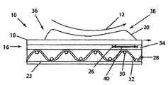
図1は、抄紙機上で紙製品に処理される繊維ウェブを脱水する長ニッププレスの側方断面図を示す。プレスニップ10は、平滑な円筒形プレスロール12と、弓形圧力シュー14とにより規定される。弓形圧力シュー14は、円筒形プレスロール12の曲率半径と同様の半径を有する。円筒形プレスロール12と弓形圧力シュー14との距離は、プレスニップ10の荷重を制御するように、弓形圧力シュー14に制御的に結合された水力手段又はこれに類する手段で調節され得る。平滑な円筒形プレスロール12は、機械を横切る方向のニップ圧力特性のレベルを得るように、弓形圧力シュー14に適合された制御型のクラウンロール(controlled crown roll)であってもよい。
FIG. 1 shows a cross-sectional side view of a long nip press that dewaters a fibrous web that is processed into a paper product on a paper machine. The press nip 10 is defined by a smooth
長ニッププレスベルト16は、弓形圧力シュー14から円筒形プレスロール12を分離するプレスニップ10を介して閉鎖ループ状に延びる。プレス布18と、紙シートに処理される繊維ウェブ20とは、図1の矢印で示す方向にプレスニップ10を介して共に通過する。繊維ウェブ20は、プレス布18で支持され、プレスニップ10において、平滑な円筒形プレスロール12と接触する。また、繊維ウェブ20は、2つのプレス布18(二番目のプレス布は示していない)で挟まれたプレスニップ10を通過してもよい。長ニッププレスベルト16は、上記の矢印で示す方向、つまり図1で示す時計回りの方向にプレスニップ10を介して移動するが、長ニッププレスベルト16は、プレス布18が弓形圧力シュー14に対して直接摺動することから防御する。また、長ニッププレスベルト16は、油の潤滑フィルム上で、弓形圧力シューに対して摺動してもよい。従って、長ニッププレスベルト16は、プレス布18及び繊維ウェブ20が汚染されないように、油に対して不透過性を有してもよい。
The long
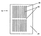
図2は、本発明の実施例に従った長ニッププレスベルト16の上面図である。長ニッププレスベルト16は、外部表面24を有する。外部表面24には、長ニッププレスベルト16の周囲で機械方向に延びる複数の溝26が設けられており、これは、プレスニップ10において、繊維ウェブ20からプレスされた水を一時的に保管するためのものである。溝26については、下記で詳細に説明する。
FIG. 2 is a top view of the long
図3乃至5は、3つの様相で、シュー型のプレスニップ10において脱水する機構を示すものであって、この様相では、溝26のひとつが、プレスニップ10に侵入し、且つ脱出する。図3は、溝26がプレスニップ10に侵入することを示す溝26の断面図である。図3から図5で連続して示すように、溝26は、ニップ入口36でプレスニップ10に侵入し、ニップ出口38でプレスニップを脱出する。
3 to 5 show a mechanism for dewatering in the shoe-type press nip 10 in three aspects. In this aspect, one of the
また、図3は、長ニッププレスベルト16の断面を示す。長ニッププレスベルト16は、少なくともひとつの基礎層28を有してもよい。しかしながら、長ニッププレスベルト16は、ポリマー樹脂コーティング34を添加した追加層を有してもよい。
FIG. 3 shows a cross section of the long
基礎層28は、横方向又は機械を横切る方向のヤーン30(図3において、側方から見たもの)と、長手方向又は機械方向のヤーン32とで織成されてもよい。基礎層28は、長手方向のヤーン32の上方、下方又はその間で織成される縦糸である横方向のヤーン30、横糸ヤーンが単一製織で、織成されてもよい。しかしながら、理解されるべきは、基礎層28は、平織りであってもよく、また、継目を有するエンドレスの形態に結合されてもよい。さらに理解されるべきは、基礎層28は、二重製織(duplex weave)で織成されてもよく、抄紙機用布製ベルトの製造に使用され得るその他の製織形態であってもよい。
The
基礎層28は、横方向及び長手方向のヤーンとを組み合わせた形態の不織構造であってもよく、これらは、布を形成するように、共通の交差点で互いに結合されてもよい。さらに、基礎層28は、ニット(knitted)又は編み上げ布(braided fabric)であってもよく、或いはGauthierによる特許文献4に記載のスパイラルリンク型のベルトであってもよい。なお、この文献を参照して、本願に取り込む。基礎層28は、ポリマー樹脂材料から、シート又は膜の形態に成形されてもよく、これらに、アパーチャを設けてもよい。さらに、少なくともひとつの基礎層28は、Johnsonによる特許文献5に開示の不織メッシュ布を有してもよい。なお、この文献を参照して、本願に取り込む。
さらに、基礎層28は、Rexfeltらによる特許文献6に開示の方法に従って、織物材料、不織材料、ニット材料、編み上げ材料、成形メッシュ材料又は不織メッシュ材料のストリップを螺旋巻きにして、作製されてもよい。なお、この文献を参照して、本願に取り込む。基礎層28は、螺旋巻きのストリップを有してもよく、これらの各巻きは、長手方向にエンドレスの形態で基礎構造28を形成する連続継目で隣に接合(join)される。この種の基礎構造を有するプレスベルトは、特許文献7及び8に開示されている。なお、これらの文献を参照して、本願に取り込む。
Further, the
ポリマー樹脂などの樹脂34は、長ニッププレスベルト16の少なくともひとつの表面上にコーティング、含浸又はその他の配置方法で配置される。ポリマー樹脂34は、長ニッププレスベルト16の外部表面24上にコーティング又はその他の手段で配置され得る。つまり、この表面は、長ニッププレスベルト16が長ニッププレスにおいて使用される場合、プレス布18と接する。加えて、ポリマー樹脂層23は、長ニッププレスベルト16の内部表面22上にコーティング又はその他の手段で配置され得る。つまり、その表面は、長ニッププレスベルト16が長ニッププレスにおいて使用される場合、弓形圧力シュー14上を摺動する。ポリマー樹脂層23は、基礎層28を含浸してもよく、また、油、水及びこれらに類する材料に不透過な長ニッププレスベルト16を提供してもよい。ポリマー樹脂コーティング34及び23は、ポリウレタン製であってもよく、また、これらの固形成分が100%であってもよい。本質的に溶媒材料を含まない100%の固形樹脂系を使用すると、基礎層28上に以下の適用例に従って処理する硬化工程中、ポリマー樹脂中に泡の形成が阻止される。
A
内部表面22及び/又は外部表面24は、平滑で、均一な表面を有するポリマー樹脂コーティングを提供するようにポリマー樹脂が硬化された後、接地されてもよく、またバフ仕上げされてもよい。
ポリマー樹脂が硬化された後、溝26は、長ニッププレスベルト16の外部表面24に切断されてもよい。また、溝26は、ポリマー樹脂が硬化される前にプレス型の装置で外部表面24にプレスされてもよく、或いは(長ニッププレスベルト16が成形工程で製造される場合など)外部表面24に成形されてもよい。理解されるように、溝26を形成するその他の可能性のある方法については、当業者に明らかである。
After the polymer resin is cured, the
さらに、本発明の少なくともひとつの実施例において、溝26は、連続ではない。つまり、溝26は、隣り合う(また、連続した)溝間で溝を付されていない領域である島領域42で分離される。溝26は、ベルトの機械方向又は機械を横切る方向のいずれの方向で形成されてもよい。図3乃至5に示すような、機械方向に形成された溝を有するひとつの好適実施例において、溝26は、ベルトの機械方向に形成され、例えば(図1の)弓形圧力シュー14の長さより小さい値を有する長さなどの長さ40を有する。なお、この値は、弓形圧力シューの長さの約1/3、1/2、2/3などが例示される。例として、典型的な弓形圧力シューの長さが約250mmである場合、溝26の長さ40は、約125mmであってもよい。同様に、図11においては、溝26が機械を横切る方向に形成された実施例を示す。
Further, in at least one embodiment of the present invention, the
溝26の形状、寸法、間隔及び配列は、適用する長ニッププレス並びに/又は所望する侵入するニップスプレーの開放度及び脱水工程の効率に従って、種々変更されてもよい。
The shape, size, spacing and arrangement of the
上述及び図3に示すように、溝26は、ニップ入口36でプレスニップ10に侵入し、ニップ出口38でプレスニップ10を脱出する。ニップ入口36は、低い圧力領域としての特徴を有する。繊維ウェブ20がプレスニップ10に侵入するので、円筒形プレスロール12及び弓形圧力シュー14から適用される圧力は、繊維ウェブ20に含まれる水を、長ニッププレスベルト16と接触するプレス布18に流動させる。溝26は、その後、プレス布18からの水を受容する。
As described above and shown in FIG. 3, the
図4は、溝26がプレスニップ10に包含された長ニッププレスベルト16の断面図を示す。溝26は、ここでは、繊維ウェブ20及びプレス布18からの水が圧力状態にある水圧領域(hydrostatic zone)に侵入する。は、そのボイド容量が完全に充填されるまで、水を受容する。
FIG. 4 shows a cross-sectional view of the long
図5は、溝26がプレスニップ10を脱出した長ニッププレスベルト16の断面図を示す。ニップ出口38は、高い圧力領域としての特徴を有する。ニップ出口38近傍では、最も高い圧力状態となり、従って、最も高い水除去性を有する。溝26が連続しておらず、弓形圧力シュー14の長さよりも短いので、溝は、ニップ入口にまで及んでおらず、言い換えれば、ニップ入口36は、閉鎖されている。また、繊維ウェブ20から除去されプレス布18から長ニッププレスベルト16へと及ぼされる水は、図4について述べた流体圧力を構築する。この流体圧力の構築は、ニップ出口38でプレスニップ10を脱出する際、水を溝26から脱出させる。従って、高い圧力は、繊維ウェブ20及びプレス布18から今や曝露された溝26への水流を駆動する。
FIG. 5 shows a cross-sectional view of the long
図2、6、7、7a及び7bは、種々の溝の配置を示す。図2に示すように、溝26は、同数の列に配列されてもよく、ひとつの列における各溝の端部を交差する線は、長手方向に実質的に垂直である。しかしながら、ひとつの列における溝の数と、長ニッププレスベルト16上の長手方向において隣り合う列間の距離とは、適用する長ニッププレスに従って、種々変更されてもよく、及び/又は所望する侵入するニップスプレーの開放度及び/又は脱水工程の効率に従って、種々変更されてもよい。上述したように、溝26は、長手方向に連続していなくてもよく、また、弓形圧力シュー14の長さよりも短くてもよい。溝26は、図2に示すように、島領域42で互いに分離される。
Figures 2, 6, 7, 7a and 7b show various groove arrangements. As shown in FIG. 2, the
図6は、本発明の他の実施例に従ったベルト16’の上面図である。この例において、MD方向の溝26は、均一なオフセットを有する互い違いの行(staggered row)に形成される。このオフセットは、角度αとして示す。角度αは、例えば、25〜30°であってもよい。
FIG. 6 is a top view of a
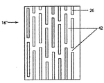
図7は、本発明の他の実施例に従ったベルト16’’の上面図である。ここで、MD方向の溝26は、繰り返しでない横方向のパターンで互い違いの列に形成される。他の実施例としては、互い違いの列の繰り返しパターンが挙げられる。
FIG. 7 is a top view of a
図7aは、機械方向におけるさらに別の溝のパターンを示しており、複数の溝が、反復可能なクラスター又はパターン100で形成されている。図7aに示すように、連続した溝26のクラスター100は、例えば機械方向に一定の角度で実質的に延びる10の溝を有する。斯かる溝は、螺旋様式で典型的に切断される「ギャングカッター(gang cutters)」として公知の手段で、切断されてもよい。ベルトは、ベルトの適当な脱水特性に所望されるように、複数の溝クラスター100を有する。クラスターは、機械方向に一定の角度を有するように示されているが、他の配列も本発明の範囲に含まれ、例えば、機械を横切る方向が例示される。さらに、クラスター100は、同様の配列で示されているが、本発明は、この態様に限定されるものではなく、むしろ、同じベルト上に、種々の配列でクラスターが形成されてもよい。図7bは、ベルトに形成された重なりあう溝26を有する本発明のさらに別の実施例を示す。この重なりあう溝26は、反復パターンでベルトの全体を包囲する不連続な溝をもたらす。再び記するが、図7bに示す溝26は、機械方向に一定の角度を有するように示されているが、機械を横切る方向を含む種々の配列で形成されてもよい。ベルトの長さに沿って種々の距離で複数の溝を有することにより、溝を有さないベルトの一部で発生するマーキング(marking)の発生は、軽減される。
FIG. 7 a shows yet another groove pattern in the machine direction, where a plurality of grooves are formed with repeatable clusters or
本発明の実施例において、機械方向における溝26の長さは、シューの長さを略上限として、種々の長さであってもよい。例えば、溝26は、約50mmの長さを有してもよく、また、長手方向における溝26間の距離は、約25mmであってもよい。さらに、溝26及び島領域42は、水圧の崩壊及び紙シートのマーキングを最小限にする種々のパターンで配列されてもよい。溝26及び島領域42は、図2、6及び7では等幅で示されているが、これに限るものではない。それにもかかわらず、島領域42は、ベルトの外部表面24上に、機械方向で配列された硬化ポリマー樹脂の狭い幅のピラー(pillar)として考慮されてもよい。
In the embodiment of the present invention, the length of the
MD方向の溝26は、機械方向又は長手方向に配列されているものとして述べてきた。溝26は、外部表面24上で螺旋巻きとなる不連続な溝を切断して、設けられてもよい。斯かる状況において、溝26の配列は、小さい角度で、機械方向又は長手方向から離れてもよい。加えて、溝26は、外部表面24上で螺旋巻きとなる、つまり、ひとつは右の螺旋巻きであり、もうひとつが左の螺旋巻きであるように、2つ以上の隣り合う不連続な溝を対向する方向で切断して、設けられてもよい。カッターは、機械を横切る方向における島領域の短い水平方向のストリップ(CDストリップ)を形成するベルト表面から間欠的に除去されてもよい。このCDストリップは、ベルトの長さ、溝の長さ、島領域の長さに依存してベルトの表面に対してランダム化されてもよい。
The
本発明の有利な実施例において、溝26は、約1.4mmの深さと、0.5〜2.0mmの幅とを有してもよい。各溝26は、横方向で、1.0〜2.5mmの距離で隣の溝と分離されていてもよい。しかしながら、溝26の正確な数、深さ、幅及び形状とともに、島領域42の幅は、所望する適用例に依存して、種々変更されてもよい。従って、島領域に対する溝の割合は、広範なものとなる。
In an advantageous embodiment of the invention, the
溝は、長手方向又は機械方向に延びるものとして述べてきたが、本発明は、これに限定されるものではない。つまり、溝は、例えば、横方向又は機械を横切る方向(CD)、又は機械方向に相対して角度θ(0<θ<90°)の方向など、種々の方向に配列されてもよい。斯かる状況において、溝26の長さは、例えば、図11及び12に示すように、シューの幅よりも短くてもよい。
Although the grooves have been described as extending in the longitudinal direction or the machine direction, the present invention is not limited thereto. That is, the grooves may be arranged in various directions, for example, in the lateral direction or in the direction across the machine (CD), or in the direction of angle θ (0 <θ <90 °) relative to the machine direction. In such a situation, the length of the
図11に示すように、溝26は、複数の列状に配列されてもよく、各溝は、横方向又はCD方向に実質的に形成される。しかしながら、ベルト上の、列における溝の数及びCD方向又は横方向における隣り合う列間の距離は、適用例並びに/又は所望する侵入するニップスプレーの開放度及び脱水工程の効率に従って、種々変更されてもよい。斯かる溝26は、横方向の長さに沿って不連続なものと考慮されてもよく、また弓形圧力シュー14の長さよりも短い幅(MD成分)を有してもよい。また、CD方向の溝は、図11aに示すように、連続していてもよく、ここで、溝26は、ベルト17の機械を横切る方向の幅の実質的に全体で延びている。さらに別の代替実施例において、溝26は、図12に示すベルト17’のように、互い違いのパターンで形成されてもよい。
As shown in FIG. 11, the
CD方向又は横方向の溝を有するシュー型のニッププレスベルトは、容積移送式ポンプ用の羽根車又はギアと類似の有利な作用効果を有する。溝26がシューに侵入すると、水は、繊維ウェブ20から脱出し、ベルト17の溝26へと至る。溝26が樹脂34で形成されているので、水が透過せず、水は、溝26を流れ出ない。円筒形プレスロール12とシューとの圧力が増加すると、溝26は、繊維ウェブ20からの水で充填される。ベルト17の動きにより、その後、繊維ウェブ20から水が出て溝26へと運搬される。
A shoe-type nip press belt having grooves in the CD direction or the transverse direction has advantageous effects similar to those of an impeller or gear for a positive displacement pump. When the
溝26の幅(MD成分)がシューの長さよりも小さいので、溝に侵入する水は、流出せず、円筒形プレスロール12に適用される高圧に一部起因して、溝内に留められる。斯かる実施例は、従来の平坦ベルト又は溝を有さないベルトで使用される低速の適用例で非常に有用であることを証明し得る。しかしながら、本発明は、この態様に限定されるものではなく、事実、種々の速度で使用され得る。
Since the width of the groove 26 (MD component) is smaller than the length of the shoe, the water that enters the groove does not flow out and is retained in the groove due in part to the high pressure applied to the
また、本発明によるベルトは、その他のパターンの不連続な溝を有してもよい。例として、図13を参照すると、本発明によるベルトは、複数の第一溝(例えば溝44)及び/又は複数の第二溝(例えば溝46)を有してもよい。斯かる溝のそれぞれは、弓形圧力シュー14の長さよりも短い全長及び全幅を有してもよい。 The belt according to the present invention may have other patterns of discontinuous grooves. As an example, referring to FIG. 13, a belt according to the present invention may have a plurality of first grooves (eg, grooves 44) and / or a plurality of second grooves (eg, grooves 46). Each such groove may have an overall length and width that is less than the length of the arcuate pressure shoe 14.
長ニッププレスベルト16(図2)を、標準的な型の連続した溝を有するベルトと比較する場合、ベルトの溝が1.4mmの深さと0.8mmの幅とを有する場合、及び島領域の幅(隣り合う溝間の距離)が2.1mmである場合、侵入するニップスプレー及び脱出するニップスプレーは、機械の速度及び印加されるニップ圧力に対して、測定され、プロットされ得る。 When comparing the long nip press belt 16 (FIG. 2) with a belt with a standard type of continuous groove, the belt groove has a depth of 1.4 mm and a width of 0.8 mm, and the island region If the width (distance between adjacent grooves) is 2.1 mm, ingress and exit nip sprays can be measured and plotted against machine speed and applied nip pressure.
図8に示すように、標準的な連続する溝を有するベルトについて、300m/分の機械速度で侵入するニップスプレーが発生する。また、図示するように、機械速度が増加するにつれ、侵入するニップスプレーも増大し、その後、減少した。また、荷重する圧力が増加するにつれ、侵入するニップスプレーは、増加した。従って、標準的な溝を有するシュー型のプレスベルトを動作するには、好ましくない動作範囲が存在する。 As shown in FIG. 8, a nip spray that enters at a machine speed of 300 m / min occurs for a belt with a standard continuous groove. Also, as shown, as the machine speed increased, the invading nip spray increased and then decreased. Also, as the loading pressure increased, the nip spray that penetrated increased. Therefore, there is an unfavorable operating range for operating a shoe-type press belt having a standard groove.
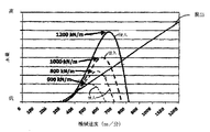
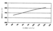
図9は、ベルトがシュー型のニッププレスに侵入するにつれ侵入するニップスプレーが実質的に消失する動作速度を示す。このグラフは、連続した溝を有するシュー型のプレスベルトにおいて、プレス荷重を種々変化させた際の機械速度を示す。明らかなように、プレス荷重が増加すると、侵入するニップスプレーを消失させるのに必要な機械速度は、増加した。例えば、600kN/mのプレス荷重において、侵入するニッププレスを消失させるのに必要な機械速度は、約650m/分であって、1200kN/mのプレス荷重では、侵入するニップスプレーを消失させるのに必要な機械速度は、約810m/分である。 FIG. 9 shows the operating speed at which the invading nip spray substantially disappears as the belt enters the shoe-type nip press. This graph shows the machine speed when the press load is variously changed in a shoe-type press belt having continuous grooves. As is apparent, as the press load increased, the machine speed required to eliminate the invading nip spray increased. For example, at a press load of 600 kN / m, the machine speed required to eliminate the intruding nip press is about 650 m / min, and at a press load of 1200 kN / m, the intruding nip spray disappears. The required machine speed is about 810 m / min.
図8及び9に示すように、侵入するニップスプレーは、プレス荷重の範囲を600kN/m〜1200kN/m以下で動作させる際、約650m/分以上810m/分未満の速度で進行する、標準型の連続するMD方向の溝を有するベルトを用いたシュー型の長プレスで存在し得る。この侵入するニップスプレーは、ウェブの脱水効果を低減し、従って、公知の溝を有するベルトの所望しない特性である。 As shown in FIGS. 8 and 9, the invading nip spray advances at a speed of about 650 m / min or more and less than 810 m / min when operating at a press load range of 600 kN / m to 1200 kN / m or less. Can be present in a shoe-type long press using a belt having a continuous MD groove. This intruding nip spray reduces the dewatering effect of the web and is therefore an undesired property of belts with known grooves.
逆に、図10で示すように、本発明によるベルトは、250m/分〜1000m/分の速度で、600kN/m〜1000kN/mのプレス荷重で、侵入するニップスプレーが消失、又は実質的に消失する。従って、不連続な溝を有するベルトは、侵入するニップスプレーを減少させ、従って、ウェブの脱水効率を増加させ得る。 On the contrary, as shown in FIG. 10, the belt according to the present invention loses, or substantially disappears, the intruding nip spray with a press load of 600 kN / m to 1000 kN / m at a speed of 250 m / min to 1000 m / min. Disappear. Thus, belts with discontinuous grooves can reduce ingress nip spray and thus increase web dewatering efficiency.
本発明によるベルトについて、不連続な溝を有するように説明してきたが、本発明は、これに限定されるものではない。つまり、本発明のベルトは、標準的でない連続した溝を有してもよい。例としては、図14に示すように、ベルト47は、複数の連続した溝49を有してもよく、この溝のそれぞれは、直線部分48と、その後に、ジグザグ部分50を有し、さらにその後に、別の直線部分48などを有する。直線部分及び/又はジグザグ部分における溝の長さは、弓形圧力シュー14の長さよりも短くてもよい。他の例としては、図15を参照すると、ベルト51は、一つ以上の溝52を有してもよく、そのそれぞれは、第一幅を有する複数の第一部分54と、第一幅よりも狭い第二幅を有する複数の第二部分56とを有する。第二部分又は限定部分56の長さは、弓形圧力シュー14の長さよりも短くてもよい。
Although the belt according to the present invention has been described as having discontinuous grooves, the present invention is not limited to this. That is, the belt of the present invention may have non-standard continuous grooves. As an example, as shown in FIG. 14, the
さらに、上述したように、本発明によるベルトに利用される溝の形状は、複数の異なる断面形状を有してもよい。斯かる断面形状の例を図16乃至21に示す。理解されるように、本発明によるベルトの溝の形状は、これらの形状に限定されるものではない。 Furthermore, as described above, the shape of the groove utilized in the belt according to the present invention may have a plurality of different cross-sectional shapes. Examples of such cross-sectional shapes are shown in FIGS. As will be appreciated, the shape of the groove of the belt according to the present invention is not limited to these shapes.
本発明のさらに利点を有する実施例を、図22に示す。図22において、溝26は、より深い溝部分60と、より浅い溝部分62とを有する種々の深さに形成されてもよい。深さの変化は、上述の不連続な溝において溝の端部として実質的に機能する。つまり、溝26のより浅い溝部分62は、より深い溝部分60へと容易に水が流出することを阻止し、これにより、機械方向に対向する方向へと水が流動する傾向が優位に減少し、ニップスプレーが最小限となる。
An embodiment having further advantages of the present invention is shown in FIG. In FIG. 22, the
本発明による実施例における溝26は、しかしながら、一つの有利な実施例において、溝26のより深い溝部分60は、シューのプレス領域の長さよりも短い長さを有する。図22に示した圧力曲線64との比較で、溝26の深さにて、見出され得る。円筒形プレスロール12の入口には、溝26のより浅い溝部分62に対応する低い圧力領域36が存在する。その後、この圧力は、急速に上昇し、溝26の深さは、この領域において、増加する。最も高い圧力は、溝26のより深い溝部分60の端部の若干手前の位置で発生する。
The
より浅い溝部分62の領域において、圧力は、劇的に低下する。従って、溝26の最も深い部分では、最も高い圧力が記録され、最も多量の水が、繊維ウェブ20から除去される。明瞭に示すため、図22では、繊維ウェブ20が運搬される(図1の符番18で示す)プレス布は示さないが、当業者は、斯かる布を繊維ウェブ20と長ニッププレスベルト16との間に典型的に配置することを理解するであろう。
In the region of the
上述の事項に対する改変は、当業者に明らかであるが、斯かる改変は、添付した特許請求の範囲を超えて本発明を改変するものではない。 Modifications to the above will be apparent to those skilled in the art, but such modifications do not alter the invention beyond the scope of the appended claims.
10 プレスニップ
12 円筒形プレスロール
14 弓形圧力シュー
16 長ニッププレスベルト
16’ ベルト
16’’ ベルト
17 ベルト
17’ ベルト
18 プレス布
20 繊維ウェブ
22 内部表面
23 ポリマー樹脂層
24 外部表面
26 溝
28 基礎層
30 ヤーン
32 ヤーン
34 樹脂
36 ニップ入口
38 ニップ出口
40 長さ
42 島領域
44 溝
46 溝
47 ベルト
48 直線部分
49 溝
50 ジグザグ部分
51 ベルト
52 溝
54 第一部分
56 第二部分
60 より深い溝部分
62 より浅い溝部分
64 圧力曲線
α 角度
DESCRIPTION OF
Claims (52)
内部表面及び外部表面を有する基礎布と;
該基礎布の該外部表面上に形成され該基礎布と実質的に共通の広がりを有する樹脂コーティング層と;
該樹脂コーティング層に形成された不連続な複数の溝であって、該溝の少なくともひとつは、第二部分の幅よりも大きな幅を有する第一部分を有する、複数の溝と;
を有することを特徴とするベルト。A belt that minimizes intrusion of nip spray in shoe presses:
A base fabric having an inner surface and an outer surface;
A resin coating layer formed on the outer surface of the base fabric and having a spread substantially in common with the base fabric;
A plurality of discontinuous grooves formed in the resin coating layer, wherein at least one of the grooves has a first portion having a width greater than a width of the second portion;
A belt characterized by comprising:
内部表面及び外部表面を有する基礎布と;
該基礎布の該外部表面上に形成され該基礎布と実質的に共通の広がりを有する樹脂コーティング層と;
該コーティング層に形成された不連続な複数の溝であって、該溝は、互いに平行であり、且つ機械方向に互いに一定でない距離でオフセットである、複数の溝と;
を有することを特徴とするベルト。A belt that minimizes intrusion of nip spray in shoe presses:
A base fabric having an inner surface and an outer surface;
A resin coating layer formed on the outer surface of the base fabric and having a spread substantially in common with the base fabric;
A plurality of discontinuous grooves formed in the coating layer, the grooves being parallel to each other and offset by a non-constant distance from each other in the machine direction;
A belt characterized by comprising:
内部表面及び外部表面を有する基礎布と;
該基礎布の外部表面上に形成され該基礎布と実質的に共通の広がりを有する樹脂コーティング層と;
該コーティング層に形成された不連続な複数の溝であって、該溝は、互いに平行であり、且つ反復でないパターンで互いに交互に配置されている、複数の溝と;
を有することを特徴とするベルト。A belt that minimizes intrusion of nip spray in shoe presses:
A base fabric having an inner surface and an outer surface;
A resin coating layer formed on the outer surface of the base fabric and having a spread substantially common to the base fabric;
A plurality of discontinuous grooves formed in the coating layer, wherein the grooves are parallel to each other and alternately disposed in a non-repeating pattern;
A belt characterized by comprising:
内部表面及び外部表面を有する基礎布と;
該基礎布の該外部表面上に形成され該基礎布と実質的に共通の広がりを有する樹脂コーティング層と;
該樹脂コーティング層に形成された複数の溝と;
を有し、
前記溝は、異なる形状の組み合わせ、異なる深さの組み合わせ、及び異なる角度の配向の組み合わせの中の1以上の組み合わせによって形成されており、
前記溝の少なくとも一つは、侵入するニップスプレーを低減するように、第二部分の幅よりも大きな幅を有する第一部分を有することを特徴とするベルト。A belt that minimizes intrusion of nip spray in shoe presses:
A base fabric having an inner surface and an outer surface;
A resin coating layer formed on the outer surface of the base fabric and having a spread substantially in common with the base fabric;
A plurality of grooves formed in the resin coating layer;
Have
The groove combination of different shapes are formed by one or more combinations of the combinations of the orientation of a combination of different depths, and different angles,
At least one of the grooves has a first portion having a width greater than the width of the second portion so as to reduce ingress nip spray.
内部表面及び外部表面を有する基礎布と;
該基礎布の該外部表面上に形成され該基礎布と実質的に共通の広がりを有する樹脂コーティング層と;
該樹脂コーティング層に形成された複数の溝と;
を有し、
前記溝は、異なる形状の組み合わせ、異なる深さの組み合わせ、異なる幅の組み合わせ、及び異なる
角度の配向の組み合わせの中の1以上の組み合わせによって形成されており、
前記溝は、直線の第一部分と正弦又はジグザグの第二部分とを含み、前記第一部分及び前記第二部分は、機械方向に実質的に延びていることを特徴とするベルト。A belt that minimizes intrusion of nip spray in shoe presses:
A base fabric having an inner surface and an outer surface;
A resin coating layer formed on the outer surface of the base fabric and having a spread substantially in common with the base fabric;
A plurality of grooves formed in the resin coating layer;
Have
The groove combination of different shapes, combinations of different depths are formed by different combinations of widths, and different <br/> angles least one combination of the combinations of orientation,
The belt includes a straight first portion and a sine or zigzag second portion, the first portion and the second portion extending substantially in the machine direction.
内部表面を及び外部表面を有するプレスベルトに基礎布を設けるステップと;
前記基礎布の外部表面上にポリマー樹脂を堆積するステップと;
前記ポリマー樹脂に不連続な複数の溝を形成するステップと;
を有し、
前記溝は、異なる形状の組み合わせ、異なる深さの組み合わせ、及び異なる角度の配向の組み合わせの中の1以上の組み合わせによって形成されており、
前記溝の少なくとも一つは、第二部分の幅よりも大きな幅を有する第一部分を有することを特徴とする方法。A method of manufacturing a belt that minimizes nip spray penetrating in a shoe press, comprising:
Providing a base fabric on a press belt having an inner surface and an outer surface;
Depositing a polymer resin on the outer surface of the base fabric;
Forming a plurality of discontinuous grooves in the polymer resin;
Have
The groove combination of different shapes are formed by one or more combinations of the combinations of the orientation of a combination of different depths, and different angles,
At least one of the grooves has a first portion having a width greater than the width of the second portion.
内部表面及び外部表面を有するプレスベルトに基礎布を設けるステップと;
前記基礎布の外部表面上にポリマー樹脂を堆積するステップと;
前記ポリマー樹脂に不連続な複数の溝を形成するステップと;
を有し、
前記溝は、異なる形状の組み合わせ、異なる深さの組み合わせ、異なる幅の組み合わせ、及び異なる角度の配向の組み合わせの中の1以上の組み合わせによって形成されており、
前記溝は、直線の第一部分と正弦又はジグザグの第二部分とを含み、前記第一部分及び前記第二部分は、機械方向に実質的に延びていることを特徴とする方法。A method of manufacturing a belt that minimizes nip spray penetrating in a shoe press, comprising:
Providing a base fabric on a press belt having an inner surface and an outer surface;
Depositing a polymer resin on the outer surface of the base fabric;
Forming a plurality of discontinuous grooves in the polymer resin;
Have
The groove combination of different shapes, combinations of different depths are formed by different combinations of widths, and different angles of one or more combinations of the combinations of orientation,
The groove includes a straight first portion and a sine or zigzag second portion, the first portion and the second portion extending substantially in the machine direction.
内部表面及び外部表面を有する基礎布と;
該基礎布の該外部表面上に形成され該基礎布と実質的に共通の広がりを有する樹脂コーティング層と;
該樹脂コーティング層に形成された機械を横切る方向に連続な複数の溝と;
を有し、
前記溝は、異なる形状の組み合わせ、異なる深さの組み合わせ、異なる幅の組み合わせ、及び異なる角度の配向の組み合わせの中の2以上の組み合わせによって形成されていることを特徴とするベルト。A belt that minimizes intrusion of nip spray in shoe presses:
A base fabric having an inner surface and an outer surface;
A resin coating layer formed on the outer surface of the base fabric and having a spread substantially in common with the base fabric;
A plurality of grooves continuous in a direction across the machine formed in the resin coating layer;
Have
The groove different combinations of shapes, a combination of different depths, the combination of different widths, and different angles 2 or more sets saw belt, characterized in that it is formed by the case so I in combination of orientation.
内部表面及び外部表面を有する基礎布と;
該基礎布の該外部表面上に形成され該基礎布と実質的に共通の広がりを有する樹脂コーティング層と;
該樹脂コーティング層に形成された機械を横切る方向に連続な複数の溝と;
を有し、
前記樹脂コーティング層に形成された機械方向に不連続な複数の溝をも有することを特徴とするベルト。A belt that minimizes intrusion of nip spray in shoe presses:
A base fabric having an inner surface and an outer surface;
A resin coating layer formed on the outer surface of the base fabric and having a spread substantially in common with the base fabric;
A plurality of grooves continuous in a direction across the machine formed in the resin coating layer;
Have
A belt having a plurality of grooves discontinuous in the machine direction formed in the resin coating layer.
内部表面及び外部表面を有するプレスベルトに基礎布を設けるステップと;
前記基礎布の該外部表面上にポリマー樹脂を堆積するステップと;
前記ポリマー樹脂に複数の溝を形成するステップと;
を有し、
前記溝の少なくとも一つは、第二部分の幅よりも大きな幅を有する第一部分を有することを特徴とする方法。A method of manufacturing a belt that minimizes nip spray penetrating in a shoe press, comprising:
Providing a base fabric on a press belt having an inner surface and an outer surface;
Depositing a polymer resin on the outer surface of the base fabric;
Forming a plurality of grooves in the polymer resin;
Have
At least one of the grooves has a first portion having a width greater than the width of the second portion.
内部表面及び外部表面を有する基礎布と;
該基礎布の該外部表面上に形成され該基礎布と実質的に共通の広がりを有する樹脂コーティング層と;
該樹脂コーティング層に形成された不連続な複数の溝と;
を有し、
前記溝は、直線の第一部分と正弦又はジグザグの第二部分とを含み、前記第一部分及び前記第二部分は、機械方向に実質的に延びていることを特徴とするベルト。A belt that minimizes intrusion of nip spray in shoe presses:
A base fabric having an inner surface and an outer surface;
A resin coating layer formed on the outer surface of the base fabric and having a spread substantially in common with the base fabric;
A plurality of discontinuous grooves formed in the resin coating layer;
Have
The belt includes a straight first portion and a sine or zigzag second portion, the first portion and the second portion extending substantially in the machine direction.
内部表面及び外部表面を有する基礎布と;
該基礎布の該外部表面上に形成され該基礎布と実質的に共通の広がりを有する樹脂コーティング層と;
該樹脂コーティング層に形成された機械を横切る方向に不連続な複数の溝であって、作動中開口状態である、複数の溝と;
を有することを特徴とするベルト。A belt that minimizes intrusion of nip spray in shoe presses:
A base fabric having an inner surface and an outer surface;
A resin coating layer formed on the outer surface of the base fabric and having a spread substantially in common with the base fabric;
A plurality of grooves discontinuous across the machine formed in the resin coating layer, the grooves being open during operation;
A belt characterized by comprising:
内部表面及び外部表面を有する基礎布と;
該基礎布の該外部表面上に形成され該基礎布と実質的に共通の広がりを有する樹脂コーティング層と;
該樹脂コーティング層に形成された機械を横切る方向に不連続な複数の溝と;
を有し、
前記樹脂コーティング層に形成された機械方向に不連続な複数の溝をも有することを特徴とするベルト。A belt that minimizes intrusion of nip spray in shoe presses:
A base fabric having an inner surface and an outer surface;
A resin coating layer formed on the outer surface of the base fabric and having a spread substantially in common with the base fabric;
A plurality of grooves discontinuous in the direction across the machine formed in the resin coating layer;
Have
A belt having a plurality of grooves discontinuous in the machine direction formed in the resin coating layer.
内部表面及び外部表面を有する基礎布と;
該基礎布の該外部表面上に形成され該基礎布と実質的に共通の広がりを有する樹脂コーティング層と;
該樹脂コーティング層に形成された不連続な複数の溝と;
を有し、
前記溝は、実質的に機械方向に形成されており、前記溝は、長さに沿って種々の幅と種々の深さとを有することを特徴とするベルト。A belt that minimizes intrusion of nip spray in shoe presses:
A base fabric having an inner surface and an outer surface;
A resin coating layer formed on the outer surface of the base fabric and having a spread substantially in common with the base fabric;
A plurality of discontinuous grooves formed in the resin coating layer;
Have
The belt is characterized in that the groove is formed substantially in the machine direction, and the groove has various widths and various depths along its length.
内部表面及び外部表面を有する基礎布と;
該基礎布の該外部表面上に形成され該基礎布と実質的に共通の広がりを有する樹脂コーティング層と;
該樹脂コーティング層に形成された不連続な複数の溝と;
を有し、
前記溝は、実質的に機械を横切る方向に形成されており、前記溝は、長さに沿って種々の幅と種々の深さとを有することを特徴とするベルト。A belt that minimizes intrusion of nip spray in shoe presses:
A base fabric having an inner surface and an outer surface;
A resin coating layer formed on the outer surface of the base fabric and having a spread substantially in common with the base fabric;
A plurality of discontinuous grooves formed in the resin coating layer;
Have
The belt is formed in a direction substantially across the machine, the groove having various widths and various depths along the length.
内部表面及び外部表面を有する基礎布と;
該基礎布の該外部表面上に形成され該基礎布と実質的に共通の広がりを有する樹脂コーティング層と;
該樹脂コーティング層に形成された不連続な複数の溝と;
を有し、
前記溝は、実質的に機械を横切る方向に形成されており、
前記溝の機械方向の長さは、シュープレスの機械方向の長さよりも小さく、
前記溝の少なくとも一つは、長さに沿って種々の深さを有することを特徴とするベルト。A belt that minimizes intrusion of nip spray in shoe presses:
A base fabric having an inner surface and an outer surface;
A resin coating layer formed on the outer surface of the base fabric and having a spread substantially in common with the base fabric;
A plurality of discontinuous grooves formed in the resin coating layer;
Have
The groove is formed in a direction substantially across the machine;
The length of the groove in the machine direction is smaller than the length of the shoe press in the machine direction,
At least one of the grooves has various depths along its length.
Applications Claiming Priority (3)
| Application Number | Priority Date | Filing Date | Title |
|---|---|---|---|
| US52313503P | 2003-11-18 | 2003-11-18 | |
| US60/523,135 | 2003-11-18 | ||
| PCT/US2004/038045 WO2005049917A1 (en) | 2003-11-18 | 2004-11-15 | Shoe press belt having a grooved surface |
Publications (3)
| Publication Number | Publication Date |
|---|---|
| JP2007511681A JP2007511681A (en) | 2007-05-10 |
| JP2007511681A5 JP2007511681A5 (en) | 2010-01-07 |
| JP4846593B2 true JP4846593B2 (en) | 2011-12-28 |
Family
ID=34619574
Family Applications (1)
| Application Number | Title | Priority Date | Filing Date |
|---|---|---|---|
| JP2006541288A Active JP4846593B2 (en) | 2003-11-18 | 2004-11-15 | Shoe-type pressure belt having a groove surface |
Country Status (15)
| Country | Link |
|---|---|
| US (1) | US7387711B2 (en) |
| EP (1) | EP1694911A1 (en) |
| JP (1) | JP4846593B2 (en) |
| KR (1) | KR101149335B1 (en) |
| CN (2) | CN1882745B (en) |
| AU (1) | AU2004291899A1 (en) |
| BR (1) | BRPI0416312B1 (en) |
| CA (1) | CA2546036C (en) |
| DE (1) | DE4810980T1 (en) |
| MX (1) | MXPA06005488A (en) |
| NO (1) | NO20062833L (en) |
| RU (1) | RU2406792C2 (en) |
| TW (1) | TW200528610A (en) |
| WO (1) | WO2005049917A1 (en) |
| ZA (1) | ZA200603974B (en) |
Families Citing this family (10)
| Publication number | Priority date | Publication date | Assignee | Title |
|---|---|---|---|---|
| US8080137B2 (en) * | 2003-11-18 | 2011-12-20 | Albany International Corp. | Shoe press belt having a grooved surface |
| JP5412028B2 (en) * | 2006-12-22 | 2014-02-12 | ヤマウチ株式会社 | Shoe press belt |
| JP4477025B2 (en) | 2007-03-12 | 2010-06-09 | イチカワ株式会社 | Shoe press belt for papermaking |
| JP4972438B2 (en) * | 2007-03-22 | 2012-07-11 | イチカワ株式会社 | Shoe press belt for papermaking |
| DE102007025816A1 (en) * | 2007-06-02 | 2008-12-04 | Voith Patent Gmbh | roll shell |
| WO2009066700A1 (en) | 2007-11-20 | 2009-05-28 | Ichikawa Co., Ltd. | Paper making shoe press belt |
| DE102011004565A1 (en) | 2011-02-23 | 2012-08-23 | Voith Patent Gmbh | Press section of a machine for producing a fibrous web |
| CN105351727B (en) * | 2015-10-26 | 2018-01-02 | 北京强幕工贸有限责任公司 | A kind of resin edge sealing sheet material |
| WO2017139786A1 (en) * | 2016-02-11 | 2017-08-17 | Structured I, Llc | Belt or fabric including polymeric layer for papermaking machine |
| FI20226166A1 (en) * | 2022-12-27 | 2024-06-28 | Valmet Technologies Oy | Belt |
Citations (3)
| Publication number | Priority date | Publication date | Assignee | Title |
|---|---|---|---|---|
| JPS5925394A (en) * | 1982-07-30 | 1984-02-09 | Suntory Ltd | (1r,5r)-4z-ethylidene-2,8-dioxabicyclo(3.3.1)nonane |
| JPS617117A (en) * | 1984-06-19 | 1986-01-13 | Yamauchi Rubber Ind Co Ltd | Endless belt |
| DE19752725A1 (en) * | 1997-11-28 | 1999-06-02 | Voith Sulzer Papiertech Patent | Pressure application mantle on roller |
Family Cites Families (26)
| Publication number | Priority date | Publication date | Assignee | Title |
|---|---|---|---|---|
| FR2494318B1 (en) * | 1980-11-14 | 1986-10-10 | Feutres Papeteries Tissus Indl | BAND CONSISTING OF SPIRALS |
| US5238537A (en) * | 1981-09-15 | 1993-08-24 | Dutt William H | Extended nip press belt having an interwoven base fabric and an impervious impregnant |
| FI75620C (en) * | 1982-04-01 | 1988-07-11 | Tampella Oy Ab | LAONGZONSPRESS FOER EN PAPPERSMASKIN. |
| US4427734A (en) * | 1982-04-19 | 1984-01-24 | Albany International Corp. | Wet press felt for papermaking machines |
| JPS5925394U (en) * | 1982-08-03 | 1984-02-16 | 石川島播磨重工業株式会社 | Dehydration equipment |
| US4643916A (en) * | 1982-10-01 | 1987-02-17 | Ichikawa Woolen Textile Co., Ltd. | Method for manufacturing a pressure belt for use with extended nip press in paper making machine |
| JPS5954598U (en) * | 1982-10-01 | 1984-04-10 | 市川毛織株式会社 | Pressure belt for wide nip press of paper machine |
| US4946731A (en) | 1989-09-28 | 1990-08-07 | Albany International Corp. | Construction for an extended nip press belt |
| SE468602B (en) * | 1990-12-17 | 1993-02-15 | Albany Int Corp | PRESS FILT AND WAY TO MANUFACTURE THEM |
| US5208087A (en) * | 1991-10-08 | 1993-05-04 | Albany International Corp. | Spiral construction for a long nip press belt |
| DE4202731C2 (en) * | 1992-01-31 | 1997-04-17 | Voith Gmbh J M | Press jacket for a shoe press |
| DE4401580A1 (en) | 1994-01-20 | 1994-06-01 | Voith Gmbh J M | Paper making press section - has reduced stiffness at edges of units forming press gap to reduce wear at edges |
| DE4411621A1 (en) | 1994-04-02 | 1995-10-05 | Voith Sulzer Papiermasch Gmbh | Long-life abrasion-proof pressing cover to drain water from paper web |
| JP3053334B2 (en) * | 1994-06-22 | 2000-06-19 | 市川毛織株式会社 | Shoe press belt |
| DE4445472C2 (en) | 1994-12-20 | 2000-05-11 | Voith Sulzer Papiermasch Gmbh | Press jacket for a press device for dewatering a paper web |
| US5792323A (en) * | 1995-09-07 | 1998-08-11 | Albany International Corp. | Spiral base structres for long nip paper machine press belts |
| DE19626420A1 (en) * | 1996-07-01 | 1998-01-08 | Voith Sulzer Papiermasch Gmbh | Pressing device |
| DE19637477A1 (en) * | 1996-09-13 | 1998-03-19 | Voith Sulzer Papiermasch Gmbh | Press jacket for a press device |
| DE19722638A1 (en) * | 1997-05-30 | 1998-12-03 | Voith Sulzer Papiermasch Gmbh | Press jacket for a press device |
| JPH1112975A (en) | 1997-06-21 | 1999-01-19 | Ichikawa Woolen Textile Co Ltd | Belt for shoe press |
| US6290818B1 (en) * | 1999-05-18 | 2001-09-18 | Albany International Corp. | Expanded film base reinforcement for papermaker's belts |
| US6428874B1 (en) * | 2000-11-03 | 2002-08-06 | Albany International Corp. | Grooved long nip shoe press belt |
| FI20010721A (en) * | 2001-04-06 | 2002-10-07 | Metso Paper Inc | Tape for a press roll and a press concept |
| JP3614793B2 (en) * | 2001-04-27 | 2005-01-26 | ヤマウチ株式会社 | Shoe press belt |
| JP3614830B2 (en) * | 2002-04-11 | 2005-01-26 | ヤマウチ株式会社 | Shoe press belt and shoe press apparatus using the same |
| US6854301B1 (en) * | 2004-04-13 | 2005-02-15 | Albany International Corp. | Extended nip press for the leather industry |
-
2004
- 2004-11-15 EP EP04810980A patent/EP1694911A1/en not_active Ceased
- 2004-11-15 CA CA2546036A patent/CA2546036C/en active Active
- 2004-11-15 AU AU2004291899A patent/AU2004291899A1/en not_active Abandoned
- 2004-11-15 ZA ZA200603974A patent/ZA200603974B/en unknown
- 2004-11-15 BR BRPI0416312A patent/BRPI0416312B1/en active IP Right Grant
- 2004-11-15 CN CN2004800341227A patent/CN1882745B/en active Active
- 2004-11-15 CN CN201110261439.6A patent/CN102277771B/en active Active
- 2004-11-15 MX MXPA06005488A patent/MXPA06005488A/en active IP Right Grant
- 2004-11-15 JP JP2006541288A patent/JP4846593B2/en active Active
- 2004-11-15 RU RU2006117019/11A patent/RU2406792C2/en active
- 2004-11-15 DE DE4810980T patent/DE4810980T1/en active Pending
- 2004-11-15 WO PCT/US2004/038045 patent/WO2005049917A1/en active Application Filing
- 2004-11-15 US US10/988,903 patent/US7387711B2/en active Active
- 2004-11-15 KR KR1020067012097A patent/KR101149335B1/en active IP Right Grant
- 2004-11-17 TW TW093135227A patent/TW200528610A/en unknown
-
2006
- 2006-06-16 NO NO20062833A patent/NO20062833L/en not_active Application Discontinuation
Patent Citations (3)
| Publication number | Priority date | Publication date | Assignee | Title |
|---|---|---|---|---|
| JPS5925394A (en) * | 1982-07-30 | 1984-02-09 | Suntory Ltd | (1r,5r)-4z-ethylidene-2,8-dioxabicyclo(3.3.1)nonane |
| JPS617117A (en) * | 1984-06-19 | 1986-01-13 | Yamauchi Rubber Ind Co Ltd | Endless belt |
| DE19752725A1 (en) * | 1997-11-28 | 1999-06-02 | Voith Sulzer Papiertech Patent | Pressure application mantle on roller |
Also Published As
| Publication number | Publication date |
|---|---|
| RU2406792C2 (en) | 2010-12-20 |
| US20050126733A1 (en) | 2005-06-16 |
| NO20062833L (en) | 2006-08-18 |
| AU2004291899A1 (en) | 2005-06-02 |
| JP2007511681A (en) | 2007-05-10 |
| BRPI0416312B1 (en) | 2015-12-01 |
| KR101149335B1 (en) | 2012-05-25 |
| CN102277771B (en) | 2015-09-09 |
| AU2004291899A2 (en) | 2005-06-02 |
| MXPA06005488A (en) | 2006-12-15 |
| CA2546036C (en) | 2012-09-25 |
| EP1694911A1 (en) | 2006-08-30 |
| TW200528610A (en) | 2005-09-01 |
| RU2006117019A (en) | 2007-12-27 |
| CN1882745B (en) | 2013-01-23 |
| US7387711B2 (en) | 2008-06-17 |
| BRPI0416312A (en) | 2006-12-26 |
| CN1882745A (en) | 2006-12-20 |
| WO2005049917A1 (en) | 2005-06-02 |
| DE4810980T1 (en) | 2011-09-29 |
| ZA200603974B (en) | 2007-11-28 |
| KR20060111585A (en) | 2006-10-27 |
| CN102277771A (en) | 2011-12-14 |
| CA2546036A1 (en) | 2005-06-02 |
Similar Documents
| Publication | Publication Date | Title |
|---|---|---|
| JP3038165B2 (en) | Belt in extended nip press | |
| KR100623236B1 (en) | Grooved long nip shoe press belt | |
| MXPA00004688A (en) | Expanded film base reinforcement for papermaker's belts. | |
| JP4846593B2 (en) | Shoe-type pressure belt having a groove surface | |
| KR100628576B1 (en) | A resin-impregnated endless belt | |
| JP3524046B2 (en) | Method of manufacturing a resin impregnated endless belt structure for paper machines and similar industrial applications | |
| JP4949848B2 (en) | Belt with variable first groove | |
| US8080137B2 (en) | Shoe press belt having a grooved surface | |
| JPH03185191A (en) | Special belt for use on expansion nip press of paper making machine |
Legal Events
| Date | Code | Title | Description |
|---|---|---|---|
| A621 | Written request for application examination |
Free format text: JAPANESE INTERMEDIATE CODE: A621 Effective date: 20071107 |
|
| A521 | Request for written amendment filed |
Free format text: JAPANESE INTERMEDIATE CODE: A523 Effective date: 20081217 |
|
| A521 | Request for written amendment filed |
Free format text: JAPANESE INTERMEDIATE CODE: A523 Effective date: 20091112 |
|
| A977 | Report on retrieval |
Free format text: JAPANESE INTERMEDIATE CODE: A971007 Effective date: 20100512 |
|
| A131 | Notification of reasons for refusal |
Free format text: JAPANESE INTERMEDIATE CODE: A131 Effective date: 20100519 |
|
| A521 | Request for written amendment filed |
Free format text: JAPANESE INTERMEDIATE CODE: A523 Effective date: 20100819 |
|
| RD02 | Notification of acceptance of power of attorney |
Free format text: JAPANESE INTERMEDIATE CODE: A7422 Effective date: 20100819 |
|
| A131 | Notification of reasons for refusal |
Free format text: JAPANESE INTERMEDIATE CODE: A131 Effective date: 20110118 |
|
| A601 | Written request for extension of time |
Free format text: JAPANESE INTERMEDIATE CODE: A601 Effective date: 20110418 |
|
| A602 | Written permission of extension of time |
Free format text: JAPANESE INTERMEDIATE CODE: A602 Effective date: 20110425 |
|
| A521 | Request for written amendment filed |
Free format text: JAPANESE INTERMEDIATE CODE: A523 Effective date: 20110511 |
|
| TRDD | Decision of grant or rejection written | ||
| A01 | Written decision to grant a patent or to grant a registration (utility model) |
Free format text: JAPANESE INTERMEDIATE CODE: A01 Effective date: 20110914 |
|
| A01 | Written decision to grant a patent or to grant a registration (utility model) |
Free format text: JAPANESE INTERMEDIATE CODE: A01 |
|
| A61 | First payment of annual fees (during grant procedure) |
Free format text: JAPANESE INTERMEDIATE CODE: A61 Effective date: 20111012 |
|
| FPAY | Renewal fee payment (event date is renewal date of database) |
Free format text: PAYMENT UNTIL: 20141021 Year of fee payment: 3 |
|
| R150 | Certificate of patent or registration of utility model |
Ref document number: 4846593 Country of ref document: JP Free format text: JAPANESE INTERMEDIATE CODE: R150 Free format text: JAPANESE INTERMEDIATE CODE: R150 |
|
| R250 | Receipt of annual fees |
Free format text: JAPANESE INTERMEDIATE CODE: R250 |
|
| R250 | Receipt of annual fees |
Free format text: JAPANESE INTERMEDIATE CODE: R250 |
|
| R250 | Receipt of annual fees |
Free format text: JAPANESE INTERMEDIATE CODE: R250 |
|
| R250 | Receipt of annual fees |
Free format text: JAPANESE INTERMEDIATE CODE: R250 |
|
| R250 | Receipt of annual fees |
Free format text: JAPANESE INTERMEDIATE CODE: R250 |
|
| R250 | Receipt of annual fees |
Free format text: JAPANESE INTERMEDIATE CODE: R250 |
|
| R250 | Receipt of annual fees |
Free format text: JAPANESE INTERMEDIATE CODE: R250 |
|
| R250 | Receipt of annual fees |
Free format text: JAPANESE INTERMEDIATE CODE: R250 |
|
| R250 | Receipt of annual fees |
Free format text: JAPANESE INTERMEDIATE CODE: R250 |
|
| R250 | Receipt of annual fees |
Free format text: JAPANESE INTERMEDIATE CODE: R250 |