JP4948294B2 - Imaging apparatus, imaging apparatus control method, and program - Google Patents
Imaging apparatus, imaging apparatus control method, and program Download PDFInfo
- Publication number
- JP4948294B2 JP4948294B2 JP2007177632A JP2007177632A JP4948294B2 JP 4948294 B2 JP4948294 B2 JP 4948294B2 JP 2007177632 A JP2007177632 A JP 2007177632A JP 2007177632 A JP2007177632 A JP 2007177632A JP 4948294 B2 JP4948294 B2 JP 4948294B2
- Authority
- JP
- Japan
- Prior art keywords
- predetermined
- imaging
- image
- comparison
- correction
- Prior art date
- Legal status (The legal status is an assumption and is not a legal conclusion. Google has not performed a legal analysis and makes no representation as to the accuracy of the status listed.)
- Active
Links
Images


Classifications
-
- H—ELECTRICITY
- H04—ELECTRIC COMMUNICATION TECHNIQUE
- H04N—PICTORIAL COMMUNICATION, e.g. TELEVISION
- H04N23/00—Cameras or camera modules comprising electronic image sensors; Control thereof
- H04N23/60—Control of cameras or camera modules
- H04N23/69—Control of means for changing angle of the field of view, e.g. optical zoom objectives or electronic zooming
-
- H—ELECTRICITY
- H04—ELECTRIC COMMUNICATION TECHNIQUE
- H04N—PICTORIAL COMMUNICATION, e.g. TELEVISION
- H04N23/00—Cameras or camera modules comprising electronic image sensors; Control thereof
- H04N23/60—Control of cameras or camera modules
- H04N23/62—Control of parameters via user interfaces
Description
本発明は、撮像装置に関し、特に、プリセット位置ずれ補正を行う監視カメラや雲台装置付きカメラ等の撮像装置、撮像装置の制御方法、及びプログラムに関する。 The present invention relates to an imaging apparatus, and more particularly, to an imaging apparatus such as a monitoring camera or a camera with a pan / tilt head device that performs preset positional deviation correction, a control method for the imaging apparatus, and a program.
従来より、パン・チルト動作可能な電動雲台によりカメラを支持し、コントローラからの制御信号により電動雲台のパン・チルトやカメラのフォーカス、ズーム等を遠隔操作する技術が知られている。この技術は、監視カメラシステムなどへの応用がなされている。また、予めパン・チルト位置、ズーム位置、フォーカス位置等のプリセット位置をカメラのメモリに記憶しておき、ボタン操作するだけでメモリに記憶されたプリセット位置を自動的に再現する機能も知られている。しかし、高倍率のズームカメラの場合、ズーム時のパン・チルトの停止精度が不足して、プリセット位置がずれるという問題がおきてきている。 2. Description of the Related Art Conventionally, a technique is known in which a camera is supported by an electric pan head that can perform pan / tilt operations, and pan / tilt of the electric pan head, camera focus, zoom, and the like are remotely controlled by a control signal from a controller. This technology has been applied to surveillance camera systems and the like. It is also known to store preset positions such as pan / tilt position, zoom position, focus position, etc. in the memory of the camera in advance and automatically reproduce the preset positions stored in the memory just by operating the buttons. Yes. However, in the case of a high-power zoom camera, there is a problem that the preset position is shifted due to insufficient pan / tilt stop accuracy during zooming.
そこで、プリセット位置の登録時にプリセット位置情報とともに当該プリセット位置における画像(登録位置画像)を記憶する技術が開示されている(例えば、特許文献1参照)。プリセット再現時には、再現された位置で取り込んだ画像(再現位置画像)と登録位置画像を画像処理することにより画像のずれ量を検出する。検出されたずれ量に基づいて、ずれを低減する方向にカメラを駆動するように雲台の駆動を制御して、プリセット再現時の停止精度を向上させる。
しかしながら、上記特許文献1記載の技術では、地震や人が触るなどしてカメラに力が加わったとき等、登録位置画像を超えた範囲でずれが生じた場合には、プリセット位置ずれを補正することができない。また、登録位置画像以上の精度でプリセット位置ずれを補正することができない。
However, in the technique described in
本発明の目的は、プリセット位置から大幅にずれた時や、微小にずれた時の双方に対応することができ、補正の精度及び確実性を向上させることができる撮像装置、撮像装置の制御方法、及びプログラムを提供することにある。 SUMMARY OF THE INVENTION An object of the present invention is to provide an imaging apparatus capable of dealing with both a case where the position is significantly deviated from a preset position and a case where the position is slightly deviated, and which can improve the accuracy and certainty of correction, and a method for controlling the imaging apparatus. And providing a program.
上記目的を達成するために、本発明による撮像装置は、画像を撮像する撮像手段と、前記撮像手段を駆動する駆動手段と、前記撮像手段を所定の撮像位置及び所定の焦点距離の状態として撮像するためのプリセット情報を保持する第1の保持手段と、前記プリセット情報が示す所定の撮像位置において前記撮像手段によって撮像され、その焦点距離が互いに異なる複数の補正用画像を保持する第2の保持手段と、前記プリセット情報で示す所定の撮像位置及び所定の焦点距離に駆動する指示を受けると、前記撮像手段を前記所定の撮像位置及び前記所定の焦点距離に駆動して撮像された画像と、前記撮像手段が前記所定の撮像位置及び前記所定の焦点距離とされた際の補正用画像とを比較する第1の比較と、前記撮像手段を前記所定の撮像位置とし前記所定の焦点距離とは異なる焦点距離として撮像された画像と、前記撮像手段が前記所定の撮像位置とされ前記異なる焦点距離とされた際の補正用画像とを比較する第2の比較とを行って、前記第1及び前記第2の比較の結果得られた第1及び第2の比較結果に基づいて前記駆動手段の駆動量を制御する制御手段とを有することを特徴とする。 In order to achieve the above object, an image pickup apparatus according to the present invention picks up an image pickup means for picking up an image, a drive means for driving the image pickup means, and picks up the image pickup means with a predetermined imaging position and a predetermined focal length. First holding means for holding preset information for holding, and second holding for holding a plurality of correction images captured by the imaging means at a predetermined imaging position indicated by the preset information and having different focal lengths And an image captured by driving the imaging unit to the predetermined imaging position and the predetermined focal length upon receiving an instruction to drive the imaging unit to the predetermined imaging position and the predetermined focal length indicated by the preset information; A first comparison for comparing the image pickup unit with the predetermined image pickup position and the image for correction when the image pickup unit has the predetermined focal length; A second comparison that compares an image captured at a focal length different from the predetermined focal length and a correction image when the imaging means is at the predetermined imaging position and the different focal length. And control means for controlling the drive amount of the drive means based on the first and second comparison results obtained as a result of the first and second comparisons .
上記目的を達成するために、本発明による制御方法は、画像を撮像する撮像手段と、前記撮像手段を駆動する駆動手段とを備える撮像装置の制御方法において、メモリに前記撮像手段を所定の撮像位置及び所定の焦点距離の状態として撮像するためのプリセット情報を保持する第1の保持工程と、メモリに前記プリセット情報が示す所定の撮像位置において前記撮像手段によって撮像され、その焦点距離が互いに異なる複数の補正用画像を保持する第2の保持工程と、前記プリセット情報で示す所定の撮像位置及び所定の焦点距離に駆動する指示を受けると、前記撮像手段を前記所定の撮像位置及び前記所定の焦点距離に駆動して撮像された画像と、前記撮像手段が前記所定の撮像位置及び前記所定の焦点距離とされた際の補正用画像とを比較する第1の比較工程と、前記撮像手段を前記所定の撮像位置とし前記所定の焦点距離とは異なる焦点距離として撮像された画像と、前記撮像手段が前記所定の撮像位置とされ前記異なる焦点距離とされた際の補正用画像とを比較する第2の比較工程と、前記第1及び前記第2の比較工程でそれぞれ得られた第1及び第2の比較結果に基づいて前記駆動手段の駆動量を制御する制御工程とを有することを特徴とする。 In order to achieve the above object, according to the control method of the present invention, there is provided a control method for an image pickup apparatus including an image pickup means for picking up an image and a drive means for driving the image pickup means. A first holding step for holding preset information for imaging as a position and a state of a predetermined focal length, and the imaging means at the predetermined imaging position indicated by the preset information in the memory, and the focal lengths thereof are different from each other When receiving a second holding step for holding a plurality of correction images and an instruction to drive to a predetermined imaging position and a predetermined focal length indicated by the preset information, the imaging means is moved to the predetermined imaging position and the predetermined imaging position. A ratio between an image picked up by driving at a focal length and an image for correction when the image pickup means sets the predetermined image pickup position and the predetermined focal length. A first comparison step, an image captured with the imaging unit as the predetermined imaging position and a focal length different from the predetermined focal length, and the imaging unit as the predetermined imaging position and the different focal length The driving means is driven based on the second comparison step of comparing the correction image with the first and second comparison results obtained in the first and second comparison steps, respectively. And a control step for controlling the amount .
上記目的を達成するために、本発明によるプログラムは、画像を撮像する撮像手段と、前記撮像手段を駆動する駆動手段とを備える撮像装置を制御する制御方法をコンピュータに実行させるプログラムにおいて、前記制御方法は、メモリに前記撮像手段を所定の撮像位置及び所定の焦点距離の状態として撮像するためのプリセット情報を保持する第1の保持工程と、メモリに前記プリセット情報が示す所定の撮像位置において前記撮像手段によって撮像され、その焦点距離が互いに異なる複数の補正用画像を保持する第2の保持工程と、前記プリセット情報で示す所定の撮像位置及び所定の焦点距離に駆動する指示を受けると、前記撮像手段を前記所定の撮像位置及び前記所定の焦点距離に駆動して撮像された画像と、前記撮像手段が前記所定の撮像位置及び前記所定の焦点距離とされた際の補正用画像とを比較する第1の比較工程と、前記撮像手段を前記所定の撮像位置とし前記所定の焦点距離とは異なる焦点距離として撮像された画像と、前記撮像手段が前記所定の撮像位置とされ前記異なる焦点距離とされた際の補正用画像とを比較する第2の比較工程と、前記第1及び前記第2の比較工程でそれぞれ得られた第1及び第2の比較結果に基づいて前記駆動手段の駆動量を制御する制御工程とを有することを特徴とする。 In order to achieve the above object, the program according to the present invention is a program that causes a computer to execute a control method for controlling an imaging apparatus including an imaging unit that captures an image and a driving unit that drives the imaging unit. The method includes: a first holding step for holding preset information for imaging the imaging unit in a memory at a predetermined imaging position and a predetermined focal length; and a predetermined imaging position indicated by the preset information in the memory. When receiving a second holding step of holding a plurality of correction images captured by the imaging means and having different focal lengths, and an instruction to drive to a predetermined imaging position and a predetermined focal length indicated by the preset information, An image captured by driving the imaging unit to the predetermined imaging position and the predetermined focal length, and the imaging unit A first comparison step of comparing the imaging position and the correction image when the predetermined focal length is set, and imaging with the imaging means as the predetermined imaging position and a focal length different from the predetermined focal length A second comparison step of comparing the image obtained and the correction image when the imaging unit is set to the predetermined imaging position and the different focal length, and the first and second comparison steps And a control step of controlling the drive amount of the drive means based on the first and second comparison results obtained respectively .
本発明によれば、保持された位置(所定の撮像位置)において焦点距離の異なる補正用画像を保持するので、プリセット位置(所定の撮像位置)から大幅にずれた時や、微小にずれた時の双方に対応することができ、補正の精度及び確実性を向上させることができる。 According to the present invention, since holding the correction image focal lengths different in holding position (predetermined imaging position), or when significant deviations from the preset position (predetermined imaging position), when displaced minutely Both can be dealt with, and the accuracy and certainty of correction can be improved.
以下、本発明の実施の形態を図面を参照しながら詳細に説明する。 Hereinafter, embodiments of the present invention will be described in detail with reference to the drawings.
図1は、本発明の実施の形態に係る撮像装置の全体構成を示すブロック図である。 FIG. 1 is a block diagram showing an overall configuration of an imaging apparatus according to an embodiment of the present invention.
図1において、撮像装置としての監視カメラシステムは、監視カメラ113、及びクライアント制御装置112を備える。監視カメラ113は、ネットワークを介して接続されたクライアント制御装置112から制御可能である。
In FIG. 1, the surveillance camera system as an imaging device includes a
監視カメラ113は、カメラユニット100を備える。カメラユニット100は、レンズ、CCD撮像素子、パン方向・チルト方向へ駆動可能なモータ等からなるメカ部分であり、天井などに固定されて用いられる。
The
また、監視カメラ113は内部に、カメラ信号処理回路101、画像メモリ102、画像処理回路103、補正用画像メモリ104(第2の保持手段、補正用画像保持手段ともいう)、画像比較処理回路105、及びメモリ106(第1の保持手段、プリセット情報保持手段ともいう)を備える。さらに、監視カメラ113は内部に、ズーム/フォーカス制御回路107、パン・チルト制御回路108、ネットワークインターフェース109、及びCPU110を備える。監視カメラ113内部の各ブロックは、バス111を介して互いに接続されている。
The
CPU110は、メモリ106上のプログラムに従って動作する。プログラムから監視カメラ113が撮影した画像をクライアント制御装置112に保存すべく送信する命令が発行されると、カメラ信号処理回路101は、カメラユニット100のCCD撮像素子から得られる電気信号に対してカメラ信号処理を行う。このカメラ信号処理により、電気信号は最適なレベルに増幅された後、映像信号又は画像信号に変換される。
The
このカメラ信号処理された画像は、一旦画像メモリ102に蓄積され、画像処理回路103によって所定の画像フォーマットであるJPGに変換される。JPGに変換された画像は、ネットワークインターフェース109を経由してクライアント制御装置112に転送されて保存される。
The image subjected to the camera signal processing is temporarily stored in the
また、クライアント制御装置112から監視カメラ113にズーム駆動、又はパン・チルト方向へ駆動する命令が発行されると、ネットワークインターフェース109を経由してメモリ106上のプログラムがこの命令を受け取る。CPU110は、ズーム/フォーカス制御回路107や、パン・チルト制御回路108に対して駆動命令を発行して、カメラユニット100の向きやズームを変更するように動作する。
Further, when a command for zoom driving or driving in the pan / tilt direction is issued from the
画像比較処理回路105は、補正用画像メモリ104(補正用画像保持手段)に蓄えられていた過去の画像と、カメラ信号処理回路101から得た現在の画像の2つの画像の特徴的な成分を比較し、その画像のずれ量を検出してパン・チルト制御値に変換する。
The image
次に、本監視カメラのプリセット動作について説明する。 Next, the preset operation of the surveillance camera will be described.
ユーザは、クライアント制御装置112を操作して、プリセット番号を指定し、プリセット設定のモードに移行する。ユーザは、監視カメラ113の撮像画像を見ながらパン・チルト、ズームなどを操作して監視カメラ113の画角を決めると、再びクライアント制御装置112から監視カメラ113へプリセットのセットコマンドを発行する。
The user operates the
監視カメラ113は、ネットワークインターフェース109を介してこのプリセットのセットコマンドを受ける。そして、プリセット情報としてセット時現在のパン・チルトの角度情報、ズーム情報、及び撮像画像が、プリセット番号と関連づけられてメモリ106(プリセット情報保持手段)上に保存される。
The
次に、プリセット時に補正用画像を補正用画像メモリ104(補正用画像保持手段)に保存するまでの補正用画像保存処理を図2のフローチャートを用いて説明する。 Next, the correction image storage processing until the correction image is stored in the correction image memory 104 (correction image holding means) at the time of presetting will be described with reference to the flowchart of FIG.
図2は、図1におけるCPU110によって実行される補正用画像保存処理のフローチャートである。
FIG. 2 is a flowchart of the correction image storing process executed by the
図2において、ユーザは、クライアント制御装置112からプリセットの設定を開始するための操作を行う。複数のプリセットをメモリ106に保存することが可能であり、プリセット番号をPnとする。
In FIG. 2, the user performs an operation for starting preset setting from the
まず、CPU110は、プリセット位置(所定の撮像位置)そのものの設定で、プリセット位置でのプリセット時の焦点距離(所定の焦点距離)における画像を補正用画像IMn_pとして補正用画像メモリ106に保存する(ステップS202)。ここで、IMn_pは、プリセット番号Pnのプリセット位置における補正用画像を示している。
First, the
次に、後述する図3の焦点距離算出処理を実行して、プリセット時以外の他の焦点距離において補正用画像を補正用画像メモリ106に保存するか否かを算出する(ステップS203)。すなわち、ズーム/フォーカス制御回路107によりズーム駆動して、ここで算出された複数の焦点距離で補正用画像を補正用画像メモリ106に保存することになる。
Next, a focal length calculation process in FIG. 3 to be described later is executed to calculate whether or not the correction image is stored in the
そのステップS203において算出された結果に基づいて、他の焦点距離で補正用画像を補正用画像メモリ106に保存するか否かを判別する(ステップS204)。
Based on the result calculated in step S203, it is determined whether or not the correction image is stored in the
ステップS204の判別の結果、他の焦点距離で補正用画像を補正用画像メモリ106に保存するときは、ステップS205に進む。ステップS205では、ステップS203で算出された焦点距離になるようにズーム/フォーカス制御回路107によりズーム駆動を行う。次に、CPU110は、ズーム駆動された位置(ズーム位置)における画像が補正用画像として適しているか否かを判別する(ステップS206)。
As a result of the determination in step S204, when the correction image is stored in the
ステップS206の判別の結果、ズーム位置における画像が補正用画像として適しているときは、ズーム位置における画像IMn_xを補正用画像として補正用画像メモリ104に保存する(ステップS207)。なお、このIMn_xのnはプリセット番号、xは焦点距離情報を表す添え字としている。xにtが入っていればテレ端の画像、wが入ればワイド端の画像、xが数値であればズーム倍率が表されている。
If the result of determination in step S206 is that the image at the zoom position is suitable as a correction image, the image IMn_x at the zoom position is stored in the
ステップS207において補正用画像を補正用画像メモリ104に保存するか、又はステップS206の判別の結果、ズーム位置における画像が補正用画像として適していないときは、ステップS204に戻る。
In step S207, the correction image is stored in the
ステップS204の判別の結果、他の焦点距離で補正用画像を補正用画像メモリ104に保存しないとき、すなわち、他の焦点距離における補正用画像が必要ないときは、ステップS208に進む。ステップS208では、CPU110は、新たに保存された補正用画像IMn_xの、後に画像マッチングするためのマッチングエリアを算出する。これは、画像を縦横5分割して画像を25等分エリアに分け、各エリアの輝度情報にローパスフィルタ、ハイパスフィルタを施して、エリア内のエッジ成分を計算する。そのエッジ成分が所定以上あるか否かを判別し、エッジ成分が所定以上の値でありかつもっとも高いエリアをマッチングエリアとしている。
As a result of the determination in step S204, when the correction image is not stored in the
次に、メモリ106のプリセット位置情報を管理している領域に、プリセット情報を更新し(ステップS209)、本処理を終了する。 Next, the preset information is updated in the area where the preset position information is managed in the memory 106 (step S209), and this process is terminated.
図3は、図2のステップS203の焦点距離算出処理のフローチャートである。 FIG. 3 is a flowchart of the focal length calculation process in step S203 of FIG.
図3において、CPU110は、監視カメラ113が有する一定倍率モードと通常モードの2つのうち、一定倍率モードであるか否かを判別する(ステップS302)。この判別の結果、一定倍率モードであるときは、プリセット時のズーム位置から所定の倍率の焦点距離の補正用画像すべてを補正用画像メモリ104に保存するように設定し(ステップS303)、本処理を終了する。例えば、プリセット時のズーム位置が8倍であれば、4倍、12倍、16倍、20倍のズーム位置(焦点距離)での画像が補正用画像として補正用画像メモリ104に保存されることになる。
In FIG. 3, the
ステップS302の判別の結果、一定倍率モードでないとき、即ち通常モードであるときは、ステップS304に進む。ステップS304では、CPU110は、これまでにプリセットされたプリセット数Nがユーザによりカスタマイズ設定が可能な所定数M以下であるか否かを判別する。
If the result of determination in step S302 is not constant magnification mode, that is, normal mode, processing proceeds to step S304. In step S304, the
ステップS304の判別の結果、プリセット数Nが所定数M以下であるときは、ステップS305に進む。ステップS305では、テレ端での画像(テレ画像)及びワイド端での画像(ワイド画像)の二つの画像を補正用画像メモリ104に保存するように設定し、本処理を終了する。
As a result of the determination in step S304, when the preset number N is equal to or less than the predetermined number M, the process proceeds to step S305. In step S305, two images are set to be stored in the
ステップS304の判別の結果、プリセット数Nが所定数Mを超えるときは、ステップS306に進む。ステップS306では、CPU110は、現在設定されようとした焦点距離Pnを各プリセット位置の焦点距離(Pn:n=0〜n−1)と比較し、焦点距離Pnがテレ端及びワイド端からM番目以内にあるか否かを判別する。この判別の結果、焦点距離Pnがテレ端及びワイド端からM番目以内にあるときは、ステップS305に進む。
As a result of the determination in step S304, when the preset number N exceeds the predetermined number M, the process proceeds to step S306. In step S306, the
一方、ステップS306の判別の結果、焦点距離Pnがテレ端及びワイド端からM番目以内にないときは、ステップS307に進む。ステップS307では、CPU110は、焦点距離Pnがテレ端からM番目以内にあるか否かを判別する。
On the other hand, as a result of the determination in step S306, when the focal length Pn is not within the Mth from the tele end and the wide end, the process proceeds to step S307. In step S307, the
ステップS307の判別の結果、焦点距離Pnがテレ端からM番目以内にあるときは、テレ画像のみを補正用画像メモリ104に保存するように設定し(ステップS308)、本処理を終了する。ステップS307の判別の結果、焦点距離Pnがテレ端からM番目以内にないときは、ステップS309に進む。ステップS309では、焦点距離Pnがワイド端からM番目以内にあるか否かを判別する。 If the result of determination in step S307 is that the focal length Pn is within the Mth from the telephoto end, it is set so that only the teleimage is stored in the correction image memory 104 (step S308), and this process ends. As a result of the determination in step S307, when the focal length Pn is not within the Mth from the tele end, the process proceeds to step S309. In step S309, it is determined whether or not the focal length Pn is within the Mth position from the wide end.
ステップS309の判別の結果、焦点距離Pnがワイド端からM番目以内にあるときは、ワイド画像のみを補正用画像メモリ104に保存するように設定し(ステップS310)、本処理を終了する。ステップS309の判別の結果、焦点距離Pnがワイド端からM番目以内にないときは、プリセット位置における画像のみを補正用画像メモリ104に保存するように設定し(ステップS311)、本処理を終了する。 If the result of determination in step S309 is that the focal length Pn is within the Mth from the wide end, it is set so that only the wide image is stored in the correction image memory 104 (step S310), and this process ends. If the result of determination in step S309 is that the focal length Pn is not within the Mth from the wide end, it is set so that only the image at the preset position is stored in the correction image memory 104 (step S311), and this processing ends. .
以上の処理によって設定された焦点距離の画像が、図2の処理において補正用画像として補正用画像メモリ104に保存されることになる。
The focal length image set by the above processing is stored in the
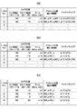
図4は、図2の処理によってメモリ106に保存されたプリセット情報を示す図であり、(a)は2つのプリセットが設定された場合を示し、(b)は3つのプリセットが設定された場合を示し、(c)は4つのプリセットが設定された場合を示す。
4A and 4B are diagrams showing preset information stored in the
図4(a)〜(c)において、補正用画像数(ステップS304における所定数M)=2とし、通常モードにおいてプリセット情報を保持しているものとする。 4A to 4C, it is assumed that the number of correction images (predetermined number M in step S304) = 2 and that preset information is held in the normal mode.
図4(a)では、プリセットNO.1とプリセットNO.2に、パン、チルトの角度情報、補正用画像、及びその補正用画像に対応したマッチングエリア情報が保存されている。プリセット数Nが所定数M=2より少ないので、ワイド端、テレ端、プリセット位置の3つの画像がすべて登録されている。マッチングエリアの欄に記載の英字は、pがプリセット画像(IMn_p)、wはワイド画像(IMn_w)、tはテレ画像(IMn_t)に対応し、引数は画像のエリアを示す。すなわちP(13)は、プリセット位置の画像において、エリア13がマッチングエリアであるということを示す。
In FIG. 4A, preset NO. 1 and preset NO. 2 stores pan and tilt angle information, a correction image, and matching area information corresponding to the correction image. Since the preset number N is smaller than the predetermined number M = 2, all three images of the wide end, the tele end, and the preset position are registered. As for the alphabetical characters described in the matching area column, p corresponds to the preset image (IMn_p), w corresponds to the wide image (IMn_w), t corresponds to the tele image (IMn_t), and the argument indicates the area of the image. That is, P (13) indicates that the
図4(b)において、プリセットNO.3のズーム情報は×8倍であり、他のプリセット情報と比較してテレ端からもワイド端からも2番目であるので、保持する補正用画像はテレ端、ワイド端、プリセット位置の3つの画像となる。一方、テレ端から3番目のプリセットNO.1のテレ画像の情報は消去され、ワイドから3番目のプリセットNO2.のワイド画像の情報も消去される。 In FIG. 4B, preset NO. The zoom information of 3 is × 8 times and is the second from the tele end and the wide end as compared with the other preset information, so the correction image to be held is the tele end, wide end, and preset position. It becomes an image. On the other hand, the third preset NO. 1 tele-image information is erased and the third preset No. 2 from wide is selected. The information of the wide image is also deleted.
さらに、図4(c)において、プリセットNO.4のズーム情報は×18倍であり、他のプリセット情報と比較してワイド端から4番目であるので、保持する補正用画像はテレ画像とプリセット位置の画像の2つとなる。一方、テレ端から3番目のプリセットNO.3のテレ画像の情報が消去される。 Further, in FIG. The zoom information of No. 4 is × 18 times and is the fourth from the wide end compared to the other preset information, so the correction images to be held are the tele image and the image at the preset position. On the other hand, the third preset NO. 3 tele-image information is erased.
以上のように、全プリセットのどこかで、設定したM=2の値と等しい数のテレ画像とワイド画像が補正用画像として保存される。このようなプリセット情報を有する監視カメラ113において、ユーザ操作によってプリセット位置の巡回プログラムをセットするなどし、プリセット位置へ移動してプリセット位置ずれの補正などを行う。
As described above, a number of tele images and wide images equal to the set value of M = 2 are stored as correction images somewhere in all the presets. In the
図5は、図1におけるCPU110によって実行される位置ずれ補正処理のフローチャートである。
FIG. 5 is a flowchart of misalignment correction processing executed by the
図5において、カメラユニット100は、ユーザ操作やタイマーのプログラムなどによって、前述したような事前に登録されたプリセット位置へ移動命令が発行されて、プリセット情報に基づいてパン・チルト駆動、ズーム駆動されたものとする。直後、CPU110は、メモリ106にプリセット位置の補正用画像が保存されているか否かを判別する(ステップS402)。
In FIG. 5, the
ステップS402の判別の結果、補正用画像メモリ104にプリセット位置の補正用画像が保存されていないときは、本処理を終了する。一方、ステップS402の判別の結果、補正用画像メモリ104にプリセット位置の補正用画像が保存されているときは、ステップS403に進む。ステップS403では、CPU110は、カメラ信号処理回路101から得られる現在の撮像画像(IM_T)と比較する比較画像として、プリセット位置画像IMn_pを選択する。
As a result of the determination in step S402, when the correction image at the preset position is not stored in the
次に、画像処理回路103は、この2つの比較画像、すなわちプリセット位置画像IMn_pと現在の撮像画像(IM_T)のそれぞれの画像に縮小処理を行う(ステップS404)。
Next, the
次に、画像比較処理回路105は、これらの縮小処理された画像に画像マッチング処理を行い、2つの画像の一致性を計算し、2つの画像の画素ずれにあたるグローバルベクトルを算出する(ステップS405)。つまり、画像比較処理回路105は第1の比較を行うことになる。
Next, the image
次に、CPU110は、このグローバルベクトルが検出されたか否かを判別する(ステップS406)。ステップS406の判別の結果、グローバルベクトルが検出されないときは、縮小処理された画像に相関がほとんどないので、ステップS407に進む。
Next, the
ステップS407では、CPU110は、現在のプリセット位置において補正用のワイド画像(IMn_w)が補正用画像メモリ104に保存されているか否かを判別する。この判別の結果、補正用のワイド画像(IMn_w)が補正用画像メモリ104に保存されているときは、比較画像をワイド画像に変更すると共に、ズームをワイド端へ駆動し(ステップS408)、ステップS404に戻る。ステップS404以降の処理により、このプリセット位置におけるワイド画像同士を比較する(つまり、第2の比較が行われることになる)。
In step S407, the
ステップS407の判別の結果、現在のプリセット位置において補正用のワイド画像(IMn_w)がステップS404保存されていないときは、本処理を終了する。もちろん、ワイド端でも画像のずれが検出しきれないほどにずれが生じているということで、パン・チルト位置のリセット動作を強制的に行うようにしてもよい。 If the result of determination in step S407 is that the correction wide image (IMn_w) has not been stored in step S404 at the current preset position, this processing ends. Of course, the pan / tilt position resetting operation may be forcibly performed because the image has been shifted so that the image cannot be detected even at the wide end.
ステップS406の判別の結果、グローバルベクトルが検出されたときは、CPU110は、比較対象の補正用画像からマッチングエリアを選択する(ステップS409)。次に、CPU110は、このマッチングエリアの画像情報と現在の撮像画像(IM_T)情報を比較する画像マッチング処理を行う(ステップS410)。このとき、CPU110は、ステップS406で検出されたグローバルベクトル方向へ画像を動かしながらマッチング処理を行う。
If a global vector is detected as a result of the determination in step S406, the
図6は、図5のステップS410の画像マッチング処理を説明する図であり、(a)は撮像画像及び補正用画像を示し、(b)は撮像画像を示す。 6A and 6B are diagrams for explaining the image matching process in step S410 in FIG. 5, in which FIG. 6A shows a captured image and a correction image, and FIG. 6B shows a captured image.
図6(a)において、実線で表された部分は、プリセット登録時に補正用画像メモリ104に保存した補正用画像IMn_xである。また、二点鎖線で囲まれた部分は、再びこのプリセット位置に駆動されてきたときにカメラ信号処理回路101から得られる撮影画像IM_Tである。図6(a)は、プリセット位置がモータの脱腸や衝突、地震等でずれてしまった例を示している。
In FIG. 6A, the portion indicated by a solid line is the correction image IMn_x stored in the
点線と実線のずれかたは、ステップS405において縮小処理された画像で検出した画像マッチングからグローバルベクトルGとして、概略には検出されている。また、この時の補正用画像IMn_xのマッチングエリアは、破線で囲まれた領域であるとする。このマッチングエリアは、画素の位置(i、j)から位置(i+p、j+q)を対角とする長方形で設定されている。また、ここでは画素(i、j)の輝度情報をY(i、j)としている。 The deviation between the dotted line and the solid line is roughly detected as a global vector G from the image matching detected in the image reduced in step S405. The matching area of the correction image IMn_x at this time is assumed to be an area surrounded by a broken line. This matching area is set as a rectangle whose diagonal is the position (i + p, j + q) from the pixel position (i, j). Here, the luminance information of the pixel (i, j) is Y (i, j).
図6(b)は、撮像画像IM_T の外枠を実線で示し、グローバルベクトルG、マッチングエリア、及び画像マッチングのサーチエリアの関係を示している。撮像画像IM_Tのうち、補正用画像のマッチングエリアに相当するエリア(i、j)をグローバルベクトルG分加算した位置、すなわち{(i、j)+G} と{(i+p、j+q)+G}を対角とするエリアがサーチエリアとして定められる。画像比較処理回路105は、このサーチエリア内のすべての範囲で、マッチングエリアとサーチエリアの輝度情報及び色情報の相関度を算出する。
FIG. 6B shows the outer frame of the captured image IM_T with a solid line, and shows the relationship between the global vector G, the matching area, and the search area for image matching. In the captured image IM_T, a position obtained by adding the area (i, j) corresponding to the matching area of the correction image by the global vector G, that is, {(i, j) + G} and {(i + p, j + q) + G} A corner area is defined as a search area. The image
マッチングエリアとサーチエリアの相関度は、対応する画素の輝度情報及び色情報の差分を全エリアに渡って積分した値の逆数で与えられる。すなわち、マッチングエリアとサーチエリアの輝度情報の相関度ΣYは、以下の数1によって表される。
The degree of correlation between the matching area and the search area is given by the reciprocal of the value obtained by integrating the luminance information and color information of the corresponding pixel over the entire area. That is, the degree of correlation ΣY between the luminance information of the matching area and the search area is expressed by the following

また、色情報からも同様にマッチングエリアとサーチエリアの相関度が算出される。色情報1から得られる相関度をΣC1、色情報2から得られる相関度をΣC2とすると、マッチングエリアとサーチエリアの相関度は、以下の数2によって表される。
Similarly, the correlation degree between the matching area and the search area is calculated from the color information. When the correlation degree obtained from the
![]()
![]()
図7は、図6の画像マッチング処理で算出されるマッチングエリアとサーチエリアの相関度の一例を示す図であり、(a)はピークが存在しない場合を示し、(b)はピークHが存在する場合を示し、(c)はピークHが0である場合を示す。 FIG. 7 is a diagram illustrating an example of the correlation degree between the matching area and the search area calculated by the image matching process in FIG. 6, (a) shows a case where no peak exists, and (b) shows a peak H exists. (C) shows the case where the peak H is zero.
図7(a)〜(c)において、横軸はサーチエリア内への画素ずらし量を示し、縦軸はマッチングエリアとサーチエリアの相関度を示す。 7A to 7C, the horizontal axis indicates the pixel shift amount into the search area, and the vertical axis indicates the degree of correlation between the matching area and the search area.
図7(a)では、マッチングエリアとサーチエリアの相関度が、どの画像ずらし量においても閾値Sを超えず、低い状態である。図5のステップS406において、グローバルベクトルが検出されている場合にはこのような状態にはならない。ただし、グローバルベクトルの検出時にも同様な手法で評価するが、この閾値Sを超えないような時には、ステップS406のグローバルベクトル検出時にグローバルベクトルが不明であると判別される。 In FIG. 7A, the degree of correlation between the matching area and the search area does not exceed the threshold value S at any image shift amount, and is in a low state. In step S406 in FIG. 5, such a state does not occur when a global vector is detected. However, although the same method is used for evaluation when a global vector is detected, when the threshold value S is not exceeded, it is determined that the global vector is unknown when the global vector is detected in step S406.
図7(b)では、サーチエリアで画素ずらしを行いマッチングエリアとサーチエリアの相関度を求めていくと、閾値Sを超えたピークHが見つかる。このときの画像ずらし量がピーク値Hの位置として計算される。 In FIG. 7B, when the pixel shift is performed in the search area and the correlation between the matching area and the search area is obtained, a peak H exceeding the threshold S is found. The image shift amount at this time is calculated as the position of the peak value H.
図7(c)では、画素ずらしを行わない位置にマッチングエリアとサーチエリアの相関度のピーク値Hがある。即ち、マッチングエリアとサーチエリアの画素ずれがない。この場合も、ステップS406のグローバルベクトル検出時にグローバルベクトルが無いと判別される。 In FIG. 7C, there is a peak value H of the degree of correlation between the matching area and the search area at a position where pixel shifting is not performed. That is, there is no pixel shift between the matching area and the search area. Also in this case, it is determined that there is no global vector when the global vector is detected in step S406.
以上のようにして、マッチングエリアとサーチエリアの画像ずれが、ピーク値Hに対応する画素ずらし量として検出される。この画素ずらし量を焦点距離から逆算して、パン・チルトの駆動量に変換する。 As described above, the image shift between the matching area and the search area is detected as the pixel shift amount corresponding to the peak value H. The pixel shift amount is calculated backward from the focal length and converted into a pan / tilt drive amount.
図5のフローチャートに戻り、ステップS410において、CPU110は、画像マッチングの後に、パン・チルトの駆動量を算出する。次に、算出された駆動量に基づいてパン・チルト制御回路108によりパン・チルト駆動を行う(ステップS411)。次に、今回画像マッチングに使用した補正用画像よりもテレ端の補正用画像が補正用画像メモリ104に保存されているか否かを判別する(ステップS412)。
Returning to the flowchart of FIG. 5, in step S <b> 410, the
ステップS412の判別の結果、テレ端の補正用画像が補正用画像メモリ104に保存されていないときは、本処理を終了する。一方、ステップS412の判別の結果、テレ端の補正用画像が補正用画像メモリ104に保存されているときは、比較画像をテレ画像に変更すると共に、ズームをテレ端へ駆動し(ステップS413)、ステップS404へ戻る(これによって、第2の比較が行われることになる)。
If the correction image at the telephoto end is not stored in the
以上のようなシーケンスをもって、プリセット位置がずれた場合に、所定の焦点距離とは焦点距離の異なる補正用画像と、対応する撮像画像とを比較し(第2の比較)、画像のずれに応じてプリセット位置ずれの補正を行うことができる。また、焦点距離の異なる補正用画像を保持しているので、少しのズーム駆動でプリセット位置ずれの補正を行うことができる。 With a sequence as described above, when the preset position is shifted, compared with the correction image having a different focal length and a predetermined focal length, and a corresponding captured image (second comparison), depending on the deviation of the image Thus, the preset position deviation can be corrected. Further, since the correction images having different focal lengths are held, the preset position deviation can be corrected with a little zoom drive.
本発明によれば、プリセット情報の登録時に、プリセットのパン・チルト位置において、焦点距離を変更してテレ端とワイド端の補正用画像を補正用画像メモリ104に保存する。これにより、テレ端の補正用画像を使用して位置ずれの微調整を行い、ワイド端の補正用画像を使用して祖調整を行うことができる。即ち、カメラユニット100がプリセット位置から大幅にずれた時や、微小にずれた時の双方に対応することができ、補正の精度及び確実性を向上させることができる。また、複数のプリセット情報を比較して、各プリセット位置で最適な焦点距離の補正用画像を補正用画像メモリ104に保存するので、補正用画像を保持するメモリリソースを少なくすると共に高度な補正を行うことができる。
According to the present invention, at the time of preset information registration, the focal length is changed at the preset pan / tilt positions, and the tele end and wide end correction images are stored in the
上記の実施の形態で説明した処理、機能等は、いずれもコンピュータで読み取り可能なプログラム等で実現することもできる。 Any of the processes, functions, and the like described in the above embodiments can be realized by a computer-readable program or the like.
この場合、上記の実施の形態で説明した処理、機能等は、システム又は装置に含まれるコンピュータ(CPU、MPU等でもよい)が上記のプログラム等を実行することによって実現されることになる。言い換えれば、上記のプログラム等が、システム又は装置に含まれるコンピュータに、上記の実施の形態で説明した処理、機能等を実行させることになる。また、この場合、上記のプログラム等は、コンピュータで読み取り可能な記憶媒体又はネットワークを介してシステム又は装置に含まれるコンピュータに提供されることになる。 In this case, the processes, functions, and the like described in the above embodiments are realized when a computer (CPU, MPU, or the like) included in the system or apparatus executes the above programs. In other words, the above-described program or the like causes the computer included in the system or apparatus to execute the processes and functions described in the above-described embodiment. In this case, the above-described program or the like is provided to a computer included in the system or apparatus via a computer-readable storage medium or a network.
システム又は装置に含まれるコンピュータに上記のプログラム等を提供する記憶媒体には、磁気ディスク、光ディスク、光磁気ディスク、ハードディスク、磁気テープ、不揮発性メモリ等を用いることができる。 A magnetic disk, an optical disk, a magneto-optical disk, a hard disk, a magnetic tape, a nonvolatile memory, or the like can be used as a storage medium that provides the above-described program or the like to a computer included in the system or apparatus.
また、上記のプログラム等は、その一部をコンピュータ上で稼動しているOS(オペレーティングシステム)等を用いて構成してもよい。 Moreover, you may comprise a part of said program etc. using OS (operating system) etc. which are operate | moving on the computer.
さらに、上記のプログラム等は、その一部をコンピュータに挿入された機能拡張ボードやコンピュータに接続された機能拡張ユニットで実行するように構成してもよい。 Furthermore, a part of the above-described program may be executed by a function expansion board inserted into the computer or a function expansion unit connected to the computer.
100 カメラユニット
101 カメラ信号処理回路
104 補正用画像メモリ
105 画像比較処理回路
108 パン・チルト制御回路
110 CPU
100
Claims (10)
前記撮像手段を駆動する駆動手段と、
前記撮像手段を所定の撮像位置及び所定の焦点距離の状態として撮像するためのプリセット情報を保持する第1の保持手段と、
前記プリセット情報が示す所定の撮像位置において前記撮像手段によって撮像され、その焦点距離が互いに異なる複数の補正用画像を保持する第2の保持手段と、
前記プリセット情報で示す所定の撮像位置及び所定の焦点距離に駆動する指示を受けると、前記撮像手段を前記所定の撮像位置及び前記所定の焦点距離に駆動して撮像された画像と、前記撮像手段が前記所定の撮像位置及び前記所定の焦点距離とされた際の補正用画像とを比較する第1の比較と、前記撮像手段を前記所定の撮像位置とし前記所定の焦点距離とは異なる焦点距離として撮像された画像と、前記撮像手段が前記所定の撮像位置とされ前記異なる焦点距離とされた際の補正用画像とを比較する第2の比較とを行って、前記第1及び前記第2の比較の結果得られた第1及び第2の比較結果に基づいて前記駆動手段の駆動量を制御する制御手段とを有することを特徴とする撮像装置。 An imaging means for capturing an image;
Driving means for driving the imaging means;
First holding means for holding preset information for imaging the imaging unit as a state of a predetermined imaging position and a predetermined focal length;
A second holding unit that holds a plurality of correction images that are captured by the imaging unit at a predetermined imaging position indicated by the preset information and that have different focal lengths;
Upon receiving an instruction to drive to a predetermined imaging position and a predetermined focal length indicated by the preset information, an image captured by driving the imaging unit to the predetermined imaging position and the predetermined focal distance, and the imaging unit A first comparison comparing the predetermined imaging position and the correction image when the predetermined focal distance is set, and a focal length different from the predetermined focal distance with the imaging means as the predetermined imaging position And a second comparison for comparing the correction image when the imaging means is at the predetermined imaging position and the different focal length, and the first and second An image pickup apparatus comprising: control means for controlling the drive amount of the drive means based on the first and second comparison results obtained as a result of the comparison.
メモリに前記撮像手段を所定の撮像位置及び所定の焦点距離の状態として撮像するためのプリセット情報を保持する第1の保持工程と、
メモリに前記プリセット情報が示す所定の撮像位置において前記撮像手段によって撮像され、その焦点距離が互いに異なる複数の補正用画像を保持する第2の保持工程と、
前記プリセット情報で示す所定の撮像位置及び所定の焦点距離に駆動する指示を受けると、前記撮像手段を前記所定の撮像位置及び前記所定の焦点距離に駆動して撮像された画像と、前記撮像手段が前記所定の撮像位置及び前記所定の焦点距離とされた際の補正用画像とを比較する第1の比較工程と、
前記撮像手段を前記所定の撮像位置とし前記所定の焦点距離とは異なる焦点距離として撮像された画像と、前記撮像手段が前記所定の撮像位置とされ前記異なる焦点距離とされた際の補正用画像とを比較する第2の比較工程と、
前記第1及び前記第2の比較工程でそれぞれ得られた第1及び第2の比較結果に基づいて前記駆動手段の駆動量を制御する制御工程とを有することを特徴とする撮像装置の制御方法。 In a control method for an image pickup apparatus comprising an image pickup means for picking up an image and a drive means for driving the image pickup means,
A first holding step for holding preset information for imaging the imaging unit in a memory as a state of a predetermined imaging position and a predetermined focal length;
A second holding step of holding a plurality of correction images captured by the imaging unit at a predetermined imaging position indicated by the preset information in a memory and having different focal lengths;
Upon receiving an instruction to drive to a predetermined imaging position and a predetermined focal length indicated by the preset information, an image captured by driving the imaging unit to the predetermined imaging position and the predetermined focal distance, and the imaging unit A first comparison step of comparing the correction image when the predetermined imaging position and the predetermined focal length are set;
An image captured with the imaging means as the predetermined imaging position and a focal distance different from the predetermined focal distance, and a correction image when the imaging means is at the predetermined imaging position and the different focal distance A second comparison step for comparing
And a control step of controlling the drive amount of the drive means based on the first and second comparison results obtained in the first and second comparison steps, respectively. .
メモリに前記撮像手段を所定の撮像位置及び所定の焦点距離の状態として撮像するためのプリセット情報を保持する第1の保持工程と、
メモリに前記プリセット情報が示す所定の撮像位置において前記撮像手段によって撮像され、その焦点距離が互いに異なる複数の補正用画像を保持する第2の保持工程と、
前記プリセット情報で示す所定の撮像位置及び所定の焦点距離に駆動する指示を受けると、前記撮像手段を前記所定の撮像位置及び前記所定の焦点距離に駆動して撮像された画像と、前記撮像手段が前記所定の撮像位置及び前記所定の焦点距離とされた際の補正用画像とを比較する第1の比較工程と、
前記撮像手段を前記所定の撮像位置とし前記所定の焦点距離とは異なる焦点距離として撮像された画像と、前記撮像手段が前記所定の撮像位置とされ前記異なる焦点距離とされた際の補正用画像とを比較する第2の比較工程と、
前記第1及び前記第2の比較工程でそれぞれ得られた第1及び第2の比較結果に基づいて前記駆動手段の駆動量を制御する制御工程とを有することを特徴とするプログラム。 In a program for causing a computer to execute a control method for controlling an image pickup apparatus including an image pickup unit that picks up an image and a drive unit that drives the image pickup unit, the control method includes:
A first holding step for holding preset information for imaging the imaging unit in a memory as a state of a predetermined imaging position and a predetermined focal length;
A second holding step of holding a plurality of correction images captured by the imaging unit at a predetermined imaging position indicated by the preset information in a memory and having different focal lengths;
Upon receiving an instruction to drive to a predetermined imaging position and a predetermined focal length indicated by the preset information, an image captured by driving the imaging unit to the predetermined imaging position and the predetermined focal distance, and the imaging unit A first comparison step of comparing the correction image when the predetermined imaging position and the predetermined focal length are set;
An image captured with the imaging means as the predetermined imaging position and a focal distance different from the predetermined focal distance, and a correction image when the imaging means is at the predetermined imaging position and the different focal distance A second comparison step for comparing
And a control step of controlling the drive amount of the drive means based on the first and second comparison results obtained in the first and second comparison steps, respectively.
Priority Applications (3)
| Application Number | Priority Date | Filing Date | Title |
|---|---|---|---|
| JP2007177632A JP4948294B2 (en) | 2007-07-05 | 2007-07-05 | Imaging apparatus, imaging apparatus control method, and program |
| US12/142,033 US7965935B2 (en) | 2007-07-05 | 2008-06-19 | Control device and method for camera unit and program for implementing the control method |
| CN2008101080652A CN101340517B (en) | 2007-07-05 | 2008-07-04 | Control device and method for camera unit |
Applications Claiming Priority (1)
| Application Number | Priority Date | Filing Date | Title |
|---|---|---|---|
| JP2007177632A JP4948294B2 (en) | 2007-07-05 | 2007-07-05 | Imaging apparatus, imaging apparatus control method, and program |
Publications (3)
| Publication Number | Publication Date |
|---|---|
| JP2009017302A JP2009017302A (en) | 2009-01-22 |
| JP2009017302A5 JP2009017302A5 (en) | 2010-08-19 |
| JP4948294B2 true JP4948294B2 (en) | 2012-06-06 |
Family
ID=40214460
Family Applications (1)
| Application Number | Title | Priority Date | Filing Date |
|---|---|---|---|
| JP2007177632A Active JP4948294B2 (en) | 2007-07-05 | 2007-07-05 | Imaging apparatus, imaging apparatus control method, and program |
Country Status (3)
| Country | Link |
|---|---|
| US (1) | US7965935B2 (en) |
| JP (1) | JP4948294B2 (en) |
| CN (1) | CN101340517B (en) |
Families Citing this family (6)
| Publication number | Priority date | Publication date | Assignee | Title |
|---|---|---|---|---|
| JP5340895B2 (en) * | 2009-11-24 | 2013-11-13 | 株式会社ソニー・コンピュータエンタテインメント | Image data creation support apparatus and image data creation support method |
| TWI426775B (en) * | 2010-12-17 | 2014-02-11 | Ind Tech Res Inst | Camera recalibration system and the method thereof |
| US20160191658A1 (en) * | 2013-03-15 | 2016-06-30 | Instart Logic, Inc. | Efficient delivery of webpages |
| CN104349035A (en) * | 2013-07-25 | 2015-02-11 | 宏碁股份有限公司 | Image capturing equipment and method |
| US10612939B2 (en) | 2014-01-02 | 2020-04-07 | Microsoft Technology Licensing, Llc | Ground truth estimation for autonomous navigation |
| CN113724312A (en) * | 2021-08-13 | 2021-11-30 | 辽宁四季环境治理工程有限公司 | Real-time monitoring and early warning method and device for geological disasters |
Family Cites Families (12)
| Publication number | Priority date | Publication date | Assignee | Title |
|---|---|---|---|---|
| US6985177B2 (en) * | 2000-07-04 | 2006-01-10 | Canon Kabushiki Kaisha | Image sensing system and its control method |
| JP2002116367A (en) * | 2000-08-01 | 2002-04-19 | Canon Inc | Lens position control device and optical apparatus |
| WO2002080521A2 (en) * | 2001-03-30 | 2002-10-10 | Digeo, Inc. | System and method for a software steerable web camera with multiple image subset capture |
| JP2003058884A (en) * | 2001-08-13 | 2003-02-28 | Nippon Signal Co Ltd:The | Object presence density measuring instrument |
| JP2003098576A (en) * | 2001-09-26 | 2003-04-03 | Fuji Photo Optical Co Ltd | Pan head device |
| US20050196070A1 (en) * | 2003-02-28 | 2005-09-08 | Fujitsu Limited | Image combine apparatus and image combining method |
| EP1641246A4 (en) * | 2003-06-17 | 2010-08-18 | Panasonic Corp | Information generating apparatus, image pickup apparatus and image pickup method |
| GB2411532B (en) * | 2004-02-11 | 2010-04-28 | British Broadcasting Corp | Position determination |
| JP4522207B2 (en) * | 2004-09-17 | 2010-08-11 | キヤノン株式会社 | Camera system, camera body and interchangeable lens |
| JP2007019776A (en) * | 2005-07-07 | 2007-01-25 | Matsushita Electric Ind Co Ltd | Imaging system |
| US7839431B2 (en) * | 2006-10-19 | 2010-11-23 | Robert Bosch Gmbh | Image processing system and method for improving repeatability |
| JP4776503B2 (en) * | 2006-11-13 | 2011-09-21 | 富士フイルム株式会社 | Remote head system |
-
2007
- 2007-07-05 JP JP2007177632A patent/JP4948294B2/en active Active
-
2008
- 2008-06-19 US US12/142,033 patent/US7965935B2/en active Active
- 2008-07-04 CN CN2008101080652A patent/CN101340517B/en active Active
Also Published As
| Publication number | Publication date |
|---|---|
| JP2009017302A (en) | 2009-01-22 |
| CN101340517A (en) | 2009-01-07 |
| US20090010634A1 (en) | 2009-01-08 |
| US7965935B2 (en) | 2011-06-21 |
| CN101340517B (en) | 2012-10-17 |
Similar Documents
| Publication | Publication Date | Title |
|---|---|---|
| JP4695972B2 (en) | Image processing apparatus, imaging apparatus, and image processing method | |
| JP4843002B2 (en) | IMAGING DEVICE, IMAGING DEVICE CONTROL METHOD, AND COMPUTER PROGRAM | |
| US8619120B2 (en) | Imaging apparatus, imaging method and recording medium with program recorded therein | |
| JP4730478B2 (en) | IMAGING DEVICE, IMAGING DEVICE CONTROL METHOD, AND PROGRAM | |
| WO2004066631A1 (en) | Monitoring device and monitoring method using panorama image | |
| JP4948294B2 (en) | Imaging apparatus, imaging apparatus control method, and program | |
| JP2016066978A (en) | Imaging device, and control method and program for the same | |
| JP2010096962A (en) | Auto focus system with af frame auto-tracking function | |
| US8373773B2 (en) | Imaging apparatus for generating a wide-angle image | |
| JP5247338B2 (en) | Image processing apparatus and image processing method | |
| JP4807582B2 (en) | Image processing apparatus, imaging apparatus, and program thereof | |
| JP6362310B2 (en) | IMAGING DEVICE, IMAGING SYSTEM, IMAGING DEVICE CONTROL METHOD, PROGRAM, AND STORAGE MEDIUM | |
| JP2007049266A (en) | Picture imaging apparatus | |
| JP5034880B2 (en) | Electronic camera, image display device | |
| JP2019092036A (en) | Imaging apparatus and control method | |
| JP5744527B2 (en) | Imaging apparatus and control method thereof | |
| JP2000101901A (en) | Image pickup device and method therefor, image pickup device control system and storage medium | |
| JP6836306B2 (en) | Imaging control device, its control method, program and recording medium | |
| JP2010062834A (en) | Photographing system, photographing device constituting the same, and operation device | |
| JP6395513B2 (en) | Imaging apparatus, control method therefor, program, and storage medium | |
| JP4495028B2 (en) | Camera device and surveillance camera system | |
| JP2005100388A (en) | Object tracking method | |
| JP2012039178A (en) | Imaging apparatus, exposure control method and program | |
| JP2008035130A (en) | Imaging apparatus, and its control method | |
| JP2017216599A (en) | Imaging apparatus and control method therefor |
Legal Events
| Date | Code | Title | Description |
|---|---|---|---|
| A521 | Request for written amendment filed |
Free format text: JAPANESE INTERMEDIATE CODE: A523 Effective date: 20100701 |
|
| A621 | Written request for application examination |
Free format text: JAPANESE INTERMEDIATE CODE: A621 Effective date: 20100701 |
|
| A977 | Report on retrieval |
Free format text: JAPANESE INTERMEDIATE CODE: A971007 Effective date: 20110914 |
|
| A131 | Notification of reasons for refusal |
Free format text: JAPANESE INTERMEDIATE CODE: A131 Effective date: 20111108 |
|
| A521 | Request for written amendment filed |
Free format text: JAPANESE INTERMEDIATE CODE: A523 Effective date: 20120110 |
|
| TRDD | Decision of grant or rejection written | ||
| A01 | Written decision to grant a patent or to grant a registration (utility model) |
Free format text: JAPANESE INTERMEDIATE CODE: A01 Effective date: 20120207 |
|
| A01 | Written decision to grant a patent or to grant a registration (utility model) |
Free format text: JAPANESE INTERMEDIATE CODE: A01 |
|
| A61 | First payment of annual fees (during grant procedure) |
Free format text: JAPANESE INTERMEDIATE CODE: A61 Effective date: 20120306 |
|
| FPAY | Renewal fee payment (event date is renewal date of database) |
Free format text: PAYMENT UNTIL: 20150316 Year of fee payment: 3 |
|
| R151 | Written notification of patent or utility model registration |
Ref document number: 4948294 Country of ref document: JP Free format text: JAPANESE INTERMEDIATE CODE: R151 |
|
| FPAY | Renewal fee payment (event date is renewal date of database) |
Free format text: PAYMENT UNTIL: 20150316 Year of fee payment: 3 |