JP4948192B2 - Indoor door locks - Google Patents
Indoor door locks Download PDFInfo
- Publication number
- JP4948192B2 JP4948192B2 JP2007026228A JP2007026228A JP4948192B2 JP 4948192 B2 JP4948192 B2 JP 4948192B2 JP 2007026228 A JP2007026228 A JP 2007026228A JP 2007026228 A JP2007026228 A JP 2007026228A JP 4948192 B2 JP4948192 B2 JP 4948192B2
- Authority
- JP
- Japan
- Prior art keywords
- base plate
- mounting base
- door
- display
- wall surface
- Prior art date
- Legal status (The legal status is an assumption and is not a legal conclusion. Google has not performed a legal analysis and makes no representation as to the accuracy of the status listed.)
- Active
Links
- 210000003813 thumb Anatomy 0.000 claims description 13
- 230000002093 peripheral effect Effects 0.000 claims description 9
- 230000008878 coupling Effects 0.000 description 5
- 238000010168 coupling process Methods 0.000 description 5
- 238000005859 coupling reaction Methods 0.000 description 5
- 238000010586 diagram Methods 0.000 description 3
- 230000000149 penetrating effect Effects 0.000 description 2
- 230000002265 prevention Effects 0.000 description 2
- 239000003086 colorant Substances 0.000 description 1
- 230000000694 effects Effects 0.000 description 1
- 238000000034 method Methods 0.000 description 1
- 239000011435 rock Substances 0.000 description 1
Images
Landscapes
- Lock And Its Accessories (AREA)
Description
本発明は、室内における扉用表示錠に関する。本発明は、特に、室内のトイレ、個室等の扉に適用される。 The present invention relates to an indoor door display lock. The present invention is particularly applied to doors of indoor toilets and private rooms.
図10は従来の環境説明図で、この環境説明図は、本発明との対比上、概念的に簡略化している。また、図11は室内の扉(例えばトイレ)の外壁面から見た外観上の説明図である。図10及び図11を参照にして、従来の表示錠の一例を説明する。 FIG. 10 is a diagram illustrating a conventional environment, and this environment diagram is conceptually simplified for comparison with the present invention. Moreover, FIG. 11 is explanatory drawing on the external appearance seen from the outer wall surface of the indoor door (for example, toilet). An example of a conventional display lock will be described with reference to FIGS. 10 and 11.
図10及び図11に於いて、1は表示錠Xが取付けられる引戸又は回転式の室内の扉(以下、「扉」という)。1aは扉1の外壁面、1bは扉1の内壁面である。扉1の中に仮想線で示した部材は、デッドボルトや鎌(以下、「施錠片」という)2を意味する。
また、扉1の内壁面1bに断面で示した部材は、内側の操作部材(以下、「サムターン」という)3用の固定筒4である。また、扉1の中に水平棒は、内外の操作部材用の連結軸5である。この連結軸5の内端部には前記内側のサムターン3が、サムターン駆動部材6を介して、又は介さないで連結され、一方、連結軸5の外端部には、外側の操作部材(以下、「解錠用操作軸」という)7が連結される。
10 and 11,
The member shown in cross section on the
付言すると、サムターン3の軸部3a、連結軸5及び解錠用操作軸7は、同軸上に位置することから、サムターン3又は解錠用操作軸7のいずれかを回転させると、操作部材の操作力により、施錠片2は、扉1の端面から進退動(施・解錠)する。ここでは、サムターン駆動部材6は、発明の要旨でないから、全体をボックスで示し、その詳細な説明を割愛している。
In other words, since the
なお、前記解錠用操作軸7と連結軸5は一つの部材であっても良い。また、サムターン駆動部材6はあっても、なくても良い。要は、サムターン3の軸部3aと解錠用操作軸7とが同一軸上に位置していれば良い。
The
さて、扉用表示錠Xを構成する主要部は、扉1の外壁面1aに突出した状態で取付けられている(図11参照)。
Now, the main part which comprises the display lock | rock X for doors is attached in the state protruded to the
すなわち、11は扉1の外壁面1aに複数本の固着具12を介して固定された円盤状の取付けベース板で、この中央部には、解錠用操作軸7用の中心孔(基準孔)13が形成されている。この取付けベース板11の前面には、例えば表示板用受け突起11aが、環状に周設され、或は複数個の小突起として設けられている。そして、取付けベース板11の受け突起11aよりもさらに外端部には、前記固着具12と螺合する取付け孔(通孔、メネジなど)14が形成されている。この取付け孔14には固着具12がそれぞれ貫通又は螺合する。
That is, 11 is a disk-like mounting base plate fixed to the
付言すると、浅いケース状のカバー15は、図10及び図11で示すように、上下に位置する固着具12等を介して取付けベース板11に固定されている。つまり、カバー15は、「外から」、不番の固着具用貫通孔を介して扉1の外壁面1aに固定されている。
扉1の外壁面1aに直接又は取付けベース板11を介して固定される円形カバー15は、その前壁15aの通孔の縁31の同心円状に弧状の表示窓16を有している。この表示窓16からは、解錠用操作軸7に一体的に固定された表示板18の文字、色彩、図柄等の識別情報が見える。
In other words, the shallow case-
The
円形の表示板18は取付けベース板11の前面とカバー15の前壁15aの内面との間に位置し、操作部材3、7と共に回転する。
The
上記構成に於いて、例えばカバー15の前壁15aは円形であること、カバー15は、頭部12aが外から見える固着具12を介して扉1の外壁面1aに固定されていること、カバー15の通孔の縁31に嵌合する解錠用操作軸7の外端部7aはコイン用係合溝(割溝)を有することから、コインの形状に合わせて比較的外形寸法が大きく形成されていること、固着具12は解錠用操作軸7の外端部7aの略真上に位置すると共に、前記外端部7aの周縁と固着具12との間(幅)は短いこと等の理由から、「表示窓16」並びに「表示板18」を大きくすることができなかった。
In the above configuration, for example, the
したがって、カバー15を小さくすればするほど、表示窓16から見える表示板18の識別情報が判り難いという問題があった。
Accordingly, there is a problem that the smaller the
ところで、特許文献1の段落0020と段落0021には、「二本の取付管11・12は、ドア1の厚み方向を貫通して室内側にのびており、その他端側のネジ孔に、サムターン5を取り付ける図示しない取付けネジが取り付けられている。前記ベース部材10の凹部10aには、表示プレート15が後記する回動部材16で支持されて収納されている」、と記載されている。
By the way, in paragraphs 00 20 and 0021 of
また、段落0030には、「そして、カバー部材23の取付状態では、円形窓孔23bを通して前記回動部材16の頭部16aおよび割溝16bがわずかに外部に突出した状態となっている」、と記載され、さらに、段落0031には、「しかして、表示錠4の解錠状態では、表示窓23cを通して前記表示プレート15の表示シート17が表示されている。一方、室内側でサムターン5を操作して施錠したときは、回動シャフト20が同時に回動するとともにそれと一体で表示プレート15が回動し、別の表示シート18が表示窓孔23cを通して表示される」、と記載されている。
In addition, the paragraph 0030 states that “the head member 16a and the split groove 16b of the rotating
しかしながら、特許文献1の表示錠の適用の場は、主として玄関扉(屋外から室内に入る所の扉)であることから、防犯性を考慮して、ベース部材10が玄関扉の外壁面側(室外側)から抜き取られないような固定構造となっている。すなわち、ベース部材10は、玄関扉の内壁面(サムターン5)側から二本の取付管11・12に対してネジ止めされている。
However, since the place where the display lock of
したがって、室内のトイレ、個室等の扉には適しない。何故ならば、普通一般に、この種の扉に適用する表示錠は、防犯性を考慮する必要性がない反面、扉の外壁面側から簡単に取付けることができることや取り外しができることが要望されているからである。特に、扉の外壁面側から表示錠を取り外しできることは、トイレ等で事故が発生した場合には重要である。
本発明の所期の目的は、室内における扉用表示錠に於いて、扉の外壁面に表示錠を、固着具を介して固定する場合、仮に、カバーの大きさが、従来のそれと同様であっても、「表示窓」並びに「表示板」を大きくすることができることである。本発明の第2の目的は、カバーの前壁の位置が扉の外壁面から極力突出しないことである。その他カバーを取付けベース板に簡単に結合することができることである。 The intended purpose of the present invention is to lock the display lock on the outer wall surface of the door with a fastener in the indoor door display lock. Even so, the “display window” and the “display board” can be enlarged. The second object of the present invention is that the position of the front wall of the cover does not protrude as much as possible from the outer wall surface of the door. In addition, the cover can be easily coupled to the mounting base plate.
本発明の室内における扉用表示錠は、室内の扉の外壁面に固着具を介して固定される部材が、取付けベース板と、この取付けベース板の基準孔を貫通する解錠用操作軸に一体的に設けられかつ表面に識別情報を含む表示板をそれぞれカバーするケース状のカバーであり、また、室内側のサムターンの軸部と室外側の解錠用操作軸とが同一軸上に位置すると共に、前記解錠用操作軸の外端部の周縁と前記固着具の頭部との間に前記識別情報を外部に見せる表示窓が前記カバーの前壁に形成されている室内における扉用表示錠に於いて、前記固着具は、その頭部が表示窓の裏側でかつ前記取付けベース板の前面に形成された横向き凹所内に位置した状態で取付けベース板を扉の外壁面に該外壁面側から固定し、また前記表示板の周端部は前記取付けベース板の前面を該前面に支持された状態で覆い、さらに前記カバーは係合手段により取付けベース板に結合していることを特徴とする。 In the indoor door lock according to the present invention, the member fixed to the outer wall surface of the indoor door via a fixing member is attached to the mounting base plate and the unlocking operation shaft penetrating the reference hole of the mounting base plate. a case-like cover covering panels each including identification information to the integrally provided and the surface, also located on the same axis and the shaft portion of the indoor-side thumb-turn and the outdoor side of the unlocking operation shaft And a door for a door in a room in which a display window is formed on the front wall of the cover between the periphery of the outer end of the unlocking operation shaft and the head of the fixing tool. in view tablets, said fastener, said outside the mounting base plate on the outer wall surface of the door with its head located within transverse recess formed in the front surface of the back side a and the mounting base plate of the display window fixed from the wall surface side, the peripheral edge portion of the panel is the mounting Covered in a state where the front is supported on the front surface of the base plate, further wherein the cover is characterized in that attached to the mounting base plate by engagement means.
また本発明の室内における扉用表示錠は、室内の扉の外壁面に固着具を介して固定される部材が、取付けベース板と、この取付けベース板の基準孔を貫通する解錠用操作軸に一体的に設けられかつ表面に識別情報を含む表示板をそれぞれカバーするケース状のカバーであり、また、室内側のサムターンの軸部と室外側の解錠用操作軸とが同一軸上に位置すると共に、前記解錠用操作軸の外端部の周縁と前記固着具の頭部との間に前記識別情報を外部に見せる表示窓が前記カバーの前壁に形成されている室内における扉用表示錠に於いて、前記固着具は、その頭部が表示窓の裏側でかつ前記取付けベース板の前面に形成された横向き凹所内に位置した状態で取付けベース板を扉の外壁面に該外壁面側から固定し、また前記表示板の周端部は前記取付けベース板の前面を該前面に支持された状態で覆い、さらに前記カバーは固着手段により取付けベース板に結合していることを特徴とする。 In the indoor door display lock according to the present invention, the member fixed to the outer wall surface of the indoor door via the fixing member includes the mounting base plate and the unlocking operation shaft through the reference hole of the mounting base plate. a display panel including the identification information provided and the surface integrally a case-like cover that covers respectively, also the indoor side of the shaft portion of the thumb-turn and the outdoor side of the unlocking operation shaft and is coaxially on the A door in a room that is positioned and has a display window formed on the front wall of the cover between the periphery of the outer end of the unlocking operation shaft and the head of the fastener. In the display lock for use, the mounting base plate is attached to the outer wall surface of the door in a state where the head is located in a lateral recess formed on the back side of the display window and on the front surface of the mounting base plate. fixed from the outer wall surface side, the peripheral edge portion of the panel is the With cover in a state where the front is supported on the front surface of the base plate, further wherein the cover is characterized in that attached to the mounting base plate by fixing means.
本発明は、室内における扉用表示錠に於いて、扉の外壁面に表示錠を、固着具を介して固定する場合、従来の実施例と比較して、「表示窓16A」並びに「表示板18A」を大きくすることができる。また、カバーの前壁の位置が扉の外壁面から極力突出しない。
In the case of an indoor door display lock, when the display lock is fixed to the outer wall surface of the door via a fixing tool, the
以下、図1乃至図9に示す本発明を実施するための最良の形態(第1実施例)により説明する。なお、従来例の構成と同一の部分には、同一(又は同様)の符号付して重複する説明を割愛する。以下、主に異なる事項を中心に説明する。 The best mode for carrying out the present invention shown in FIGS. 1 to 9 will be described below (first embodiment). In addition, the same (or similar) code | symbol is attached | subjected to the part same as the structure of a prior art example, and the overlapping description is omitted. In the following, mainly different items will be mainly described.
(1)取付けベース板11A
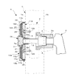
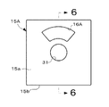
図1は発明の実施の環境を示す概略説明図である。この図1は従来例の図10に対応する。図2は扉の外壁面から見た外観上の説明図である。したがって、図2は従来例の図11に対応する。
(1)
FIG. 1 is a schematic explanatory diagram showing an environment for carrying out the invention. FIG. 1 corresponds to FIG. 10 of the conventional example. FIG. 2 is an explanatory view on the appearance as seen from the outer wall surface of the door. Therefore, FIG. 2 corresponds to FIG. 11 of the conventional example.
図1と図10とを対比すると明らかなように、本願発明の固着具12Aは、その頭部12aが表示窓16Aの裏側に位置した状態で取付けベース板11Aを扉1の外壁面1aに固定している(相違点1)。
As is clear from the comparison between FIG. 1 and FIG. 10, the fixing
また、取付けベース板11Aの前面には、固着具12Aの頭部12aが位置する横向き凹所21が形成されている。この横向き凹所21は、図4で示すように、矩形状肉厚の取付けベース板11Aの前面に円形状に形成され、かつ、取付けベース板11Aの中心孔13に連通している。上下一対の取付け孔14は、横向き凹所21の垂直内壁の中心孔13を垂直軸方向に通る中央部にそれぞれ形成されている。
Further, a
なお、取付けベース板11Aのやや肉厚状の環状外周部分22の表面には、周方向に所定間隔を有して小さな受け突起11aが設けられている。取付けベース板11Aの形状は、円形、四角形(本実施例)等である。その他、取付けベース板11Aに裏面に設けた新規事項は図面上省略している。
A
(2)表示板18A
ドーナツ形状の表示板18Aは、解錠用操作軸7Aに不番の係合手段を介して一体的に設けられている。本願発明の表示板18Aは、図1で示すように、取付けベース板11Aの前面を略覆うような大きさに形成されている(相違点2)。
(2)
The donut-shaped
また、図4で示すように、表示板18Aは、表示ベース板25と、この表示ベース板25の前面に張り付けられた表示シート26とから成り、前記表示シート26には、図3で示すように、周方向に、例えば「使用中、あき」の識別情報が付されている。なお、表示ベース板25及び表示シート26の縁部には、例えばオス・メスの位置決め手段25a、26aが適宜に設けられている。また、表示ベース板25及び表示シート26の中央部には、解錠用操作軸7A用の不番の通孔が形成されている。
As shown in FIG. 4, the
(3)カバー15A
図2と図11とを対比すると明らかなように、本願発明のケース状カバー15Aの前壁15aには、固着具用の取付け孔が形成されていない(相違点3)。したがって、前記前壁15aの表示窓16Aを大きく形成することができる(効果)。
付言すると、円形又は角形状(本実施例)の前壁15aの中央部に形成された解錠用操作軸7A用通孔の孔縁31と前壁15aの外縁32との間(幅)を、従来例のように固着具12が存在しない分だけ自由に表示窓して使用することができるから、表示窓16Aを大きく形成することができる。本発明の固着具12Aは、前述したように、ケース状カバー15Aの中に位置する。
(3)
As is clear from the comparison between FIG. 2 and FIG. 11, no attachment hole for the fixing tool is formed in the
In addition, the space (width) between the
(4)カバーの結合構造
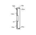
カバー15Aは、係合手段35により取付けベース板11Aに結合している。図8はその一例を示す。すなわち、カバー15Aの囲い方向の側壁15bの内壁面には、例えばテーパを有する係合突起35aが設けられ、一方、前記側壁15bに対面する取付けベース板11Aの側壁11bには、前記係合突起35aと係合する係合凹所35bが形成されている。カバーの結合構造が係合手段35の場合には、「ワンタッチ方式」により、カバー15Aが取付けベース板11Aに固定することができる。
(4) Cover coupling structure The
この欄では、念のために、本発明のカバーの結合構造の他の実施例を示す。なお、第1実施例と同一部分には符号を援用する。 In this section, another embodiment of the coupling structure of the cover of the present invention is shown just in case. In addition, a code | symbol is used for the same part as 1st Example.
図9に示す第2実施例のカバーの結合構造は、固着手段35Aである。すなわち、カバー15Aの囲い方向の側壁15bの内壁面には、固着具34A用の貫通孔35aが形成され、一方、前記側壁15bに対面する取付けベース板11Aの側壁11bには、前記固着具34A用のメネジ35bが形成されている。このように構成しても、第1実施例と同一の目的を達成することができる。
The cover coupling structure of the second embodiment shown in FIG. 9 is an adhering means 35A. That is, a through
本発明は、主に建具や錠前の業界で利用される。 The present invention is mainly used in the joinery and lock industry.
図1乃至図8は本発明の最良の第1実施例を示す各説明図。図9は本発明の要部を設計変更した他例を示す説明図、図10及び図11は従来例を示す各説明図。
X…表示錠、1…扉(扉)、1a…外壁面、1b…内壁面、2…施錠片、3…サムターン、3a…サムターンの軸部、4…固定筒、5…連結軸、7…解錠用操作軸、7a…操作軸の外端部、11、11A…取付けベース板、11b…側壁、12、12A…固着具、12a…固着具の頭部、13…中心孔、14…取付け孔(貫通状メネジ)、15、15A…カバー、15a…前壁、15b…側壁、16…表示窓、18、18A…表示板、21…横向き凹所、22…環状外周部分、25…表示ベース板、26…表示シート、25a、26a…位置決め手段、31…孔縁、32…カバーの外縁、35…係合手段、35A…固着手段。
X: Display lock, 1 ... Door (door), 1a ... Outer wall surface, 1b ... Inner wall surface, 2 ... Locking piece, 3 ... Thumb turn, 3a ... Shaft part of thumb turn, 4 ... Fixed cylinder, 5 ... Connecting shaft, 7 ... Operation shaft for unlocking, 7a ... Outer end of operation shaft, 11, 11A ... Mounting base plate, 11b ... Side wall, 12, 12A ... Fixing tool, 12a ... Head of fixing tool, 13 ... Center hole, 14 ... Mounting Hole (penetrating internal thread), 15, 15A ... cover, 15a ... front wall, 15b ... side wall, 16 ... display window, 18, 18A ... display plate, 21 ... lateral recess, 22 ... annular outer peripheral part, 25 ...
Claims (2)
Priority Applications (1)
| Application Number | Priority Date | Filing Date | Title |
|---|---|---|---|
| JP2007026228A JP4948192B2 (en) | 2007-02-06 | 2007-02-06 | Indoor door locks |
Applications Claiming Priority (1)
| Application Number | Priority Date | Filing Date | Title |
|---|---|---|---|
| JP2007026228A JP4948192B2 (en) | 2007-02-06 | 2007-02-06 | Indoor door locks |
Publications (3)
| Publication Number | Publication Date |
|---|---|
| JP2008190226A JP2008190226A (en) | 2008-08-21 |
| JP2008190226A5 JP2008190226A5 (en) | 2010-03-25 |
| JP4948192B2 true JP4948192B2 (en) | 2012-06-06 |
Family
ID=39750567
Family Applications (1)
| Application Number | Title | Priority Date | Filing Date |
|---|---|---|---|
| JP2007026228A Active JP4948192B2 (en) | 2007-02-06 | 2007-02-06 | Indoor door locks |
Country Status (1)
| Country | Link |
|---|---|
| JP (1) | JP4948192B2 (en) |
Families Citing this family (3)
| Publication number | Priority date | Publication date | Assignee | Title |
|---|---|---|---|---|
| JP5592099B2 (en) * | 2009-11-11 | 2014-09-17 | ミサワホーム株式会社 | Door lock / unlock display device |
| GB2515455B (en) * | 2013-04-04 | 2020-05-27 | Primera Life Ltd | Anti barricade lock with an overide mechanism and cover |
| WO2018147797A1 (en) * | 2017-02-08 | 2018-08-16 | Jj Décor Pte Ltd | A lock assembly for sliding doors |
Family Cites Families (3)
| Publication number | Priority date | Publication date | Assignee | Title |
|---|---|---|---|---|
| JPH1082219A (en) * | 1996-09-09 | 1998-03-31 | Takahashi Kanamono Kk | Display lock |
| JP2002349107A (en) * | 2001-03-23 | 2002-12-04 | Shibutani:Kk | Door lock tool |
| JP4280983B2 (en) * | 2003-07-18 | 2009-06-17 | 株式会社シブタニ | Lock / unlock display device |
-
2007
- 2007-02-06 JP JP2007026228A patent/JP4948192B2/en active Active
Also Published As
| Publication number | Publication date |
|---|---|
| JP2008190226A (en) | 2008-08-21 |
Similar Documents
| Publication | Publication Date | Title |
|---|---|---|
| US9546505B1 (en) | Adjustable position blocking device for sliding closures | |
| US9347241B1 (en) | Pushbutton-type easy-code-change handle lock | |
| US6568231B1 (en) | Lock structure for bathroom use | |
| JP4948192B2 (en) | Indoor door locks | |
| JP2008190226A5 (en) | ||
| KR100923662B1 (en) | Connection structure of knockdown thing box | |
| US7197903B2 (en) | Method and apparatus for a storm door mortise lock including an integral cam | |
| JP4597701B2 (en) | Door lock | |
| US6928844B2 (en) | Latching device for a lock | |
| JP2007126070A (en) | Mounting structure of parts in outside and inside of vehicle | |
| JP5129845B2 (en) | Door panel locking / unlocking mechanism | |
| JP4884952B2 (en) | Exterior structure of surface lock | |
| JP3131650U (en) | strike | |
| EP1483471B1 (en) | Safety lock for glass doors | |
| JP2007056531A (en) | Door auxiliary lock, auxiliary lock fixing bracket, and receptacle for use with the auxiliary lock | |
| JP2006291485A (en) | Gate | |
| JP5369343B2 (en) | Case lock device | |
| JP2011094411A (en) | Cylinder lock | |
| JP2005180081A (en) | Method for replacing strike device | |
| JP4441922B2 (en) | Security cover for Crescent lock | |
| KR20170120951A (en) | Assembly for deadbolt | |
| KR200378711Y1 (en) | Lock rack for inner sliding windows or door | |
| CN109488122B (en) | Electronic door lock capable of reversing | |
| JP4726669B2 (en) | door | |
| JP6892052B2 (en) | Door mounting structure of lock device and lock device |
Legal Events
| Date | Code | Title | Description |
|---|---|---|---|
| A521 | Request for written amendment filed |
Free format text: JAPANESE INTERMEDIATE CODE: A523 Effective date: 20100204 |
|
| A621 | Written request for application examination |
Free format text: JAPANESE INTERMEDIATE CODE: A621 Effective date: 20100204 |
|
| A977 | Report on retrieval |
Free format text: JAPANESE INTERMEDIATE CODE: A971007 Effective date: 20111219 |
|
| A131 | Notification of reasons for refusal |
Free format text: JAPANESE INTERMEDIATE CODE: A131 Effective date: 20120110 |
|
| A521 | Request for written amendment filed |
Free format text: JAPANESE INTERMEDIATE CODE: A523 Effective date: 20120208 |
|
| TRDD | Decision of grant or rejection written | ||
| A01 | Written decision to grant a patent or to grant a registration (utility model) |
Free format text: JAPANESE INTERMEDIATE CODE: A01 Effective date: 20120228 |
|
| A01 | Written decision to grant a patent or to grant a registration (utility model) |
Free format text: JAPANESE INTERMEDIATE CODE: A01 |
|
| A61 | First payment of annual fees (during grant procedure) |
Free format text: JAPANESE INTERMEDIATE CODE: A61 Effective date: 20120306 |
|
| FPAY | Renewal fee payment (event date is renewal date of database) |
Free format text: PAYMENT UNTIL: 20150316 Year of fee payment: 3 |
|
| R150 | Certificate of patent or registration of utility model |
Free format text: JAPANESE INTERMEDIATE CODE: R150 Ref document number: 4948192 Country of ref document: JP Free format text: JAPANESE INTERMEDIATE CODE: R150 |
|
| R250 | Receipt of annual fees |
Free format text: JAPANESE INTERMEDIATE CODE: R250 |
|
| R250 | Receipt of annual fees |
Free format text: JAPANESE INTERMEDIATE CODE: R250 |
|
| R250 | Receipt of annual fees |
Free format text: JAPANESE INTERMEDIATE CODE: R250 |
|
| R250 | Receipt of annual fees |
Free format text: JAPANESE INTERMEDIATE CODE: R250 |
|
| R250 | Receipt of annual fees |
Free format text: JAPANESE INTERMEDIATE CODE: R250 |
|
| R250 | Receipt of annual fees |
Free format text: JAPANESE INTERMEDIATE CODE: R250 |
|
| R250 | Receipt of annual fees |
Free format text: JAPANESE INTERMEDIATE CODE: R250 |
|
| R250 | Receipt of annual fees |
Free format text: JAPANESE INTERMEDIATE CODE: R250 |
|
| R250 | Receipt of annual fees |
Free format text: JAPANESE INTERMEDIATE CODE: R250 |
|
| R250 | Receipt of annual fees |
Free format text: JAPANESE INTERMEDIATE CODE: R250 |


