JP4947115B2 - Ultrasonic transducer - Google Patents
Ultrasonic transducer Download PDFInfo
- Publication number
- JP4947115B2 JP4947115B2 JP2009228462A JP2009228462A JP4947115B2 JP 4947115 B2 JP4947115 B2 JP 4947115B2 JP 2009228462 A JP2009228462 A JP 2009228462A JP 2009228462 A JP2009228462 A JP 2009228462A JP 4947115 B2 JP4947115 B2 JP 4947115B2
- Authority
- JP
- Japan
- Prior art keywords
- piezoelectric body
- case
- ultrasonic transducer
- fixing member
- wave
- Prior art date
- Legal status (The legal status is an assumption and is not a legal conclusion. Google has not performed a legal analysis and makes no representation as to the accuracy of the status listed.)
- Active
Links
Images

Classifications
-
- G—PHYSICS
- G10—MUSICAL INSTRUMENTS; ACOUSTICS
- G10K—SOUND-PRODUCING DEVICES; METHODS OR DEVICES FOR PROTECTING AGAINST, OR FOR DAMPING, NOISE OR OTHER ACOUSTIC WAVES IN GENERAL; ACOUSTICS NOT OTHERWISE PROVIDED FOR
- G10K9/00—Devices in which sound is produced by vibrating a diaphragm or analogous element, e.g. fog horns, vehicle hooters or buzzers
- G10K9/12—Devices in which sound is produced by vibrating a diaphragm or analogous element, e.g. fog horns, vehicle hooters or buzzers electrically operated
- G10K9/122—Devices in which sound is produced by vibrating a diaphragm or analogous element, e.g. fog horns, vehicle hooters or buzzers electrically operated using piezoelectric driving means
Landscapes
- Physics & Mathematics (AREA)
- Engineering & Computer Science (AREA)
- Acoustics & Sound (AREA)
- Multimedia (AREA)
- Measurement Of Velocity Or Position Using Acoustic Or Ultrasonic Waves (AREA)
- Transducers For Ultrasonic Waves (AREA)
Description
この発明は、圧電体を駆動することで超音波の送信または受信を行う超音波トランスデューサに関する。 The present invention relates to an ultrasonic transducer that transmits or receives ultrasonic waves by driving a piezoelectric body.
従来の超音波トランスデューサとして、ケースに圧電体を収容する構成のものがある。 As a conventional ultrasonic transducer, there is a configuration in which a piezoelectric body is accommodated in a case.
図1(A)は、従来の超音波トランスデューサの第1の構成例を説明する断面図である。
超音波トランスデューサ100はケース101、圧電体102、吸音部材103、充填剤104、およびリード線105を備える。圧電体102はケース101の内底面に接着剤(不図示)で接着される。ケース101は有底筒状である。充填剤104はケース101の筒内部に注入固化されてケース101を閉塞する。吸音部材103は、ケース101の内側空間に配置される。圧電体102にはリード線105が接続され、リード線105は充填剤104を通過してケース外部に引き出される。
FIG. 1A is a cross-sectional view illustrating a first configuration example of a conventional ultrasonic transducer.
The
このような構成では、ケース101の内側空間で音波の多重反射が生じる。多重反射に伴い音波は減衰していくが、音波の残響時間が長ければ、超音波トランスデューサの送信波の波形が残響により鈍ったり、受信波が残響に隠れたりして問題となる。そこで、超音波トランスデューサ100ではケース内部に吸音部材103を設けることで、圧電体102からケース101の開口方向へ発振される音波を吸収して残響特性を改善している。
In such a configuration, multiple reflection of sound waves occurs in the inner space of the
また、従来の超音波トランスデューサとして、リード線に替えて金属ピンを用いる構成のものが利用されることもある(例えば、特許文献1参照。)。 In addition, as a conventional ultrasonic transducer, a configuration using a metal pin instead of a lead wire may be used (for example, see Patent Document 1).
図1(B)は、従来の超音波トランスデューサの第2の構成例を説明する断面図である。
超音波トランスデューサ200はケース201、圧電体202、固定板203、充填剤204、および外部へ電気信号を伝達する金属ピン205を備える。この超音波トランスデューサ200はリード線を用いずに金属ピン205を用いるとともに、金属ピン205の固定のために樹脂製の固定板203を有する。
FIG. 1B is a cross-sectional view illustrating a second configuration example of a conventional ultrasonic transducer.
The
この構成では、有底筒状のケース201の内底面部に所定の距離を隔てて固定板203を配置し、固定板203に圧電体202との電気的接続のためのバネ状金属端子206を保持させる。バネ状金属端子206が圧電体202と共振してしまうと超音波トランスデューサ200の残響特性が低下するので、バネ状金属端子206の共振周波数は圧電体202と共振しないような条件に設定され、これにより超音波トランスデューサ200の残響特性を改善している。
In this configuration, a
上述のようにケース内部に吸音部材を配置することや、バネ状金属端子の共振周波数を適切に設定することにより、超音波トランスデューサの残響特性は改善することができる。しかしながら、これらの対策を施しても超音波の残響を完全に無くすことはできず、残響特性のさらなる改善が望まれることがある。 As described above, the reverberation characteristics of the ultrasonic transducer can be improved by arranging the sound absorbing member inside the case and appropriately setting the resonance frequency of the spring-like metal terminal. However, even if these measures are taken, it is not possible to completely eliminate the reverberation of ultrasonic waves, and further improvement of reverberation characteristics may be desired.
そこで本願発明の目的は、従来よりもさらに残響特性を改善することが可能な超音波トランスデューサを提供することにある。 SUMMARY OF THE INVENTION An object of the present invention is to provide an ultrasonic transducer that can further improve the reverberation characteristics as compared with the prior art.
この発明の超音波トランスデューサはケースと反射部と圧電体とを備える。ケースは一端が閉塞した有底筒状である。圧電体はケースの内底面部に形成される。反射部はケースの内底面部から離間して配置され、圧電体に対向する。ここで、圧電体と反射部との間隔は、圧電体の最大変位距離よりも大きく、且つ、音波の1/4波長の略奇数倍または1/4波長以下とする。
この構成では、ケースの内側空間で生じる音波の多重反射の減衰を早めるために、反射部と圧電体との間隔を設定する。なお、本発明で反射部の定義は、音波の吸収率と反射率とを比較して、音波の吸収率<音波の反射率の関係を満たす構成である。反射部と圧電体との間隔を音波の1/4波長の略奇数倍とする場合、反射部や圧電体での壁面入射波と壁面反射波とが相互に打ち消し合い、超音波の減衰が早まる。また、反射部と圧電体との間隔を音波の1/4波長以下とする場合、単位時間辺りの音波の反射回数が極めて多くなって超音波の減衰が早まる。
The ultrasonic transducer according to the present invention includes a case, a reflecting portion, and a piezoelectric body. The case has a bottomed cylindrical shape with one end closed. The piezoelectric body is formed on the inner bottom surface of the case. The reflecting portion is disposed away from the inner bottom surface portion of the case and faces the piezoelectric body. Here, the distance between the piezoelectric body and the reflecting portion is larger than the maximum displacement distance of the piezoelectric body, and is approximately an odd multiple of 1/4 wavelength of the sound wave or less than 1/4 wavelength.
In this configuration, the interval between the reflecting portion and the piezoelectric body is set in order to accelerate the attenuation of the multiple reflection of sound waves generated in the inner space of the case. In the present invention, the definition of the reflecting portion is a configuration that satisfies the relationship of sound wave absorption rate <sound wave reflectivity by comparing the sound wave absorption rate and the reflectance. When the interval between the reflection part and the piezoelectric body is set to be approximately an odd multiple of a quarter wavelength of the sound wave, the wall incident wave and the wall reflection wave at the reflection part or the piezoelectric body cancel each other, and the attenuation of the ultrasonic wave is accelerated. . Further, when the interval between the reflecting portion and the piezoelectric body is set to ¼ wavelength or less of the sound wave, the number of reflections of the sound wave per unit time is extremely increased and the attenuation of the ultrasonic wave is accelerated.
この発明の超音波トランスデューサは吸音部材をさらに備えると好適である。吸音部材は、圧電体と反射部との間に少なくとも一方から離間して配置されると好適である。この構成では、吸音部材により多重反射する超音波の減衰を速められる。なお、この発明で吸音部材の定義は、音波の吸収率と反射率とを比較して、音波の吸収率>音波の反射率の関係を満たす構成である。 It is preferable that the ultrasonic transducer according to the present invention further includes a sound absorbing member. The sound absorbing member is preferably disposed so as to be separated from at least one of the piezoelectric body and the reflecting portion. In this configuration, attenuation of the ultrasonic waves that are multiply reflected by the sound absorbing member can be accelerated. The definition of the sound absorbing member in the present invention is a configuration that satisfies the relationship of the absorption rate of the sound wave> the reflectance of the sound wave by comparing the absorption rate of the sound wave and the reflectance.
この発明の反射部は、ケース内部とケース外部とに連通し、吸音部材で閉塞される開口部を備えると好適である。この構成では、吸音部材を圧電体などの部材に直接触れさせずに設けることができる。これにより、この吸音部材を伝搬して圧電体から反射部に振動が伝わることが無くなり、残響特性をより改善できる。 The reflecting portion of the present invention preferably includes an opening that communicates with the inside of the case and the outside of the case and is closed by the sound absorbing member. In this configuration, the sound absorbing member can be provided without directly touching a member such as a piezoelectric body. Thereby, the vibration is not transmitted from the piezoelectric body to the reflecting portion by propagating through the sound absorbing member, and the reverberation characteristic can be further improved.
この発明によれば、反射部とケースの内底面部との間の距離を音波の1/4波長の略奇数倍とすることで、壁面への入射波と壁面での反射波とが相互に打ち消し合い、超音波の減衰が早まる。また、反射部とケースの内底面部との間の距離を音波の1/4波長以下とすることにより、単位時間辺りの音波の反射回数が極めて多くなって超音波の減衰が早まる。その結果、超音波トランスデューサの残響特性をより改善することができる。 According to the present invention, the distance between the reflection portion and the inner bottom surface portion of the case is set to be approximately an odd multiple of a quarter wavelength of the sound wave, so that the incident wave on the wall surface and the reflected wave on the wall surface are mutually Cancels each other and accelerates the attenuation of ultrasonic waves. In addition, by setting the distance between the reflection portion and the inner bottom surface portion of the case to ¼ wavelength or less of the sound wave, the number of reflections of the sound wave per unit time is extremely increased, and the attenuation of the ultrasonic wave is accelerated. As a result, the reverberation characteristics of the ultrasonic transducer can be further improved.
以下、本発明の第1の実施形態に係る超音波トランスデューサ30を説明する。
Hereinafter, the
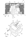
図2(A)は、超音波トランスデューサ30における直交座標系Y−Z面の断面図である。図2(B)は、超音波トランスデューサ30の備える固定部材23の斜視図である。
FIG. 2A is a cross-sectional view of the orthogonal coordinate system YZ plane in the
超音波トランスデューサ30は、上部カバー21、圧電体22、固定部材23、ウェイト24、外部接続端子25、ワッシャ26、バネ状金属端子27A,27B、吸音部材28A,28B、および充填剤29を備える。
The
この超音波トランスデューサ30を送波器として利用する際には、外部接続端子25に駆動信号を印加することで、圧電体22がX−Y面で広がり振動する。すると、上部カバー21の底面にZ軸に沿ったベンディング振動が励起して超音波を送波する。受波器として利用する際には、上部カバー21の底面が超音波を受波して振動することで、圧電体22が広がり振動して外部接続端子25に受波信号が生じる。
When this
上部カバー21はZ軸正方向の端部が閉塞する有底筒状である。ウェイト24は中心軸がZ軸に沿う筒状であり、Z軸正方向の端部が上部カバー21の筒内に挿入および嵌合される。このウェイト24は、固定部材23を保持するための保持部24Aと、ワッシャ26を配置するための凹部24Bとを備える。保持部24Aは、X−Y面でケース中心軸方向に突出する。これらの上部カバー21およびウェイト24は組み合わされて有底筒状のケースを構成する。なお、上部カバー21はケースの底面部に相当する。ワッシャ26は開口を備える平板であり、ウェイト24の凹部24Bに挿入される。
The
上部カバー21は例えばアルミニウムなどの金属材料が使用され、ウェイト24は例えば亜鉛や鉄、ステンレスなど、上部カバー21に用いられた材料よりも比重の高い金属材料が使用されることが好ましい。上部カバー21の作製には、予め高分子ポリエステル塗装された板材の絞り加工や鍛造といった方法を用いることで塗装品質向上やコスト削減が可能となる。また上部カバー21とウェイト24とは溶接、熱圧着、かしめ、接着、嵌合などの方法で接続されるが、例えば接着嵌合の場合にはウェイト24の表面はメッキやサンドブラスト処理、プライマーコーティングを行うことで耐食性や接着性向上を図ってもよい。また図示しないが、ウェイトのZ軸正方向のヘッド部分にRやテーパを設けることで嵌合のしやすさを改善してもよい。なお、ウェイト24の表面に施されるメッキの種類には銅下地ニッケル、または上部カバー21との間で異種金属接触腐食が起こりにくい材料、例えばクロムやスズ系が適している。ウェイト24のZ軸負方向側には組み立て時の搬送用チャッキングや実装後の抜け防止のためにフランジ部を設けても良い。その場合フランジ部は、ウェイト24の開口と同心円状の円形状でも良いし、多角形状としても良い。また、ウェイト24はZ軸方向もしくはX−Y軸方向に2ピース構造等、複数ピースに分割してもよい。ウェイト24はバネ状金属端子27Bを介してグランド電極に接続されるが、その他の接続方法として溶接、熱圧着、かしめ、接着等、種々の方法を用いてもよい。
The
充填剤29は、ウェイト24の筒内部における固定部材23及び吸音部材28AよりもZ軸負方向の空間に充填される。
The
圧電体22はZ軸正方向に沿った分極軸を有し、上部カバー21の内底面に接着剤で接合される。圧電体22の駆動電極(不図示)は、バネ状金属端子27A,27Bを介して外部接続端子25に接続される。
The
図2(B)に詳細構成を示す固定部材23は、上部ベース23A、下部ベース23B、端子保持部23C、係止爪32A,32B、および受け部33A,33Bを備える。下部ベース23Bは一部に欠けのある略円板状である。上部ベース23Aは下部ベース23BよりもX−Y面での外形が小さな略角板状であり、下部ベース23BのZ軸正方向に設けられる。端子保持部23Cは下部ベース23Bおよび上部ベース23AよりもX−Y面での外形が小さい角柱状であり、下部ベース23BのZ軸負方向に設けられる。これら上部ベース23A、下部ベース23B、および端子保持部23CのX−Y面での中心は略一致する。
The fixing
係止爪32A,32Bは下部ベース23BにおけるZ軸正方向の主面の上部ベース23Aとの接続部付近から、先端が上部ベース23AよりもZ軸正方向の位置へ突出するように設け、Z軸正方向の先端に返し部を備える。受け部33A,33Bは、Y軸正方向に延びる三角柱状であり、上部ベース23AのZ軸正方向の主面に設ける。
The locking
この固定部材23はウェイト24の筒内に収容され、下部ベース23BのZ軸正方向の主面が保持部24AのZ軸負方向の主面に接触して、ウェイト24に対して位置決めされる。係止爪32A,32Bは、保持部24AよりもZ軸正方向の位置へ挿入され、返し部が保持部24AのZ軸正方向の主面に接触する。これにより、下部ベース23Bと係止爪32A,32Bとが保持部24Aを狭持する。端子保持部23Cは、ワッシャ26の開口内を通過してZ軸負方向に突出する。
The fixing
外部接続端子25はZ軸正方向の端部が固定部材23の端子保持部23Cに挿入および固定され、Z軸負方向の端部が固定部材23から突出する。吸音部材28AはZ軸正方向の主面が受け部33Aに接触しZ軸負方向の主面が固定部材23の下部ベース23Bに接触して支持される。吸音部材28BはZ軸正方向の主面が圧電体22に接触することがないように離間して設けられ、Z軸負方向の主面が固定部材23の上部ベース23Aに接着される。
The end of the
吸音部材28A,28Bは、ケースの内側空間に設ける事により音波の減衰を進展させる。本願発明における吸音部材とは、音波の吸収率>音波の反射率の関係を満たす構成である。吸音材としては、例えばフェルト、スポンジ等を用いることができる。ただし、バネ状金属端子27Aや圧電体22に吸音部材28A,28Bが接触すると、振動が吸音部材28A,28Bを介して固定部材23に伝搬して、残響特性が著しく悪化する場合もある。このため、固定部材23のバネ状金属端子27Aの下方に相当する位置に部分的な切り欠き(開口)を設けるとともに吸音部材28A,28Bを分割し、吸音部材28Aを開口内に配置している。
The sound absorbing members 28 </ b> A and 28 </ b> B develop sound wave attenuation by being provided in the inner space of the case. The sound-absorbing member in the present invention is a structure that satisfies the relationship of acoustic wave absorption rate> sound wave reflectance. As the sound absorbing material, for example, felt, sponge or the like can be used. However, when the
以上の構成では、固定部材23は圧電体22に対向する反射部として機能する。なお、本発明における反射部の定義は、音波の吸収率<音波の反射率の関係を満たす構成であり、例えばエポキシ樹脂等の樹脂、セラミック、金属等が用いられる。この反射部として機能する固定部材23により、固定部材23と圧電体22との間隔Lに応じて、超音波トランスデューサ30の残響特性が変化することになる。したがって間隔Lを、超音波の1/4波長の奇数倍となる条件、または、超音波の1/4波長以下となる条件を満足するように設定することにより、超音波トランスデューサ30の残響特性を改善することができる。
In the above configuration, the fixing
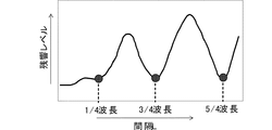
図3は、前記間隔Lと超音波トランスデューサ30の残響レベルとの関係を説明する図である。
ここでは、ケース材:アルミニウム、ケース外径: Φ14mm、圧電体により実質的に振動するケース内径:Φ8mm、反射部:PBT、反射部面積: 8mm2、圧電体径:Φ6mm、駆動条件:48kHz、3.75Vp−pとしている。
FIG. 3 is a diagram for explaining the relationship between the interval L and the reverberation level of the
Here, the case material: aluminum, the case outer diameter: Φ14 mm, the case inner diameter that is substantially vibrated by the piezoelectric body: Φ8 mm, the reflection part: PBT, the reflection part area: 8 mm 2 , the piezoelectric body diameter: Φ6 mm, the drive condition: 48 kHz, 3.75 Vp-p.
この超音波トランスデューサ30の残響レベルは、固定部材23と圧電体22との間隔Lが超音波の半波長分変化する周期で振動し、間隔Lが超音波の1/4波長の奇数倍となる条件で極小化する。また、間隔Lが超音波の1/4波長以下となる条件で、間隔Lが超音波の1/4波長の奇数倍となる条件の場合と同程度の残響レベルになる。
The reverberation level of the
このことから、超音波の1/4波長の奇数倍となる条件、または、超音波の1/4波長以下となる条件を満足するように、超音波トランスデューサ30における固定部材23と圧電体22との間隔Lを設定することにより、超音波トランスデューサ30の残響特性を改善できることがわかる。
From this, the fixing
なお、圧電体22と固定部材23とが接触すると残響特性は低下する恐れがあるので、固定部材23と圧電体22との間隔Lは圧電体22の最大変位距離以上、例えば50um以上、確保することで、圧電体22と固定部材23との接触を防ぐことができ好適である。
In addition, since the reverberation characteristic may be deteriorated when the
次に、本願発明の第2の実施形態に係る超音波トランスデューサ10について説明する。
Next, an
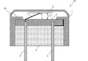
図4は超音波トランスデューサ10の断面図である。
FIG. 4 is a cross-sectional view of the
超音波トランスデューサ10は、ケース1、圧電体2、固定部材3、充填剤4、外部接続端子5、導電性接着剤6、および、内部配線7を備える。
The
この超音波トランスデューサ10を送波器として利用する際には、外部接続端子5に駆動信号を印加することで、圧電体2が水平面で広がり振動し、ケース1の底面に鉛直方向に沿ったベンディング振動が励起して超音波を送波する。受波器として利用する際には、ケース1の底面が超音波を受波して鉛直方向に沿って振動することで、圧電体2が広がり振動して外部接続端子5に受波信号が生じる。
When this
ケース1は、鉛直方向を主軸方向とする有底筒状であり、鉛直上方向の端部が閉塞する。ケース1の筒内部には、固定部材3を保持するための保持部1Aを備える。保持部1Aは、X−Y面でケース中心軸方向に突出する。圧電体2は鉛直方向に沿った分極軸を有し、ケース1の内底面に接着剤(不図示)で接着されている。固定部材3はケース1の筒内部に収容されていて、保持部1Aの鉛直下方向の主面に接触して位置決めされる。充填剤4は、ケース1の筒内部における固定部材3よりも鉛直下方向の空間に充填される。外部接続端子5は鉛直上方向の端部が固定部材3に挿入および固定され、鉛直下方向の端部がケース1の筒内部から突出する。内部配線7は外部接続端子5と圧電体2とを導通させる。導電性接着剤6は、内部配線7と圧電体2とを接続する。
The case 1 has a bottomed cylindrical shape with the vertical direction as the main axis direction, and the end in the vertical direction is closed. A holding portion 1 </ b> A for holding the fixing
以上の構成でも、固定部材3は圧電体2に対向する反射部として機能し、この固定部材3により、固定部材3と圧電体2との間隔L1に応じて、超音波トランスデューサ10の残響特性が変化する。したがって、間隔L1を、超音波の1/4波長の奇数倍となる条件、または、超音波の1/4波長以下となる条件を満足するように設定することにより、超音波トランスデューサ10の残響特性を改善することができる。また、間隔L1は圧電体2の最大変位距離以上確保することで、圧電体2と固定部材3との接触を防ぐことができる。
Even in the above configuration, the fixing
次に、本発明の第3の実施形態に係る超音波トランスデューサ20を説明する。
Next, an
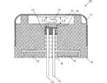
図5は、超音波トランスデューサ20における部分断面図である。
FIG. 5 is a partial cross-sectional view of the
超音波トランスデューサ20は、上部カバー11、圧電体12、固定部材13、ウェイト14、外部接続端子15、ワッシャ16、バネ状金属端子17、吸音部材18、および充填剤19を備える。
The
この超音波トランスデューサ20を送波器として利用する際には、外部接続端子15に駆動信号を印加することで、圧電体12が水平面で広がり振動する。すると、上部カバー11の底面に鉛直上方向に沿ったベンディング振動が励起して超音波を送波する。受波器として利用する際には、上部カバー11の底面が超音波を受波して振動することで、圧電体12が広がり振動して外部接続端子15に受波信号が生じる。
When the
上部カバー11は鉛直上方向の端部が閉塞する有底筒状である。ウェイト14は中心軸が鉛直軸に沿う筒状であって鉛直下方向の開口部の円周に凹部が設けられていて、鉛直上方向の端部が上部カバー11の筒内に挿入および嵌合される。これらの上部カバー11およびウェイト14は組み合わされて有底筒状のケースを構成する。なお、上部カバー11はケースの底面部に相当する。
The
圧電体12は鉛直方向に沿った分極軸を有し、上部カバー11の内底面に接着剤で接合される。圧電体12の駆動電極(不図示)は、バネ状金属端子17を介して外部接続端子15に電気的に接続される。固定部材13はウェイト14の筒内に収容され、バネ状金属端子17および外部接続端子15を固定する。外部接続端子15は鉛直上方向の端部が固定部材13に挿入され、鉛直下方向の端部が固定部材13から突出する。吸音部材18は固定部材13の鉛直上方向に配置される。ワッシャ16は外部接続端子15が挿入される開口を備える平板であり、ウェイト14の鉛直下方向側の凹部に挿入される。充填剤19はウェイト14の筒内部の固定部材13よりも鉛直下方向側の空間に充填される。
The
この構成では、固定部材13とウェイト14の一部が圧電体12に対向する反射部として機能する。そのため、固定部材13と圧電体12との間隔L2およびウェイト14と圧電体12との間隔L3とを適切に設定することにより、超音波トランスデューサ20の残響特性を改善できる。例えば間隔L2を超音波の1/4波長の奇数倍となる条件を満足するように設定し、間隔L3を超音波の1/4波長以下となる条件を満足するように設定すると好適である。また、間隔L2およびL3は圧電体12の最大変位距離以上確保することで、圧電体12と固定部材13および吸音部材18との接触を防ぐことができる。
In this configuration, a part of the fixing
このように、間隔L2およびL3を、音波の1/4波長の略奇数倍、または、音波の1/4波長以下とすることにより残響特性を改善できる。さらには、上部カバー11と固定部材13との間に吸音部材18を設けることで、残響特性をより改善することができる。
In this way, the reverberation characteristics can be improved by setting the intervals L2 and L3 to be approximately odd multiples of 1/4 wavelength of the sound wave, or less than 1/4 wavelength of the sound wave. Furthermore, by providing the
10,20,30…超音波トランスデューサ
1…ケース
2,12,22…圧電体
3,13,23…固定部材
4,19,29…充填剤
5,15,25…外部接続端子
6…導電性接着剤
7…内部配線
11,21…上部カバー
14,24…ウェイト
16,26…ワッシャ
17,27A,27B…バネ状金属端子
18,28A,28B…吸音部材
DESCRIPTION OF
Claims (3)
前記ケースの内底面部に形成される圧電体と、
前記ケースの内底面部から離間して配置され、前記圧電体に対向する反射部と、
を備え、
前記圧電体と前記反射部との間隔が、前記圧電体の最大変位距離よりも大きく、且つ、音波の1/4波長の略奇数倍または1/4波長以下である超音波トランスデューサ。 A bottomed cylindrical case with a closed end in the main axis direction;
A piezoelectric body formed on the inner bottom surface of the case;
A reflective portion that is disposed apart from the inner bottom surface portion of the case and faces the piezoelectric body;
With
An ultrasonic transducer in which an interval between the piezoelectric body and the reflecting portion is larger than a maximum displacement distance of the piezoelectric body and is approximately an odd multiple of 1/4 wavelength of a sound wave or 1/4 wavelength or less.
Priority Applications (5)
| Application Number | Priority Date | Filing Date | Title |
|---|---|---|---|
| JP2009228462A JP4947115B2 (en) | 2009-09-30 | 2009-09-30 | Ultrasonic transducer |
| KR1020100088216A KR101161089B1 (en) | 2009-09-30 | 2010-09-09 | Ultrasonic transducer |
| EP10275095.7A EP2306447B1 (en) | 2009-09-30 | 2010-09-14 | Ultrasonic Transducer |
| US12/889,457 US8354775B2 (en) | 2009-09-30 | 2010-09-24 | Ultrasonic transducer |
| CN2010102970574A CN102034468B (en) | 2009-09-30 | 2010-09-28 | ultrasonic transducer |
Applications Claiming Priority (1)
| Application Number | Priority Date | Filing Date | Title |
|---|---|---|---|
| JP2009228462A JP4947115B2 (en) | 2009-09-30 | 2009-09-30 | Ultrasonic transducer |
Publications (2)
| Publication Number | Publication Date |
|---|---|
| JP2011077918A JP2011077918A (en) | 2011-04-14 |
| JP4947115B2 true JP4947115B2 (en) | 2012-06-06 |
Family
ID=43500277
Family Applications (1)
| Application Number | Title | Priority Date | Filing Date |
|---|---|---|---|
| JP2009228462A Active JP4947115B2 (en) | 2009-09-30 | 2009-09-30 | Ultrasonic transducer |
Country Status (5)
| Country | Link |
|---|---|
| US (1) | US8354775B2 (en) |
| EP (1) | EP2306447B1 (en) |
| JP (1) | JP4947115B2 (en) |
| KR (1) | KR101161089B1 (en) |
| CN (1) | CN102034468B (en) |
Families Citing this family (12)
| Publication number | Priority date | Publication date | Assignee | Title |
|---|---|---|---|---|
| JP4947115B2 (en) * | 2009-09-30 | 2012-06-06 | 株式会社村田製作所 | Ultrasonic transducer |
| JP5099175B2 (en) * | 2010-05-28 | 2012-12-12 | 株式会社村田製作所 | Ultrasonic sensor |
| JP5990930B2 (en) | 2012-02-24 | 2016-09-14 | セイコーエプソン株式会社 | Ultrasonic transducer element chip and probe, electronic device and ultrasonic diagnostic apparatus |
| JP6102075B2 (en) | 2012-03-30 | 2017-03-29 | セイコーエプソン株式会社 | Ultrasonic transducer element chip and probe, electronic device and ultrasonic diagnostic apparatus |
| JP5900107B2 (en) | 2012-03-30 | 2016-04-06 | セイコーエプソン株式会社 | Ultrasonic transducer element chip and probe, electronic device and ultrasonic diagnostic apparatus |
| US9338556B2 (en) * | 2012-10-15 | 2016-05-10 | Nec Corporation | Electroacoustic transducer, manufacturing method thereof, and electronic device utilizing same |
| JP6175780B2 (en) | 2013-01-28 | 2017-08-09 | セイコーエプソン株式会社 | Ultrasonic device, ultrasonic probe, electronic device and ultrasonic imaging apparatus |
| CN108671426B (en) * | 2018-07-17 | 2023-12-05 | 重庆医科大学 | Ultrasonic transducer |
| DE102018213293A1 (en) * | 2018-08-08 | 2020-02-13 | Robert Bosch Gmbh | Ultrasonic transducer with resonance room |
| DE102019115032A1 (en) * | 2019-06-04 | 2020-12-10 | Tdk Electronics Ag | Ultrasonic transducer |
| JP7670480B2 (en) | 2020-12-25 | 2025-04-30 | Tdk株式会社 | Ultrasonic Transducers |
| WO2022225030A1 (en) * | 2021-04-22 | 2022-10-27 | 株式会社メムス・コア | Ultrasonic receiver and ultrasonic observation device |
Family Cites Families (26)
| Publication number | Priority date | Publication date | Assignee | Title |
|---|---|---|---|---|
| JPS5339771A (en) * | 1976-09-24 | 1978-04-11 | Nec Corp | Water pressure resisting transmitter and receelver |
| DE3478357D1 (en) * | 1983-03-17 | 1989-06-29 | Matsushita Electric Industrial Co Ltd | Ultrasonic transducers having improved acoustic impedance matching layers |
| JPH0749914Y2 (en) * | 1986-01-29 | 1995-11-13 | 株式会社村田製作所 | Ultrasonic transducer |
| JPH02116300A (en) * | 1988-10-26 | 1990-04-27 | Matsushita Electric Ind Co Ltd | ultrasonic ceramic microphone |
| JP2988707B2 (en) | 1990-09-21 | 1999-12-13 | 松下電工株式会社 | Drip-proof ultrasonic microphone |
| US5195373A (en) * | 1991-04-17 | 1993-03-23 | Southwest Research Institute | Ultrasonic transducer for extreme temperature environments |
| US5303210A (en) * | 1992-10-29 | 1994-04-12 | The Charles Stark Draper Laboratory, Inc. | Integrated resonant cavity acoustic transducer |
| JP3242183B2 (en) | 1993-02-23 | 2001-12-25 | 松下電工株式会社 | Drip-proof ultrasonic microphone |
| JP3638153B2 (en) * | 1993-08-13 | 2005-04-13 | 松下電工株式会社 | Drip-proof ultrasonic microphone |
| JPH07322394A (en) * | 1994-03-31 | 1995-12-08 | Terumo Corp | Ultrasonic probe |
| HK1050102A1 (en) * | 2000-01-04 | 2003-06-06 | American Technology Corporation | Piezoelectric film sonic emitter |
| US6443900B2 (en) * | 2000-03-15 | 2002-09-03 | Olympus Optical Co., Ltd. | Ultrasonic wave transducer system and ultrasonic wave transducer |
| DE112004001315T5 (en) * | 2003-07-16 | 2006-05-11 | Murata Mfg. Co., Ltd., Nagaokakyo | Ultrasonic transmitting and receiving device |
| CN2774649Y (en) * | 2005-03-23 | 2006-04-26 | 深圳职业技术学院 | Supersonic liquid treatment energy conversion device |
| JP4682927B2 (en) * | 2005-08-03 | 2011-05-11 | セイコーエプソン株式会社 | Electrostatic ultrasonic transducer, ultrasonic speaker, audio signal reproduction method, ultrasonic transducer electrode manufacturing method, ultrasonic transducer manufacturing method, superdirective acoustic system, and display device |
| EP1924122B1 (en) * | 2005-09-09 | 2014-09-24 | Murata Manufacturing Co., Ltd. | Ultrasonic sensor |
| CN101371616B (en) * | 2006-02-14 | 2012-06-13 | 株式会社村田制作所 | Ultrasonic sensor |
| KR101239306B1 (en) * | 2006-02-14 | 2013-03-05 | 가부시키가이샤 무라타 세이사쿠쇼 | Ultrasonic sensor and fabrication method thereof |
| JP4900022B2 (en) * | 2006-04-28 | 2012-03-21 | 株式会社村田製作所 | Ultrasonic sensor |
| KR101064922B1 (en) * | 2006-10-20 | 2011-09-16 | 가부시키가이샤 무라타 세이사쿠쇼 | Ultrasonic sensors |
| JP4888492B2 (en) * | 2006-11-27 | 2012-02-29 | 株式会社村田製作所 | Ultrasonic transducer |
| CN201263707Y (en) * | 2008-07-18 | 2009-07-01 | 华外医疗器械(上海)有限公司 | Medical ultrasound amplifying device |
| US8085621B2 (en) * | 2008-07-24 | 2011-12-27 | Massa Products Corporation | Ultrasonic transducer with improved method of beam angle control |
| JP4947115B2 (en) * | 2009-09-30 | 2012-06-06 | 株式会社村田製作所 | Ultrasonic transducer |
| JP5330180B2 (en) * | 2009-10-02 | 2013-10-30 | オリンパス株式会社 | Endoscope device |
| US7954387B1 (en) * | 2010-08-18 | 2011-06-07 | General Electric Company | Ultrasonic transducer device |
-
2009
- 2009-09-30 JP JP2009228462A patent/JP4947115B2/en active Active
-
2010
- 2010-09-09 KR KR1020100088216A patent/KR101161089B1/en active Active
- 2010-09-14 EP EP10275095.7A patent/EP2306447B1/en active Active
- 2010-09-24 US US12/889,457 patent/US8354775B2/en active Active
- 2010-09-28 CN CN2010102970574A patent/CN102034468B/en active Active
Also Published As
| Publication number | Publication date |
|---|---|
| JP2011077918A (en) | 2011-04-14 |
| CN102034468B (en) | 2012-10-31 |
| CN102034468A (en) | 2011-04-27 |
| EP2306447A2 (en) | 2011-04-06 |
| KR20110035883A (en) | 2011-04-06 |
| US20110074246A1 (en) | 2011-03-31 |
| US8354775B2 (en) | 2013-01-15 |
| EP2306447B1 (en) | 2020-04-29 |
| EP2306447A3 (en) | 2016-12-14 |
| KR101161089B1 (en) | 2012-06-29 |
Similar Documents
| Publication | Publication Date | Title |
|---|---|---|
| JP4947115B2 (en) | Ultrasonic transducer | |
| CN102353951B (en) | Ultrasonic Sensor | |
| JP5522311B2 (en) | Ultrasonic sensor and manufacturing method thereof | |
| US5446332A (en) | Ultrasonic transducer | |
| US7692367B2 (en) | Ultrasonic transducer | |
| KR101528890B1 (en) | Ultrasonic sensor | |
| JPWO2007094184A1 (en) | Ultrasonic sensor and manufacturing method thereof | |
| US11971479B2 (en) | Ultrasonic sensor | |
| WO2013051525A1 (en) | Ultrasonic sensor | |
| US20060232165A1 (en) | Ultrasonic transmitter-receiver | |
| JP2002262383A (en) | Ultrasonic wave vibrator | |
| US8884495B2 (en) | Piezoelectric sensor | |
| JP5414427B2 (en) | Ultrasonic transceiver | |
| JP5105851B2 (en) | Ultrasonic probe | |
| JP5304578B2 (en) | Ultrasonic transducer | |
| CN102768355B (en) | Ultrasonic sensor | |
| JP5423295B2 (en) | Ultrasonic transducer | |
| JP2008271439A (en) | Ultrasonic sensor | |
| CN221686641U (en) | Ultrasonic radar and vehicle | |
| JP2003302387A (en) | Element container, sensor, and manufacturing method thereof | |
| JP2018129757A (en) | Ultrasonic transducer and ultrasonic sensor |
Legal Events
| Date | Code | Title | Description |
|---|---|---|---|
| A621 | Written request for application examination |
Free format text: JAPANESE INTERMEDIATE CODE: A621 Effective date: 20110915 |
|
| A977 | Report on retrieval |
Free format text: JAPANESE INTERMEDIATE CODE: A971007 Effective date: 20111221 |
|
| TRDD | Decision of grant or rejection written | ||
| A01 | Written decision to grant a patent or to grant a registration (utility model) |
Free format text: JAPANESE INTERMEDIATE CODE: A01 Effective date: 20120207 |
|
| A01 | Written decision to grant a patent or to grant a registration (utility model) |
Free format text: JAPANESE INTERMEDIATE CODE: A01 |
|
| A61 | First payment of annual fees (during grant procedure) |
Free format text: JAPANESE INTERMEDIATE CODE: A61 Effective date: 20120220 |
|
| FPAY | Renewal fee payment (event date is renewal date of database) |
Free format text: PAYMENT UNTIL: 20150316 Year of fee payment: 3 |
|
| R150 | Certificate of patent or registration of utility model |
Ref document number: 4947115 Country of ref document: JP Free format text: JAPANESE INTERMEDIATE CODE: R150 Free format text: JAPANESE INTERMEDIATE CODE: R150 |