JP4946552B2 - External electrode type rare gas fluorescent lamp - Google Patents

External electrode type rare gas fluorescent lamp Download PDF

Info

Publication number
JP4946552B2
JP4946552B2 JP2007070008A JP2007070008A JP4946552B2 JP 4946552 B2 JP4946552 B2 JP 4946552B2 JP 2007070008 A JP2007070008 A JP 2007070008A JP 2007070008 A JP2007070008 A JP 2007070008A JP 4946552 B2 JP4946552 B2 JP 4946552B2
Authority
JP
Japan
Prior art keywords
arc tube
external electrode
power supply
rare gas
fluorescent lamp
Prior art date
Legal status (The legal status is an assumption and is not a legal conclusion. Google has not performed a legal analysis and makes no representation as to the accuracy of the status listed.)
Expired - Fee Related
Application number
JP2007070008A
Other languages
Japanese (ja)
Other versions
JP2008234887A (en
Inventor
幸治 田川
茂義 松本
正樹 井上
充夫 船越
Current Assignee (The listed assignees may be inaccurate. Google has not performed a legal analysis and makes no representation or warranty as to the accuracy of the list.)
Ushio Denki KK
Original Assignee
Ushio Denki KK
Priority date (The priority date is an assumption and is not a legal conclusion. Google has not performed a legal analysis and makes no representation as to the accuracy of the date listed.)
Filing date
Publication date
Application filed by Ushio Denki KK filed Critical Ushio Denki KK
Priority to JP2007070008A priority Critical patent/JP4946552B2/en
Publication of JP2008234887A publication Critical patent/JP2008234887A/en
Application granted granted Critical
Publication of JP4946552B2 publication Critical patent/JP4946552B2/en
Expired - Fee Related legal-status Critical Current
Anticipated expiration legal-status Critical

Links

Images

Landscapes

  • Vessels And Coating Films For Discharge Lamps (AREA)

Description

本発明は、液晶や広告・看板のバックライト用の希ガス蛍光ランプに関し、特に発光管の外周面に電極を設ける外部電極型希ガス蛍光ランプに関する。   The present invention relates to a rare gas fluorescent lamp for backlights of liquid crystals and advertisements / signboards, and more particularly to an external electrode type rare gas fluorescent lamp in which an electrode is provided on the outer peripheral surface of an arc tube.

原稿読み取り用光源として、特許文献1に記載される外部電極型希ガス蛍光ランプがあった。原稿読み取り用光源としての外部電極型希ガス蛍光ランプは、図11を用いて後述するように、発光管の内部に希ガスと蛍光体が封入され、発光管の外面に一対の外部電極が管軸方向に沿って配置されるものである。さらに、原稿読み取り用光源としては、外部電極の全体を覆うように熱収縮チューブが設けられていた。外部電極型希ガス蛍光ランプは、ランプ点灯中、外部電極間で放電が発生することで希ガスが励起され、希ガスの励起光により蛍光体が励起されるものである。この原稿読み取り用光源としての外部電極型希ガス蛍光ランプをバックライト用光源として用いると、外部電極を覆う熱収縮チューブが放電により加熱されて着色する問題が起き、バックライト用光源として照度低下という問題があった。これは、原稿読み取り用光源が1000時間のランプ点灯を要求されるのに対し、バックライト用光源は数万時間のランプ点灯という長時間の使用を要求されるため、熱収縮チューブの着色による照度低下という問題が起きるようになった。   As an original reading light source, there was an external electrode type rare gas fluorescent lamp described in Patent Document 1. As will be described later with reference to FIG. 11, an external electrode type rare gas fluorescent lamp as a light source for reading a document has a rare gas and a phosphor enclosed in an arc tube, and a pair of external electrodes on the outer surface of the arc tube. It is arranged along the axial direction. Further, as a document reading light source, a heat shrinkable tube is provided so as to cover the entire external electrode. In the external electrode type rare gas fluorescent lamp, a rare gas is excited by the occurrence of discharge between the external electrodes during lamp operation, and the phosphor is excited by the excitation light of the rare gas. When this external electrode type rare gas fluorescent lamp as a document reading light source is used as a backlight light source, there is a problem in that the heat shrinkable tube covering the external electrode is heated and colored by discharge. There was a problem. This is because the original reading light source is required to turn on the lamp for 1000 hours, whereas the backlight light source is required to use the lamp for tens of thousands of hours for a long time. The problem of decline began to occur.

このため、図11に示すような外部電極型希ガス蛍光ランプ9が考案された。図11を用いて熱収縮チューブの着色による照度低下を防止した外部電極型希ガス蛍光ランプを説明する。図11(a)は従来の外部電極型希ガス蛍光ランプ9の斜視図であり、(b)は(a)の従来の外部電極型希ガス蛍光ランプ9の管軸方向に対して垂直方向の断面図((a)のG−G断面図)である。図11(c)は、図11(a)の従来の外部電極型希ガス蛍光ランプ9の管軸方向に対して垂直方向の断面図((a)のH−H断面図)である。   For this reason, an external electrode type rare gas fluorescent lamp 9 as shown in FIG. 11 has been devised. An external electrode type rare gas fluorescent lamp that prevents a decrease in illuminance due to coloring of the heat shrinkable tube will be described with reference to FIG. FIG. 11A is a perspective view of a conventional external electrode type rare gas fluorescent lamp 9, and FIG. 11B is a view perpendicular to the tube axis direction of the conventional external electrode type rare gas fluorescent lamp 9 of FIG. It is sectional drawing (GG sectional drawing of (a)). FIG. 11C is a cross-sectional view (HH cross-sectional view of FIG. 11A) perpendicular to the tube axis direction of the conventional external electrode type rare gas fluorescent lamp 9 of FIG.

図11に示す従来の外部電極型希ガス蛍光ランプ9は、管状の発光管91と,蛍光体92と,外部電極93と,給電端子95と,熱収縮チューブ96とからなる。
図11(b)に示すように、管状の発光管91の内周面には蛍光体92が塗布される。発光管91の内部には発光ガスとしてキセノンガスなどの希ガスが封入され、発光管91の管軸方向の両端は封止される。
一対の外部電極93は、発光管91の外周面の長手方向に沿って互いに離間するように配置される。発光管91の外周面に配置された外部電極93は、その長手方向の端部に給電端子95が導電性接着剤を用いて電気的に接続される(特許文献1)。
外部電極93と給電端子95との接続を維持するためには、導電性接着剤だけでは不十分である。このため、発光管91の管軸方向の端部において、輪状の熱収縮チューブ96は、外部電極93と給電端子95とが接する面における給電端子95の外方を覆うと共に発光管91の外周面を周方向に一周を覆う。これにより、外部電極93と給電端子95との接続性を向上させることができる。
外部電極93の長手方向の端部に配置される給電端子95には図示しない電源が接続される。
上記のような従来の外部電極型希ガス蛍光ランプ9は、図示しない電源から電力供給され、外部電極93間の電位差により、発光ガスであるキセノンガスにより真空紫外線が放射され、真空紫外光により、蛍光体92が励起される。外部電極93間にある発光管91は誘電体として機能する。
A conventional external electrode type rare gas fluorescent lamp 9 shown in FIG. 11 includes a tubular arc tube 91, a phosphor 92, an external electrode 93, a power supply terminal 95, and a heat shrinkable tube 96.
As shown in FIG. 11 (b), a phosphor 92 is applied to the inner peripheral surface of the tubular arc tube 91. The arc tube 91 is filled with a rare gas such as xenon gas as the luminescent gas, and both ends of the arc tube 91 in the tube axis direction are sealed.
The pair of external electrodes 93 are arranged so as to be separated from each other along the longitudinal direction of the outer peripheral surface of the arc tube 91. As for the external electrode 93 arrange | positioned at the outer peripheral surface of the arc_tube | light_emitting_tube 91, the electric power feeding terminal 95 is electrically connected to the edge part of the longitudinal direction using a conductive adhesive (patent document 1).
In order to maintain the connection between the external electrode 93 and the power supply terminal 95, the conductive adhesive alone is insufficient. Therefore, at the end of the arc tube 91 in the tube axis direction, the ring-shaped heat shrinkable tube 96 covers the outside of the feed terminal 95 at the surface where the external electrode 93 and the feed terminal 95 are in contact, and the outer peripheral surface of the arc tube 91. Cover the entire circumference in the circumferential direction. Thereby, the connectivity between the external electrode 93 and the power supply terminal 95 can be improved.
A power supply (not shown) is connected to the power supply terminal 95 disposed at the longitudinal end of the external electrode 93.
The conventional external electrode type rare gas fluorescent lamp 9 as described above is supplied with power from a power source (not shown), and due to the potential difference between the external electrodes 93, vacuum ultraviolet rays are emitted by the xenon gas, which is a luminescent gas, The phosphor 92 is excited. The arc tube 91 between the external electrodes 93 functions as a dielectric.

特開平03−269950号公報Japanese Patent Laid-Open No. 03-269950

従来の外部電極型希ガス蛍光ランプ9を液晶のバックライトとして室内で使用する場合、寒冷地のような環境で室内を暖房すると、寒暖の差によって室内に配置された外部電極型希ガス蛍光ランプ9の表面で結露することがあった。この結露によって発生した水滴が熱収縮チューブ96の界面97に集まり、熱収縮チューブ96の界面97に連続的に溜まることがある。熱収縮チューブ96は外部電極93と給電端子95を覆うと共に発光管91の外周面を周方向に一周を覆うので、一対の外部電極93間を結ぶように、熱収縮チューブ96の界面97に連続的に水滴が溜まることになる。このため、ランプ9点灯時の外部電極93への給電によって、外部電極93間を連続的に結ぶ水滴に電気が流れる沿面放電が発生し、ランプ9不点灯になる問題があった。また、熱収縮チューブ96には、有機性の材料からなる場合、沿面放電によって炭化され、ときには発火する問題があった。このような外部電極型希ガス蛍光ランプ9の問題は室内に限られず、屋外での雨にさらされる用途のように外部電極型希ガス蛍光ランプ9の発光管91の外周面に水分が付着する環境で起こるものである。   When the conventional external electrode type rare gas fluorescent lamp 9 is used indoors as a liquid crystal backlight, when the room is heated in an environment such as a cold region, the external electrode type rare gas fluorescent lamp disposed in the room due to the difference in temperature and temperature. Condensation sometimes occurred on the surface of 9. Water droplets generated by this condensation may collect at the interface 97 of the heat-shrinkable tube 96 and continuously accumulate at the interface 97 of the heat-shrinkable tube 96. Since the heat shrinkable tube 96 covers the external electrode 93 and the power supply terminal 95 and covers the outer peripheral surface of the arc tube 91 in the circumferential direction, it continues to the interface 97 of the heat shrinkable tube 96 so as to connect the pair of external electrodes 93. Water drops will accumulate. For this reason, there is a problem that creeping discharge in which electricity flows through water droplets continuously connecting the external electrodes 93 due to power feeding to the external electrodes 93 when the lamps 9 are lit, and the lamps 9 are not lit. Further, when the heat shrinkable tube 96 is made of an organic material, it has a problem that it is carbonized by creeping discharge and sometimes ignites. Such problems of the external electrode type rare gas fluorescent lamp 9 are not limited to indoors, but moisture adheres to the outer peripheral surface of the arc tube 91 of the external electrode type rare gas fluorescent lamp 9 as in the case where it is exposed to rain outdoors. What happens in the environment.

そこで、本発明の目的は、外部電極と給電端子の接続性を向上させると共に沿面放電を防止した外部電極型希ガス蛍光ランプを提供することである。   Accordingly, an object of the present invention is to provide an external electrode type rare gas fluorescent lamp which improves the connectivity between an external electrode and a power supply terminal and prevents creeping discharge.

第1の発明に係る外部電極型希ガス蛍光ランプは、希ガスが封入され内面に蛍光体が設けられた発光管と、前記発光管の外面で発光管の管軸方向に設けられた一方の外部電極と、前記発光管の端部において前記一方の外部電極に電気的に接続された一方の給電端子と、前記一方の外部電極から前記発光管の周方向に離れた位置に前記発光管の管軸方向に設けられた他方の外部電極と、前記発光管の端部において前記他方の外部電極に電気的に接続された他方の給電端子と、からなる外部電極型希ガス蛍光ランプにおいて、前記発光管の端部において前記一方の給電端子と前記一方の外部電極とを覆うように電気絶縁性を有する第1の接着体が設けられるとともに、前記発光管の端部において前記他方の給電端子と前記他方の外部電極とを覆うように電気絶縁性を有する第2の接着体が設けられ、前記第1の接着体と第2の接着体とは、前記発光管の外面上で互いに離間していることを特徴とする。
An external electrode type rare gas fluorescent lamp according to a first aspect of the present invention is an arc tube in which a rare gas is enclosed and a phosphor is provided on the inner surface thereof, and one of the outer tube provided in the tube axis direction of the arc tube on the outer surface of the arc tube. An external electrode; one feeding terminal electrically connected to the one external electrode at an end of the arc tube; and the arc tube at a position away from the one external electrode in the circumferential direction of the arc tube. and the other external electrode provided in the axial direction of the tube, and the other power supply terminal electrically connected to the other external electrode at the end of the arc tube, the external electrode type rare gas fluorescent lamp made of the A first adhesive body having electrical insulation is provided so as to cover the one power supply terminal and the one external electrode at the end of the arc tube, and the other power supply terminal at the end of the arc tube Cover the other external electrode A second adhesive body having electrical insulation is provided, and the first adhesive body and the second adhesive body are separated from each other on the outer surface of the arc tube.

第2の発明に係る外部電極型希ガス蛍光ランプは、希ガスが封入され内面に蛍光体が設けられた発光管と、前記発光管の外面で発光管の管軸方向に設けられた一方の外部電極と、前記発光管の端部において前記一方の外部電極に電気的に接続された一方の給電端子と、前記一方の外部電極から前記発光管の周方向に離れた位置に前記発光管の管軸方向に設けられた他方の外部電極と、前記発光管の端部において前記他方の外部電極に電気的に接続された他方の給電端子と、からなる外部電極型希ガス蛍光ランプにおいて、前記発光管の端部において前記一方の給電端子を覆うように第1の被覆体が設けられとともに、該第1の被覆体と前記発光管との隙間には電気絶縁性を有する第1の接着体が設けられ、前記発光管の端部において前記他方の給電端子を覆うように第2の被覆体が設けられるとともに、該第2の被覆体と前記発光管との隙間には電気絶縁性を有する第2の接着体が設けられ、前記第1の被覆体と第2の被覆体、および、前記第1の接着体と第2の接着体とは、前記発光管の外面上で互いに離間していることを特徴とする。 An external electrode type rare gas fluorescent lamp according to a second aspect of the present invention is an arc tube in which a rare gas is sealed and a phosphor is provided on the inner surface, and one of the outer tube and the outer surface of the arc tube provided in the direction of the tube axis of the arc tube. An external electrode; one feeding terminal electrically connected to the one external electrode at an end of the arc tube; and the arc tube at a position away from the one external electrode in the circumferential direction of the arc tube. and the other external electrode provided in the axial direction of the tube, and the other power supply terminal electrically connected to the other external electrode at the end of the arc tube, the external electrode type rare gas fluorescent lamp made of the A first covering body is provided so as to cover the one feeding terminal at an end of the arc tube, and a first adhesive body having electrical insulation is provided in a gap between the first covering body and the arc tube. It is provided, the other at the end of the arc tube A second cover is provided so as to cover the power supply terminal, and a second adhesive having electrical insulation is provided in a gap between the second cover and the arc tube, and the first cover is provided. The body and the second covering body, and the first adhesive body and the second adhesive body are separated from each other on the outer surface of the arc tube.

本発明に係る外部電極型希ガス蛍光ランプは、前記第1の被覆体が前記発光管の管軸方向の端面を超えて管軸方向に延長され、前記第2の被覆体が前記発光管の管軸方向の端面を超えて管軸方向に延長され、前記延長された前記第1の被覆体と前記第2の被覆体とを接続する接続体が設けられたことを特徴とする第2の発明に記載の外部電極型希ガス蛍光ランプである。   In the external electrode type rare gas fluorescent lamp according to the present invention, the first cover is extended in the tube axis direction beyond the end surface of the tube in the tube axis direction, and the second cover is formed in the tube. A second connection body is provided that extends in the tube axis direction beyond the end surface in the tube axis direction and connects the extended first covering body and the second covering body. It is an external electrode type rare gas fluorescent lamp described in the invention.

本発明に係る外部電極型希ガス蛍光ランプは、前記第1の被覆体又は前記第2の被覆体を押圧し前記発光管の外面で連続しないように押圧体が設けられたことを特徴とする第2の発明に記載の外部電極型希ガス蛍光ランプである。   The external electrode type rare gas fluorescent lamp according to the present invention is characterized in that a pressing body is provided so as to press the first covering body or the second covering body so as not to continue on the outer surface of the arc tube. An external electrode type rare gas fluorescent lamp according to the second invention.

第1の発明に係る外部電極型希ガス蛍光ランプは、希ガスが封入され内面に蛍光体が設けられた発光管と、前記発光管の外面で発光管の管軸方向に設けられた一方の外部電極と、前記一方の外部電極に電気的に接続された一方の給電端子と、前記一方の外部電極から前記発光管の周方向に離れた位置に前記発光管の管軸方向に設けられた他方の外部電極と、前記他方の外部電極に電気的に接続された他方の給電端子と、からなる外部電極型希ガス蛍光ランプにおいて、前記一方の給電端子から前記発光管に渡ると共に前記他方の外部電極と連続しないように電気絶縁性を有する第1の接着体が設けられ、前記他方の給電端子から前記発光管に渡ると共に前記一方の外部電極及び前記第1の接着体と連続しないように電気絶縁性を有する第2の接着体が設けられたことにより、一方の給電端子と発光管とが第1の接着体によって接着されたと共に他方の給電端子と発光管とが第2の接着体によって接着されたので、接着体と発光管との間にある給電端子と外部電極との接続性を向上させることができる。さらに、第1の接着体が他方の外部電極と連続しなかったと共に第2の接着体が一方の外部電極及び第1の接着体と連続しなかったので、発光管の外周面に水分が付着しても、外部電極間を水分が連続的に結ぶことを防止することができる。このため、本発明に係る外部電極型希ガス蛍光ランプは、発光管の外周面に水分が付着する環境において、外部電極間の沿面放電の発生を防止することができる。   An external electrode type rare gas fluorescent lamp according to a first aspect of the present invention includes an arc tube in which a rare gas is sealed and a fluorescent material is provided on the inner surface, and one of the outer surfaces of the arc tube provided in the tube axis direction of the arc tube. An external electrode, one power supply terminal electrically connected to the one external electrode, and a tube axis direction of the arc tube at a position away from the one external electrode in the circumferential direction of the arc tube In an external electrode type rare gas fluorescent lamp comprising the other external electrode and the other power supply terminal electrically connected to the other external electrode, the other power supply terminal crosses the arc tube from the one power supply terminal and the other power supply terminal. A first adhesive body having electrical insulation is provided so as not to be continuous with the external electrode, and extends from the other feeding terminal to the arc tube and is not continuous with the one external electrode and the first adhesive body. Second having electrical insulation By providing the attachment body, one power supply terminal and the arc tube are bonded by the first adhesive body, and the other power supply terminal and the arc tube are bonded by the second adhesive body. The connectivity between the power supply terminal and the external electrode between the arc tube and the arc tube can be improved. Further, since the first adhesive body was not continuous with the other external electrode and the second adhesive body was not continuous with the one external electrode and the first adhesive body, moisture adhered to the outer peripheral surface of the arc tube. Even so, it is possible to prevent moisture from being continuously connected between the external electrodes. For this reason, the external electrode type rare gas fluorescent lamp according to the present invention can prevent the occurrence of creeping discharge between the external electrodes in an environment where moisture adheres to the outer peripheral surface of the arc tube.

第2の発明に係る外部電極型希ガス蛍光ランプは、希ガスが封入され内面に蛍光体が設けられた発光管と、前記発光管の外面で発光管の管軸方向に設けられた一方の外部電極と、前記一方の外部電極に電気的に接続された一方の給電端子と、前記一方の外部電極から前記発光管の周方向に離れた位置に前記発光管の管軸方向に設けられた他方の外部電極と、前記他方の外部電極に電気的に接続された他方の給電端子と、からなる外部電極型希ガス蛍光ランプにおいて、前記一方の給電端子を覆い前記他方の外部電極と連続しないように第1の被覆体が設けられ、前記第1の被覆体と前記発光管との隙間に電気絶縁性を有する第1の接着体が前記他方の外部電極と連続しないように設けられ、前記他方の給電端子を覆い前記一方の外部電極及び前記第1の接着体と連続しないように第2の被覆体が設けられ、前記第2の被覆体と前記発光管との隙間に電気絶縁性を有する第2の接着体が前記一方の外部電極及び前記第1の接着体並びに前記第1の被覆体と連続しないように設けられたことにより、第1の被覆体が一方の給電端子を覆ったと共に第2の被覆体が他方の給電端子を覆ったので、外部電極と給電端子とが接する面の給電端子の外方の機械的強度を向上させることができる。さらに、第1の接着体が第1の被覆体と発光管との隙間に設けられたと共に第2の接着体が第2の被覆体と発光管との隙間に設けられたので、被覆体と発光管との間にある給電端子と外部電極との接続性を向上させることができる。その上、第1の被覆体が他方の外部電極と連続せず、第1の接着体が他方の外部電極と連続せず、第2の被覆体が一方の外部電極及び第1の接着体と連続せず、第2の接着体が一方の外部電極及び第1の接着体並びに第1の被覆体と連続しなかったので、発光管の外周面に水分が付着しても、外部電極間を水分が連続的に結ぶことを防止することができる。このため、本発明に係る外部電極型希ガス蛍光ランプは、発光管の外周面に水分が付着する環境において、外部電極間の沿面放電の発生を防止することができる。   An external electrode type rare gas fluorescent lamp according to a second aspect of the present invention is an arc tube in which a rare gas is sealed and a phosphor is provided on the inner surface, and one of the outer tube and the outer surface of the arc tube provided in the direction of the tube axis of the arc tube. An external electrode, one power supply terminal electrically connected to the one external electrode, and a tube axis direction of the arc tube at a position away from the one external electrode in the circumferential direction of the arc tube In an external electrode type rare gas fluorescent lamp comprising the other external electrode and the other power supply terminal electrically connected to the other external electrode, it covers the one power supply terminal and is not continuous with the other external electrode. A first covering body is provided, and a first adhesive body having electrical insulation is provided in a gap between the first covering body and the arc tube so as not to be continuous with the other external electrode, One of the external electrodes covering the other feeding terminal and The second covering body is provided so as not to be continuous with the first adhesive body, and the second adhesive body having electrical insulation in the gap between the second covering body and the arc tube is the one external electrode. And the first covering body so as not to be continuous with the first covering body, the first covering body covers one feeding terminal and the second covering body serves as the other feeding terminal. Since it is covered, the mechanical strength outside the power supply terminal on the surface where the external electrode and the power supply terminal are in contact can be improved. Further, since the first adhesive body is provided in the gap between the first covering body and the arc tube and the second adhesive body is provided in the gap between the second covering body and the arc tube, The connectivity between the power supply terminal between the arc tube and the external electrode can be improved. In addition, the first cover is not continuous with the other external electrode, the first adhesive is not continuous with the other external electrode, and the second cover is one of the external electrode and the first adhesive. Since the second adhesive body was not continuous with one of the external electrodes, the first adhesive body, and the first covering body, even if moisture adheres to the outer peripheral surface of the arc tube, the gap between the external electrodes is not continuous. It is possible to prevent moisture from being continuously tied. For this reason, the external electrode type rare gas fluorescent lamp according to the present invention can prevent the occurrence of creeping discharge between the external electrodes in an environment where moisture adheres to the outer peripheral surface of the arc tube.

本発明に係る外部電極型希ガス蛍光ランプは、前記第1の被覆体が前記発光管の管軸方向の端面を超えて管軸方向に延長され、前記第2の被覆体が前記発光管の管軸方向の端面を超えて管軸方向に延長され、前記延長された前記第1の被覆体と前記第2の被覆体とを接続する接続体が設けられたことにより、第1の被覆体又は第2の被覆体に負荷が加わっても、接続体によって負荷が分散されるので、接続された外部電極と給電端子の機械的強度を向上させることができる。さらに、接続体と発光管との間に水分が連続的に溜まることを防止することができる。このため、本発明に係る外部電極型希ガス蛍光ランプは、発光管の外周面に水分が付着する環境において、外部電極間の沿面放電の発生を防止することができる。   In the external electrode type rare gas fluorescent lamp according to the present invention, the first cover is extended in the tube axis direction beyond the end surface of the tube in the tube axis direction, and the second cover is formed in the tube. By providing a connection body that extends in the tube axis direction beyond the end surface in the tube axis direction and connects the extended first covering body and the second covering body, the first covering body is provided. Alternatively, even when a load is applied to the second covering body, the load is dispersed by the connecting body, so that the mechanical strength of the connected external electrode and the power feeding terminal can be improved. Furthermore, it is possible to prevent water from being continuously accumulated between the connection body and the arc tube. For this reason, the external electrode type rare gas fluorescent lamp according to the present invention can prevent the occurrence of creeping discharge between the external electrodes in an environment where moisture adheres to the outer peripheral surface of the arc tube.

本発明に係る外部電極型希ガス蛍光ランプは、前記第1の被覆体又は前記第2の被覆体を押圧し前記発光管の外面で連続しないように押圧体が設けられたことにより、押圧体が第1の被覆体又は第2の被覆体を押圧するので、接着体の接着機能による被覆体の給電端子への固定を補完することができ、被覆体の給電端子への固定を強化できる。さらに、押圧体が発光管の外面において連続しないように設けられたことにより、発光管と押圧体との間に水分が連続的に溜まることを防止することができる。このため、本発明に係る外部電極型希ガス蛍光ランプは、発光管の外周面に水分が付着する環境において、外部電極間の沿面放電の発生を防止することができる。   In the external electrode type rare gas fluorescent lamp according to the present invention, the pressing body is provided so as to press the first covering body or the second covering body so as not to continue on the outer surface of the arc tube. Presses the first covering body or the second covering body, so that the fixing of the covering body to the power feeding terminal by the bonding function of the adhesive body can be supplemented, and the fixing of the covering body to the power feeding terminal can be strengthened. Furthermore, by providing the pressing body so as not to be continuous on the outer surface of the arc tube, it is possible to prevent moisture from being continuously accumulated between the arc tube and the pressing body. For this reason, the external electrode type rare gas fluorescent lamp according to the present invention can prevent the occurrence of creeping discharge between the external electrodes in an environment where moisture adheres to the outer peripheral surface of the arc tube.

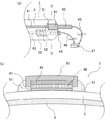
本発明に係る外部電極型希ガス蛍光ランプ1の第1の実施例を図1及び図2を用いて説明する。   A first embodiment of an external electrode type rare gas fluorescent lamp 1 according to the present invention will be described with reference to FIGS.

図1は本発明に係る外部電極型希ガス蛍光ランプ1の説明図である。図1(a)は外部電極型希ガス蛍光ランプ1の斜視図であり、(b)は(a)の外部電極型希ガス蛍光ランプ1の管軸方向に対して垂直方向の断面図((a)のA−A断面図)である。図1(c)は外部電極41,42と給電端子43,44とを接続する接着体51,52を説明するための図であり、外部電極型希ガス蛍光ランプ1の管軸方向に対して垂直方向の断面図((a)のB−B断面図)である。   FIG. 1 is an explanatory view of an external electrode type rare gas fluorescent lamp 1 according to the present invention. FIG. 1A is a perspective view of the external electrode type rare gas fluorescent lamp 1, and FIG. 1B is a cross-sectional view perpendicular to the tube axis direction of the external electrode type rare gas fluorescent lamp 1 of FIG. It is AA sectional drawing of a). FIG. 1 (c) is a diagram for explaining the adhesive bodies 51 and 52 that connect the external electrodes 41 and 42 and the power supply terminals 43 and 44 with respect to the tube axis direction of the external electrode type rare gas fluorescent lamp 1. It is sectional drawing (BB sectional drawing of (a)) of a perpendicular direction.

図1(b)に示すように、管状の発光管2の内周面には、蛍光体3が塗布される。すなわち、蛍光体3は発光管2の内面の軸方向の全長に渡って蛍光体3の層が形成される。発光管2の内部21には発光ガスとして例えばキセノンガスを主成分とする希ガスが封入され、発光管2の両端は封止される。   As shown in FIG. 1B, the phosphor 3 is applied to the inner peripheral surface of the tubular arc tube 2. That is, in the phosphor 3, a layer of the phosphor 3 is formed over the entire axial length of the inner surface of the arc tube 2. The inside 21 of the arc tube 2 is filled with, for example, a rare gas mainly composed of xenon gas as a luminescent gas, and both ends of the arc tube 2 are sealed.

発光管2の外周面には、一対の外部電極41,42が発光管2の外面の長手方向に渡って離間するように配置される。すなわち、一対の外部電極41,42は、発光管2の周方向に離れた位置に発光管の管軸方向に設けられる。
この外部電極41,42は、例えば銀とフリットガラスを混合したペーストを発光管2の外周面の所望の位置に塗布され、400℃以上の大気中で焼成することにより膜状に形成される。
On the outer peripheral surface of the arc tube 2, a pair of external electrodes 41, 42 are disposed so as to be separated in the longitudinal direction of the outer surface of the arc tube 2. That is, the pair of external electrodes 41 and 42 are provided in the tube axis direction of the arc tube at positions separated in the circumferential direction of the arc tube 2.
The external electrodes 41 and 42 are formed in a film shape by, for example, applying a paste in which silver and frit glass are mixed to a desired position on the outer peripheral surface of the arc tube 2 and baking it in the atmosphere of 400 ° C. or higher.

一対の外部電極41,42の長手方向の端部には、それぞれの外部電極41,42を発光管2とで挟むように、板状の給電端子43,44が配置される。一方の外部電極41と、これに接続される一方の給電端子43とは、外部電極41と給電端子43とが接する面の給電端子43の外方(発光管2の径方向の外方)において、第1の接着体51によって覆われる。同様に、他方の外部電極42と、これに接続される他方の給電端子44とは、外部電極42と給電端子44とが接する面の給電端子44の外方(発光管2の径方向の外方)において、第2の接着体52によって覆われる。このように、第1の接着体51及び第2の接着体52によって外部電極41,42と給電端子43,44とが被覆されることにより、外部電極41,42と給電端子43,44とを発光管2の外面へ保持することができ、さらに第1の接着体51及び第2の接着体52の接着性により、外部電極41,42と給電端子43,44との接続性を向上させることができる。
一対の接着体51,52は発光管2の外面も被覆するが、第1の接着体51と第2の接着体52は離間される。すなわち、接着体51,52は発光管2の外面の周方向において連続的に設けられないので、発光管2の外周面に水分が付着する環境において、発光管2の外面の水分が周方向に連続的に結ぶことを防止できる。
Plate-shaped power supply terminals 43 and 44 are arranged at the longitudinal ends of the pair of external electrodes 41 and 42 so that the external electrodes 41 and 42 are sandwiched between the arc tube 2. One external electrode 41 and one power supply terminal 43 connected thereto are outside the power supply terminal 43 on the surface where the external electrode 41 and the power supply terminal 43 are in contact (outward in the radial direction of the arc tube 2). The first adhesive 51 is covered. Similarly, the other external electrode 42 and the other power supply terminal 44 connected to the external electrode 42 are located outside the power supply terminal 44 on the surface where the external electrode 42 and the power supply terminal 44 are in contact (outside of the radial direction of the arc tube 2). 1), it is covered by the second adhesive body 52. As described above, the external electrodes 41 and 42 and the power supply terminals 43 and 44 are covered with the first adhesive body 51 and the second adhesive body 52, so that the external electrodes 41 and 42 and the power supply terminals 43 and 44 are connected. It can be held on the outer surface of the arc tube 2, and the connectivity between the external electrodes 41 and 42 and the power supply terminals 43 and 44 is improved by the adhesiveness of the first adhesive body 51 and the second adhesive body 52. Can do.
The pair of adhesive bodies 51 and 52 also covers the outer surface of the arc tube 2, but the first adhesive body 51 and the second adhesive body 52 are separated from each other. That is, since the adhesive bodies 51 and 52 are not continuously provided in the circumferential direction of the outer surface of the arc tube 2, the moisture on the outer surface of the arc tube 2 is circumferential in the environment where moisture adheres to the outer circumferential surface of the arc tube 2. It is possible to prevent continuous tying.

給電端子43,44は、図1(a)に示すように、発光管2の管軸方向の端部の外面から、管軸方向に突出している。給電端子43,44の突出した部分の内方に給電線45,46が電気的に接続される。給電線45,46の端部にはコネクタ47が接続され、コネクタ47は図示しない電源装置に接続される。   As shown in FIG. 1A, the power supply terminals 43 and 44 protrude in the tube axis direction from the outer surface of the end portion of the arc tube 2 in the tube axis direction. Feed lines 45 and 46 are electrically connected to the inside of the protruding portions of the feed terminals 43 and 44. A connector 47 is connected to the ends of the power supply lines 45 and 46, and the connector 47 is connected to a power supply device (not shown).

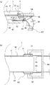
図2は外部電極41と給電端子43とを接続する構造についての説明図であり、図1(c)の一方の外部電極41の拡大図である。図1に示したものと同じものには同一の符号が付されている。   FIG. 2 is an explanatory diagram of a structure for connecting the external electrode 41 and the power supply terminal 43, and is an enlarged view of one external electrode 41 in FIG. The same reference numerals are given to the same components as those shown in FIG.

給電端子43は例えば板状のリン青銅の表面にニッケルメッキを施したものであり、前述のように外部電極41,42の外方(発光管2の径方向に外方)に配置される。外部電極41と給電端子43との間には、これらを電気的に接続する導電性接合体48が設けられる。導電性接合体48は、例えばBi−Snを主成分とする半田48が挙げられ、必要に応じて銀(Ag),銅(Cu)又はアルミニウム(Al)等を添加した半田48を用いることができる。また、導電性接合体48は、半田48に限定されるものでなく、銀(Ag)などの金属をエポキシ樹脂などの樹脂材に混合した導電性接着剤48も使用することができる。   The power supply terminal 43 is, for example, a plate-like phosphor bronze surface plated with nickel, and is disposed outside the external electrodes 41 and 42 (outward in the radial direction of the arc tube 2) as described above. A conductive joined body 48 is provided between the external electrode 41 and the power supply terminal 43 to electrically connect them. Examples of the conductive bonded body 48 include a solder 48 containing Bi-Sn as a main component, and a solder 48 to which silver (Ag), copper (Cu), aluminum (Al) or the like is added as required is used. it can. The conductive bonded body 48 is not limited to the solder 48, and a conductive adhesive 48 in which a metal such as silver (Ag) is mixed with a resin material such as an epoxy resin can also be used.

図2に示すような、発光管2の管軸方向に対して垂直方向の断面において、導電性接合体48によって電気的に接続された外部電極41と給電端子43とは、接着機能を有する接着体51によって被覆される。さらに、接着体51が発光管2の外周面を一部覆って接着することにより、外部電極41と給電端子43とを発光管2の外面における接着性を向上させることができる。   As shown in FIG. 2, in the cross section perpendicular to the tube axis direction of the arc tube 2, the external electrode 41 and the power supply terminal 43 that are electrically connected by the conductive joined body 48 are bonded with an adhesive function. Covered by the body 51. Furthermore, the adhesive 51 covers a part of the outer peripheral surface of the arc tube 2 and adheres, whereby the adhesion between the external electrode 41 and the power supply terminal 43 on the outer surface of the arc tube 2 can be improved.

なお、接着体51,52は、接着機能を有する樹脂として例えばエポキシ樹脂,フェノール樹脂又はシリコーン樹脂等を主成分とする接着性樹脂を用いることができ、またセラミックス系の接着剤としてリン酸系接着剤等を用いることができる。このような樹脂又は接着剤は電気絶縁性を有している。これらを接着体51,52として用いることにより、外部電極41,42と給電端子43,44とが接する面の給電端子43,44の外方における電気絶縁性を向上させることができる。   For the adhesive bodies 51 and 52, for example, an adhesive resin mainly composed of an epoxy resin, a phenol resin, or a silicone resin can be used as a resin having an adhesive function, and a phosphoric acid based adhesive is used as a ceramic adhesive. An agent or the like can be used. Such a resin or adhesive has electrical insulation. By using these as the adhesive bodies 51 and 52, it is possible to improve electrical insulation outside the power supply terminals 43 and 44 on the surface where the external electrodes 41 and 42 and the power supply terminals 43 and 44 are in contact with each other.

上述の外部電極型希ガス蛍光ランプ1は、ランプ1点灯時、図示しない電源装置から給電端子43,44に給電され、これに電気的に接続された一対の離間された外部電極41,42に給電される。給電端子43,44と外部電極41,42とを被覆する接着体51,52は発光管2の外面の周方向において離間されているので、発光管2の外面に結露等による水分が発生していても、一対の外部電極41,42間を水分が連続的に結ぶことはない。すなわち、接着体51,52が発光管2の外面の周方向において連続的に設けられないことにより、発光管2の外面の水分による沿面放電を防止することができる。   In the external electrode type rare gas fluorescent lamp 1 described above, when the lamp 1 is turned on, power is supplied to the power supply terminals 43 and 44 from a power supply device (not shown), and a pair of spaced apart external electrodes 41 and 42 electrically connected thereto are connected. Power is supplied. Since the adhesive bodies 51 and 52 covering the power supply terminals 43 and 44 and the external electrodes 41 and 42 are separated in the circumferential direction of the outer surface of the arc tube 2, moisture due to condensation or the like is generated on the outer surface of the arc tube 2. However, moisture does not continuously connect between the pair of external electrodes 41 and 42. That is, since the adhesive bodies 51 and 52 are not continuously provided in the circumferential direction of the outer surface of the arc tube 2, creeping discharge due to moisture on the outer surface of the arc tube 2 can be prevented.

本発明に係る外部電極型希ガス蛍光ランプ1は、希ガスが封入され内面に蛍光体3が設けられた発光管2と、前記発光管2の外面で発光管2の管軸方向に設けられた一方の外部電極41と、前記一方の外部電極41に電気的に接続された一方の給電端子43と、前記一方の外部電極41から前記発光管2の周方向に離れた位置に前記発光管2の管軸方向に設けられた他方の外部電極42と、前記他方の外部電極42に電気的に接続された他方の給電端子44と、からなる外部電極型希ガス蛍光ランプ1において、前記一方の給電端子43から前記発光管2に渡ると共に前記他方の外部電極42と連続しないように電気絶縁性を有する第1の接着体51が設けられ、前記他方の給電端子44から前記発光管2に渡ると共に前記一方の外部電極41及び前記第1の接着体51と連続しないように電気絶縁性を有する第2の接着体52が設けられたことにより、一方の給電端子43と発光管2とが第1の接着体51によって接着されたと共に他方の給電端子44と発光管2とが第2の接着体52によって接着されたので、接着体51,52と発光管2との間にある給電端子43,44と外部電極41,42との接続性を向上させることができる。さらに、第1の接着体51が他方の外部電極42と連続しなかったと共に第2の接着体52が一方の外部電極41及び第1の接着体51と連続しなかったので、発光管2の外周面に水分が付着しても、外部電極41,42間を水分が連続的に結ぶことを防止することができる。このため、本発明に係る外部電極型希ガス蛍光ランプ1は、発光管2の外周面に水分が付着する環境において、外部電極41,42間の沿面放電の発生を防止することができる。   An external electrode type rare gas fluorescent lamp 1 according to the present invention is provided in a tube axis direction of the arc tube 2 on the outer surface of the arc tube 2 and an arc tube 2 in which a rare gas is sealed and a phosphor 3 is provided on the inner surface. One external electrode 41, one power supply terminal 43 electrically connected to the one external electrode 41, and the arc tube at a position away from the one external electrode 41 in the circumferential direction of the arc tube 2. In the external electrode type rare gas fluorescent lamp 1, which includes the other external electrode 42 provided in the direction of the tube axis 2 and the other power supply terminal 44 electrically connected to the other external electrode 42. A first adhesive body 51 having electrical insulation is provided so as not to be continuous with the other external electrode 42 from the power supply terminal 43 to the arc tube 2, and from the other power supply terminal 44 to the arc tube 2. And the one external electrode 4 In addition, since the second adhesive body 52 having electrical insulation is provided so as not to be continuous with the first adhesive body 51, one power supply terminal 43 and the arc tube 2 are bonded by the first adhesive body 51. Since the other power supply terminal 44 and the arc tube 2 are bonded together by the second adhesive body 52, the power supply terminals 43 and 44 and the external electrode 41 between the adhesive bodies 51 and 52 and the arc tube 2 are connected. Connectivity with 42 can be improved. Furthermore, since the first adhesive body 51 was not continuous with the other external electrode 42 and the second adhesive body 52 was not continuous with the one external electrode 41 and the first adhesive body 51, Even if moisture adheres to the outer peripheral surface, it is possible to prevent moisture from being continuously connected between the external electrodes 41 and 42. Therefore, the external electrode type rare gas fluorescent lamp 1 according to the present invention can prevent the occurrence of creeping discharge between the external electrodes 41 and 42 in an environment where moisture adheres to the outer peripheral surface of the arc tube 2.

本発明に係る外部電極型希ガス蛍光ランプ1の第1の実施例の別の実施例を図3を用いて説明する。   Another embodiment of the first embodiment of the external electrode type rare gas fluorescent lamp 1 according to the present invention will be described with reference to FIG.

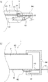
図3は本発明に係る外部電極型希ガス蛍光ランプ1の説明図である。図3(a)は外部電極型希ガス蛍光ランプ1の給電端子43,44が配置された一方の端部の斜視図である。図3(b)は(a)の外部電極型希ガス蛍光ランプ1の管軸方向に対して垂直方向の断面図((a)のC−C断面図)であり、一方の外部電極41の周辺の拡大図である。図3は、図1に示したものと同じものには同一の符号が付されている。
図3は、給電端子43が発光管2の周方向において外部電極41に対して幅広であり、発光管2と給電端子43との間に隙間が形成された点で図2と相違する。図3の説明として、図2との相違点について述べる。
FIG. 3 is an explanatory view of the external electrode type rare gas fluorescent lamp 1 according to the present invention. FIG. 3A is a perspective view of one end of the external electrode type rare gas fluorescent lamp 1 where the power supply terminals 43 and 44 are disposed. 3B is a cross-sectional view perpendicular to the tube axis direction of the external electrode type rare gas fluorescent lamp 1 in FIG. 3A (a cross-sectional view taken along the line CC in FIG. 3A). FIG. 3, the same components as those shown in FIG. 1 are denoted by the same reference numerals.
FIG. 3 is different from FIG. 2 in that the feeding terminal 43 is wider than the external electrode 41 in the circumferential direction of the arc tube 2 and a gap is formed between the arc tube 2 and the feeding terminal 43. As an explanation of FIG. 3, differences from FIG. 2 will be described.

発光管2の周方向において、図3(b)に示すように、外部電極41より幅広の給電端子43は、外部電極41の外方(発光管2の径方向の外方)に配置される。このため、給電端子43と発光管2との間に隙間が形成される。給電端子43の外方(発光管2の径方向の外方)において、給電端子43は第1の接着体51によって覆われる。このとき、図3(b)に示すように、給電端子43と発光管2との間に形成された隙間が残ったまま、第1の接着体51が、給電端子43から発光管2に渡って設けられることがある。給電端子43と発光管2との間に隙間が残ったままであっても、給電端子43から発光管2に渡って設けることにより、給電端子43を発光管2の外方に保持することができ、給電端子43と発光管2に挟まれた外部電極41も発光管2の外面に保持することができる。
本実施例に係る外部電極型希ガス蛍光ランプ1は、給電端子43と発光管2と第1の接着体51の間に隙間が形成されても、第1の実施例で説明した外部電極型希ガス蛍光ランプ1と同様の効果を得られる。
In the circumferential direction of the arc tube 2, as shown in FIG. 3B, the power supply terminal 43 wider than the external electrode 41 is disposed outside the external electrode 41 (outside in the radial direction of the arc tube 2). . For this reason, a gap is formed between the power supply terminal 43 and the arc tube 2. Outside the power supply terminal 43 (outward in the radial direction of the arc tube 2), the power supply terminal 43 is covered with the first adhesive 51. At this time, as shown in FIG. 3B, the first adhesive 51 crosses from the power supply terminal 43 to the arc tube 2 while the gap formed between the power supply terminal 43 and the arc tube 2 remains. May be provided. Even if a gap remains between the power supply terminal 43 and the arc tube 2, the power supply terminal 43 can be held outside the arc tube 2 by being provided from the power supply terminal 43 to the arc tube 2. The external electrode 41 sandwiched between the power supply terminal 43 and the arc tube 2 can also be held on the outer surface of the arc tube 2.
The external electrode type rare gas fluorescent lamp 1 according to the present embodiment has the external electrode type described in the first embodiment even if a gap is formed between the power supply terminal 43, the arc tube 2, and the first adhesive body 51. The same effect as the rare gas fluorescent lamp 1 can be obtained.

本発明に係る外部電極型希ガス蛍光ランプ1の第1の実施例の別の実施例を図4を用いて説明する。   Another embodiment of the first embodiment of the external electrode type rare gas fluorescent lamp 1 according to the present invention will be described with reference to FIG.

図4は本発明に係る外部電極型希ガス蛍光ランプ1の説明図であり、外部電極型希ガス蛍光ランプ1の斜視図である。図4は図1に示したものと同じものには同一の符号が付されている。
図4は、給電端子43,44を配置した位置が図1と相違する。図4の説明として、図1との相違点について述べる。
FIG. 4 is an explanatory view of the external electrode type rare gas fluorescent lamp 1 according to the present invention, and is a perspective view of the external electrode type rare gas fluorescent lamp 1. 4, the same components as those shown in FIG. 1 are denoted by the same reference numerals.
4 is different from FIG. 1 in the positions where the power supply terminals 43 and 44 are arranged. As an explanation of FIG. 4, differences from FIG. 1 will be described.

一対の外部電極41,42の内、一方の外部電極41における長手方向の一方の端部に一方の給電端子43が配置され、他方の外部電極42における長手方向の他方の端部に他方の給電端子44が配置される。すなわち、発光管2の長手方向の一方の端部に一方の給電端子43が配置され、他方の端部に他方の給電端子44が配置されるため、一対の給電端子43,44は発光管の長手方向において離間される。
一方の外部電極41と、これに接続される一方の給電端子43とは、一方の外部電極41と一方の給電端子43とが接する面の一方の給電端子43の外方(発光管2の径方向の外方)において、第1の接着体51によって覆われる。同様に、他方の外部電極42と、これに接続される他方の給電端子44とは、他方の外部電極42と他方の給電端子44とが接する面の他方の給電端子44の外方(発光管2の径方向の外方)において、第2の接着体52によって覆われる。このように、第1の接着体51及び第2の接着体52によって外部電極41,42と給電端子43,44とが被覆されることにより、外部電極41,42と給電端子43,44とを発光管2の外面へ保持することができ、さらに第1の接着体51及び第2の接着体52の接着性により、外部電極41,42と給電端子43,44との接続性を向上させることができる。
一対の接着体51,52は発光管2の外面も被覆するが、第1の接着体51と第2の接着体52は発光管2の長手方向において離間される。さらに、一方の外部電極41と一方の給電端子43とが接する面の一方の給電端子43の外方(発光管2の径方向の外方)に設けた第1の接着体51は、他方の外部電極42に連続的に設けられない。また、他方の外部電極42と他方の給電端子44とが接する面の他方の給電端子44の外方(発光管2の径方向の外方)に設けた第2の接着体52は、一方の外部電極41に連続的に設けられない。すなわち、接着体51,52は、一対の外部電極41,42間に連続的に設けられないので、発光管2の外周面に水分が付着する環境において、発光管2の外面の水分が周方向に連続的に結ぶことを防止できる。
Of the pair of external electrodes 41, 42, one power supply terminal 43 is disposed at one end in the longitudinal direction of one external electrode 41, and the other power supply is disposed at the other end in the longitudinal direction of the other external electrode 42. A terminal 44 is disposed. That is, one feeding terminal 43 is disposed at one end in the longitudinal direction of the arc tube 2 and the other feeding terminal 44 is disposed at the other end. They are spaced apart in the longitudinal direction.
One external electrode 41 and one power supply terminal 43 connected thereto are outside of one power supply terminal 43 on the surface where the one external electrode 41 and one power supply terminal 43 are in contact (the diameter of the arc tube 2). In the direction outward), it is covered by the first adhesive body 51. Similarly, the other external electrode 42 and the other power supply terminal 44 connected thereto are located outside the other power supply terminal 44 (the arc tube) on the surface where the other external electrode 42 and the other power supply terminal 44 are in contact. 2 in the outer radial direction), it is covered by the second adhesive body 52. As described above, the external electrodes 41 and 42 and the power supply terminals 43 and 44 are covered with the first adhesive body 51 and the second adhesive body 52, so that the external electrodes 41 and 42 and the power supply terminals 43 and 44 are connected. It can be held on the outer surface of the arc tube 2, and the connectivity between the external electrodes 41 and 42 and the power supply terminals 43 and 44 is improved by the adhesiveness of the first adhesive body 51 and the second adhesive body 52. Can do.
The pair of adhesive bodies 51 and 52 also covers the outer surface of the arc tube 2, but the first adhesive body 51 and the second adhesive body 52 are separated in the longitudinal direction of the arc tube 2. Furthermore, the first adhesive 51 provided outside the one power supply terminal 43 on the surface where the one external electrode 41 and the one power supply terminal 43 are in contact (outward in the radial direction of the arc tube 2) The external electrode 42 is not continuously provided. Further, the second adhesive body 52 provided outside the other power supply terminal 44 on the surface where the other external electrode 42 and the other power supply terminal 44 are in contact (outward in the radial direction of the arc tube 2) The external electrode 41 is not continuously provided. That is, since the adhesive bodies 51 and 52 are not continuously provided between the pair of external electrodes 41 and 42, the moisture on the outer surface of the arc tube 2 is circumferential in the environment where moisture adheres to the outer peripheral surface of the arc tube 2. Can be prevented from being tied continuously.

上述の外部電極型希ガス蛍光ランプ1は、ランプ1点灯時、図示しない電源装置から給電端子43,44に給電され、これに電気的に接続された一対の離間された外部電極41,42に給電される。給電端子43,44と外部電極41,42とを被覆する接着体51,52は、発光管2の長手方向において離間されると共に、一対の外部電極41,42間に連続的に設けられない。このため、発光管2の外面に結露等による水分が発生していても、一対の外部電極41,42間を水分が連続的に結ぶことはない。すなわち、一方の接着体51と他方の接着体52とが、発光管2の外面の長手方向において離間され、一対の外部電極間41,42間を結ぶ周方向において連続的に設けられないことにより、発光管2の外面の水分による沿面放電を防止することができる。
本実施例に係る外部電極型希ガス蛍光ランプ1は、第1の実施例で説明した外部電極型希ガス蛍光ランプ1と同様の効果を得られる。
In the external electrode type rare gas fluorescent lamp 1 described above, when the lamp 1 is turned on, power is supplied to the power supply terminals 43 and 44 from a power supply device (not shown), and a pair of spaced apart external electrodes 41 and 42 electrically connected thereto are connected. Power is supplied. The adhesive bodies 51 and 52 covering the power supply terminals 43 and 44 and the external electrodes 41 and 42 are spaced apart in the longitudinal direction of the arc tube 2 and are not continuously provided between the pair of external electrodes 41 and 42. For this reason, even if moisture due to condensation or the like is generated on the outer surface of the arc tube 2, the moisture is not continuously connected between the pair of external electrodes 41 and 42. That is, one adhesive body 51 and the other adhesive body 52 are separated in the longitudinal direction of the outer surface of the arc tube 2 and are not continuously provided in the circumferential direction connecting the pair of external electrodes 41, 42. Further, creeping discharge due to moisture on the outer surface of the arc tube 2 can be prevented.
The external electrode type rare gas fluorescent lamp 1 according to the present embodiment can obtain the same effects as the external electrode type rare gas fluorescent lamp 1 described in the first embodiment.

本発明に係る外部電極型希ガス蛍光ランプ1の第2の実施例を図5を用いて説明する。   A second embodiment of the external electrode type rare gas fluorescent lamp 1 according to the present invention will be described with reference to FIG.

図5は本発明に係る外部電極型希ガス蛍光ランプ1の説明図である。図5(a)は外部電極型希ガス蛍光ランプ1の給電端子43,44が配置された一方の端部の斜視図である。図5(b)は(a)の外部電極型希ガス蛍光ランプ1の管軸方向に対して垂直方向の断面図((a)のD−D断面図)であり、一方の外部電極41の周辺の拡大図である。図5は、図1に示したものと同じものには同一の符号が付されている。
図5は、被覆体61,62を用いた点で図1と相違する。図5の説明として、図1との相違点について述べる。
FIG. 5 is an explanatory diagram of the external electrode type rare gas fluorescent lamp 1 according to the present invention. FIG. 5A is a perspective view of one end portion where the power supply terminals 43 and 44 of the external electrode type rare gas fluorescent lamp 1 are arranged. FIG. 5B is a cross-sectional view (DD cross-sectional view of FIG. 5A) perpendicular to the tube axis direction of the external electrode type rare gas fluorescent lamp 1 of FIG. FIG. 5, the same components as those shown in FIG. 1 are denoted by the same reference numerals.
FIG. 5 differs from FIG. 1 in that the coverings 61 and 62 are used. As an explanation of FIG. 5, differences from FIG. 1 will be described.

一対の外部電極41,42の長手方向の端部には、それぞれの外部電極41,42を発光管2とで挟むように、板状の給電端子43,44が配置される。一方の外部電極41と、これに接続される一方の給電端子43とは、一方の外部電極41と一方の給電端子43とが接する面の一方の給電端子43の外方(発光管2の径方向の外方)において、第1の被覆体61によって覆われる。同様に、他方の外部電極42と、これに接続される他方の給電端子44とは、他方の外部電極42と他方の給電端子44とが接する面の他方の給電端子44の外方(発光管2の径方向の外方)において、第2の被覆体62によって覆われる。
一対の被覆体61,62は発光管2の外面も被覆するが、発光管2の外面において第1の被覆体61と第2の被覆体62は離間される。すなわち、被覆体61,62は発光管2の外周面の周方向において連続的に設けられない。
Plate-shaped power supply terminals 43 and 44 are arranged at the longitudinal ends of the pair of external electrodes 41 and 42 so that the external electrodes 41 and 42 are sandwiched between the arc tube 2. One external electrode 41 and one power supply terminal 43 connected thereto are outside of one power supply terminal 43 on the surface where the one external electrode 41 and one power supply terminal 43 are in contact (the diameter of the arc tube 2). In the direction outward), it is covered by the first covering body 61. Similarly, the other external electrode 42 and the other power supply terminal 44 connected thereto are located outside the other power supply terminal 44 (the arc tube) on the surface where the other external electrode 42 and the other power supply terminal 44 are in contact. 2 in the outer radial direction), it is covered by the second covering body 62.
The pair of covering bodies 61 and 62 also covers the outer surface of the arc tube 2, but the first covering body 61 and the second covering body 62 are separated from each other on the outer surface of the arc tube 2. That is, the coverings 61 and 62 are not continuously provided in the circumferential direction of the outer peripheral surface of the arc tube 2.

図5(b)に示すように、発光管2の外面に設けられた一対の外部電極41(42は図5(b)で不図示)の外方(発光管2の径方向の外方)には、給電端子43と外部電極41とを電気的に接続する導電性接合体48が設けられる。
発光管2の管軸方向に対して垂直方向の断面において(図5(b))、発光管2の外周面に積層された外部電極41,導電性接合体48及び給電端子43を覆うように、断面が略コ字状の被覆体61が配置される。すなわち、被覆体61の断面における略コ字状を形成する凹部は、外部電極41,導電性接合体48及び給電端子43に係合するように配置される。
As shown in FIG. 5B, a pair of external electrodes 41 (42 is not shown in FIG. 5B) provided on the outer surface of the arc tube 2 (outside in the radial direction of the arc tube 2). Is provided with a conductive joined body 48 that electrically connects the power supply terminal 43 and the external electrode 41.
In a cross section perpendicular to the tube axis direction of the arc tube 2 (FIG. 5B), the external electrode 41, the conductive joint 48, and the feed terminal 43 stacked on the outer peripheral surface of the arc tube 2 are covered. A covering 61 having a substantially U-shaped cross section is disposed. That is, the concave portion forming a substantially U shape in the cross section of the covering 61 is arranged to engage with the external electrode 41, the conductive joint 48 and the power supply terminal 43.

被覆体61を外部電極41,導電性接合体48及び給電端子43を覆うように配置すると、図5(b)に示すように、発光管2と被覆体61の間に隙間が形成される。この隙間に接着機能を有する接着体51が充填されることにより、外部電極41と給電端子43とを被覆した状態で被覆体61を固定することができる。さらに、接着体51の接着機能により、外部電極41と給電端子43との接続性を向上させることができる。   When the covering 61 is arranged so as to cover the external electrode 41, the conductive joint 48, and the power supply terminal 43, a gap is formed between the arc tube 2 and the covering 61 as shown in FIG. By filling the gap 51 with an adhesive 51 having an adhesive function, the covering 61 can be fixed in a state where the external electrode 41 and the power supply terminal 43 are covered. Further, the connectivity between the external electrode 41 and the power supply terminal 43 can be improved by the bonding function of the bonding body 51.

図5(a)に示すように、一方の外部電極41と、これに接続される一方の給電端子43とは、外部電極41と給電端子43とが接する面の給電端子43の外方(発光管2の径方向の外方)において、第1の被覆体61によって覆われ、第1の被覆体61と発光管2との間に形成される隙間に第1の接着体51が充填される。同様に、他方の外部電極42と、これに接続される他方の給電端子44とは、外部電極42と給電端子44とが接する面の給電端子44の外方(発光管2の径方向の外方)において、第2の被覆体62によって覆われ、第2の被覆体62と発光管2との間に形成される隙間に第2の接着体52が充填される。この第1の被覆体61と第2の被覆体62は発光管の外面において離間されると共に、第1の接着体51と第2の接着体52とは離間される。すなわち、被覆体61,62は発光管2の外面の周方向において連続的に設けられないと共に、接着体51,52は発光管2の外面の周方向において連続的に設けられない。このため、発光管2の外周面に水分が付着する環境において、発光管2の外面の水分が周方向に連続的に結ぶことを防止できる。   As shown in FIG. 5A, one external electrode 41 and one power supply terminal 43 connected to the external electrode 41 are located outside the power supply terminal 43 on the surface where the external electrode 41 and the power supply terminal 43 are in contact (light emission). On the outer side of the tube 2 in the radial direction), the first adhesive body 51 is filled in a gap formed by the first cover body 61 and formed between the first cover body 61 and the arc tube 2. . Similarly, the other external electrode 42 and the other power supply terminal 44 connected to the external electrode 42 are located outside the power supply terminal 44 on the surface where the external electrode 42 and the power supply terminal 44 are in contact (outside of the radial direction of the arc tube 2). 1), the second adhesive body 52 is filled in the gap formed by the second covering body 62 and formed between the second covering body 62 and the arc tube 2. The first covering body 61 and the second covering body 62 are separated from each other on the outer surface of the arc tube, and the first adhesive body 51 and the second adhesive body 52 are separated from each other. That is, the coverings 61 and 62 are not continuously provided in the circumferential direction of the outer surface of the arc tube 2, and the adhesive bodies 51 and 52 are not continuously provided in the circumferential direction of the outer surface of the arc tube 2. For this reason, in the environment where moisture adheres to the outer peripheral surface of the arc tube 2, it is possible to prevent moisture on the outer surface of the arc tube 2 from being continuously tied in the circumferential direction.

なお、被覆体61,62は、電気絶縁性を有する樹脂として例えばABS樹脂又はアクリル樹脂等を用いることができ、また電気絶縁性を有するセラミックス材として例えばムライト,カームライト,コージェライト又はアルミナ等を成形・焼成したものを用いることができる。また、接着体51,52は第1の実施例で述べた接着性樹脂又はセラミックス系接着剤を用いることができる。このような材料を被覆体61,62や接着体51,52として用いることにより、外部電極41,42と給電端子43,44とが接する面の給電端子43,44の外方における電気絶縁性を向上させることができる。さらに、被覆体61,62として上述のような材料を用いることにより、外部電極41,42と給電端子43,44とが接する面の給電端子43,44の外方(発光管2の径方向の外方)の機械的強度を向上させることができる。   For the coverings 61 and 62, for example, ABS resin or acrylic resin can be used as the resin having electrical insulation, and mullite, calmlite, cordierite, alumina, or the like is used as the ceramic material having electrical insulation. What was shape | molded and baked can be used. The adhesive bodies 51 and 52 can use the adhesive resin or the ceramic adhesive described in the first embodiment. By using such a material as the coverings 61 and 62 and the adhesive bodies 51 and 52, the electrical insulation outside the power supply terminals 43 and 44 on the surface where the external electrodes 41 and 42 are in contact with the power supply terminals 43 and 44 can be obtained. Can be improved. Furthermore, by using the above-described materials as the coverings 61 and 62, the outer sides of the power supply terminals 43 and 44 on the surface where the external electrodes 41 and 42 are in contact with the power supply terminals 43 and 44 (in the radial direction of the arc tube 2). The mechanical strength of the outer side can be improved.

上述の外部電極型希ガス蛍光ランプ1は、ランプ1点灯時、図示しない電源装置から給電端子43,44に給電され、これに電気的に接続された一対の離間された外部電極41,42に給電される。給電端子43,44と外部電極41,42とを被覆する被覆体61,62は発光管2の外面の周方向において離間されると共に、被覆体61,62との間に設けられた接着体51,52は発光管2の外面の周方向において離間されるので、発光管2の外面に結露等による水分が発生していても、一対の外部電極4を水分が連続的に結ぶことはない。すなわち、被覆体61,62及び接着体51,52が発光管2の外面の周方向において連続的に設けられないことにより、発光管2の外面の水分による沿面放電を防止することができる。   In the external electrode type rare gas fluorescent lamp 1 described above, when the lamp 1 is turned on, power is supplied to the power supply terminals 43 and 44 from a power supply device (not shown), and a pair of spaced apart external electrodes 41 and 42 electrically connected thereto are connected. Power is supplied. The coverings 61 and 62 that cover the power supply terminals 43 and 44 and the external electrodes 41 and 42 are spaced apart in the circumferential direction of the outer surface of the arc tube 2 and are bonded to the coverings 61 and 62. , 52 are spaced apart from each other in the circumferential direction of the outer surface of the arc tube 2, even if moisture is generated on the outer surface of the arc tube 2 due to dew condensation or the like, the pair of external electrodes 4 is not continuously bound. That is, since the coverings 61 and 62 and the adhesive bodies 51 and 52 are not continuously provided in the circumferential direction of the outer surface of the arc tube 2, creeping discharge due to moisture on the outer surface of the arc tube 2 can be prevented.

本発明に係る外部電極型希ガス蛍光ランプ1は、希ガスが封入され内面に蛍光体3が設けられた発光管2と、前記発光管2の外面で発光管2の管軸方向に設けられた一方の外部電極41と、前記一方の外部電極41に電気的に接続された一方の給電端子43と、前記一方の外部電極41から前記発光管2の周方向に離れた位置に前記発光管2の管軸方向に設けられた他方の外部電極42と、前記他方の外部電極42に電気的に接続された他方の給電端子44と、からなる外部電極型希ガス蛍光ランプ1において、前記一方の給電端子43を覆い前記他方の外部電極42と連続しないように第1の被覆体61が設けられ、前記第1の被覆体61と前記発光管2との隙間に電気絶縁性を有する第1の接着体51が前記他方の外部電極42と連続しないように設けられ、前記他方の給電端子44を覆い前記一方の外部電極41及び前記第1の接着体51と連続しないように第2の被覆体52が設けられ、前記第2の被覆体62と前記発光管2との隙間に電気絶縁性を有する第2の接着体52が前記一方の外部電極41及び前記第1の接着体51並びに前記第1の被覆体61と連続しないように設けられたことにより、第1の被覆体61が一方の給電端子43を覆ったと共に第2の被覆体62が他方の給電端子44を覆ったので、外部電極41,42と給電端子43,44とが接する面の給電端子の外方の機械的強度を向上させることができる。さらに、第1の接着体51が第1の被覆体61と発光管2との隙間に設けられたと共に第2の接着体52が第2の被覆体62と発光管2との隙間に設けられたので、被覆体61,62と発光管2との間にある給電端子43,44と外部電極41,42との接続性を向上させることができる。その上、第1の被覆体61が他方の外部電極42と連続せず、第1の接着体51が他方の外部電極42と連続せず、第2の被覆体62が一方の外部電極41及び第1の接着体51と連続せず、第2の接着体52が一方の外部電極41及び第1の接着体51並びに第1の被覆体61と連続しなかったので、発光管2の外周面に水分が付着しても、外部電極41,42間を水分が連続的に結ぶことを防止することができる。このため、本発明に係る外部電極型希ガス蛍光ランプ1は、発光管2の外周面に水分が付着する環境において、外部電極41,42間の沿面放電の発生を防止することができる。   An external electrode type rare gas fluorescent lamp 1 according to the present invention is provided in a tube axis direction of the arc tube 2 on the outer surface of the arc tube 2 and an arc tube 2 in which a rare gas is sealed and a phosphor 3 is provided on the inner surface. One external electrode 41, one power supply terminal 43 electrically connected to the one external electrode 41, and the arc tube at a position away from the one external electrode 41 in the circumferential direction of the arc tube 2. In the external electrode type rare gas fluorescent lamp 1, which includes the other external electrode 42 provided in the direction of the tube axis 2 and the other power supply terminal 44 electrically connected to the other external electrode 42. A first cover 61 is provided so as to cover the power supply terminal 43 so as not to be continuous with the other external electrode 42, and the first cover 61 and the arc tube 2 have a first electric insulation. Adhesive body 51 is continuous with the other external electrode 42. A second covering body 52 is provided so as to cover the other power supply terminal 44 and not to be continuous with the one external electrode 41 and the first adhesive body 51, and the second covering body 62. A second adhesive body 52 having electrical insulation is provided in a gap between the arc tube 2 and the arc tube 2 so as not to be continuous with the one external electrode 41, the first adhesive body 51, and the first covering body 61. As a result, the first cover 61 covers one power supply terminal 43 and the second cover 62 covers the other power supply terminal 44, so that the external electrodes 41 and 42 and the power supply terminals 43 and 44 are connected. It is possible to improve the mechanical strength outside the power supply terminal on the contact surface. Further, the first adhesive 51 is provided in the gap between the first cover 61 and the arc tube 2, and the second adhesive 52 is provided in the gap between the second cover 62 and the arc tube 2. Therefore, the connectivity between the power supply terminals 43 and 44 and the external electrodes 41 and 42 between the coverings 61 and 62 and the arc tube 2 can be improved. In addition, the first covering 61 is not continuous with the other external electrode 42, the first adhesive 51 is not continuous with the other external electrode 42, and the second covering 62 is connected to the one external electrode 41 and Since the first adhesive body 51 is not continuous and the second adhesive body 52 is not continuous with the one external electrode 41, the first adhesive body 51, and the first covering body 61, the outer peripheral surface of the arc tube 2 Even if moisture adheres to it, moisture can be prevented from being continuously connected between the external electrodes 41 and 42. Therefore, the external electrode type rare gas fluorescent lamp 1 according to the present invention can prevent the occurrence of creeping discharge between the external electrodes 41 and 42 in an environment where moisture adheres to the outer peripheral surface of the arc tube 2.

なお、図4に示すように一対の給電端子43,44が発光管2の長手方向において離間される場合であっても、第2の実施例で示した被覆体61,62を用いることができる。このとき、第1の被覆体61が他方の外部電極42と連続せず、第1の接着体51が他方の外部電極42と連続せず、第2の被覆体62が一方の外部電極41及び第1の接着体51と連続せず、第2の接着体52が一方の外部電極41及び第1の接着体51並びに第1の被覆体61と連続しないことにより、発光管2の外周面に水分が付着しても、外部電極41,42間を水分が連続的に結ぶことを防止することができる。このため、給電端子43,44が発光管2の長手方向において離間される場合であっても、本発明に係る外部電極型希ガス蛍光ランプ1は、発光管2の外周面に水分が付着する環境において、外部電極41,42間の沿面放電の発生を防止することができる。   In addition, even if it is a case where a pair of electric power feeding terminals 43 and 44 are separated in the longitudinal direction of the arc_tube | light_emitting_tube 2 as shown in FIG. 4, the covering bodies 61 and 62 shown in the 2nd Example can be used. . At this time, the first covering 61 is not continuous with the other external electrode 42, the first adhesive 51 is not continuous with the other external electrode 42, and the second covering 62 is connected to the one external electrode 41 and Since the second adhesive body 52 is not continuous with the one outer electrode 41, the first adhesive body 51, and the first covering body 61 without being continuous with the first adhesive body 51, the outer peripheral surface of the arc tube 2 is formed. Even if moisture adheres, it is possible to prevent moisture from being continuously connected between the external electrodes 41 and 42. For this reason, even if the power feeding terminals 43 and 44 are separated in the longitudinal direction of the arc tube 2, the external electrode type rare gas fluorescent lamp 1 according to the present invention adheres moisture to the outer peripheral surface of the arc tube 2. In the environment, the occurrence of creeping discharge between the external electrodes 41 and 42 can be prevented.

本発明に係る外部電極型希ガス蛍光ランプ1の第3の実施例を図6用いて説明する。   A third embodiment of the external electrode type rare gas fluorescent lamp 1 according to the present invention will be described with reference to FIG.

図6は本発明に係る外部電極型希ガス蛍光ランプ1の説明図である。図6(a)は外部電極型希ガス蛍光ランプ1の給電端子43,44が配置された一方の端部の斜視図である。図6(b)は(a)の外部電極型希ガス蛍光ランプ1の管軸方向に対して垂直方向からみた図((a)のY方向からみた図)であり、一方の外部電極41,42の周辺の拡大図である。図6は、図1に示したものと同じものには同一の符号が付されている。
図6は、一対の被覆体61,62を連接する接続体63を設けた点で図5と相違する。図6の説明として、図5との相違点について述べる。
FIG. 6 is an explanatory diagram of the external electrode type rare gas fluorescent lamp 1 according to the present invention. FIG. 6A is a perspective view of one end of the external electrode type rare gas fluorescent lamp 1 where the power supply terminals 43 and 44 are disposed. FIG. 6B is a diagram (a diagram viewed from the Y direction of FIG. 6A) viewed from the direction perpendicular to the tube axis direction of the external electrode type rare gas fluorescent lamp 1 of FIG. FIG. In FIG. 6, the same components as those shown in FIG.
6 is different from FIG. 5 in that a connection body 63 that connects the pair of covering bodies 61 and 62 is provided. As an explanation of FIG. 6, differences from FIG. 5 will be described.

図6(a)に示すように、一対の被覆体61,62は、発光管2の管軸方向の端部の外面から、発光管2の管軸方向に突出する。突出した一対の被覆体41を連接するように接続体63が設けられる。これにより、例えば、ランプ1交換時に被覆体61,62や給電端子43,44へ負荷が加わった場合であっても、接続体63によって負荷を分散することができるので、被覆体61,62の負荷へ対する機械的強度を向上させることができる。また、接続体63が発光管2の管軸方向に突出した被覆体61,62に設け、さらに、接続体63は発光管2の管軸方向の端部から離間するように設けられる。接続体63が発光管2の管軸方向に突出した被覆体61,62に設けられることにより、発光管2の径方向への突出を防止することができるので、発光管2の径方向への不所望な突出を防止することができる。   As shown in FIG. 6A, the pair of covering bodies 61 and 62 protrude from the outer surface of the end portion in the tube axis direction of the arc tube 2 in the tube axis direction of the arc tube 2. A connecting body 63 is provided so as to connect the protruding pair of covering bodies 41. Thereby, for example, even when a load is applied to the coverings 61 and 62 and the power feeding terminals 43 and 44 when the lamp 1 is replaced, the load can be distributed by the connecting body 63. The mechanical strength against the load can be improved. The connecting body 63 is provided on the covering bodies 61 and 62 protruding in the tube axis direction of the arc tube 2, and the connecting body 63 is provided so as to be separated from the end portion of the arc tube 2 in the tube axis direction. Since the connecting body 63 is provided on the covering bodies 61 and 62 projecting in the tube axis direction of the arc tube 2, it is possible to prevent the arc tube 2 from projecting in the radial direction. Undesirable protrusions can be prevented.

上述の外部電極型希ガス蛍光ランプ1は、ランプ1点灯時、図示しない電源装置から給電端子43,44に給電され、これに電気的に接続された一対の離間された外部電極41,42に給電される。給電端子43,44と外部電極41,42とを被覆する被覆体61,62は発光管2の外面の周方向において離間されると共に、被覆体61,62に連接される接続体63が発光管2の管軸方向の端部から離間されるので、発光管2の外面に結露等による水分が発生していても、一対の外部電極4を水分が連続的に結ぶことはない。すなわち、被覆体61,62が発光管2の外面の周方向において連続的に設けられないと共に、接続体が発光管2の端面において連続的に設けられないことにより、発光管2の外面の水分による沿面放電を防止することができる。   In the external electrode type rare gas fluorescent lamp 1 described above, when the lamp 1 is turned on, power is supplied to the power supply terminals 43 and 44 from a power supply device (not shown), and a pair of spaced apart external electrodes 41 and 42 electrically connected thereto are connected. Power is supplied. The coverings 61 and 62 covering the power feeding terminals 43 and 44 and the external electrodes 41 and 42 are spaced apart in the circumferential direction of the outer surface of the arc tube 2, and the connecting body 63 connected to the coverings 61 and 62 is the arc tube. 2 is separated from the end in the tube axis direction, even if moisture is generated on the outer surface of the arc tube 2 due to dew condensation or the like, the pair of external electrodes 4 is not continuously bound to the moisture. That is, the coverings 61 and 62 are not continuously provided in the circumferential direction of the outer surface of the arc tube 2, and the connection body is not continuously provided on the end surface of the arc tube 2. Creeping discharge due to can be prevented.

本発明に係る外部電極型希ガス蛍光ランプ1は、前記第1の被覆体61が前記発光管2の管軸方向の端面を超えて管軸方向に延長され、前記第2の被覆体62が前記発光管2の管軸方向の端面を超えて管軸方向に延長され、前記延長された前記第1の被覆体61と前記第2の被覆体62とを接続する接続体63が設けられたことにより、第1の被覆体61又は第2の被覆体62に負荷が加わっても、接続体63によって負荷が分散されるので、接続された外部電極41,42と給電端子43,44の機械的強度を向上させることができる。さらに、接続体63と発光管2との間に水分が連続的に溜まることを防止することができる。このため、本発明に係る外部電極型希ガス蛍光ランプ1は、発光管2の外周面に水分が付着する環境において、外部電極41,42間の沿面放電の発生を防止することができる。   In the external electrode type rare gas fluorescent lamp 1 according to the present invention, the first covering 61 extends in the tube axis direction beyond the end surface of the arc tube 2 in the tube axis direction, and the second covering 62 is A connection body 63 is provided that extends in the tube axis direction beyond the end surface of the arc tube 2 in the tube axis direction and connects the extended first covering body 61 and the second covering body 62. As a result, even if a load is applied to the first covering body 61 or the second covering body 62, the load is distributed by the connecting body 63, so that the machine of the connected external electrodes 41, 42 and the power feeding terminals 43, 44 is performed. Strength can be improved. Furthermore, it is possible to prevent water from being continuously accumulated between the connection body 63 and the arc tube 2. Therefore, the external electrode type rare gas fluorescent lamp 1 according to the present invention can prevent the occurrence of creeping discharge between the external electrodes 41 and 42 in an environment where moisture adheres to the outer peripheral surface of the arc tube 2.

本発明に係る外部電極型希ガス蛍光ランプ1の第4の実施例を図7を用いて説明する。   A fourth embodiment of the external electrode type rare gas fluorescent lamp 1 according to the present invention will be described with reference to FIG.

図7は本発明に係る外部電極型希ガス蛍光ランプ1の説明図である。図7(a)は外部電極型希ガス蛍光ランプ1の給電端子43,44が配置された一方の端部の斜視図である。図7(b)は(a)の外部電極型希ガス蛍光ランプ1の管軸方向に対して垂直方向からみた図((a)のY方向からみた図)であり、一対の外部電極41,42の周辺の拡大図である。図7は、図1に示したものと同じものには同一の符号が付されている。
図7は、一対の被覆体61,62に押圧体64を設けた点で図5と相違する。図7の説明として、図5との相違点について述べる。
FIG. 7 is an explanatory view of the external electrode type rare gas fluorescent lamp 1 according to the present invention. FIG. 7A is a perspective view of one end portion where the power supply terminals 43 and 44 of the external electrode type rare gas fluorescent lamp 1 are arranged. FIG. 7B is a diagram (a diagram viewed from the Y direction in FIG. 7A) viewed from the direction perpendicular to the tube axis direction of the external electrode type rare gas fluorescent lamp 1 of FIG. FIG. In FIG. 7, the same components as those shown in FIG.
FIG. 7 differs from FIG. 5 in that a pressing body 64 is provided on the pair of covering bodies 61 and 62. As an explanation of FIG. 7, differences from FIG. 5 will be described.

一対の被覆体61,62の外方(発光管2の径方向の外方)に、図7(b)に示すようなコ字状の押圧体64が配置される。押圧体64は、一対の被覆体61,62を挟むように配置されたとき、押圧できるように形成される。一対の被覆体61,62は押圧体64によって押圧されることにより、接着体51,52の接着機能による被覆体61,62の給電端子43,44への固定を補完することができ、被覆体61,62の給電端子43,44への固定を強固にすることができる。   A U-shaped pressing body 64 as shown in FIG. 7B is disposed outside the pair of covering bodies 61 and 62 (outside in the radial direction of the arc tube 2). The pressing body 64 is formed so that it can be pressed when it is arranged so as to sandwich the pair of covering bodies 61 and 62. When the pair of covering bodies 61 and 62 are pressed by the pressing body 64, the fixing of the covering bodies 61 and 62 to the power supply terminals 43 and 44 by the bonding function of the adhesive bodies 51 and 52 can be complemented. The fixing of the power supply terminals 61 and 62 to the power supply terminals 43 and 44 can be strengthened.

一対の被覆体61,62の外方(発光管2の径方向の外方)に押圧体64が設けられるため、押圧体64は、発光管2の周方向における一対の外部電極41,42間を連続的に結ぶことはなく、一対の給電端子43,44間を連続的に結ぶことはない。さらに、一対の被覆体61,62を押圧する押圧体64は、図7(b)に示すように、発光管2の管軸方向の端面の外方に延びるように配置される。押圧体64は発光管2の管軸方向の端面から離間される。すなわち、押圧体64は、発光管2の外面上において、一対の外部電極41,42間を連続的に設けられないと共に、一対の給電端子43,44を連続的に設けられない。このため、押圧体64は、発光管2の外面に水分が付着する環境において、発光管2の外面の水分が周方向及び端面を連続的に結ぶことを防止できる。   Since the pressing body 64 is provided outside the pair of covering bodies 61 and 62 (outward in the radial direction of the arc tube 2), the pressing body 64 is between the pair of external electrodes 41 and 42 in the circumferential direction of the arc tube 2. Are not continuously connected, and the pair of power supply terminals 43 and 44 are not continuously connected. Furthermore, the pressing body 64 that presses the pair of covering bodies 61 and 62 is disposed so as to extend outward from the end face of the arc tube 2 in the tube axis direction, as shown in FIG. The pressing body 64 is separated from the end surface of the arc tube 2 in the tube axis direction. That is, the pressing body 64 cannot be provided continuously between the pair of external electrodes 41, 42 on the outer surface of the arc tube 2, and cannot be provided with the pair of power supply terminals 43, 44 continuously. Therefore, the pressing body 64 can prevent the moisture on the outer surface of the arc tube 2 from continuously connecting the circumferential direction and the end surface in an environment where moisture adheres to the outer surface of the arc tube 2.

なお、押圧体64は、電気絶縁性を有する樹脂として例えばABS樹脂又はアクリル樹脂等を用いることができ、また電気絶縁性を有するセラミックス材として例えばムライト,カームライト,コージェライト又はアルミナ等を成形・焼成したものを用いることができる。   For the pressing body 64, for example, an ABS resin or an acrylic resin can be used as an electrically insulating resin, and a mullite, calmlite, cordierite, alumina, or the like is formed as an electrically insulating ceramic material. What was baked can be used.

上述の外部電極型希ガス蛍光ランプ1は、ランプ1点灯時、図示しない電源装置から給電端子43,44に給電され、これに電気的に接続された一対の離間された外部電極41,42に給電される。被覆体61,62を押圧する押圧体64は、発光管2の外面上において、一対の外部電極41,42間を連続的に設けられないと共に、一対の給電端子43,44を連続的に設けられない。このため、発光管2の外面に結露等による水分が発生していても、一対の外部電極41,42間を水分が連続的に結ぶことはない。すなわち、押圧体64が、発光管2の外面の周方向において離間されると共に、発光管2の端面から離間されることにより、発光管2の外面の水分による沿面放電を防止することができる。   In the external electrode type rare gas fluorescent lamp 1 described above, when the lamp 1 is turned on, power is supplied to the power supply terminals 43 and 44 from a power supply device (not shown), and a pair of spaced apart external electrodes 41 and 42 electrically connected thereto are connected. Power is supplied. On the outer surface of the arc tube 2, the pressing body 64 that presses the covering bodies 61 and 62 cannot be continuously provided between the pair of external electrodes 41 and 42, and the pair of power supply terminals 43 and 44 is continuously provided. I can't. For this reason, even if moisture due to condensation or the like is generated on the outer surface of the arc tube 2, the moisture is not continuously connected between the pair of external electrodes 41 and 42. That is, the pressing body 64 is separated in the circumferential direction of the outer surface of the arc tube 2 and is separated from the end surface of the arc tube 2, thereby preventing creeping discharge due to moisture on the outer surface of the arc tube 2.

本発明に係る外部電極型希ガス蛍光ランプ1は、前記第1の被覆体61又は前記第2の被覆体62を押圧し前記発光管2の外面で連続しないように押圧体64が設けられたことにより、押圧体64が第1の被覆体61又は第2の被覆体62を押圧するので、接着体51,52の接着機能による被覆体61,62の給電端子43,44への固定を補完することができ、被覆体61,62の給電端子43,44への固定を強化できる。さらに、押圧体64が発光管2の外面において連続しないように設けられたことにより、発光管2と押圧体64との間に水分が連続的に溜まることを防止することができる。このため、本発明に係る外部電極型希ガス蛍光ランプ1は、発光管2の外周面に水分が付着する環境において、外部電極41,42間の沿面放電の発生を防止することができる。   In the external electrode type rare gas fluorescent lamp 1 according to the present invention, a pressing body 64 is provided so as to press the first covering body 61 or the second covering body 62 so as not to continue on the outer surface of the arc tube 2. Thus, since the pressing body 64 presses the first covering body 61 or the second covering body 62, the fixing of the covering bodies 61 and 62 to the power supply terminals 43 and 44 by the bonding function of the bonding bodies 51 and 52 is complemented. It is possible to strengthen the fixing of the coverings 61 and 62 to the power supply terminals 43 and 44. Further, since the pressing body 64 is provided so as not to be continuous on the outer surface of the arc tube 2, it is possible to prevent moisture from being continuously accumulated between the arc tube 2 and the pressing body 64. Therefore, the external electrode type rare gas fluorescent lamp 1 according to the present invention can prevent the occurrence of creeping discharge between the external electrodes 41 and 42 in an environment where moisture adheres to the outer peripheral surface of the arc tube 2.

本発明に係る外部電極型希ガス蛍光ランプ1の第4の実施例の別の実施例を図8を用いて説明する。   Another embodiment of the fourth embodiment of the external electrode type rare gas fluorescent lamp 1 according to the present invention will be described with reference to FIG.

図8は本発明に係る外部電極型希ガス蛍光ランプ1の説明図である。図8(a)は外部電極型希ガス蛍光ランプ1の給電端子43,44が配置された一方の端部の斜視図である。図8(b)は(a)の外部電極型希ガス蛍光ランプ1の管軸方向に対して垂直方向からみた図((a)のY方向からみた図)であり、一方の給電端子43の周辺の拡大図である。図8は、図1に示したものと同じものには同一の符号が付されている。
図8は、発光管2の長手方向の一方の端部側に一方の給電端子43を設け、一方の給電端子43に押圧体64を設けた点で図7と相違する。図8の説明として、図7との相違点について述べる。
FIG. 8 is an explanatory diagram of the external electrode type rare gas fluorescent lamp 1 according to the present invention. FIG. 8A is a perspective view of one end of the external electrode type rare gas fluorescent lamp 1 where the power supply terminals 43 and 44 are disposed. FIG. 8B is a view as viewed from the direction perpendicular to the tube axis direction of the external electrode type rare gas fluorescent lamp 1 of FIG. 8A (viewed from the Y direction of FIG. 8A). FIG. In FIG. 8, the same components as those shown in FIG.
FIG. 8 is different from FIG. 7 in that one feeding terminal 43 is provided on one end side in the longitudinal direction of the arc tube 2 and a pressing body 64 is provided on one feeding terminal 43. As an explanation of FIG. 8, differences from FIG. 7 will be described.

本実施例に係る外部電極型希ガス蛍光ランプ1の一方の給電端子43と図示しない他方の給電端子は、図4の外部電極型希ガス蛍光ランプ1のように、発光管2の長手方向の両端部にそれぞれ離間されて配置される。図8は、その発光管2の長手方向の一方の端部を示した図である。
一方の給電端子43の外方に配置された被覆体61に、図8(b)に示すようなコ字状の押圧体64が配置される。押圧体64がコ字状であるため、発光管2の周方向において被覆体61の反対側に設けられる外部電極42の外面に押圧体64が配置される。また、押圧体64と発光管2の間には接着体52が設けられ、押圧体64が発光管2から外れることを防止する。押圧体64は、被覆体61と外部電極42を挟むように配置されたとき、押圧できるように形成される。被覆体61は押圧体64によって押圧されることにより、接着体51の接着機能による被覆体61の給電端子43への固定を補完することができ、被覆体61の給電端子43への固定を強固にすることができる。
One feed terminal 43 and the other feed terminal (not shown) of the external electrode type rare gas fluorescent lamp 1 according to the present embodiment are arranged in the longitudinal direction of the arc tube 2 as in the external electrode type rare gas fluorescent lamp 1 of FIG. The both ends are arranged apart from each other. FIG. 8 is a view showing one end of the arc tube 2 in the longitudinal direction.
A U-shaped pressing body 64 as shown in FIG. 8B is disposed on the covering body 61 disposed outside the one power supply terminal 43. Since the pressing body 64 is U-shaped, the pressing body 64 is disposed on the outer surface of the external electrode 42 provided on the opposite side of the covering body 61 in the circumferential direction of the arc tube 2. Further, an adhesive body 52 is provided between the pressing body 64 and the arc tube 2 to prevent the pressing body 64 from coming off the arc tube 2. The pressing body 64 is formed so that it can be pressed when it is disposed so as to sandwich the covering body 61 and the external electrode 42. By pressing the covering body 61 with the pressing body 64, the fixing of the covering body 61 to the power supply terminal 43 by the bonding function of the adhesive body 51 can be complemented, and the fixing of the covering body 61 to the power feeding terminal 43 is firmly performed. Can be.

押圧体64は、図8(b)に示すように、発光管2の管軸方向の端面の外方に延びるように配置される。押圧体64は発光管2の管軸方向の端面から離間される。すなわち、押圧体64は、発光管2の外面上において、一対の外部電極41,42間を連続的に設けられないと共に、一方の給電端子43,及び図示しない他方の給電端子を連続的に設けられない。このため、押圧体64は、発光管2の外面に水分が付着する環境において、発光管2の外面の水分が周方向及び端面を連続的に結ぶことを防止できる。   As shown in FIG. 8B, the pressing body 64 is disposed so as to extend outward from the end surface of the arc tube 2 in the tube axis direction. The pressing body 64 is separated from the end surface of the arc tube 2 in the tube axis direction. That is, the pressing body 64 is not continuously provided between the pair of external electrodes 41 and 42 on the outer surface of the arc tube 2, and is continuously provided with one power supply terminal 43 and the other power supply terminal (not shown). I can't. Therefore, the pressing body 64 can prevent the moisture on the outer surface of the arc tube 2 from continuously connecting the circumferential direction and the end surface in an environment where moisture adheres to the outer surface of the arc tube 2.

上述の外部電極型希ガス蛍光ランプ1は、ランプ1点灯時、図示しない電源装置から一方の給電端子43,他方の給電端子44に給電され、これに電気的に接続された一対の離間された外部電極41,42に給電される。被覆体61を押圧する押圧体64は、発光管2の外面上において、一対の外部電極41,42間を連続的に設けられないと共に、一方の給電端子43及び他方の給電端子44を連続的に設けられない。このため、発光管2の外面に結露等による水分が発生していても、一対の外部電極41,42間を水分が連続的に結ぶことはない。すなわち、押圧体64が、発光管2の外面の周方向において離間されると共に、発光管2の端面から離間されることにより、発光管2の外面の水分による沿面放電を防止することができる。
本実施例に係る外部電極型希ガス蛍光ランプ1は、第4の実施例で説明した外部電極型希ガス蛍光ランプ1と同様の効果を得られる。
When the lamp 1 is lit, the external electrode type rare gas fluorescent lamp 1 described above is supplied with power from one power supply device (not shown) to one power supply terminal 43 and the other power supply terminal 44, and is electrically connected to a pair of spaced apart power supplies. Power is supplied to the external electrodes 41 and 42. On the outer surface of the arc tube 2, the pressing body 64 that presses the covering body 61 is not continuously provided between the pair of external electrodes 41 and 42, and the one feeding terminal 43 and the other feeding terminal 44 are continuously provided. Is not provided. For this reason, even if moisture due to condensation or the like is generated on the outer surface of the arc tube 2, the moisture is not continuously connected between the pair of external electrodes 41 and 42. That is, the pressing body 64 is separated in the circumferential direction of the outer surface of the arc tube 2 and is separated from the end surface of the arc tube 2, thereby preventing creeping discharge due to moisture on the outer surface of the arc tube 2.
The external electrode type rare gas fluorescent lamp 1 according to the present embodiment can obtain the same effects as those of the external electrode type rare gas fluorescent lamp 1 described in the fourth embodiment.

本発明に係る外部電極型希ガス蛍光ランプ1の第4の実施例の別の実施例を図9を用いて説明する。   Another embodiment of the fourth embodiment of the external electrode type rare gas fluorescent lamp 1 according to the present invention will be described with reference to FIG.

図9は本発明に係る外部電極型希ガス蛍光ランプ1の説明図である。図9(a)は外部電極型希ガス蛍光ランプ1の給電端子43,44が配置された一方の端部の斜視図である。図9(b)は(a)の外部電極型希ガス蛍光ランプ1の管軸方向に対して垂直方向の断面図((a)のE−E断面図)であり、一方の外部電極41,42の周辺の拡大図である。図9は、図1に示したものと同じものには同一の符号が付されている。
図9は、一対の被覆体61,62に設けた押圧体64の形状が図7と相違する。図9の説明として、図7との相違点について述べる。
FIG. 9 is an explanatory diagram of the external electrode type rare gas fluorescent lamp 1 according to the present invention. FIG. 9A is a perspective view of one end portion where the power supply terminals 43 and 44 of the external electrode type rare gas fluorescent lamp 1 are arranged. 9B is a cross-sectional view perpendicular to the tube axis direction of the external electrode type rare gas fluorescent lamp 1 of FIG. 9A (cross-sectional view taken along line EE of FIG. 9A). FIG. In FIG. 9, the same components as those shown in FIG.
FIG. 9 is different from FIG. 7 in the shape of the pressing body 64 provided on the pair of covering bodies 61 and 62. As an explanation of FIG. 9, differences from FIG. 7 will be described.

一対の被覆体61,62の外方(発光管2の径方向の外方)に、図9(b)に示すように、楕円を短径の部分で切断したような半楕円状の押圧体64が配置される。押圧体64は、一対の被覆体61,62を挟むように配置されたとき、押圧できるように形成される。一対の被覆体61,62は押圧体64によって押圧されることにより、接着体51,52の接着機能による被覆体61,62の給電端子43,44への固定を補完することができ、被覆体61,62の給電端子43,44への固定を強固にすることができる。   As shown in FIG. 9B, a semi-elliptical pressing body in which an ellipse is cut at a short diameter portion on the outside of the pair of covering bodies 61 and 62 (outside in the radial direction of the arc tube 2). 64 is arranged. The pressing body 64 is formed so that it can be pressed when it is arranged so as to sandwich the pair of covering bodies 61 and 62. When the pair of covering bodies 61 and 62 are pressed by the pressing body 64, the fixing of the covering bodies 61 and 62 to the power supply terminals 43 and 44 by the bonding function of the adhesive bodies 51 and 52 can be complemented. The fixing of the power supply terminals 61 and 62 to the power supply terminals 43 and 44 can be strengthened.

半楕円状の押圧体64は、発光管2の周方向の外面から離間され、一対の被覆体61,61の外面に設けられる。このため、押圧体64は、発光管2の周方向における一対の外部電極41,42間を連続的に結ぶことはなく、一対の給電端子43,44間を連続的に結ぶことはない。このため、押圧体64は、発光管2の外面に水分が付着する環境において、発光管2の外面の水分が周方向を連続的に結ぶことを防止できる。   The semi-elliptical pressing body 64 is separated from the outer surface in the circumferential direction of the arc tube 2 and is provided on the outer surfaces of the pair of covering bodies 61 and 61. Therefore, the pressing body 64 does not continuously connect the pair of external electrodes 41 and 42 in the circumferential direction of the arc tube 2 and does not continuously connect the pair of power supply terminals 43 and 44. For this reason, the pressing body 64 can prevent the moisture on the outer surface of the arc tube 2 from being continuously tied in the circumferential direction in an environment where moisture adheres to the outer surface of the arc tube 2.

上述の外部電極型希ガス蛍光ランプ1は、ランプ1点灯時、図示しない電源装置から給電端子43,44に給電され、これに電気的に接続された一対の離間された外部電極41,42に給電される。被覆体61,62を押圧する押圧体64は、発光管2の外面上において、一対の外部電極41,42間を連続的に設けられないと共に、一対の給電端子43,44を連続的に設けられない。このため、発光管2の外面に結露等による水分が発生していても、一対の外部電極41,42間を水分が連続的に結ぶことはない。すなわち、押圧体64が、発光管2の外面の周方向において離間されることにより、発光管2の外面の水分による沿面放電を防止することができる。
本実施例に係る外部電極型希ガス蛍光ランプ1は、第4の実施例で説明した外部電極型希ガス蛍光ランプ1と同様の効果を得られる。
In the external electrode type rare gas fluorescent lamp 1 described above, when the lamp 1 is turned on, power is supplied to the power supply terminals 43 and 44 from a power supply device (not shown), and a pair of spaced apart external electrodes 41 and 42 electrically connected thereto are connected. Power is supplied. On the outer surface of the arc tube 2, the pressing body 64 that presses the covering bodies 61 and 62 cannot be continuously provided between the pair of external electrodes 41 and 42, and the pair of power supply terminals 43 and 44 is continuously provided. I can't. For this reason, even if moisture due to condensation or the like is generated on the outer surface of the arc tube 2, the moisture is not continuously connected between the pair of external electrodes 41 and 42. That is, the pressing body 64 is separated in the circumferential direction of the outer surface of the arc tube 2, thereby preventing creeping discharge due to moisture on the outer surface of the arc tube 2.
The external electrode type rare gas fluorescent lamp 1 according to the present embodiment can obtain the same effects as those of the external electrode type rare gas fluorescent lamp 1 described in the fourth embodiment.

本発明に係る外部電極型希ガス蛍光ランプ1の第4の実施例の別の実施例を図10を用いて説明する。   Another embodiment of the fourth embodiment of the external electrode type rare gas fluorescent lamp 1 according to the present invention will be described with reference to FIG.

図10は本発明に係る外部電極型希ガス蛍光ランプ1の説明図である。図10(a)は外部電極型希ガス蛍光ランプ1の給電端子43,44が配置された一方の端部の斜視図である。図10(b)は(a)の外部電極型希ガス蛍光ランプ1の管軸方向に対して垂直方向の断面図((a)のF−F断面図)であり、一対の外部電極41,42の周辺の拡大図である。図10は、図1に示したものと同じものには同一の符号が付されている。
図10は、一対の被覆体61,62に設けた押圧体64の形状が図7と相違する。図10の説明として、図7との相違点について述べる。
FIG. 10 is an explanatory diagram of the external electrode type rare gas fluorescent lamp 1 according to the present invention. FIG. 10A is a perspective view of one end portion where the power supply terminals 43 and 44 of the external electrode type rare gas fluorescent lamp 1 are arranged. 10B is a cross-sectional view perpendicular to the tube axis direction of the external electrode type rare gas fluorescent lamp 1 shown in FIG. 10A (a cross-sectional view taken along line FF in FIG. 10A). FIG. In FIG. 10, the same components as those shown in FIG. 1 are denoted by the same reference numerals.
10 is different from FIG. 7 in the shape of the pressing body 64 provided on the pair of covering bodies 61 and 62. As an explanation of FIG. 10, differences from FIG. 7 will be described.

一対の被覆体61,62の外方(発光管2の径方向の外方)に、図10に(b)に示すように、楕円の短径の部分を内面に向かって凹部を形成した形状の押圧体64が配置される。押圧体64は、一対の被覆体61,62を挟むように配置されたとき、押圧できるように形成される。一対の被覆体61,62は押圧体64によって押圧されることにより、接着体51,52の接着機能による被覆体61,62の給電端子43,44への固定を補完することができ、被覆体61,62の給電端子43,44への固定を強固にすることができる。   As shown in FIG. 10 (b), a shape in which a concave portion is formed on the outer surface of the pair of covering bodies 61, 62 toward the inner surface as shown in FIG. 10 (b). The pressing body 64 is arranged. The pressing body 64 is formed so that it can be pressed when it is arranged so as to sandwich the pair of covering bodies 61 and 62. When the pair of covering bodies 61 and 62 are pressed by the pressing body 64, the fixing of the covering bodies 61 and 62 to the power supply terminals 43 and 44 by the bonding function of the adhesive bodies 51 and 52 can be complemented. The fixing of the power supply terminals 61 and 62 to the power supply terminals 43 and 44 can be strengthened.

楕円の短径の部分を内面に向かって凹部を形成した形状の押圧体64は、一対の被覆体61,61の外面に設けられ、発光管2の周方向の外面から離間される。このため、押圧体64は、発光管2の周方向における一対の外部電極41,42間を連続的に結ぶことはなく、一対の給電端子43,44間を連続的に結ぶことはない。このため、押圧体64は、発光管2の外面に水分が付着する環境において、発光管2の外面の水分が周方向を連続的に結ぶことを防止できる。   A pressing body 64 having a shape in which a concave portion of an elliptical short diameter is formed toward the inner surface is provided on the outer surface of the pair of covering bodies 61, 61 and is separated from the outer surface in the circumferential direction of the arc tube 2. Therefore, the pressing body 64 does not continuously connect the pair of external electrodes 41 and 42 in the circumferential direction of the arc tube 2 and does not continuously connect the pair of power supply terminals 43 and 44. For this reason, the pressing body 64 can prevent the moisture on the outer surface of the arc tube 2 from being continuously tied in the circumferential direction in an environment where moisture adheres to the outer surface of the arc tube 2.

上述の外部電極型希ガス蛍光ランプ1は、ランプ1点灯時、図示しない電源装置から給電端子43,44に給電され、これに電気的に接続された一対の離間された外部電極41,42に給電される。被覆体61,62を押圧する押圧体64は、発光管2の外面上において、一対の外部電極41,42間を連続的に設けられないと共に、一対の給電端子43,44を連続的に設けられない。このため、発光管2の外面に結露等による水分が発生していても、一対の外部電極41,42間を水分が連続的に結ぶことはない。すなわち、押圧体64が、発光管2の外面の周方向において離間されることにより、発光管2の外面の水分による沿面放電を防止することができる。
本実施例に係る外部電極型希ガス蛍光ランプ1は、第4の実施例で説明した外部電極型希ガス蛍光ランプ1と同様の効果を得られる。
In the external electrode type rare gas fluorescent lamp 1 described above, when the lamp 1 is turned on, power is supplied to the power supply terminals 43 and 44 from a power supply device (not shown), and a pair of spaced apart external electrodes 41 and 42 electrically connected thereto are connected. Power is supplied. On the outer surface of the arc tube 2, the pressing body 64 that presses the covering bodies 61 and 62 cannot be continuously provided between the pair of external electrodes 41 and 42, and the pair of power supply terminals 43 and 44 is continuously provided. I can't. For this reason, even if moisture due to condensation or the like is generated on the outer surface of the arc tube 2, the moisture is not continuously connected between the pair of external electrodes 41 and 42. That is, the pressing body 64 is separated in the circumferential direction of the outer surface of the arc tube 2, thereby preventing creeping discharge due to moisture on the outer surface of the arc tube 2.
The external electrode type rare gas fluorescent lamp 1 according to the present embodiment can obtain the same effects as those of the external electrode type rare gas fluorescent lamp 1 described in the fourth embodiment.

以上の実施例に示した外部電極型希ガス蛍光ランプは、発光管の外面上に外部電極が配設されており、外部電極が大気にさらされている状態にある。外部電極は例えば銀のような金属を含んで構成されているため、大気にさらされると金属が酸化して劣化することがある。このため、発光管の外面に配設された外部電極の表面を例えばフッ素樹脂,アクリル樹脂又はポリイミド樹脂のような電気絶縁性を有した樹脂で被覆することにより、外部電極の酸化による劣化を防止することができる。
また、外部電極の劣化防止手段は樹脂による被覆に限られず、電気絶縁性を有するセラミックス材又はフリットガラスの被覆であってもかまわない。この被覆は、電気絶縁性を有するセラミックス材又はフリットガラスの粉末を有機溶剤やバインダーと適宜混合することでペーストを作り、このペーストを印刷法などにより発光管の外面に配設された外部電極の表面に被覆し、溶融又は焼結温度で焼成することで形成することができる。フリットガラスとしては、主成分がビスマス(Bi),硼素(B)や亜鉛(Zn)などからなり、フィラーとして二酸化珪素(SiO)などを混合したものを用いることができる。
In the external electrode type rare gas fluorescent lamp shown in the above embodiment, the external electrode is disposed on the outer surface of the arc tube, and the external electrode is exposed to the atmosphere. Since the external electrode includes a metal such as silver, the metal may be oxidized and deteriorated when exposed to the atmosphere. For this reason, the surface of the external electrode disposed on the outer surface of the arc tube is covered with an electrically insulating resin such as fluorine resin, acrylic resin or polyimide resin to prevent deterioration of the external electrode due to oxidation. can do.
Further, the means for preventing deterioration of the external electrode is not limited to coating with resin, and may be coating with a ceramic material or frit glass having electrical insulation. This coating is made by appropriately mixing an electrically insulating ceramic material or frit glass powder with an organic solvent or a binder, and this paste is applied to an external electrode disposed on the outer surface of the arc tube by a printing method or the like. It can be formed by coating the surface and firing at the melting or sintering temperature. As the frit glass, it is possible to use a glass composed mainly of bismuth (Bi), boron (B), zinc (Zn), etc., and silicon dioxide (SiO 2 ) or the like as a filler.

本発明に係る外部電極型希ガス蛍光ランプの説明図である。It is explanatory drawing of the external electrode type rare gas fluorescent lamp which concerns on this invention. 本発明に係る外部電極型希ガス蛍光ランプの説明図である。It is explanatory drawing of the external electrode type rare gas fluorescent lamp which concerns on this invention. 本発明に係る外部電極型希ガス蛍光ランプの説明図である。It is explanatory drawing of the external electrode type rare gas fluorescent lamp which concerns on this invention. 本発明に係る外部電極型希ガス蛍光ランプの説明図である。It is explanatory drawing of the external electrode type rare gas fluorescent lamp which concerns on this invention. 本発明に係る外部電極型希ガス蛍光ランプの説明図である。It is explanatory drawing of the external electrode type rare gas fluorescent lamp which concerns on this invention. 本発明に係る外部電極型希ガス蛍光ランプの説明図である。It is explanatory drawing of the external electrode type rare gas fluorescent lamp which concerns on this invention. 本発明に係る外部電極型希ガス蛍光ランプの説明図である。It is explanatory drawing of the external electrode type rare gas fluorescent lamp which concerns on this invention. 本発明に係る外部電極型希ガス蛍光ランプの説明図である。It is explanatory drawing of the external electrode type rare gas fluorescent lamp which concerns on this invention. 本発明に係る外部電極型希ガス蛍光ランプの説明図である。It is explanatory drawing of the external electrode type rare gas fluorescent lamp which concerns on this invention. 本発明に係る外部電極型希ガス蛍光ランプの説明図である。It is explanatory drawing of the external electrode type rare gas fluorescent lamp which concerns on this invention. 従来に係る外部電極型希ガス蛍光ランプの説明図である。It is explanatory drawing of the external electrode type rare gas fluorescent lamp which concerns on the past.

符号の説明Explanation of symbols

1 外部電極型希ガス蛍光ランプ
2 発光管
21 発光管の内部
3 蛍光体
41 一方の外部電極
42 他方の外部電極
43 一方の給電端子
44 他方の給電端子
45 一方の給電線
46 他方の給電線
47 コネクタ
48 導電性接合体
51 第1の接着体
52 第2の接着体
53 隙間
61 第1の絶縁被覆体
62 第2の絶縁被覆体
63 接続体
64 押圧体
DESCRIPTION OF SYMBOLS 1 External electrode type rare gas fluorescent lamp 2 Luminescent tube 21 Inside of luminous tube 3 Phosphor 41 One external electrode 42 The other external electrode 43 One power supply terminal 44 The other power supply terminal 45 One power supply line 46 The other power supply line 47 Connector 48 Conductive bonded body 51 First adhesive body 52 Second adhesive body 53 Gap 61 First insulating covering body 62 Second insulating covering body 63 Connecting body 64 Pressing body

Claims (3)

希ガスが封入され内面に蛍光体が設けられた発光管と、
前記発光管の外面で発光管の管軸方向に設けられた一方の外部電極と、
前記発光管の端部において前記一方の外部電極に電気的に接続された一方の給電端子と、
前記一方の外部電極から前記発光管の周方向に離れた位置に前記発光管の管軸方向に設けられた他方の外部電極と、
前記発光管の端部において前記他方の外部電極に電気的に接続された他方の給電端子と、
からなる外部電極型希ガス蛍光ランプにおいて、
前記発光管の端部において前記一方の給電端子と前記一方の外部電極とを覆うように電気絶縁性を有する第1の接着体が設けられるとともに、
前記発光管の端部において前記他方の給電端子と前記他方の外部電極とを覆うように電気絶縁性を有する第2の接着体が設けられ、
前記第1の接着体と第2の接着体とは、前記発光管の外面上で互いに離間している、
ことを特徴とする外部電極型蛍光ランプ。
An arc tube in which a rare gas is sealed and a phosphor is provided on the inner surface;
One external electrode provided in the tube axis direction of the arc tube on the outer surface of the arc tube;
One power supply terminal electrically connected to the one external electrode at an end of the arc tube;
The other external electrode provided in the tube axis direction of the arc tube at a position away from the one external electrode in the circumferential direction of the arc tube;
The other feeding terminal electrically connected to the other external electrode at the end of the arc tube;
In the external electrode type rare gas fluorescent lamp consisting of
A first adhesive body having electrical insulation is provided so as to cover the one feeding terminal and the one external electrode at the end of the arc tube ,
A second adhesive having electrical insulation is provided so as to cover the other feeding terminal and the other external electrode at the end of the arc tube ;
The first adhesive body and the second adhesive body are separated from each other on the outer surface of the arc tube,
An external electrode fluorescent lamp characterized by that.
希ガスが封入され内面に蛍光体が設けられた発光管と、
前記発光管の外面で発光管の管軸方向に設けられた一方の外部電極と、
前記発光管の端部において前記一方の外部電極に電気的に接続された一方の給電端子と、
前記一方の外部電極から前記発光管の周方向に離れた位置に前記発光管の管軸方向に設けられた他方の外部電極と、
前記発光管の端部において前記他方の外部電極に電気的に接続された他方の給電端子と、
からなる外部電極型希ガス蛍光ランプにおいて、
前記発光管の端部において前記一方の給電端子を覆うように第1の被覆体が設けられとともに、該第1の被覆体と前記発光管との隙間には電気絶縁性を有する第1の接着体が設けられ、
前記発光管の端部において前記他方の給電端子を覆うように第2の被覆体が設けられるとともに、該第2の被覆体と前記発光管との隙間には電気絶縁性を有する第2の接着体が設けられ、
前記第1の被覆体と第2の被覆体、および、前記第1の接着体と第2の接着体とは、前記発光管の外面上で互いに離間している、
ことを特徴とする外部電極型希ガス蛍光ランプ。
An arc tube in which a rare gas is sealed and a phosphor is provided on the inner surface;
One external electrode provided in the tube axis direction of the arc tube on the outer surface of the arc tube;
One power supply terminal electrically connected to the one external electrode at an end of the arc tube;
The other external electrode provided in the tube axis direction of the arc tube at a position away from the one external electrode in the circumferential direction of the arc tube;
The other feeding terminal electrically connected to the other external electrode at the end of the arc tube;
In the external electrode type rare gas fluorescent lamp consisting of
A first covering body is provided so as to cover the one power supply terminal at an end of the arc tube, and a first adhesive having electrical insulation is provided in a gap between the first covering body and the arc tube. A body is provided,
A second cover is provided at the end of the arc tube so as to cover the other power supply terminal, and a second adhesive having electrical insulation is provided in the gap between the second cover and the arc tube. A body is provided,
The first covering body and the second covering body, and the first adhesive body and the second adhesive body are separated from each other on the outer surface of the arc tube,
An external electrode type rare gas fluorescent lamp characterized by that.
前記第1の被覆体が前記発光管の管軸方向の端面を超えて管軸方向に延長され、
前記第2の被覆体が前記発光管の管軸方向の端面を超えて管軸方向に延長され、
前記延長された前記第1の被覆体と前記第2の被覆体とを接続する接続体が設けられた
ことを特徴とする請求項2に記載の外部電極型希ガス蛍光ランプ。
The first cover is extended in the tube axis direction beyond the end surface of the arc tube in the tube axis direction;
The second covering body extends in the tube axis direction beyond the end surface of the arc tube in the tube axis direction;
The external electrode type rare gas fluorescent lamp according to claim 2, wherein a connection body that connects the extended first covering body and the second covering body is provided.
JP2007070008A 2007-03-19 2007-03-19 External electrode type rare gas fluorescent lamp Expired - Fee Related JP4946552B2 (en)

Priority Applications (1)

Application Number Priority Date Filing Date Title
JP2007070008A JP4946552B2 (en) 2007-03-19 2007-03-19 External electrode type rare gas fluorescent lamp

Applications Claiming Priority (1)

Application Number Priority Date Filing Date Title
JP2007070008A JP4946552B2 (en) 2007-03-19 2007-03-19 External electrode type rare gas fluorescent lamp

Publications (2)

Publication Number Publication Date
JP2008234887A JP2008234887A (en) 2008-10-02
JP4946552B2 true JP4946552B2 (en) 2012-06-06

Family

ID=39907466

Family Applications (1)

Application Number Title Priority Date Filing Date
JP2007070008A Expired - Fee Related JP4946552B2 (en) 2007-03-19 2007-03-19 External electrode type rare gas fluorescent lamp

Country Status (1)

Country Link
JP (1) JP4946552B2 (en)

Families Citing this family (1)

* Cited by examiner, † Cited by third party
Publication number Priority date Publication date Assignee Title
JP5201042B2 (en) * 2009-03-23 2013-06-05 ウシオ電機株式会社 Excimer lamp

Family Cites Families (6)

* Cited by examiner, † Cited by third party
Publication number Priority date Publication date Assignee Title
JPS6398163A (en) * 1986-10-15 1988-04-28 Fanuc Ltd Ac discharge tube
JP2729100B2 (en) * 1990-03-16 1998-03-18 日本電気ホームエレクトロニクス株式会社 Rare gas discharge lamp
JP3601836B2 (en) * 1992-09-04 2004-12-15 東芝ライテック株式会社 Manufacturing method of external electrode discharge lamp
JPH1092318A (en) * 1996-09-12 1998-04-10 Nec Home Electron Ltd Manufacturing method of rare gas discharge lamp
JPH10188908A (en) * 1996-12-27 1998-07-21 Toshiba Lighting & Technol Corp External electrode fluorescent lamp and fluorescent lamp device
JP4174916B2 (en) * 1999-06-29 2008-11-05 ウシオ電機株式会社 Noble gas discharge lamp

Also Published As

Publication number Publication date
JP2008234887A (en) 2008-10-02

Similar Documents

Publication Publication Date Title
US20090268470A1 (en) Led lamp
KR100814299B1 (en) External electrode type discharge lamp for solving leakage of light from external electrode part, method for fabricating the same, and solder meterial
JP3910910B2 (en) External electrode discharge lamp
EP1892773A1 (en) Light emitting element mounting board, light emitting module and lighting equipment
JP4946552B2 (en) External electrode type rare gas fluorescent lamp
JP2006156447A (en) WIRING BOARD FOR LIGHT EMITTING ELEMENT, LIGHT EMITTING DEVICE, AND ITS MANUFACTURING METHOD
JP6104946B2 (en) Light emitting device and manufacturing method thereof
JP2006128265A (en) WIRING BOARD FOR LIGHT EMITTING ELEMENT AND LIGHT EMITTING DEVICE
JP3775448B2 (en) Electroluminescence and method for producing the same
JP4900123B2 (en) External electrode type rare gas fluorescent lamp
JP5102570B2 (en) Light source device
JP3448534B2 (en) Contact type image sensor unit
JP4237103B2 (en) External electrode type discharge lamp
JP5111188B2 (en) Power supply terminal for external electrode discharge lamp and light source device
JP3558011B2 (en) Discharge lamp
JP2009230957A (en) Rare gas discharge lamp
JPH09245744A (en) Rare gas discharge lamp and manufacture thereof
JP3562106B2 (en) Rare gas discharge lamp
JP2008192416A (en) External electrode type rare gas fluorescent lamp
JP2002260590A (en) Rare gas discharge lamp and manufacturing method thereof
JP2007273136A (en) Surface lighting device
JP2009238553A (en) Light source device
JP3567593B2 (en) Rare gas discharge lamp
JP3678538B2 (en) Noble gas discharge lamp
JP3562112B2 (en) Rare gas discharge lamp

Legal Events

Date Code Title Description
A621 Written request for application examination

Free format text: JAPANESE INTERMEDIATE CODE: A621

Effective date: 20090910

A977 Report on retrieval

Free format text: JAPANESE INTERMEDIATE CODE: A971007

Effective date: 20110613

A131 Notification of reasons for refusal

Free format text: JAPANESE INTERMEDIATE CODE: A131

Effective date: 20110705

A521 Written amendment

Free format text: JAPANESE INTERMEDIATE CODE: A523

Effective date: 20110819

A02 Decision of refusal

Free format text: JAPANESE INTERMEDIATE CODE: A02

Effective date: 20111025

A521 Written amendment

Free format text: JAPANESE INTERMEDIATE CODE: A523

Effective date: 20111208

A911 Transfer to examiner for re-examination before appeal (zenchi)

Free format text: JAPANESE INTERMEDIATE CODE: A911

Effective date: 20111220

TRDD Decision of grant or rejection written
A01 Written decision to grant a patent or to grant a registration (utility model)

Free format text: JAPANESE INTERMEDIATE CODE: A01

Effective date: 20120207

A01 Written decision to grant a patent or to grant a registration (utility model)

Free format text: JAPANESE INTERMEDIATE CODE: A01

A61 First payment of annual fees (during grant procedure)

Free format text: JAPANESE INTERMEDIATE CODE: A61

Effective date: 20120220

FPAY Renewal fee payment (event date is renewal date of database)

Free format text: PAYMENT UNTIL: 20150316

Year of fee payment: 3

R150 Certificate of patent or registration of utility model

Ref document number: 4946552

Country of ref document: JP

Free format text: JAPANESE INTERMEDIATE CODE: R150

Free format text: JAPANESE INTERMEDIATE CODE: R150

R250 Receipt of annual fees

Free format text: JAPANESE INTERMEDIATE CODE: R250

R250 Receipt of annual fees

Free format text: JAPANESE INTERMEDIATE CODE: R250

R250 Receipt of annual fees

Free format text: JAPANESE INTERMEDIATE CODE: R250

R250 Receipt of annual fees

Free format text: JAPANESE INTERMEDIATE CODE: R250

R250 Receipt of annual fees

Free format text: JAPANESE INTERMEDIATE CODE: R250

LAPS Cancellation because of no payment of annual fees