JP4944290B2 - Image detecting apparatus and image forming apparatus - Google Patents
Image detecting apparatus and image forming apparatus Download PDFInfo
- Publication number
- JP4944290B2 JP4944290B2 JP2000241784A JP2000241784A JP4944290B2 JP 4944290 B2 JP4944290 B2 JP 4944290B2 JP 2000241784 A JP2000241784 A JP 2000241784A JP 2000241784 A JP2000241784 A JP 2000241784A JP 4944290 B2 JP4944290 B2 JP 4944290B2
- Authority
- JP
- Japan
- Prior art keywords
- image
- light
- image forming
- light source
- recording member
- Prior art date
- Legal status (The legal status is an assumption and is not a legal conclusion. Google has not performed a legal analysis and makes no representation as to the accuracy of the status listed.)
- Expired - Fee Related
Links
Images


Landscapes
- Control Or Security For Electrophotography (AREA)
- Color Electrophotography (AREA)
Description
【0001】
【発明の属する技術分野】
本発明は画像検知装置及び画像形成装置に関し、例えば画像形成部(画像形成手段)が、複数併設された電子写真複写機、レーザービームプリンター、カラープリンタ、印刷装置等で多色画像(カラー画像)を得るカラー画像形成装置に好適なものである。
【0002】
【従来の技術】
従来の多色の画像を得る為の画像形成装置は、一般に複数の画像形成部において異なった色の画像を形成し、例えば搬送ベルトのごとき搬送手段によって紙を搬送し、この紙上に画像を重ねて転写し多色の画像形成を行っていた。特に多色の現像を行ないフルカラー画像を得る場合は、わずかな重なりずれでも悪化させる。たとえば400dpiであれば、1画素63.5μmの数分の1の重なりずれでさえ、色ずれや色見ずれの変化として現れ画像を著しく悪化させる。
【0003】
従来は、単一の画像形成部、つまり、同一の走査レンズ系を用いて多色現像を行ない、即ち同じ光学特性で光走査して画像の重なりずれを緩和していた。
しかしながら、この方法では多重画像やフルカラーを出力するのに時間がかかるという問題があった。
【0004】
この問題を解決するために、各色の画像を別々に得るために別々の光走査装置で画像を形成し、搬送部によって送られる紙上で各色の画像を重ね合わせるという方法がある。しかし、この方法で懸念されることとしては、画像を重ね合わせるときの色ずれである。
【0005】
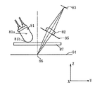
図8は、この色ずれを検出する為の画像検知装置の説明図である。
【0006】
図8では中間転写ベルトである記録部材84上に描写された位置検出用パターン(画像)86を光源手段81の発光部81aから放射され集光部81bで集光され、防塵ガラス87を介して照明している。
【0007】
位置検出パターン86で正反射した正反射光を防塵ガラス87、絞り85、結像レンズ82を介して受光手段83で検出している。
【0008】
受光手段83で検出された検出信号に従い各色の画像を出力すべく画像形成部(画像形成手段)を制御している。
【0009】
尚、図9は図8の画像検知装置において光源81から放射角度6.8°で放射された光束が受光手段83に入射する様子を示している。
【0010】
【発明が解決しようとする課題】
従来の画像検知装置は、光源の発光部と結像レンズの近傍に設けた絞りとの位置関係については何も特定されなかった。
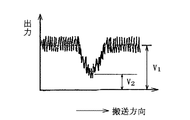
この為、図9に示した様に光源81からの極めてわずかな光束しかセンサー83へ入射しておらず、受光手段83より十分な信号出力を得る事ができないため、画像の検出精度に課題があった。図10は位置検出用マーク86を受光信号83で読み込んだ時の出力波形を示している。
【0011】
同図V1は記録部材からの正反射光を受けたときの出力信号であり、V2はトナー像(位置検出マーク)で描かれた検出用マークを受けたときの拡散光を受光したときの出力信号である。
【0012】
一般にこのときの信号出力値の比(SN比)V1/V2が大きい程検出精度が向上する。又、位置検出パターンの濃度を検出し、これより画像情報を得る画像検知装置を濃度検出装置として使用した場合の画像濃度と信号出力との関係を図11に示す。又、記録部材上での正反射光とトナーによる拡散光との関係を図12に示す。
【0013】
以下、図11、図12を参考して説明する。
【0014】
点Aに於いては記録部材上にトナーは一切乗っておらず記録部材からの正反射光だけがセンサーへ向かう。点Aから点Bまでの領域に於いては記録部材からの正反射光及び記録部材の一部に乗ったトナーからの拡散光がセンサーへ向う。この領域に於いてはトナー像により遮られる正反射光の光量がトナー像で拡散される拡散光の光量よりも多いため、単調減少する。
【0015】
更に点Bから点Cに至るまでの中間地点からはトナー像で拡散される拡散光の方が多くなり信号出力は増加するようになる。この逆転現象が発生する領域(グラフの点線より右側の領域)に於いては原理的に濃度を検知し画像情報を得る事ができない。
【0016】
一般には点Bから点Cに至る領域(中間調領域)が一番検出精度が必要とされるところであるがこの中間調領域での検出ができないという課題があった。
【0017】
本発明は各色の画像(位置検出用パターン)を検出し、これにより画像形成部を制御して多色現像を行ない画像を重ね合わせてカラー画像を得るとき、画像(位置検出パターン)検出用の画像検知装置の構成を適切に設定することにより、画像(位置検出パターン)の検出を高精度に行ない高品質のカラー画像が容易に得られる画像検知装置及び画像形成装置の提供を目的とする。
【0018】
【課題を解決するための手段】
請求項1の発明の画像検知装置は、光源手段と、前記光源手段から出射された光束を電子写真プロセスにより画像が形成された記録部材の上に照射する照明レンズと、受光手段と、前記記録部材上の画像を前記受光手段上に形成する結像レンズと、前記記録部材と前記受光手段の間の光路に配置された絞りと、を有し、
前記受光手段で得られた検出信号に基づいて前記記録部材上のフルカラー画像の位置情報及び濃度を検知する画像検知装置であって、
前記絞りの開口の大きさは、前記光源手段の発光点の像の大きさと同じであり、かつ、前記記録部材を鏡面反射面としたとき、前記光源手段の発光点と共役関係の位置に前記絞りが配置されていることを特徴としている。
【0019】
請求項2の発明は請求項1の発明において、前記光源手段の発光点がその共役位置に結像されるときの結像倍率をβとしたとき
1<|β|<7
であることを特徴としている。
【0020】
請求項3の発明は請求項1又は2の発明において、前記照明レンズの屈折力と前記結像レンズの屈折力は同一であることを特徴としている。
【0021】
請求項4の発明のカラー画像形成装置は、請求項1乃至3の何れか一項に記載の画像検知装置を有することを特徴としている。
【0026】
【発明の実施の形態】
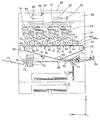
図1は本発明の画像検知装置を有した画像形成装置をデジタルフルカラー複写機に適用したときの実施形態1の要部概略図である。
【0027】
まず図1のデジタルフルカラー複写機の構成及び作用いついて説明する。
【0028】
図中、80は原稿読取部であり、原稿ガラス台86上に載置されたカラー画像の画像情報をミラー83,84,85,読取レンズ82によってによってCCD等の読取手段面81上に形成して読取っている。そして読取手段81からのカラー画像情報をフルカラー画像形成部10に入力している。
【0029】
フルカラー画像形成部10には第1〜第4の4つの画像ステーション(画像形成部(画像形成手段)Pa〜Pd)が配置され、各画像形成ステーション(Pa〜Pd)は像担持体として感光ドラム(2a〜2d)を有する。また、その周りには専用の帯電手段(3a〜3d)、画像情報に応じた光束を感光ドラム面上に照射するための走査光学装置(1a〜1d)、現像手段(5a〜5d)、ドラムクリーニング手段(4a〜4d)、そして転写手段(6a〜6d)等が各々配置されている。51a〜51dは各々現像剤容器であり、各現像手段(5a〜5d)に各々対応しており、走査光学装置(1a〜1d)の水平部の直下で、かつ垂直部に並んで設けられており、円柱形状の現像剤カートリッジを着脱することにより現像剤の補給を行うものである。
【0030】
ここで画像形成ステーション(Pa〜Pd)は各々シアン画像、マゼンダ画像、イエロー画像、ブラック画像を形成するところである。
【0031】
一方、各画像形成ステーションは(Pa〜Pd)を通過する態様で感光ドラム(2a〜2d)の下方に無端ベルト状の中間転写ベルト(記録部材)61が配置され、その中間転写ベルト61は駆動ローラ62と従動ローラ63及び65に帳架され、さらにその表面を清掃するクリーニング手段64が設けられている。
【0032】
本実施例における走査光学装置(1a〜1d)は光源手段としての半導体レーザ、該半導体レーザから出射した光束をポリゴンミラーに導光する入射光学手段、該ポリゴンミラーで偏向された光束を像担持体としての感光ドラム(2a〜2d)面上に結像させるトーリックレンズと球面レンズ、非球面レンズ等の光学素子とを有する結像手段、該トーリックレンズと光学素子との間に設けた反射部材としての反射ミラー、そしてそれらの光学要素を一体的に収容する収容手段を有している。
【0033】
このような構成において、まず第1の画像形成ステーションPaの帯電手段3a、走査光学装置1aによる露光等の公知の電子写真プロセス手段により感光ドラム2a面上に画像情報のシアン成分の潜像を形成した後、該潜像は現像手段5aでシアントナーを有する現像剤によりシアントナー像として可視像化され転写手段6aでシアントナー像が中間転写ベルト61の表面に転写される。
【0034】
一方、上記シアントナー像が中間転写ベルト61上に転写されている間に第2の画像形成ステーションPbではマゼンダ成分色の潜像が形成され、続いて現像手段5bでマゼンタトナーによるトナー像が得られ、先の第1の画像形成ステーションPaで転写が終了した中間転写ベルト61に転写手段6bにて精度よくマゼンタトナー像が重ねて転写される。
【0035】
以下、イエロー像、ブラック像、についても同様な方法で画像形成が行われ、中間転写ベルト61に4色のトナー像の重ね合わせが終了すると、中間転写ベルト61上の4色トナー像は2次転写ローラ66にて、給紙カセット70内にあって給紙ローラ71及び搬送ローラ対72、レジストローラ対73によりタイミングを合わせて搬送されたシート材S上に再び転写(2次転写)される。そして2次転写が終了したシート材Sは定着ローラ対74で転写されたトナー像が加熱定着され、シート材Sにフルカラー画像が得られる。そしてフルカラー画像が形成されたシート材Sはローラ75,76を介してトレー77に送られる。
【0036】
尚、転写が終了した各々の感光ドラム(2a〜2d)はクリーニング手段(4a〜4d)で各感光ドラム(2a〜2d)から残留トナーが除去され、引き続き行われる像形成に備えられる。
【0037】
69は画像検知装置である。同図において中間転写ベルト61の奥側、中央、手前側の3ヶ所又は奥側と手前の2ヶ所に同構成の画像検知装置が各々配置されている。
【0038】
尚、中間転写ベルト61の面は鏡面に近い状態となっている。
【0039】
本実施形態では、画像形成のプロセスを行う前に、各画像形成部Pa,Pb,Pc,Pdは中間転写ベルト61上にそれぞれ4つの画像形成部Pa,Pb,Pc,Pdに対応した画像としての位置検出用マーク(パターン)69aを形成する。
【0040】
即ち全体として各々4つの画像が形成されている。
以下は簡単のために位置検出マークは左右1つとして取扱う。
【0041】
画像検知装置69は、上述した画像形成部のプロセスを実行するに先立って各感光ドラム2a〜2dの非画像形成領域に形成され、そして中間転写ベルト61の搬送方向に転写された画像69aの位置情報を検出する。その検出された検出信号によって各画像形成部Pa,Pb,Pc,Pdは制御部(不図示)によって制御される。
【0042】
これによって色ずれのないカラー画像を中間転写ベルト61に形成している。
【0043】
図2は本発明の画像形成装置で用いている画像検知装置69の要部断面図であり、画像の位置情報又は濃度を検出している。図2は紙面方向が画像形成装置の主走査方向、(Y方向)紙面と垂直方向が中間転写ベルト(記録部材)の搬送方向(副走査方向)(X方向)を表している。
【0044】
31は中間転写ベルト61上に描画された位置検出用のトナー像(画像)69aを照明するためのLED光源である。31bは光源31の発光部31aからの光束を集光する集光部である。
【0045】
34は光源31から放射される光束を集光する為の照明手段を構成する照明レンズ、32は中間転写ベルト61からの正反射光及びトナー像69aからの拡散反射光を受光手段33に結像する為の結像手段を構成する結像レンズである。
【0046】
35は結像レンズ32近傍に設けた絞りである。
【0047】
27は防塵ガラスである。中間転写ベルト61を鏡面反射面としたとき、光源31の発光部(発光点)31aと絞り35は集光部31b、照明レンズ34等によって略共役関係となるようにしている。(ここで略とは完全に結像関係でなくとも本発明の目的を達成できる程度であれば良いことを意味している。)
尚、絞り35が結像レンズ32中にあるとき又は結像レンズ32より受光手段33側にあるときには発光部31aと絞り35は集光部31b、照明レンズ34そして結像レンズ32の一部又は全部によって略共役関係となるようにしている。
【0048】
これによって光源31からの光束でトナー像69aの照明を効率よく行ない、かつ中間転写ベルト61からの正反射光束が受光手段33に効率良く入射するようにしている。
【0049】
照明レンズ34及び集光部31bによる発光部31aの絞り35面上への結像倍率(発光部31aがその共役位置に結像されたときの結像倍率)βは
|β|=5.9
である。
【0050】
図3は図2の画像検知装置の受光手段33で得られる波形信号の説明図である。
【0051】
信号V1は中間転写ベルト61からの正反射光が受光手段に入射したときの信号値である。
【0052】
信号V2は位置検出パターン(トナー像)によって照明光が散乱され(正反射せず)受光手段33に入射する光量が減少したときの信号値である。
【0053】
本実施形態によれば信号のS/N比(V1/V2)が大きくなり、位置検出パターンの位置情報を高精度に検知することができる。
【0054】
図4は画像検知装置として位置検出パターン(トナー像)の濃度を検出し、濃度に応じて受光手段で得られる信号出力を示している。
【0055】
本実施形態によれば、画像(トナー像)の中間領域での逆転現像がなく、高精度に濃度を検出することができる。
【0056】
図5は本発明の画像形成装置で用いている画像検知装置の69の実施形態2の要部断面図であり、画像の位置情報又は濃度を検出している。図5は、紙面横方向が画像形成装置の主走査方向、(Y方向)紙面と垂直方向が中間転写ベルト(記録部材)の搬送方向(副走査方向)(X方向)を表している。
【0057】
31は中間転写ベルト61上に描画された位置検出用のトナー像(画像)を照明するためのLED光源である。30は光学素子であり、同一材質から成る結像レンズ32と照明レンズ34とを一体形成している。結像レンズ32はトナー像からの正反射光をセンサ(受光手段)33上に結像するための結像手段を構成する回転対称非球面を含むレンズである。
【0058】
また、照明レンズ34は光源31から放射される光束を集光するための照明手段を構成する回転対称非球面を含むレンズである。これによって照明効率と結像性能を向上させている。35は結像レンズ32近傍に設けた絞りである。照明レンズ34は集光部31bと、結像レンズ32とともに発光部31aと絞り35を略光学的共役関係としている。
【0059】
照明レンズ34と結像レンズ32の屈折力は同一であっても良く、又互いに異なるようにしても良い。
【0060】
照明レンズ34及び結像レンズ32は、それぞれの光軸34a,32aが検出用パターン69aを含む中間転写ベルト61に垂直な軸(面法線)69bに対して、反対方向に同じ角度傾斜している。
【0061】
図6は発光部の両端から放射される光線の光路を示したものである。本実施例のLED光線31の発光部31aのサイズは0.4×0.4mmであり、絞り35近傍に結像される発光部の像の大きさは2.0×2.0mm、すなわち結像倍率|β|は5.0である。絞り35の開口の大きさを発光部31aの像の大きさと同じでφ2.0mmとする事で、トナー像69a、からの拡散光を抑えながら、正反射光を効率良くセンサー33へ導くようにしている。
【0062】
又、結像倍率|β|を大きくする事で更に広い放射角の光線をセンサー上へ導く事も可能である。しかしその場合発光部が設計中心から微小にズレたとしても発光部の像が絞り上で大きく動くためLEDの取り付け敏感度が高くなってしまう。それゆえ結像倍率|β|は1倍以上7.0以下で使用するのが良い。
【0063】
即ち本発明においては結像倍率βは
1<|β|<7
とするのが良く、更に好ましくは
1.5<|β|<6
とするのが良い。
【0064】
本実施例ではこのように結像レンズ32と照明レンズ34そして絞りを形成することによって照明倍率と結像性能そして検知精度の向上を図っている。
【0065】
図7は本発明の画像検知装置の実施形態3の要部概略図である。
【0066】
本実施例は光源にチップタイプのLED71を使用している事が特徴であり、その他の作用は第1、第2の実施例と同様である。本実施例の結像レンズ32の結像倍率|β|は1.8である。結像倍率|β|が1.0以下となると十分出力を得る事ができず検出精度が悪化するので良くない。
【0067】
尚、以上の各実施形態において絞り35は結像レンズ32と受光手段33との間の他に、結像レンズ32中又は中間転写ベルト61と結像レンズ32との間のどこに配置しても良い。
【0068】
又、結像手段は照明手段からの光束のうち中間搬送ベルトの上のパターンからの反射光を集光して受光手段上に集光する反射型の代りに中間搬送ベルトのパターンを透過した光束を集光して受光手段上に導光する、透過型として各部材を構成しても良い。
【0069】
【発明の効果】
本発明によれば各色の画像(位置検出用パターン)を検出し、これにより画像形成部を制御して多色現像を行ない画像を重ね合わせてカラー画像を得るとき、画像(位置検出パターン)検出用の画像検知装置の構成を適切に設定することにより、画像(位置検出パターン)の検出を高精度に行ない高品質のカラー画像が容易に得られる画像検知装置及び画像形成装置を達成することができる。
【図面の簡単な説明】
【図1】本発明の画像形成装置の実施形態1の要部概略図。
【図2】本発明の画像検知装置の実施形態1の要部概略図。
【図3】本発明の画像検知装置で位置検出マークを読み込んだ時の信号波形の説明図。
【図4】本発明の画像検知装置で画像濃度と信号出力の関係を表す説明図。
【図5】本発明の画像検知装置の実施形態2の要部概略図。
【図6】本発明の画像検知装置の実施形態2の光路説明図。
【図7】本発明の画像検知装置の実施形態3の光路説明図。
【図8】従来の画像検知装置の要部概略図。
【図9】従来の画像検知装置の光路説明図。
【図10】従来の画像検知装置の位置検出マークを読み込んだ時の信号波形の説明図。
【図11】従来の画像検知装置の画像濃度と信号出力の関係を表す説明図。
【図12】記録部材上での正反射光とトナーの拡散光の説明図。
【符号の説明】
2a〜2d…感光ドラム
1a〜1d…光走査装置
61…中間転写ベルト
62…駆動ローラ
63…従動ローラ
69…画像検知装置
31…光源(LED)
31a…発光部
31b…レンズ面
32…結像レンズ
33…センサー
34…照明レンズ
35…絞り
Pa〜Pd…画像形成部
10…フルカラー画像形成部
80…原稿読取部
69a…位置検出パターン(画像)[0001]
BACKGROUND OF THE INVENTION
BACKGROUND OF THE INVENTION 1. Field of the Invention The present invention relates to an image detection apparatus and an image forming apparatus. For example, a multicolor image (color image) is formed by an electrophotographic copying machine, a laser beam printer, a color printer, a printing apparatus, etc. It is suitable for a color image forming apparatus for obtaining
[0002]
[Prior art]
A conventional image forming apparatus for obtaining a multicolor image generally forms images of different colors in a plurality of image forming units, for example, transports paper by a transport means such as a transport belt, and superimposes the images on the paper. The image was transferred to form a multicolor image. In particular, when a multicolor development is performed to obtain a full-color image, even a slight misalignment deteriorates. For example, if it is 400 dpi, even an overlap displacement of a fraction of 63.5 μm per pixel appears as a change in color misregistration or color misregistration and remarkably deteriorates the image.
[0003]
Conventionally, multi-color development is performed by using a single image forming unit, that is, the same scanning lens system, that is, optical scanning is performed with the same optical characteristics to reduce overlap of images.
However, this method has a problem that it takes time to output multiple images and full colors.
[0004]
In order to solve this problem, there is a method of forming images with different optical scanning devices in order to obtain images of each color separately, and superimposing the images of each color on the paper sent by the transport unit. However, the concern with this method is color misregistration when images are superimposed.
[0005]
FIG. 8 is an explanatory diagram of an image detection device for detecting this color misregistration.
[0006]
In FIG. 8, a position detection pattern (image) 86 drawn on a
[0007]
The regular reflection light regularly reflected by the
[0008]
The image forming unit (image forming unit) is controlled to output an image of each color in accordance with the detection signal detected by the
[0009]
FIG. 9 shows how the light beam emitted from the
[0010]
[Problems to be solved by the invention]
In the conventional image detection apparatus, nothing has been specified regarding the positional relationship between the light emitting portion of the light source and the diaphragm provided in the vicinity of the imaging lens.
For this reason, as shown in FIG. 9, since a very small amount of light from the
[0011]
FIG V1 is an output signal when subjected to regular reflection light from the recording member, V 2 is the time of receiving the diffused light when subjected to detection mark drawn by the toner image (the position detection mark) Output signal.
[0012]
In general, the detection accuracy improves as the ratio (SN ratio) V 1 / V 2 of the signal output value at this time increases. FIG. 11 shows the relationship between the image density and the signal output in the case where an image detection apparatus that detects the density of the position detection pattern and obtains image information from the position detection pattern is used as the density detection apparatus. FIG. 12 shows the relationship between the specularly reflected light on the recording member and the diffused light from the toner.
[0013]
Hereinafter, a description will be given with reference to FIGS.
[0014]
At point A, no toner is on the recording member and only specularly reflected light from the recording member is directed to the sensor. In the region from point A to point B, specularly reflected light from the recording member and diffused light from toner on a part of the recording member are directed to the sensor. In this region, the amount of specularly reflected light blocked by the toner image is larger than the amount of diffused light diffused by the toner image, and therefore monotonously decreases.
[0015]
Furthermore, from the intermediate point from point B to point C, the amount of diffused light diffused by the toner image increases, and the signal output increases. In the region where the reverse phenomenon occurs (the region on the right side of the dotted line in the graph), it is not possible in principle to detect the density and obtain image information.
[0016]
In general, the region from point B to point C (halftone region) is where the highest detection accuracy is required, but there is a problem that detection in this halftone region is not possible.
[0017]
The present invention detects an image (position detection pattern) for each color, and controls the image forming unit to perform multi-color development and superimpose the images to obtain a color image. An object of the present invention is to provide an image detection apparatus and an image forming apparatus that can detect an image (position detection pattern) with high accuracy and easily obtain a high-quality color image by appropriately setting the configuration of the image detection apparatus.
[0018]
[Means for Solving the Problems]
An image detection apparatus according to a first aspect of the present invention includes a light source unit, an illumination lens that irradiates a light beam emitted from the light source unit onto a recording member on which an image is formed by an electrophotographic process , a light receiving unit, and the recording unit. An imaging lens for forming an image on a member on the light receiving means, and a diaphragm disposed in an optical path between the recording member and the light receiving means,
An image detection device for detecting position information and density of a full-color image on the recording member based on a detection signal obtained by the light receiving means,
The size of the aperture of the diaphragm is the same as the size of the image of the light emitting point of the light source means, and when the recording member is a specular reflection surface, the size of the aperture is in a conjugate relationship with the light emitting point of the light source means. It is characterized by an aperture being arranged.
[0019]
According to a second aspect of the present invention, in the first aspect of the invention, 1 <| β | <7, where β is an imaging magnification when the light emitting point of the light source means is imaged at its conjugate position.
It is characterized by being.
[0020]
A third aspect of the invention is characterized in that, in the first or second aspect of the invention, the refractive power of the illumination lens and the refractive power of the imaging lens are the same.
[0021]
According to a fourth aspect of the present invention, a color image forming apparatus includes the image detection device according to any one of the first to third aspects .
[0026]
DETAILED DESCRIPTION OF THE INVENTION
FIG. 1 is a schematic view of the essential portions of Embodiment 1 when an image forming apparatus having an image detection apparatus of the present invention is applied to a digital full-color copying machine.
[0027]
First, the configuration and operation of the digital full-color copying machine of FIG. 1 will be described.
[0028]
In the figure,
[0029]
The full-color
[0030]
Here, the image forming stations (Pa to Pd) are for forming a cyan image, a magenta image, a yellow image, and a black image, respectively.
[0031]
On the other hand, an endless belt-like intermediate transfer belt (recording member) 61 is disposed below the photosensitive drums (2a to 2d) so that each image forming station passes (Pa to Pd), and the
[0032]
The scanning optical apparatus (1a to 1d) in this embodiment includes a semiconductor laser as a light source means, incident optical means for guiding a light beam emitted from the semiconductor laser to a polygon mirror, and a light beam deflected by the polygon mirror as an image carrier. As an imaging means having a toric lens that forms an image on the surface of the photosensitive drum (2a to 2d) and an optical element such as a spherical lens or an aspheric lens, and a reflecting member provided between the toric lens and the optical element And a receiving means for integrally receiving these optical elements.
[0033]
In such a configuration, first, a latent image of the cyan component of the image information is formed on the surface of the
[0034]
On the other hand, a magenta component color latent image is formed at the second image forming station Pb while the cyan toner image is being transferred onto the
[0035]
Thereafter, image formation is performed in the same manner for the yellow image and the black image, and when the four color toner images are superimposed on the
[0036]
Each of the photosensitive drums (2a to 2d) after transfer is removed from the photosensitive drums (2a to 2d) by the cleaning means (4a to 4d), and is prepared for subsequent image formation.
[0037]
[0038]
The surface of the
[0039]
In the present embodiment, before performing the image forming process, the image forming portions Pa, Pb, Pc, and Pd are formed on the
[0040]
That is, four images are formed as a whole.
For the sake of simplicity, the position detection marks are handled as one on the left and right.
[0041]
[0042]
As a result, a color image without color misregistration is formed on the
[0043]
FIG. 2 is a cross-sectional view of the main part of the
[0044]
31 is an LED light source for illuminating the toner image for the detected position drawn on the intermediate transfer belt 61 (image) 69a. 31b is a condensing part which condenses the light beam from the
[0045]
[0046]
A
[0047]
When the
[0048]
Thus, the
[0049]
Imaging magnification on the surface of the
It is.
[0050]
FIG. 3 is an explanatory diagram of a waveform signal obtained by the light receiving means 33 of the image detection apparatus of FIG.
[0051]
The signal V1 is a signal value when the regular reflection light from the
[0052]
The signal V2 is a signal value when the illumination light is scattered (not regularly reflected) by the position detection pattern (toner image) and the amount of light incident on the light receiving means 33 is reduced.
[0053]
According to the present embodiment, the S / N ratio ( V1 / V2 ) of the signal increases, and the position information of the position detection pattern can be detected with high accuracy.
[0054]
FIG. 4 shows the signal output obtained by the light receiving means according to the density of the position detection pattern (toner image) detected by the image detection apparatus.
[0055]
According to this embodiment, there is no reverse development in an intermediate region of an image (toner image), and the density can be detected with high accuracy.
[0056]
FIG. 5 is a cross-sectional view of an essential part of Embodiment 2 of the
[0057]
[0058]
The
[0059]
The refracting power of the
[0060]
The
[0061]
FIG. 6 shows an optical path of light rays emitted from both ends of the light emitting unit. In this embodiment, the size of the
[0062]
It is also possible to guide a light beam having a wider radiation angle onto the sensor by increasing the imaging magnification | β |. However, in that case, even if the light emitting portion is slightly deviated from the design center, the image of the light emitting portion moves greatly on the stop, so that the LED mounting sensitivity becomes high. Therefore, the imaging magnification | β | is preferably used in the range of 1 to 7.0.
[0063]
That is, in the present invention, the imaging magnification β is 1 <| β | <7
More preferably, 1.5 <| β | <6
It is good to do.
[0064]
In this embodiment, the
[0065]
FIG. 7 is a schematic view of the essential portions of Embodiment 3 of the image detection apparatus of the present invention.
[0066]
This embodiment is characterized in that a chip-
[0067]
In each of the above embodiments, the
[0068]
Further, the image forming means condenses the reflected light from the pattern on the intermediate transport belt out of the light flux from the illuminating means and transmits the light through the pattern of the intermediate transport belt instead of the reflection type for condensing on the light receiving means. Each member may be configured as a transmission type that collects light and guides the light onto the light receiving means.
[0069]
【Effect of the invention】
According to the present invention, an image (position detection pattern) is detected when an image (position detection pattern) of each color is detected and a color image is obtained by performing multicolor development by controlling the image forming unit and superimposing the images. By appropriately setting the configuration of the image detection apparatus for use, it is possible to achieve an image detection apparatus and an image forming apparatus that can detect an image (position detection pattern) with high accuracy and easily obtain a high-quality color image. it can.
[Brief description of the drawings]
FIG. 1 is a schematic diagram of a main part of an image forming apparatus according to a first embodiment of the present invention.
FIG. 2 is a schematic diagram of a main part of Embodiment 1 of the image detection apparatus of the present invention.
FIG. 3 is an explanatory diagram of signal waveforms when a position detection mark is read by the image detection apparatus of the present invention.
FIG. 4 is an explanatory diagram showing the relationship between image density and signal output in the image detection apparatus of the present invention.
FIG. 5 is a main part schematic diagram of Embodiment 2 of an image detection apparatus of the present invention;
FIG. 6 is an explanatory diagram of an optical path of the image detection apparatus according to the second embodiment of the present invention.
FIG. 7 is an optical path explanatory diagram of Embodiment 3 of the image detection apparatus of the present invention.
FIG. 8 is a main part schematic diagram of a conventional image detection apparatus.
FIG. 9 is an explanatory diagram of an optical path of a conventional image detection apparatus.
FIG. 10 is an explanatory diagram of signal waveforms when a position detection mark of a conventional image detection apparatus is read.
FIG. 11 is an explanatory diagram showing the relationship between image density and signal output of a conventional image detection apparatus.
FIG. 12 is an explanatory diagram of regular reflection light and toner diffusion light on a recording member.
[Explanation of symbols]
2a to 2d ... photosensitive drums 1a to 1d ...
31a ...
Claims (4)
前記受光手段で得られた検出信号に基づいて前記記録部材上のフルカラー画像の位置情報及び濃度を検知する画像検知装置であって、
前記絞りの開口の大きさは、前記光源手段の発光点の像の大きさと同じであり、かつ、前記記録部材を鏡面反射面としたとき、前記光源手段の発光点と共役関係の位置に前記絞りが配置されている
ことを特徴とする画像検知装置。A light source means, an illumination lens that irradiates a light beam emitted from the light source means onto a recording member on which an image is formed by an electrophotographic process , a light receiving means, and an image on the recording member is formed on the light receiving means. An imaging lens, and a diaphragm disposed in an optical path between the recording member and the light receiving means,
An image detection device for detecting position information and density of a full-color image on the recording member based on a detection signal obtained by the light receiving means,
The size of the aperture of the diaphragm is the same as the size of the image of the light emitting point of the light source means, and when the recording member is a specular reflection surface, the size of the aperture is in a conjugate relationship with the light emitting point of the light source means. An image detection apparatus having an aperture.
1<|β|<7
であることを特徴とする請求項1に記載の画像検知装置。1 <| β | <7, where β is the imaging magnification when the light emitting point of the light source means is imaged at its conjugate position
The image detection apparatus according to claim 1, wherein:
Priority Applications (2)
| Application Number | Priority Date | Filing Date | Title |
|---|---|---|---|
| JP2000241784A JP4944290B2 (en) | 2000-08-09 | 2000-08-09 | Image detecting apparatus and image forming apparatus |
| US09/922,643 US6873804B2 (en) | 2000-08-09 | 2001-08-07 | Image sensing device |
Applications Claiming Priority (1)
| Application Number | Priority Date | Filing Date | Title |
|---|---|---|---|
| JP2000241784A JP4944290B2 (en) | 2000-08-09 | 2000-08-09 | Image detecting apparatus and image forming apparatus |
Publications (3)
| Publication Number | Publication Date |
|---|---|
| JP2002055572A JP2002055572A (en) | 2002-02-20 |
| JP2002055572A5 JP2002055572A5 (en) | 2007-09-13 |
| JP4944290B2 true JP4944290B2 (en) | 2012-05-30 |
Family
ID=18732923
Family Applications (1)
| Application Number | Title | Priority Date | Filing Date |
|---|---|---|---|
| JP2000241784A Expired - Fee Related JP4944290B2 (en) | 2000-08-09 | 2000-08-09 | Image detecting apparatus and image forming apparatus |
Country Status (1)
| Country | Link |
|---|---|
| JP (1) | JP4944290B2 (en) |
Families Citing this family (7)
| Publication number | Priority date | Publication date | Assignee | Title |
|---|---|---|---|---|
| US7443535B2 (en) | 2002-03-25 | 2008-10-28 | Ricoh Company, Limited | Misalignment correction pattern formation method and misalignment correction method |
| JP5709458B2 (en) * | 2009-12-21 | 2015-04-30 | キヤノン株式会社 | Detection apparatus and image forming apparatus |
| JP5725731B2 (en) * | 2010-05-13 | 2015-05-27 | キヤノン株式会社 | Image detecting apparatus and image forming apparatus having the same |
| JP5327302B2 (en) | 2011-10-12 | 2013-10-30 | 富士ゼロックス株式会社 | Reflective sensor and image forming apparatus |
| JP6015311B2 (en) | 2012-09-28 | 2016-10-26 | 富士ゼロックス株式会社 | Image forming apparatus and program |
| JP5966823B2 (en) | 2012-09-28 | 2016-08-10 | 富士ゼロックス株式会社 | Detection apparatus and image forming apparatus |
| JP6171973B2 (en) * | 2014-02-13 | 2017-08-02 | 富士ゼロックス株式会社 | Image detecting apparatus and image forming apparatus |
Family Cites Families (3)
| Publication number | Priority date | Publication date | Assignee | Title |
|---|---|---|---|---|
| JPS52102772A (en) * | 1976-02-24 | 1977-08-29 | Masahiro Yamada | Water clock |
| JPS5537884A (en) * | 1978-09-09 | 1980-03-17 | Hitachi Ltd | Stator for rotary electric machine |
| JP3027161B2 (en) * | 1989-07-14 | 2000-03-27 | 株式会社リコー | Image density detecting device in image forming apparatus |
-
2000
- 2000-08-09 JP JP2000241784A patent/JP4944290B2/en not_active Expired - Fee Related
Also Published As
| Publication number | Publication date |
|---|---|
| JP2002055572A (en) | 2002-02-20 |
Similar Documents
| Publication | Publication Date | Title |
|---|---|---|
| JP3072018B2 (en) | Image forming device | |
| JP3253227B2 (en) | Image forming device | |
| US6493010B1 (en) | Color image forming apparatus for forming a plurality of single-color images on a latent image carrier | |
| JP2010114498A (en) | Image forming apparatus and image reading apparatus | |
| US20070216969A1 (en) | Image reading apparatus and image forming apparatus | |
| JP2004219849A (en) | Synchronization detection device, optical scanning device and image forming device | |
| US6873804B2 (en) | Image sensing device | |
| JP5709458B2 (en) | Detection apparatus and image forming apparatus | |
| JP4944290B2 (en) | Image detecting apparatus and image forming apparatus | |
| JP5725731B2 (en) | Image detecting apparatus and image forming apparatus having the same | |
| US6101359A (en) | Image forming apparatus | |
| JP2011107524A (en) | Optical device, displacement detection sensor, and image forming apparatus | |
| JP4717189B2 (en) | Image forming apparatus | |
| US10908544B2 (en) | Discriminating device and image forming apparatus | |
| JP2019033334A (en) | Reading module and image forming apparatus including the same | |
| JP5402441B2 (en) | Reflective optical sensor and image forming apparatus | |
| JP2008139352A (en) | Light scanning optical device | |
| JP2002098922A (en) | Optical scanner | |
| JPH05119574A (en) | Color image forming device | |
| JP2006215352A (en) | Image forming apparatus | |
| JP4933970B2 (en) | Scanning optical apparatus and image forming apparatus | |
| JPH11272038A (en) | Image forming device | |
| JP2002054904A (en) | Image detecting device and image forming device | |
| JP2019144313A (en) | Image formation apparatus | |
| JP3734116B2 (en) | Position shift amount detection device for superimposed image |
Legal Events
| Date | Code | Title | Description |
|---|---|---|---|
| A521 | Written amendment |
Free format text: JAPANESE INTERMEDIATE CODE: A523 Effective date: 20070730 |
|
| A621 | Written request for application examination |
Free format text: JAPANESE INTERMEDIATE CODE: A621 Effective date: 20070730 |
|
| A977 | Report on retrieval |
Free format text: JAPANESE INTERMEDIATE CODE: A971007 Effective date: 20100401 |
|
| A131 | Notification of reasons for refusal |
Free format text: JAPANESE INTERMEDIATE CODE: A131 Effective date: 20100518 |
|
| A521 | Written amendment |
Free format text: JAPANESE INTERMEDIATE CODE: A523 Effective date: 20100714 |
|
| A02 | Decision of refusal |
Free format text: JAPANESE INTERMEDIATE CODE: A02 Effective date: 20101026 |
|
| A521 | Written amendment |
Free format text: JAPANESE INTERMEDIATE CODE: A523 Effective date: 20110124 |
|
| A911 | Transfer of reconsideration by examiner before appeal (zenchi) |
Free format text: JAPANESE INTERMEDIATE CODE: A911 Effective date: 20110128 |
|
| A912 | Removal of reconsideration by examiner before appeal (zenchi) |
Free format text: JAPANESE INTERMEDIATE CODE: A912 Effective date: 20110318 |
|
| A521 | Written amendment |
Free format text: JAPANESE INTERMEDIATE CODE: A523 Effective date: 20120124 |
|
| A01 | Written decision to grant a patent or to grant a registration (utility model) |
Free format text: JAPANESE INTERMEDIATE CODE: A01 |
|
| A61 | First payment of annual fees (during grant procedure) |
Free format text: JAPANESE INTERMEDIATE CODE: A61 Effective date: 20120302 |
|
| R151 | Written notification of patent or utility model registration |
Ref document number: 4944290 Country of ref document: JP Free format text: JAPANESE INTERMEDIATE CODE: R151 |
|
| FPAY | Renewal fee payment (event date is renewal date of database) |
Free format text: PAYMENT UNTIL: 20150309 Year of fee payment: 3 |
|
| LAPS | Cancellation because of no payment of annual fees |