JP4943645B2 - Boom length detector for telescopic boom - Google Patents
Boom length detector for telescopic boom Download PDFInfo
- Publication number
- JP4943645B2 JP4943645B2 JP2004329291A JP2004329291A JP4943645B2 JP 4943645 B2 JP4943645 B2 JP 4943645B2 JP 2004329291 A JP2004329291 A JP 2004329291A JP 2004329291 A JP2004329291 A JP 2004329291A JP 4943645 B2 JP4943645 B2 JP 4943645B2
- Authority
- JP
- Japan
- Prior art keywords
- boom
- telescopic
- cord
- telescopic boom
- length
- Prior art date
- Legal status (The legal status is an assumption and is not a legal conclusion. Google has not performed a legal analysis and makes no representation as to the accuracy of the status listed.)
- Active
Links
Images

Landscapes
- Jib Cranes (AREA)
Description
本発明は、旋回ポストに起伏自在に枢支された基端ブーム内に複数の先端側ブームを伸縮自在に嵌挿してなる伸縮ブームのブーム長さ(伸長量)を検出するブーム長さ検出器に関するものである。 The present invention relates to a boom length detector for detecting a boom length (extension amount) of a telescopic boom that is formed by inserting a plurality of front end side booms in a base boom that is pivotably supported by a swing post. It is about.
移動式クレーンや高所作業車等のブーム式作業車に装備されている伸縮ブームは、旋回ポストに起伏自在に枢支された基端ブーム内に複数の先端側ブームを伸縮自在に嵌挿して構成されており、そのブーム長さ(伸長量)は作業者が実際の稼働状態を把握する場合や、作業車が過負荷状態になるのを防止する過負荷防止制御を行う場合に重要な要素の一つであり、ブーム長さ検出器によって検出していた。 The telescopic booms equipped on boom-type work vehicles such as mobile cranes and aerial work platforms have a plurality of booms that are telescopically inserted into a base boom that is pivotably supported by a swing post. The boom length (extension amount) is an important factor when the operator grasps the actual operating state or when overload prevention control is performed to prevent the work vehicle from becoming overloaded. It was detected by a boom length detector.
従来、この種の伸縮ブームに用いられるブーム長さ検出器bは、図3に示す如く一端を最先端側ブーム7aに止着して伸縮ブーム7内に張設した測長用コードdと、当該測長用コードdを繰出し自在に巻取りブーム伸縮動に伴う当該コードdの繰出しに応じて回転する巻取りリールの回転変位を回転変位検出手段fで検出してブーム長さ信号として出力するコード巻取り器eとで構成されていた。当該ブーム長さ検出器bは、伸縮ブーム7が伸縮動して最先端側ブーム7aの相対位置が変化した際に、当該ブーム7aに一端を止着して張設した測長用コードdが引出されて巻取りリールが回転し、この巻取りリールの回転変位を回転変位検出手段fで検出してブーム長さ信号として出力するようになっている。そして、コード巻取り器eは、測長用コードdがクレーン作業時に障害物(作業現場の鉄骨等)に接触して損傷するのを避けるため伸縮ブーム7内に張設されていること、回転変位検出手段fが電気的ノイズの影響を受け易いことから伸縮ブーム7の基端部7bに取付けられていた(例えば、特許文献1参照)。
しかしながら、このようにコード巻取り器eを伸縮ブーム7の基端部7bに取付ける場合には、伸縮ブームの外形寸法が比較的大きくブーム後端面に充分な機器取付けスペースが確保できる場合(例えば、特許文献1記載の伸縮ブーム)には容易に適応可能であるが、外形寸法の小さな小型クレーン、例えばトラックの運転室と荷台間に搭載されて主として荷台上への貨物の積降し作業に用いられる車輌搭載型クレーンに適応する場合には、ブーム後方や上方への突出量が大きくなるという問題があった。すなわち、外形寸法の小さな伸縮ブーム7に図3に示す如くコード巻取り器eを取付けた場合には、伸縮ブーム7に対するコード巻取り器eの大きさが相対的に大きくなり、ブーム起仰状態(図3一点鎖線図示状態)におけるブーム後端面からの後方突出量sが大きくなり、トラック1の運転室2や荷台3の鳥居3a等に接触してコード巻取り器eが損傷する恐れがあった。また、ブーム最倒伏状態(車輌走行状態;図3実線図示状態)でブーム上面からの上方突出量uが大きく、橋梁下や工場建屋入口等を通過する際に梁等に接触して損傷する恐れがあった。
However, when the cord winder e is attached to the base end portion 7b of the
本発明は、上記課題に鑑みてなしたものであり、外形寸法の小さな小型クレーン用の伸縮ブームであってもコード巻取り器が伸縮ブームから大きく突出しないように構成して、障害物との接触による損傷を少なくした伸縮ブームのブーム長さ検出器を提供することを目的としている。 The present invention has been made in view of the above problems, and is configured so that the cord winder does not protrude greatly from the telescopic boom even when the telescopic boom is for a small crane having a small external dimension. An object of the present invention is to provide a boom length detector for a telescopic boom that is less damaged by contact.
本発明は、上記課題を解決するための手段として、次の如き構成を有している。 The present invention has the following configuration as means for solving the above problems.
すなわち、本発明の伸縮ブームのブーム長さ検出器は、基端下部位置を旋回ポストの上部に起伏自在に枢支した筒状形状の基端ブーム内に複数の先端側ブームを伸縮自在に嵌挿してなる伸縮ブームと、一端を最先端側ブームに止着して伸縮ブーム内に張設した測長用コード、当該測長用コードを繰出し自在に巻取りブーム伸縮動に伴う当該コードの繰出しに応じて回転する巻取りリールの回転変位を回転変位検出手段で検出してブーム長さ信号として出力するコード巻取り器とで構成した伸縮ブームのブーム長さ検出器を対象にしている。
In other words, the boom length detector of the telescopic boom of the present invention has a plurality of front-end booms that can be telescopically fitted in a cylindrical base end boom that pivotally supports the lower position of the base end on the upper part of the swivel post. The telescopic boom that is inserted, the length measuring cord that is fastened to the end boom on one end, and stretched in the telescopic boom, and the cord is fed out along with the retracting movement of the retractable boom The boom length detector of the telescopic boom is composed of a cord winder that detects the rotational displacement of the take-up reel that rotates in response to the rotational displacement detection means and outputs it as a boom length signal.
そして、本発明のブーム長さ検出器は、伸縮ブームの基端上部にブーム起仰状態において後方に突出しないよう斜めに切欠いた切欠き部を設け、この切欠き空間にブーム最倒伏状態においてブーム上面から上方に突出しないよう前記コード巻取り器を取付けて構成している。 The boom length detector according to the present invention is provided with a notch that is obliquely cut out so as not to protrude rearward when the boom is raised, at the base end upper part of the telescopic boom. The cord winder is attached so as not to protrude upward from the upper surface.
このように構成したブーム長さ検出器によれば、伸縮ブームの基端上部にブーム起仰状態において後方に突出しないよう斜めに切欠いた切欠き部を設け、この切欠き空間内にブーム最倒伏状態においてブーム上面から上方に突出しないようコード巻取り器を取付けたので、例え外形形状の小さな伸縮ブームでコード巻取り器が相対的に大きな場合であっても、従来のものに比しブーム後端面からの突出量を少なくすることができるのである。このため、ブーム起仰状態においてブーム後方への突出量が相対的に少なくなり、トラックの運転室や荷台の鳥居等への接触が未然に防止できるのである。また、ブーム最倒伏状態においてブーム上面からの上方突出がなくなり、橋梁下や工場建屋入口等を通過する際の梁等への接触が未然に防止でき、修理費用の低減ができるのである。 According to the boom length detector configured as described above, a notch portion that is notched obliquely so as not to protrude rearward when the boom is raised is provided at the upper base end of the telescopic boom, and the boom is most collapsed in the notch space. Since the cord winder is mounted so that it does not protrude upward from the upper surface of the boom in the state, even if the cord winder is relatively large with a telescopic boom with a small outer shape, The amount of protrusion from the end face can be reduced. For this reason, the amount of protrusion to the rear of the boom is relatively small when the boom is raised, and contact with the cab of the truck or the torii of the loading platform can be prevented. Further, when the boom is in the most collapsed state, there is no upward protrusion from the upper surface of the boom, and contact with the beam or the like when passing under the bridge or the factory building entrance or the like can be prevented beforehand, and the repair cost can be reduced.
以下、本発明の好ましい実施形態について、図1〜図3に基づき説明する。 Hereinafter, a preferred embodiment of the present invention will be described with reference to FIGS.
図2において、Aはトラック1の運転室2と荷台3間に搭載した車輌搭載型クレーンであり、左右に張出して設置可能なアウトリガ装置4,4を備えたクレーン基台5と、当該クレーン基台5上に旋回駆動手段(図示せず)によって旋回自在に取付けられた旋回ポスト6、当該旋回ポスト6の上部に起伏シリンダ11によって起伏自在に枢支され基端ブーム7-1内に複数の先端側ブーム7-2,7-3・・を伸縮自在に嵌挿した伸縮ブーム7、当該伸縮ブーム7に内装され基端ブーム7-1に対し先端側ブーム7-2,7-3・・を伸縮駆動する伸縮シリンダ12、旋回ポスト6あるいは基端ブーム7-1に取付けたウインチ装置8から繰出したワイヤロープ9によって伸縮ブーム先端部7aから巻上げ巻下げ自在に吊下した荷役用フックブロック10とで構成されている。
In FIG. 2, A is a vehicle-mounted crane mounted between the cab 2 and the
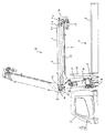
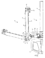
伸縮ブーム7は、図1に示す如く基端ブーム7-1内に複数の先端側ブーム7-2,7-3・・を伸縮自在に嵌挿して構成されており、内装した伸縮シリンダ12によって基端ブーム7-1に対し先端側ブーム7-2,7-3・・が伸縮動して、ブーム長さL(伸長量)が変化するようになっている。また、起伏シリンダ11の駆動によって最倒伏状態(図2実線図示状態)と起仰状態(図2一点鎖線図示状態)との間で起伏駆動可能になっている。
As shown in FIG. 1, the
Bは、伸縮ブーム7のブーム長さLを検出するブーム長さ検出器である。当該ブーム長さ検出器Bは、測長用コード13とコード巻取り器14とで構成されている。測長用コード13は、コード巻取り器14の巻取りリール14aに繰出し自在に巻取られており、当該リール14aから繰出されたコード13の一端13aは伸縮ブーム7内を経過して最先端側ブーム7-3の先端部適所に止着されている。コード巻取り器14は、前記測長用コード13を繰出し自在に巻取った巻取りリール14aと、伸縮ブーム7の伸縮動に伴うコード13の引出しに応じて回転する巻取りリール14aの回転変位をポテンショメータ等の検出器を用いて電気的に検出する回転変位検出手段15とで構成されている。このように構成されたブーム長さ検出器Bは、伸縮ブーム7が伸縮動してブーム長さが変化すれば、これに伴って一端13aを最先端側ブーム7-3に止着した測長用コード13が引出されて巻取りリール14aが回転し、この巻取りリール14aの回転変位を回転変位検出手段15で検出してブーム長さ信号として出力するようになっている。これにより、ブーム長さLが検出されるのである。そして、当該ブーム長さ検出器Bで検出されたブーム長さ信号は、作業車の実際の稼働状態を表示する稼働状態表示器(図示せず)に入力してブーム長さの実際値表示に利用可能である他、作業車が過負荷状態になるのを防止する過負荷防止装置(図示せず)に入力して過負荷防止制御に利用可能である。
B is a boom length detector that detects the boom length L of the
伸縮ブーム7の基端上部には、ブーム起仰状態において後方に突出しないよう斜めに切欠いた切欠き部C(図1斜線図示部分)が設けられている。そして、この切欠き空間Cにブーム最倒伏状態(車輌走行状態)においてブーム上面7cから上方に突出しないよう前記巻取りリール14aが取付けられている。20は、伸縮ブーム7の後端面7dに立設したリール取付け用の取付けブラケットである。また、21は巻取りリール14aを保護するカバーである。
At the base end upper part of the
ブーム長さ検出器Bのコード巻取り器14は、このように伸縮ブーム7の基端上部に設けた切欠き空間Cに、ブーム最倒伏状態においてブーム上面7cから上方に突出しないよう取付けられているので、例え外形形状の小さな伸縮ブーム7でコード巻取り器14が相対的に大きな場合でも、この切欠き空間C内から大きく後方に突出することなくコード巻取り器14を取付けることができるのである。このため、ブーム起仰状態においてコード巻取り器14のブーム後方への突出が少なくなり、トラック1の運転室2や荷台3の鳥居3a等への接触が防止できるのである(図2一点鎖線図示状態)。また、ブーム最倒伏状態においてブーム上方への突出がなくなり、トラック1が橋梁下や工場建屋入口等を通過する際に梁等への接触が防止できるのである(図2実線図示状態)。これにより、作業機の修理費用(維持費)を可及的に少なくすることができるのである。
The
また、16は最先端側ブーム7-3のブーム上板内面に長手方向に沿って設けたコード支持用のパイプであり、張設状態の測長用コード13を収容してコード揺動によるブーム内構造物(例えば、伸縮シリンダ12等)への接触で損傷しないよう案内するためのものである。また、17,18は、夫々基端ブーム7-1の基端部と中間位の先端側ブーム7-2基端部に取付けた案内ローラであり、張設状態の測長用コード13を支持して弛みを防止すると共に、測長用コード13が巻取りリール14aに整然と巻取られるよう案内するためのものである。
Reference numeral 16 denotes a cord support pipe provided along the longitudinal direction on the inner surface of the boom upper plate of the most advanced boom 7-3. It is for guiding so as not to be damaged by contact with the internal structure (for example, the telescopic cylinder 12).
このように構成した本発明のブーム長さ検出器は、伸縮ブーム7の基端上部にブーム起仰状態において後方に突出しないよう斜めに切欠いた切欠き部Cを設け、この切欠き空間C内にブーム最倒伏状態においてブーム上面7cから上方に突出しないようコード巻取り器14を取付けて構成したので、例え外形形状が小さな伸縮ブーム7でコード巻取り器14が相対的に大きな場合であっても、ブーム後方に大きく突出することなくコード巻取り器14を取付けることができ、障害物との接触によるブーム長さ検出器の損傷を効果的に少なくすることができるのである。
The boom length detector of the present invention configured as described above is provided with a notch C cut obliquely so as not to protrude rearward when the boom is raised, at the upper base end of the
A 車輌搭載型クレーン、
B ブーム長さ検出器、
C 切欠き部(切欠き空間)、
1 トラック、
2 運転室、
3 荷台、
3a 鳥居、
4 アウトリガ装置、
5 クレーン基台、
6 旋回ポスト、
7 伸縮ブーム、
8 ウインチ装置、
9 ワイヤロープ、
10 フックブロック、
11 起伏シリンダ、
12 伸縮シリンダ、
13 測長用コード、
14 コード巻取り器、
14a 巻取りリール、
15 回転変位検出手段、
A vehicle-mounted crane,
B Boom length detector,
C Notch (notch space),
1 track,
2 cab,
3 cargo bed,
3a Torii
4 Outrigger device,
5 Crane base,
6 swivel post,
7 telescopic boom,
8 winch device,
9 Wire rope,
10 hook block,
11 Rolling cylinder,
12 telescopic cylinder,
13 Measuring code,
14 Cord winder,
14a take-up reel,
15 rotational displacement detection means,
Claims (1)
前記伸縮ブームの基端上部にブーム起仰状態において後方に突出しないよう斜めに切欠いた切欠き部を設け、この切欠き空間にブーム最倒伏状態においてブーム上面から上方に突出しないよう前記コード巻取り器を取付けて構成したことを特徴とする伸縮ブームのブーム長さ検出器。 A telescopic boom with a plurality of telescopic booms telescopically inserted into a tubular base end boom that pivotally supports the lower position of the base end on the upper part of the swivel post, and one end fixed to the most advanced boom Measures the length measurement cord that is worn and stretched in the telescopic boom, and detects the rotational displacement of the take-up reel that rotates in response to the extension of the cord along with the telescopic motion of the take-up boom. In the boom length detector of the telescopic boom composed of a cord winder that detects by means and outputs as a boom length signal,
A notch is provided at the upper base end of the telescopic boom so as not to protrude rearward when the boom is raised, and the cord winding is performed in the notch space so as not to protrude upward from the upper surface of the boom when the boom is in the most collapsed state. A boom length detector for a telescopic boom, characterized in that the device is mounted.
Priority Applications (1)
| Application Number | Priority Date | Filing Date | Title |
|---|---|---|---|
| JP2004329291A JP4943645B2 (en) | 2004-11-12 | 2004-11-12 | Boom length detector for telescopic boom |
Applications Claiming Priority (1)
| Application Number | Priority Date | Filing Date | Title |
|---|---|---|---|
| JP2004329291A JP4943645B2 (en) | 2004-11-12 | 2004-11-12 | Boom length detector for telescopic boom |
Publications (2)
| Publication Number | Publication Date |
|---|---|
| JP2006137565A JP2006137565A (en) | 2006-06-01 |
| JP4943645B2 true JP4943645B2 (en) | 2012-05-30 |
Family
ID=36618621
Family Applications (1)
| Application Number | Title | Priority Date | Filing Date |
|---|---|---|---|
| JP2004329291A Active JP4943645B2 (en) | 2004-11-12 | 2004-11-12 | Boom length detector for telescopic boom |
Country Status (1)
| Country | Link |
|---|---|
| JP (1) | JP4943645B2 (en) |
Families Citing this family (3)
| Publication number | Priority date | Publication date | Assignee | Title |
|---|---|---|---|---|
| JP5725777B2 (en) * | 2010-09-17 | 2015-05-27 | 株式会社タダノ | Cord reel mounting structure |
| JP6531505B2 (en) * | 2015-06-11 | 2019-06-19 | 株式会社タダノ | Telescopic boom mounting structure |
| KR101975697B1 (en) * | 2015-06-11 | 2019-05-07 | 가부시기가이샤다다노 | Mounting structure of new boom |
Family Cites Families (7)
| Publication number | Priority date | Publication date | Assignee | Title |
|---|---|---|---|---|
| JPS4915662A (en) * | 1972-06-03 | 1974-02-12 | ||
| JPS5437376B2 (en) * | 1973-03-27 | 1979-11-14 | ||
| JPS51126164A (en) * | 1975-04-25 | 1976-11-04 | Nippon Globe Kk | Device for measuring expansion multistage boom |
| JPS6056210A (en) * | 1983-09-07 | 1985-04-01 | Diesel Kiki Co Ltd | Position detector for vehicle |
| JPH07291589A (en) * | 1994-04-22 | 1995-11-07 | Furukawa Co Ltd | Overload prevention device for crane |
| JP2000034092A (en) * | 1998-07-16 | 2000-02-02 | Kobe Steel Ltd | Telescopic boom |
| JP2002284483A (en) * | 2001-03-29 | 2002-10-03 | Tadano Ltd | On-vehicle crane |
-
2004
- 2004-11-12 JP JP2004329291A patent/JP4943645B2/en active Active
Also Published As
| Publication number | Publication date |
|---|---|
| JP2006137565A (en) | 2006-06-01 |
Similar Documents
| Publication | Publication Date | Title |
|---|---|---|
| JP5006622B2 (en) | Crane device with telescopic boom | |
| US11702325B2 (en) | Method for controlling crane, and crane | |
| US11053105B2 (en) | Crane vehicle | |
| JP2011121731A (en) | Working machine with boom | |
| WO2020085314A1 (en) | Crane device, method for determining number of falls, and program | |
| JP5739491B2 (en) | Floor crane | |
| JP4943645B2 (en) | Boom length detector for telescopic boom | |
| JP2004250155A (en) | Rope winch | |
| JP5725777B2 (en) | Cord reel mounting structure | |
| JP5121352B2 (en) | Mobile crane | |
| JP5121351B2 (en) | Mobile crane | |
| JP5531769B2 (en) | Jib storage device for wheel crane | |
| JP5474617B2 (en) | Outrigger jack device for aerial work vehicle | |
| JP6520297B2 (en) | Railroad vehicle remote control device leaving alarm system | |
| JP4467691B2 (en) | Aerial work platform | |
| JP5121350B2 (en) | Mobile crane | |
| JP5797019B2 (en) | Safety control device related to jib posture in crane with jib | |
| JP2000034092A (en) | Telescopic boom | |
| JP5439151B2 (en) | Boom deflection suppressing device for a working machine with a boom | |
| JP2020164311A (en) | crane | |
| JP2019147682A (en) | Movable crane and method of estimating length of slinging tool | |
| JP2009143710A (en) | Auxiliary jib for movable crane | |
| JP2017218322A (en) | Hook block storage device for travel type crane | |
| JP5508463B2 (en) | Crane device with telescopic boom | |
| JP5439150B2 (en) | Boom deflection suppressing device for a working machine with a boom |
Legal Events
| Date | Code | Title | Description |
|---|---|---|---|
| A621 | Written request for application examination |
Free format text: JAPANESE INTERMEDIATE CODE: A621 Effective date: 20071022 |
|
| A977 | Report on retrieval |
Free format text: JAPANESE INTERMEDIATE CODE: A971007 Effective date: 20100902 |
|
| A131 | Notification of reasons for refusal |
Free format text: JAPANESE INTERMEDIATE CODE: A131 Effective date: 20101005 |
|
| A521 | Request for written amendment filed |
Free format text: JAPANESE INTERMEDIATE CODE: A523 Effective date: 20101203 |
|
| A131 | Notification of reasons for refusal |
Free format text: JAPANESE INTERMEDIATE CODE: A131 Effective date: 20110628 |
|
| A521 | Request for written amendment filed |
Free format text: JAPANESE INTERMEDIATE CODE: A523 Effective date: 20110817 |
|
| TRDD | Decision of grant or rejection written | ||
| A01 | Written decision to grant a patent or to grant a registration (utility model) |
Free format text: JAPANESE INTERMEDIATE CODE: A01 Effective date: 20120228 |
|
| A01 | Written decision to grant a patent or to grant a registration (utility model) |
Free format text: JAPANESE INTERMEDIATE CODE: A01 |
|
| A61 | First payment of annual fees (during grant procedure) |
Free format text: JAPANESE INTERMEDIATE CODE: A61 Effective date: 20120301 |
|
| R150 | Certificate of patent or registration of utility model |
Ref document number: 4943645 Country of ref document: JP Free format text: JAPANESE INTERMEDIATE CODE: R150 |
|
| FPAY | Renewal fee payment (event date is renewal date of database) |
Free format text: PAYMENT UNTIL: 20150309 Year of fee payment: 3 |
|
| R250 | Receipt of annual fees |
Free format text: JAPANESE INTERMEDIATE CODE: R250 |
|
| R250 | Receipt of annual fees |
Free format text: JAPANESE INTERMEDIATE CODE: R250 |
|
| R250 | Receipt of annual fees |
Free format text: JAPANESE INTERMEDIATE CODE: R250 |
|
| R250 | Receipt of annual fees |
Free format text: JAPANESE INTERMEDIATE CODE: R250 |
|
| R250 | Receipt of annual fees |
Free format text: JAPANESE INTERMEDIATE CODE: R250 |
|
| R250 | Receipt of annual fees |
Free format text: JAPANESE INTERMEDIATE CODE: R250 |