JP4940297B2 - Method of operating with radio resources for efficient and effective radio communication - Google Patents
Method of operating with radio resources for efficient and effective radio communication Download PDFInfo
- Publication number
- JP4940297B2 JP4940297B2 JP2009510896A JP2009510896A JP4940297B2 JP 4940297 B2 JP4940297 B2 JP 4940297B2 JP 2009510896 A JP2009510896 A JP 2009510896A JP 2009510896 A JP2009510896 A JP 2009510896A JP 4940297 B2 JP4940297 B2 JP 4940297B2
- Authority
- JP
- Japan
- Prior art keywords
- layer signal
- symbols
- symbol
- qpsk
- signal constellation
- Prior art date
- Legal status (The legal status is an assumption and is not a legal conclusion. Google has not performed a legal analysis and makes no representation as to the accuracy of the status listed.)
- Expired - Fee Related
Links
Images


Classifications
-
- H—ELECTRICITY
- H04—ELECTRIC COMMUNICATION TECHNIQUE
- H04L—TRANSMISSION OF DIGITAL INFORMATION, e.g. TELEGRAPHIC COMMUNICATION
- H04L27/00—Modulated-carrier systems
- H04L27/26—Systems using multi-frequency codes
- H04L27/2601—Multicarrier modulation systems
- H04L27/2602—Signal structure
- H04L27/2604—Multiresolution systems
-
- H—ELECTRICITY
- H04—ELECTRIC COMMUNICATION TECHNIQUE
- H04L—TRANSMISSION OF DIGITAL INFORMATION, e.g. TELEGRAPHIC COMMUNICATION
- H04L1/00—Arrangements for detecting or preventing errors in the information received
- H04L1/004—Arrangements for detecting or preventing errors in the information received by using forward error control
- H04L1/0056—Systems characterized by the type of code used
- H04L1/0071—Use of interleaving
-
- H—ELECTRICITY
- H04—ELECTRIC COMMUNICATION TECHNIQUE
- H04L—TRANSMISSION OF DIGITAL INFORMATION, e.g. TELEGRAPHIC COMMUNICATION
- H04L27/00—Modulated-carrier systems
- H04L27/18—Phase-modulated carrier systems, i.e. using phase-shift keying
- H04L27/183—Multiresolution systems
-
- H—ELECTRICITY
- H04—ELECTRIC COMMUNICATION TECHNIQUE
- H04L—TRANSMISSION OF DIGITAL INFORMATION, e.g. TELEGRAPHIC COMMUNICATION
- H04L27/00—Modulated-carrier systems
- H04L27/18—Phase-modulated carrier systems, i.e. using phase-shift keying
- H04L27/20—Modulator circuits; Transmitter circuits
- H04L27/2032—Modulator circuits; Transmitter circuits for discrete phase modulation, e.g. in which the phase of the carrier is modulated in a nominally instantaneous manner
- H04L27/2053—Modulator circuits; Transmitter circuits for discrete phase modulation, e.g. in which the phase of the carrier is modulated in a nominally instantaneous manner using more than one carrier, e.g. carriers with different phases
- H04L27/206—Modulator circuits; Transmitter circuits for discrete phase modulation, e.g. in which the phase of the carrier is modulated in a nominally instantaneous manner using more than one carrier, e.g. carriers with different phases using a pair of orthogonal carriers, e.g. quadrature carriers
-
- H—ELECTRICITY
- H04—ELECTRIC COMMUNICATION TECHNIQUE
- H04L—TRANSMISSION OF DIGITAL INFORMATION, e.g. TELEGRAPHIC COMMUNICATION
- H04L27/00—Modulated-carrier systems
- H04L27/26—Systems using multi-frequency codes
- H04L27/2601—Multicarrier modulation systems
- H04L27/2626—Arrangements specific to the transmitter only
- H04L27/2627—Modulators
- H04L27/2628—Inverse Fourier transform modulators, e.g. inverse fast Fourier transform [IFFT] or inverse discrete Fourier transform [IDFT] modulators
-
- H—ELECTRICITY
- H04—ELECTRIC COMMUNICATION TECHNIQUE
- H04L—TRANSMISSION OF DIGITAL INFORMATION, e.g. TELEGRAPHIC COMMUNICATION
- H04L27/00—Modulated-carrier systems
- H04L27/32—Carrier systems characterised by combinations of two or more of the types covered by groups H04L27/02, H04L27/10, H04L27/18 or H04L27/26
- H04L27/34—Amplitude- and phase-modulated carrier systems, e.g. quadrature-amplitude modulated carrier systems
- H04L27/3488—Multiresolution systems
-
- H—ELECTRICITY
- H04—ELECTRIC COMMUNICATION TECHNIQUE
- H04L—TRANSMISSION OF DIGITAL INFORMATION, e.g. TELEGRAPHIC COMMUNICATION
- H04L5/00—Arrangements affording multiple use of the transmission path
- H04L5/0001—Arrangements for dividing the transmission path
- H04L5/0003—Two-dimensional division
- H04L5/0005—Time-frequency
- H04L5/0007—Time-frequency the frequencies being orthogonal, e.g. OFDM(A), DMT
-
- H—ELECTRICITY
- H04—ELECTRIC COMMUNICATION TECHNIQUE
- H04L—TRANSMISSION OF DIGITAL INFORMATION, e.g. TELEGRAPHIC COMMUNICATION
- H04L5/00—Arrangements affording multiple use of the transmission path
- H04L5/0001—Arrangements for dividing the transmission path
- H04L5/0014—Three-dimensional division
- H04L5/0016—Time-frequency-code
- H04L5/0021—Time-frequency-code in which codes are applied as a frequency-domain sequences, e.g. MC-CDMA
Landscapes
- Engineering & Computer Science (AREA)
- Signal Processing (AREA)
- Computer Networks & Wireless Communication (AREA)
- Physics & Mathematics (AREA)
- Discrete Mathematics (AREA)
- General Physics & Mathematics (AREA)
- Mathematical Physics (AREA)
- Digital Transmission Methods That Use Modulated Carrier Waves (AREA)
- Mobile Radio Communication Systems (AREA)
Description
本発明は、無線資源を用いる方法に関するもので、特に、効率的で効果的な無線通信のための無線資源を用いて操作する方法に関するものである。 The present invention relates to a method using radio resources, and more particularly, to a method for operating using radio resources for efficient and effective radio communication.
セルラー通信において、当業者は、1G、2G及び3Gという用語を頻繁に用いる。これら用語は、使用されるセルラー技術世代を示す。すなわち、1Gは第1世代を示し、2Gは第2世代を示し、3Gは第3世代を示す。 In cellular communications, those skilled in the art frequently use the terms 1G, 2G and 3G. These terms indicate the cellular technology generation used. That is, 1G indicates the first generation, 2G indicates the second generation, and 3G indicates the third generation.
1Gは、AMPS(Advanced Mobile Phone Service)電話システムとして知られたアナログ電話システムを示す。2Gは、一般的に全世界に広がったデジタルセルラーシステムを示すために使用され、CDMAOne、GSM(Global System for Mobile communications)及び時分割多重アクセス(TDMA)を含む。2Gシステムは、1Gシステムより密集された領域で多くの使用者を支援することができる。 1G shows an analog telephone system known as an AMPS (Advanced Mobile Phone Service) telephone system. 2G is commonly used to indicate a digital cellular system that has spread worldwide and includes CDMAOne, Global System for Mobile Communications (GSM), and Time Division Multiple Access (TDMA). The 2G system can support many users in a denser area than the 1G system.
3Gは、一般的に現在展開されているデジタルセルラーシステムを示す。これら3G通信システムは、多少の重大な差異点を有するが、概念的には互いに類似している。 3G generally indicates a digital cellular system currently deployed. Although these 3G communication systems have some significant differences, they are conceptually similar to each other.
無線通信システムにおいて、データの効果的な伝送が重要であると同時に、伝送効率の改善が重要である。そのため、データを送受信するための一層効率的な方法が開発されるべきである。 In a wireless communication system, effective transmission of data is important, and at the same time, improvement of transmission efficiency is important. Therefore, more efficient methods for transmitting and receiving data should be developed.
本発明は、従来技術の限界及び短所による一つ以上の問題点を実質的に除去できる、効率的で効果的な無線通信のための無線資源を用いて操作する方法を提供する。 The present invention provides a method of operating with wireless resources for efficient and effective wireless communication that can substantially eliminate one or more of the problems and limitations of the prior art.
本発明の目的は、無線通信システムでのシンボル割り当て方法を提供することにある。 An object of the present invention is to provide a symbol allocation method in a wireless communication system.
本発明の他の目的は、無線通信システムで階層変調信号配置(constellation)を行う方法を提供することにある。 Another object of the present invention is to provide a method for performing hierarchical modulation signal constellation in a wireless communication system.
本発明の他の目的は、無線通信システムで一つ以上の信号を送信する方法を提供することにある。 It is another object of the present invention to provide a method for transmitting one or more signals in a wireless communication system.
本発明の目的及び他の利点を達成するために、無線通信システムでシンボルを割り当てる方法として、一つ以上の使用者から一つ以上のデータストリームを受信する段階と、前記一つ以上のデータストリームを一つ以上のグループにグルーピングし、各グループが一つ以上のデータストリームを含む段階と、データストリームの各グループを多段でプリコーディングする段階と、プリコーディングされたシンボルを割り当てる段階とを含む方法が提供される。 To achieve the objects and other advantages of the present invention, a method for assigning symbols in a wireless communication system includes receiving one or more data streams from one or more users, and the one or more data streams. A group including one or more data streams, precoding each group of data streams in multiple stages, and assigning precoded symbols. Is provided.
本発明の他の形態において、無線通信システムで階層変調信号配置(constellation)を行う方法として、異なるビットで異なる信号配置点を表現するビット−ツー−シンボル(bit−to−symbol)マッピング規則にしたがって多数のシンボルを割り当てる段階を含み、前記マッピング規則は、最も近い2個のシンボルの間に一つまたはそれ以下のビット差を表す方法が提供される。 In another aspect of the present invention, as a method of performing hierarchical modulation signal constellation in a wireless communication system, according to a bit-to-symbol mapping rule representing different signal constellation points with different bits. Assigning a number of symbols, wherein the mapping rule provides a way to represent one or less bit difference between two closest symbols.
本発明の他の形態において、無線通信システムで二つ以上の信号を送信する方法として、基本層信号である第1信号配置及び補強層信号である第2信号配置に多数のシンボルを割り当てる段階と、前記第1信号配置及び第2信号配置の多数のシンボルを変調する段階と、前記変調されたシンボルを送信する段階とを含む方法が提供される。 In another aspect of the present invention, as a method of transmitting two or more signals in a wireless communication system, assigning a number of symbols to a first signal arrangement that is a base layer signal and a second signal arrangement that is a reinforcement layer signal; A method is provided that includes modulating a number of symbols of the first and second signal constellations and transmitting the modulated symbols.
本発明の他の利点、目的及び特徴は、部分的には以下の説明に記載されており、部分的には当業者に自明であるか、本発明の実行を通して習得される。本発明の目的及び利点は、添付された図面のみならず、詳細な説明及び特許請求の範囲に記載された構造によって実現及び獲得される。 Other advantages, objects and features of the invention will be set forth in part in the description which follows, and in part will be obvious to those skilled in the art or learned through practice of the invention. The objects and advantages of the invention will be realized and attained by the structure particularly pointed out in the written description and claims hereof as well as the appended drawings.
上述した一般的な説明と本発明の詳細な説明は、例示的なものであり、本発明を具体的に説明するために提供されたものである。
例えば、本発明は以下の項目を提供する。
(項目1)
無線通信システムでシンボルを割り当てる方法において、
一つ以上の使用者から一つ以上のデータストリームを受信する段階と;
上記一つ以上のデータストリームを一つ以上のグループにグルーピングし、各グループが一つ以上のデータストリームを含む段階と;
データストリームの各グループを多段でプリコーディングする段階と;
プリコーディングされたシンボルを割り当てる段階と;を含むシンボル割り当て方法。
(項目2)
上記データストリームの各グループは、独立的にプリコーディングされることを特徴とする項目1に記載のシンボル割り当て方法。
(項目3)
上記データストリームの各グループは、独立回転マトリックスを用いて独立的にプリコーディングされることを特徴とする項目2に記載のシンボル割り当て方法。
(項目4)
上記データストリームの各グループは、一緒にプリコーディングされることを特徴とする項目1に記載のシンボル割り当て方法。
(項目5)
上記データストリームの各グループは、単一回転マトリックスを用いて一緒にプリコーディングされることを特徴とする項目4に記載のシンボル割り当て方法。
(項目6)
上記多段でプリコーディングする段階は、独立拡散マトリックスを各グループに適用する段階を含むことを特徴とする項目1に記載のシンボル割り当て方法。
(項目7)
上記プリコーディングは、位相調節または振幅調節の少なくとも一つを含むことを特徴とする項目1に記載のシンボル割り当て方法。
(項目8)
上記無線通信システムは、直交周波数分割マルチプレキシング(OFDM)システム、直交周波数分割多重アクセス(OFDMA)システム、マルチキャリアコード分割マルチプレキシング(MC−CDM)またはマルチキャリアコード分割多重アクセス(MC−CDMA)のうち一つであることを特徴とする項目1に記載のシンボル割り当て方法。
(項目9)
上記割り当てられたシンボルを逆高速フーリエ変換(IFFT)または逆離散フーリエ変換(IDFT)を用いて変調する段階をさらに含むことを特徴とする項目1に記載のシンボル割り当て方法。
(項目10)
無線通信システムで階層変調信号配置(constellation)を行う方法において、
異なるビットで異なる信号配置点を表現するビット−ツー−シンボル(bit−to−symbol)マッピング規則によって多数のシンボルを割り当てる段階を含み、
上記マッピング規則は、最も近い2個のシンボルの間に一つまたはそれ以下のビット差を表すことを特徴とする階層変調信号配置遂行方法。
(項目11)
上記多数のシンボルは、異なる初期変調位相を有することを特徴とする項目10に記載の階層変調信号配置遂行方法。
(項目12)
上記階層変調信号配置は、一つの基本層信号配置及び一つ以上の補強層信号配置を含むことを特徴とする項目10に記載の階層変調信号配置遂行方法。
(項目13)
上記補強層に適用されたマッピング規則は、各基本層のシンボル位置に基づいた可能な全ての補強層マッピング規則のプール(pool)から選択されることを特徴とする項目12に記載の階層変調信号配置遂行方法。
(項目14)
上記階層変調信号配置は、一つの基本層信号配置及び一つ以上の補強層信号配置を含み、上記マッピング規則は、ビット−ツー−シンボルマッピング規則によって表現されることを特徴とする項目10に記載の階層変調信号配置遂行方法。
(項目15)
インターリービングまたは連結(concatenating)技術を用いて基本層のためのビットと補強層のためのビットをマルチプレキシングする段階をさらに含むことを特徴とする項目10に記載の階層変調信号配置遂行方法。
(項目16)
上記シンボルをグルーピングし、各グループが同一の信号強さを有する段階と;
他のグループに適用されたビット−ツー−シンボルマッピング規則にしたがってマッピング規則のプール(pool)から各グループを選択する段階と;をさらに含むことを特徴とする項目10に記載の階層変調信号配置遂行方法。
(項目17)
変調方式は、PSK(phase shift keying)、回転PSK、QPSK(quadrature phase shift keying)、回転QPSK、8−PSK、回転8−PSK、16QAM(quadrature amplitude modulation)及び回転16QAMを含むことを特徴とする項目10に記載の階層変調信号配置遂行方法。
(項目18)
上記ビット−ツー−シンボルマッピング規則は、グレーマッピング規則であることを特徴とする項目10に記載の階層変調信号配置遂行方法。
(項目19)
無線通信システムで二つ以上の信号を送信する方法において、
基本層信号である第1信号配置及び補強層信号である第2信号配置に多数のシンボルを割り当てる段階と;
上記第1信号配置及び第2信号配置の多数のシンボルを変調する段階と;
上記変調されたシンボルを送信する段階と;を含む信号送信方法。
(項目20)
上記基本層信号及び上記補強層信号は、同一の初期変調及び伝送位相を有することを特徴とする項目19に記載の信号送信方法。
(項目21)
上記基本層信号及び上記補強層信号は、異なる初期変調及び伝送位相を有することを特徴とする項目19に記載の信号送信方法。
(項目22)
上記基本層信号及び補強層信号は、同一のビット−ツー−シンボルマッピング規則を有することを特徴とする項目19に記載の信号送信方法。
(項目23)
上記基本層信号及び補強層信号は、異なるビット−ツー−シンボルマッピング規則を有することを特徴とする項目19に記載の信号送信方法。
(項目24)
上記変調されて送信されたシンボルは、それぞれの補強層信号配置が基本層ビット−ツー−シンボルマッピング規則及び他の補強層ビット−ツー−シンボルマッピング規則のためのビット−ツー−シンボルマッピング規則に基づくビット−ツー−シンボルマッピング規則を適用することを特徴とする項目19に記載の信号送信方法。
The foregoing general description and detailed description of the invention are exemplary and are provided to illustrate the invention.
For example, the present invention provides the following items.
(Item 1)
In a method of assigning symbols in a wireless communication system,
Receiving one or more data streams from one or more users;
Grouping the one or more data streams into one or more groups, each group including one or more data streams;
Precoding each group of data streams in multiple stages;
Allocating precoded symbols; and a symbol allocation method comprising:
(Item 2)
(Item 3)
(Item 4)
(Item 5)
The method of
(Item 6)
2. The symbol allocation method according to
(Item 7)
(Item 8)
The wireless communication system includes an orthogonal frequency division multiplexing (OFDM) system, an orthogonal frequency division multiple access (OFDMA) system, a multicarrier code division multiplexing (MC-CDM) or a multicarrier code division multiple access (MC-CDMA). The symbol allocation method according to
(Item 9)
(Item 10)
In a method for performing hierarchical modulation signal constellation in a wireless communication system,
Allocating multiple symbols according to a bit-to-symbol mapping rule representing different signal constellation points with different bits;
The method for performing a hierarchical modulation signal arrangement, wherein the mapping rule represents one or less bit difference between two nearest symbols.
(Item 11)
11. The hierarchical modulation signal arrangement performing method according to
(Item 12)
11. The hierarchical modulation signal arrangement performing method according to
(Item 13)
13. The hierarchical modulation signal according to item 12, wherein the mapping rule applied to the enhancement layer is selected from a pool of all possible enhancement layer mapping rules based on the symbol position of each base layer. Placement execution method.
(Item 14)
(Item 15)
The method of
(Item 16)
Grouping the symbols, each group having the same signal strength;
11. The hierarchical modulation signal constellation performance of
(Item 17)
The modulation scheme includes PSK (phase shift keying), rotation PSK, QPSK (quadture phase shift keying), rotation QPSK, 8-PSK, rotation 8-PSK, 16QAM (quadture amplitude modulationQ16) and
(Item 18)
11. The hierarchical modulation signal arrangement performing method according to
(Item 19)
In a method for transmitting two or more signals in a wireless communication system,
Assigning a number of symbols to a first signal constellation that is a base layer signal and a second signal constellation that is a enhancement layer signal;
Modulating a number of symbols of the first signal arrangement and the second signal arrangement;
Transmitting the modulated symbol. A signal transmission method comprising:
(Item 20)
(Item 21)
(Item 22)
(Item 23)
(Item 24)
The modulated and transmitted symbols are based on bit-to-symbol mapping rules whose respective enhancement layer signal constellations are base layer bit-to-symbol mapping rules and other enhancement layer bit-to-symbol mapping rules. 20. A signal transmission method according to item 19, wherein a bit-to-symbol mapping rule is applied.
以下、図面に基づいて本発明の好適な実施例を説明する。可能な限り、同一の部分または類似した部分には、同一の参照番号を付する。 Hereinafter, preferred embodiments of the present invention will be described with reference to the drawings. Wherever possible, the same reference numbers will be used for the same or similar parts.
直交周波数分割マルチプレキシング(OFDM)は、近く配置された多くの直交サブキャリアを用いるデジタルマルチキャリア変調方式である。各サブキャリアは、一般的に同一の帯域幅で従来の単一キャリア変調方式と類似したデータレートを維持しながら低いシンボルレートで変調方式(例えば、QPSK(quadrature phase shift keying))で変調される。 Orthogonal frequency division multiplexing (OFDM) is a digital multicarrier modulation scheme that uses many orthogonal subcarriers located close together. Each subcarrier is typically modulated with a modulation scheme (eg, QPSK (Quadrature Phase Shift Keying)) at a low symbol rate while maintaining a data rate similar to that of a conventional single carrier modulation scheme with the same bandwidth. .
OFDMは、本来には周波数ダイバーシティ効果を持たないが、分散モードでも順方向エラー訂正(FEC)を使用することで、周波数ダイバーシティ効果を得ることができる。すなわち、チャネルコーディングレートが高いとき、周波数ダイバーシティ効果が減少する。 Although OFDM does not originally have a frequency diversity effect, it can obtain a frequency diversity effect by using forward error correction (FEC) even in a distributed mode. That is, when the channel coding rate is high, the frequency diversity effect is reduced.
上記のような観点で、進歩された受信機を使用するマルチキャリアコード分割マルチプレキシング(MC−CDM)またはマルチキャリアコード多重アクセス(MC−CDMA)は、高いチャネルコーディングレートによる低い周波数ダイバーシティ効果を補償するのに使用される。 In view of the above, multi-carrier code division multiplexing (MC-CDM) or multi-carrier code multiple access (MC-CDMA) using advanced receivers compensates for low frequency diversity effects due to high channel coding rates. Used to do.
MC−CDMまたはMC−CDMAは、OFDM基盤のシステムに使用される多重アクセス方式として、システムが多数の使用者を同時に支援するようにする。すなわち、データは、データレートより広い帯域幅にかけて拡散され、信号対雑音及び干渉比が最小化される。 MC-CDM or MC-CDMA is a multiple access scheme used in OFDM-based systems, allowing the system to support multiple users simultaneously. That is, the data is spread over a wider bandwidth than the data rate, minimizing the signal to noise and interference ratio.
例えば、信号処理に対して、各OFDMトーン(または、信号またはサブキャリア)に対するチャネル応答が同一の独立複素ガウシアン変数としてモデリングされる。このような動作及びMC−CDMを用いることで、ダイバーシティ利得及び処理利得を得ることができる。ここで、シンボル間干渉(ISI)または多数のアクセス干渉(MAI)などの干渉は、OFDMまたはMC−CDMによって採用された周期的プレフィックスまたはゼロパディングによって部分的に一時的に除去される。 For example, for signal processing, the channel response for each OFDM tone (or signal or subcarrier) is modeled as the same independent complex Gaussian variable. Diversity gain and processing gain can be obtained by using such an operation and MC-CDM. Here, interference such as inter-symbol interference (ISI) or multiple access interference (MAI) is partially temporarily removed by periodic prefix or zero padding adopted by OFDM or MC-CDM.
図1は、一般化されたMC−CDM構造の一例を示した図である。図1を参照すると、 FIG. 1 is a diagram showing an example of a generalized MC-CDM structure. Referring to FIG.

![]()
![]()
![]()
![]()
図1のプロセスは、チャネルコーディング及び(Uで表現される)拡散及びマルチプレキシングを含む。その後、マルチプレクスされたデータは、OFDM変調方式を用いて変調される。 The process of FIG. 1 includes channel coding and spreading (represented by U) and multiplexing. Thereafter, the multiplexed data is modulated using an OFDM modulation scheme.
受信端で、OFDM変調シンボルは、OFDM復調方式を用いて復調される。その後、これらシンボルは、逆拡散及び検出されてチャネルデコーディングされる。 At the receiving end, the OFDM modulation symbol is demodulated using an OFDM demodulation scheme. These symbols are then despread and detected and channel decoded.
一般化されたMC−CDM構造の他にも、回転されたMC−CDM、OFDM、回転OFDM(R−OFDM)またはウォルシュアダマールMC−CDMなどの構造が用いられる。 In addition to the generalized MC-CDM structure, a structure such as rotated MC-CDM, OFDM, rotated OFDM (R-OFDM), or Walsh Hadamard MC-CDM is used.
回転されたMC−CDMに対して、α=cos(θ1)及びβ=sin(θ1)であると、実際値回転マトリックスは、数学式1で次のように用いられる。
(数学式1)
For α-cos (θ 1 ) and β = sin (θ 1 ) for the rotated MC-CDM, the actual value rotation matrix is used in
(Mathematical formula 1)
![]()
![]()
図2は、一般化されたMC−CDM構造の他の例を示した図である。図2において、複数のデータが入力されてプリコーディング及び/または回転される。ここで、プリコーディングまたは回転は、入力データの振幅及び/または位相の調節を意味する。 FIG. 2 is a diagram showing another example of a generalized MC-CDM structure. In FIG. 2, a plurality of data is input and precoded and / or rotated. Here, precoding or rotation means adjusting the amplitude and / or phase of input data.
プリコーディング/回転に対して、異なるトーンまたはサブキャリアは、独立的にまたは一緒にプリコーディング/回転される。ここで、入力データまたはデータストリームの共同プリコーティング/回転は、単一回転マトリックスを用いて行われる。他の方法として、異なる入力データまたはデータストリームが多数のグループに分離され、データストリームの各グループが独立的にまたは一緒にプリコーディング/回転される。 For precoding / rotation, different tones or subcarriers are precoded / rotated independently or together. Here, joint pre-coating / rotation of the input data or data stream is performed using a single rotation matrix. Alternatively, different input data or data streams are separated into multiple groups, and each group of data streams is precoded / rotated independently or together.
図3は、グループ上でプリコーディング/回転を行う一般化されたMC−CDM構造の一例を示した図である。図3を参照すると、多数のデータまたはデータストリームは、データストリーム1、2、…、Kグループにグルーピングされ、グループ別にプリコーディング/回転される。ここで、プリコーディング/回転は、必要であれば振幅及び/または位相調節を含むことができる。その後、プリコーディング/回転されたシンボルがマッピングされる。
FIG. 3 is a diagram illustrating an example of a generalized MC-CDM structure that performs precoding / rotation on a group. Referring to FIG. 3, a large number of data or data streams are grouped into
また、異なるグループ上での異なる回転/プリコーディングは、OFDM、MC−CDMまたはR−OFDMの混合を誘導する。また、各グループの回転/プリコーディングは、QoS必須要件、受信機プロファイル及び/またはチャネル状態に基づいている。 Also, different rotation / precoding on different groups induces a mixture of OFDM, MC-CDM or R-OFDM. Also, rotation / precoding for each group is based on QoS requirements, receiver profiles and / or channel conditions.
また、大きなプリコーディング/回転マトリックスを使用する代わりに、小さいプリコーディング/回転マトリックスが、入力データストリームの異なるグループに独立的にまたは従属的に適用される。 Also, instead of using a large precoding / rotation matrix, a small precoding / rotation matrix is applied independently or subordinately to different groups of the input data stream.
動作において、実際のプリコーディング/回転動作は多段で行われる。図4は、多段回転を示した図である。図4を参照すると、多数のデータまたはデータストリームが入力されてプリコーディング/回転される。ここで、これら処理されたシンボルは、二つ以上のグループにグルーピングされる。各グループは、一つ以上のシンボルで表現される。 In operation, the actual precoding / rotation operation is performed in multiple stages. FIG. 4 is a diagram showing multi-stage rotation. Referring to FIG. 4, multiple data or data streams are input and precoded / rotated. Here, these processed symbols are grouped into two or more groups. Each group is represented by one or more symbols.
シンボルの回転に対して、各グループのシンボルは、拡散マトリックスを使用して拡散される。ここで、グループに適用される拡散マトリックスは、変化及び構成される。シンボルが拡散マトリックスを通して処理された後、出力は、二つ以上のグループに再びグルーピングされる。ここで、再びグルーピングされた出力は、二つ以上のグループからそれぞれ出力された一つ以上の選択された出力を含む。 For symbol rotation, each group of symbols is spread using a spreading matrix. Here, the diffusion matrix applied to the group is varied and configured. After the symbols are processed through the spreading matrix, the outputs are regrouped into two or more groups. Here, the regrouped outputs include one or more selected outputs respectively output from two or more groups.
その後、これら再びグルーピングされた出力は、拡散マトリックスを用いて再び拡散される。グループに適用された拡散マトリックスは、変化及び構成される。出力が他の拡散マトリックスを通して処理された後、逆高速フーリエ変換(IFFT)に入力される。 These regrouped outputs are then diffused again using a diffusion matrix. The diffusion matrix applied to the group is varied and configured. After the output is processed through another diffusion matrix, it is input to an inverse fast Fourier transform (IFFT).
多段回転などの回転方式は、一般化されたMC−CDMまたはマルチキャリアコード分割多重アクセス(MC−CDMA)によって採用される。図5は、MC−CDMの一般ブロックを示した図である。 A rotation scheme such as multi-stage rotation is adopted by generalized MC-CDM or multi-carrier code division multiple access (MC-CDMA). FIG. 5 is a diagram showing a general block of MC-CDM.
図5は、一般化されたMC−CDM構造の他の例を示した図である。特に、図5を参照して説明したプロセスは、図5が回転(例えば、多段回転)を用いる一般化されたMC−CDMまたはMC−CDMAに基づいている点を除けば、図1と類似している。ここで、チャネルコーディング後、コーディングされたデータは、回転及び/またはマルチプレキシングされ、その後、逆離散フーリエ変換(IDFT)またはIFFTを用いて変調される。 FIG. 5 is a diagram showing another example of a generalized MC-CDM structure. In particular, the process described with reference to FIG. 5 is similar to FIG. 1 except that FIG. 5 is based on generalized MC-CDM or MC-CDMA using rotation (eg, multi-stage rotation). ing. Here, after channel coding, the coded data is rotated and / or multiplexed and then modulated using Inverse Discrete Fourier Transform (IDFT) or IFFT.
受信端で、変調されたシンボルは、離散フーリエ変換(DFT)または高速フーリエ変換(FFT)を用いて復調される。その後、復調されたシンボルは、逆拡散及び検出された後、チャネルデコーディングされる。 At the receiving end, the modulated symbols are demodulated using discrete Fourier transform (DFT) or fast Fourier transform (FFT). Thereafter, the demodulated symbols are despread and detected and then channel decoded.
また、インターレーシングは、一般化されたMC−CDMで利用可能である。1xEV−DO(1x evolution data optimized)BCMCS及びEBCMCS(enhanced BCMCS)で、多重経路遅延拡散は、約Td=3.7μsで、固有帯域幅は、約 Interlacing can be used in generalized MC-CDM. With 1xEV-DO (1x evolution data optimized) BCMCS and EBCMCS (enhanced BCMCS), the multipath delay spread is about T d = 3.7 μs, and the intrinsic bandwidth is about
上記の分析に基づいて、周波数領域インターレースMC−CDMが使用される。図6は、周波数領域インターレースMC−CDMを示した図である。図6を参照すると、異なるように表示された各スロットは、一つのトーン(またはサブキャリア)または多数の連続トーン(またはサブキャリア)である。 Based on the above analysis, frequency domain interlaced MC-CDM is used. FIG. 6 is a diagram illustrating frequency domain interlaced MC-CDM. Referring to FIG. 6, each slot displayed differently is one tone (or subcarrier) or multiple consecutive tones (or subcarriers).
トーン、サブキャリアまたはシンボルは、異なるように回転することができる。すなわち、ユークリッド距離の積として定義される距離積は最大化される。具体的に、変調ダイバーシティを最適化するのに使用される最小の距離積は、次の式で表示される。最小の距離積は、ユークリッド距離の最小化とも呼ばれる。
(数学式3)
Tones, subcarriers or symbols can be rotated differently. That is, the distance product defined as the product of the Euclidean distance is maximized. Specifically, the minimum distance product used to optimize modulation diversity is expressed as: The minimum distance product is also referred to as Euclidean distance minimization.
(Mathematical formula 3)
(数学式4)
(Mathematical formula 4)
例えば、伝統的なQPSKに対して、U2(ejφ)は、 For example, for traditional QPSK, U 2 (e jφ ) is
上述したように、各トーンまたはシンボルは、異なるように回転することができる。例えば、QPSKが第1シンボルに適用され、BPSK(binary phase shift keying)が第2シンボルに適用され、16QAMがn番目のシンボルに適用される。すなわち、各トーンまたはシンボルは、異なる変調角を有する。 As described above, each tone or symbol can be rotated differently. For example, QPSK is applied to the first symbol, BPSK (binary phase shift keying) is applied to the second symbol, and 16QAM is applied to the nth symbol. That is, each tone or symbol has a different modulation angle.
回転OFDM/MC−CDM(R−OFDM/MC−CDM)で、 In rotating OFDM / MC-CDM (R-OFDM / MC-CDM),
(数学式5)
(Formula 5)
(数学式6)
(Formula 6)
一般化されたMC−CDMの全体ダイバーシティは、数学式7によって表現される。
(数学式7)
The general diversity of the generalized MC-CDM is expressed by Equation 7.
(Formula 7)
また、一般化されたMC−CDMの干渉は、数学式8によって表現される。
(数学式8)
Further, the generalized MC-CDM interference is expressed by
(Formula 8)
![]()
![]()
![]()
![]()
MC−CDMトランシーバーの設計において、シンボル間または多重アクセス信号対干渉比(SIR)は、次のように定義される。
(数学式9)
In the MC-CDM transceiver design, the inter-symbol or multiple access signal-to-interference ratio (SIR) is defined as follows:
(Mathematical formula 9)
![]()
![]()
回転は、受信機プロファイルに基づいて行われる。これは、上部層シグナリングを通して行われる。特に、二つ以上のパラメーター、すなわち、拡散利得及び回転角が構成される。 The rotation is performed based on the receiver profile. This is done through upper layer signaling. In particular, two or more parameters are configured: diffusion gain and rotation angle.
動作において、受信機は、最適の回転角及び/または回転インデックスを含むフィードバック情報を送ることができる。回転角または回転インデックスは、表(またはインデックス)に基づいた送信機によって適切な回転角にマッピングされる。この表またはインデックスは、送信機及び受信機によって知ることができる。これは、送信機及び/または受信機に対して最上の時間である任意の時間に行われる。 In operation, the receiver can send feedback information including the optimal rotation angle and / or rotation index. The rotation angle or rotation index is mapped to the appropriate rotation angle by the transmitter based on the table (or index). This table or index can be known by the transmitter and receiver. This is done at any time which is the best time for the transmitter and / or receiver.
例えば、受信機(またはアクセス端末)がネットワークと一緒に登録されると、ネットワークにそのプロファイルを伝送する。このプロファイルは、回転角及び/またはインデックスを含む。 For example, when a receiver (or access terminal) is registered with a network, it transmits that profile to the network. This profile includes a rotation angle and / or an index.
送信機が受信機に信号を伝送することに決定する前に、受信機に最上の回転角を問い合わせることができる。応答として、受信機は、送信機の最上の回転角を伝送することができる。その後、送信機は、フィードバック情報及びその決定に基づいて信号を伝送することができる。 Before the transmitter decides to transmit a signal to the receiver, the receiver can be queried for the best rotation angle. In response, the receiver can transmit the highest rotation angle of the transmitter. The transmitter can then transmit a signal based on the feedback information and its determination.
信号を伝送する間、送信機は、更新された回転角を伝送するように受信機に周期的に要請することができる。また、送信機は、送信機が送信を完了した後、受信機に回転角の更新を要請することができる。 While transmitting the signal, the transmitter can periodically request the receiver to transmit the updated rotation angle. In addition, the transmitter can request the receiver to update the rotation angle after the transmitter completes transmission.
受信機は、いつでも送信機に更新(または更新された回転角)を伝送することができる。更新(またはフィードバック情報)の送信は、アクセスチャネル、トラフィックチャネル、制御チャネルまたは他の可能なチャネルを通して実行される。 The receiver can transmit updates (or updated rotation angles) to the transmitter at any time. The transmission of updates (or feedback information) is performed through an access channel, traffic channel, control channel or other possible channel.
チャネルコーディングに対して、コーディングは復調エラーを最小化し、その結果、より高いスペクトラム効率のための信号設計と一緒にスループットを達成する。実際に、最大の容量コードは、具現複雑性及び成就可能な性能に対して均衡を合わせるように設計される。 For channel coding, coding minimizes demodulation errors and, as a result, achieves throughput along with signal design for higher spectral efficiency. In fact, the largest capacity code is designed to balance implementation complexity and achievable performance.
グレーコードは、反射2進コードとして知られたチャネルコーディングの一例である。グレーコードまたは反射2進コードは、2個の連続値が一つの数字のみで異なる2進数字体系である。図7は、グレーコーディングの一例を示した図である。 Gray code is an example of channel coding known as reflective binary code. Gray code or reflective binary code is a binary digit system in which two consecutive values differ only by one number. FIG. 7 is a diagram illustrating an example of gray coding.
グレーマッピングとも呼ばれるビット−ツー−シンボルマッピングのためのグレーコードは、他のチャネルコーディング方式で具現される。グレーマッピングは、一般的にビットエラーレート(BER)を最小化する最適なマッピング規則である。通常のQPSK/QPSK階層変調(または16QAM変調)のためのグレーマッピングは、最小のユークリッド距離を有するコードワードが最小のハミング距離を有する図8に示されている。 Gray codes for bit-to-symbol mapping, also called gray mapping, are implemented with other channel coding schemes. Gray mapping is an optimal mapping rule that generally minimizes the bit error rate (BER). Gray mapping for normal QPSK / QPSK hierarchical modulation (or 16QAM modulation) is shown in FIG. 8 where the codeword with the minimum Euclidean distance has the minimum Hamming distance.
次の図面に基づいて、グレーマッピング規則が説明される。特に、それぞれの補強層ビット−ツー−シンボル及び基本層ビット−ツー−シンボルは、最も近い2個のシンボルが一つまたは最小ビットの差を有するグレーマッピング必須要件を満足する。また、全てのビット−ツー−シンボルマッピング規則は、グレーマッピング規則を満足する。 Based on the following drawings, the gray mapping rules are described. In particular, each enhancement layer bit-to-symbol and base layer bit-to-symbol satisfies the gray mapping requirement where the two closest symbols have one or the smallest bit difference. Also, all bit-to-symbol mapping rules satisfy the gray mapping rule.
図8は、通常のQPSK/QPSK階層変調または16QAM変調のためのマッピングを示した図である。図8を参照すると、例えば、基本層ビットが検出されるときごとに補強層ビット−ツー−シンボルマッピング表/規則が決定されるように、補強層ビット及び基本層ビットが任意に結合される。また、基本層及び補強層は全てQPSKである。また、全てのポイント(またはシンボル)は、b0b1b2b3で表現及び/またはマッピングされる。 FIG. 8 is a diagram illustrating mapping for normal QPSK / QPSK hierarchical modulation or 16QAM modulation. Referring to FIG. 8, for example, the enhancement layer bits and the base layer bits are arbitrarily combined such that the enhancement layer bit-to-symbol mapping table / rule is determined each time a base layer bit is detected. The basic layer and the reinforcing layer are all QPSK. Also, all points (or symbols) are represented and / or mapped with b 0 b 1 b 2 b 3 .
特に、図面の中心にある円及び2個のポイント(またはシンボル)を連結する線(例えば、ポイント0011及びポイント0001またはポイント0110及びポイント1110)は、ネイバー間にただ一つのビット差を有する連結を示す。ここで、連結された各ポイントは、異なる層から由来する。すなわち、連結された全てのポイント(またはシンボル)は、異なる基本層ビット及び補強層ビットである。
In particular, a circle in the center of the drawing and a line connecting two points (or symbols) (eg,
また、全てのポイントは、4個のビット(例えば、b0b1b2b3)で表現され、第1ビット(b0)及び第3ビット(b2)は基本層ビットを示し、第2ビット(b1)及び第4ビット(b3)は補強層ビットを示す。すなわち、基本層からの2個のビット及び補強層からの2個のビットは、一緒にインターリービングされて全ての結果的なポイントを示す。2個の層からのビットの簡単な連結の代わりに、ビットをインターリービングすることで、追加的なダイバーシティ利得を潜在的に得ることができる。 In addition, all points are represented by 4 bits (for example, b 0 b 1 b 2 b 3 ), the first bit (b 0 ) and the third bit (b 2 ) indicate base layer bits, Two bits (b 1 ) and a fourth bit (b 3 ) indicate reinforcing layer bits. That is, two bits from the base layer and two bits from the reinforcement layer are interleaved together to show all the resulting points. Additional diversity gain can potentially be obtained by interleaving the bits instead of simple concatenation of the bits from the two layers.
図9は、16QAM/QPSKのためのビット−ツー−シンボルマッピングの一例を示した図である。この図面は、ビット−ツー−シンボルマッピングを示す。このマッピングは、送信機及び受信機によって使用される。 FIG. 9 is a diagram illustrating an example of bit-to-symbol mapping for 16QAM / QPSK. This figure shows bit-to-symbol mapping. This mapping is used by the transmitter and receiver.
送信機がビットb0b1b2b3b4b5を送信することを望むと、送信機は、送信するマッピングシンボルを探す必要がある。したがって、受信機が受信されたシンボルを復号することを望むと、受信機は、この図面を用いて復調されたビットを探す。 If the transmitter wants to transmit bits b 0 b 1 b 2 b 3 b 4 b 5 , the transmitter needs to look for mapping symbols to transmit. Thus, when the receiver wants to decode the received symbol, the receiver looks for the demodulated bits using this drawing.
また、図9は、16QAM/QPSK階層変調を示す。すなわち、基本層は16QAMによって変調されて、補強層はQPSKによって変調される。また、16QAM/QPSKは、特別な階層変調と言われる。すなわち、基本層信号及び補強層信号は、異なる初期位相を有する。例えば、基本層信号位相は0で、補強層信号位相はθである。 FIG. 9 shows 16QAM / QPSK hierarchical modulation. That is, the base layer is modulated by 16QAM, and the reinforcing layer is modulated by QPSK. Also, 16QAM / QPSK is called special hierarchical modulation. That is, the base layer signal and the reinforcement layer signal have different initial phases. For example, the base layer signal phase is 0 and the reinforcement layer signal phase is θ.
図9の全てのシンボルは、ビットシーケンスs5s4s3s2s1s0で表現される。ここで、ビットs3及びs0は補強層からのビットで、残りのビット(例えば、s5、s4、s2及びs1)は基本層に属する。 All symbols in FIG. 9 are represented by the bit sequence s 5 s 4 s 3 s 2 s 1 s 0 . Here, bits s 3 and s 0 are bits from the reinforcement layer, and the remaining bits (for example, s 5 , s 4 , s 2, and s 1 ) belong to the base layer.
図10は、16QAM/QPSKのためのビット−ツー−シンボルマッピングの他の例を示した図である。図10及び図9は、図10の全てのシンボルがビットシーケンスs5s4s3s2s1s0によって表現され、ビットs5及びs2は補強層からのビットで、残りのビット(例えば、s4、s3、s1及びs0)は基本層からのビットという点で異なる。 FIG. 10 is a diagram illustrating another example of bit-to-symbol mapping for 16QAM / QPSK. FIGS. 10 and 9 show that all the symbols in FIG. 10 are represented by the bit sequence s 5 s 4 s 3 s 2 s 1 s 0 , where bits s 5 and s 2 are bits from the enhancement layer and the remaining bits ( For example, s 4 , s 3 , s 1 and s 0 ) differ in that they are bits from the base layer.
図11は、16QAM/QPSKのためのビット−ツー−シンボルマッピングの他の例を示した図である。図11及び図9及び/または図10は、図11の全てのシンボルがビットシーケンスs5s4s3s2s1s0によって表現され、ビットs5及びs4は補強層からのビットで、残りのビット(例えば、s3、s3、s1及びs0)は基本層からのビットである点で異なる。 FIG. 11 is a diagram illustrating another example of bit-to-symbol mapping for 16QAM / QPSK. FIG. 11 and FIG. 9 and / or FIG. 10 show that all symbols of FIG. 11 are represented by the bit sequence s 5 s 4 s 3 s 2 s 1 s 0 , and bits s 5 and s 4 are bits from the enhancement layer. The remaining bits (eg, s 3 , s 3 , s 1 and s 0 ) are different in that they are bits from the base layer.
図12は、16QAM/QPSKのためのビット−ツー−シンボルマッピングの他の例を示した図である。図12及び図9、図10及び/または図11は、ビットs5及びs2は補強層からのビットで、残りのビット(例えば、s4、s3、s1及びs0)は基本層からのビットである点で異なる。上述したように、図12の全てのシンボルは、ビットシーケンスs5s4s3s2s1s0で表現される。 FIG. 12 is a diagram illustrating another example of bit-to-symbol mapping for 16QAM / QPSK. 12 and 9, 10 and / or 11, bits s 5 and s 2 are bits from the reinforcement layer, and the remaining bits (eg, s 4 , s 3 , s 1 and s 0 ) are base layers. It is different in that it is a bit from. As described above, all symbols in FIG. 12 are represented by the bit sequence s 5 s 4 s 3 s 2 s 1 s 0 .
上述したようなビットシーケンス組み合わせの他に、次の階層的な層及び補強層結合可能性は、(1)s5s4s3s2s1s0=b3b2b1e1b0e0、(2)s5s4s3s2s1s0=b3e1b2b1b0e0、(3)s5s4s3s2s1s0=b3b2b1b0e0e1、(4)s5s4s3s2s1s0=e0e1b3b2b1b0、(5)s5s4s3s2s1s0=e0b3b2e1b1b0、(6)s5s4s3s2s1s0=b3b2e0b1b0e1、(7)s3s2s1s0=e1b1e0b0、(8)s3s2s1s0=e0b1e1b0、(9)s3s2s1s0=e1e0b1b0、(10)s3s2s1s0=e0e1b1b0、及び(11)s3s2s1s0=b1b0e0e1を含む。 In addition to bit sequence combinations as described above, the following hierarchical layer and reinforcement layer connectivity possibilities are: (1) s 5 s 4 s 3 s 2 s 1 s 0 = b 3 b 2 b 1 e 1 b 0 e 0 , (2) s 5 s 4 s 3 s 2 s 1 s 0 = b 3 e 1 b 2 b 1 b 0 e 0 , (3) s 5 s 4 s 3 s 2 s 1 s 0 = b 3 b 2 b 1 b 0 e 0 e 1 , (4) s 5 s 4 s 3 s 2 s 1 s 0 = e 0 e 1 b 3 b 2 b 1 b 0 , (5) s 5 s 4 s 3 s 2 s 1 s 0 = e 0 b 3 b 2 e 1 b 1 b 0 , (6) s 5 s 4 s 3 s 2 s 1 s 0 = b 3 b 2 e 0 b 1 b 0 e 1 , ( 7) s 3 s 2 s 1 s 0 = e 1 b 1 e 0 b 0 , (8) s 3 s 2 s 1 s 0 = e 0 b 1 e 1 b 0 , (9) s 3 s 2 s 1 s 0 = e 1 e 0 b 1 b 0 , (10) s 3 s 2 s 1 s 0 = e 0 e 1 b 1 b 0 , and (11) s 3 s 2 s 1 s 0 = b 1 b 0 e 0 e 1 including.
上述した結合の他にも、多くの組み合わせが可能である。しかし、これら組み合わせは、グレー規則またはグレーマッピング規則である同一の規則に従う。上述したように、それぞれの補強層ビット−ツー−シンボルマッピング及び基本層ビット−ツー−シンボルマッピングは、最も近い2個のシンボルが一つ以下のビットの差を有するグレーマッピング規則要件を満足する。また、全てのビット−ツー−シンボルマッピング規則は、グレーマッピング規則を満足する。 Many combinations are possible in addition to the combinations described above. However, these combinations follow the same rule, which is a gray rule or a gray mapping rule. As described above, each enhancement layer bit-to-symbol mapping and base layer bit-to-symbol mapping satisfies the gray mapping rule requirement in which the two closest symbols have no more than one bit difference. Also, all bit-to-symbol mapping rules satisfy the gray mapping rule.
また、基本層ビットが検出されるときごとに補強層ビット−ツー−シンボルマッピング表/規則が決定されるように、補強層ビット及び基本層ビットは任意に結合される。また、例えば、s3s2s1s0=e1e0b1b0 QPSK/QPSKに対して、補強層のためのグレーマッピング規則s3s211=e1e011がs3s210=e1e010と正確に同一にならないようにすることができる。また、例えば、可能なs3s211=e1e011は、s3s210=e1e010として回転されたバージョンで、s3s211=1111の位置は、s3s211=1010またはs3s211=0110の位置である。 Also, the enhancement layer bits and the base layer bits are arbitrarily combined so that the enhancement layer bit-to-symbol mapping table / rule is determined each time a base layer bit is detected. Further, for example, for s 3 s 2 s 1 s 0 = e 1 e 0 b 1 b 0 QPSK / QPSK, the gray mapping rule s 3 s 2 11 = e 1 e 0 11 for the reinforcing layer is s 3 It can be made not to be exactly the same as s 2 10 = e 1 e 0 10. Also, for example, possible s 3 s 2 11 = e 1 e 0 11 is a version rotated as s 3 s 2 10 = e 1 e 0 10 and the position of s 3 s 2 11 = 1111 is s 3 The position is s 2 11 = 1010 or s 3 s 2 11 = 0110.
図13は、QPSK/QPSKのためのビット−ツー−シンボルマッピングの一例を示した図である。図13を参照すると、ビット−ツー−シンボルマッピングは、送信機及び受信機によって使用される。送信機がビットb0b1b2b3を送信することを望むと、送信機は、送信するマッピングシンボルを探す必要がある。したがって、受信機が受信されたシンボルを復調することを望むと、受信機は、この図面を用いて復調されたビットを探すことができる。 FIG. 13 is a diagram illustrating an example of bit-to-symbol mapping for QPSK / QPSK. Referring to FIG. 13, bit-to-symbol mapping is used by the transmitter and receiver. If the transmitter wants to transmit bits b 0 b 1 b 2 b 3 , the transmitter needs to look for mapping symbols to transmit. Thus, if the receiver desires to demodulate the received symbols, the receiver can look up the demodulated bits using this drawing.
また、図13は、QPSK/QPSK階層変調を示す。すなわち、基本層はQPSKによって変調され、補強層はQPSKによって変調される。また、QPSK/QPSKは、特別な階層変調と呼ばれる。すなわち、基本層信号及び補強層信号は、異なる初期位相を有する。例えば、基本層信号位相は0で、補強層信号位相はθである。 FIG. 13 shows QPSK / QPSK hierarchical modulation. That is, the base layer is modulated by QPSK, and the reinforcing layer is modulated by QPSK. QPSK / QPSK is called special hierarchical modulation. That is, the base layer signal and the reinforcement layer signal have different initial phases. For example, the base layer signal phase is 0 and the reinforcement layer signal phase is θ.
図13の全てのシンボルは、ビットシーケンスs3s2s1s0で表現される。ここで、ビットs3及びs1は補強層からのビットで、残りのビット(例えば、s2及びs0)は基本層に属する。 All symbols in FIG. 13 are represented by the bit sequence s 3 s 2 s 1 s 0 . Here, the bits s 3 and s 1 are bits from the reinforcement layer, and the remaining bits (for example, s 2 and s 0 ) belong to the base layer.
また、QPSK/QPSKの例において、補強層ビット−ツー−シンボルマッピング規則は、基本層シンボル−マッピングと異なる。図14は、基本層0x0に対する補強層ビット−ツー−シンボルを示した図である。すなわち、図14は、基本層ビットがマッピングされる方法の一例を示している。 Also, in the QPSK / QPSK example, the enhancement layer bit-to-symbol mapping rule is different from the base layer symbol-mapping. FIG. 14 is a diagram showing a reinforcement layer bit-to-symbol for the base layer 0x0. That is, FIG. 14 illustrates an example of a method for mapping base layer bits.
例えば、上部右側の四分面に表示されたシンボルは、"00"の基本層シンボルを示している。これは、基本層ビットが"00"である限り、補強層が何れであっても、対応する層変調シンボルがこの四分面の4個のシンボルのうち一つであることを意味する。 For example, the symbol displayed on the upper right quadrant indicates a base layer symbol of “00”. This means that as long as the base layer bit is “00”, the corresponding layer modulation symbol is one of the four symbols in the quadrant regardless of the reinforcement layer.
図15は、基本層0x1に対する補強層ビット−ツー−シンボルを示した図である。上記と同様に、この図面は、基本層ビットがマッピングされる方法の他の例を示している。例えば、上部左側の四分面のシンボルは、"01"の基本層シンボルを示している。これは、基本層ビットが"01"である限り、補強層が何れであっても、対応する層変調シンボルが上部左側の四分面のシンボルのうち一つであることを意味する。 FIG. 15 is a diagram showing a reinforcement layer bit-to-symbol for the base layer 0x1. As above, this figure shows another example of how base layer bits are mapped. For example, the upper left quadrant symbol indicates a base layer symbol of “01”. This means that as long as the base layer bit is “01”, the corresponding layer modulation symbol is one of the symbols in the upper left quadrant regardless of the reinforcement layer.
図1乃至図3を参照して説明したように、入力されたデータまたはデータシンボルは、グレーマッピング規則を用いてチャネルコーディングされた後、例えば、変調を含む他のプロセスによって処理される。ここで、変調は、階層化された(または重畳)変調を示す。階層化された変調は、各変調シンボルが基本層及び補強層に対応するビットを有する変調タイプである。以下、階層化された変調を放送及びマルチキャストサービス(BCMCS)と関連して説明する。 As described with reference to FIGS. 1-3, input data or data symbols are channel-coded using gray mapping rules and then processed by other processes including, for example, modulation. Here, modulation indicates layered (or superimposed) modulation. Hierarchical modulation is a modulation type in which each modulation symbol has bits corresponding to the base layer and the enhancement layer. In the following, layered modulation will be described in connection with broadcast and multicast services (BCMCS).
一般的に、階層化された変調は、任意の2個の変調方式の重畳である。BCMCSにおいて、QPSK補強層は、基本QPSKまたは16QAM層上に重畳され、結果的な信号配置を得る。エネルギー比率rは、基本層と補強層との間の電力比率である。また、補強層は、反時計方向に角θだけ回転される。 In general, hierarchical modulation is a superposition of two arbitrary modulation schemes. In BCMCS, the QPSK reinforcement layer is superimposed on the basic QPSK or 16QAM layer to obtain the resulting signal arrangement. The energy ratio r is a power ratio between the basic layer and the reinforcing layer. Further, the reinforcing layer is rotated counterclockwise by an angle θ.
図16は、QPSK/QPSK階層変調に対して階層化された変調器の信号配置を示した図である。QPSK基本層及びQPSK補強層を意味するQPSK/QPSK階層変調を参照して、各変調信号は、4個のビット、すなわち、s3、s2、s1及びs0を含む。ここで、2個の最上位ビット(MSB)s3及びs2、及び2個の最下位ビット(LSB)s1及びs0が存在する。2個のMSBは基本層から由来し、2個のLSBは補強層から由来する。 FIG. 16 is a diagram showing a signal arrangement of modulators hierarchized with respect to QPSK / QPSK hierarchical modulation. With reference to QPSK / QPSK hierarchical modulation, meaning QPSK base layer and QPSK enhancement layer, each modulated signal includes four bits, namely s 3 , s 2 , s 1 and s 0 . Here, there are two most significant bits (MSB) s 3 and s 2 and two least significant bits (LSB) s 1 and s 0 . Two MSBs are derived from the base layer, and two LSBs are derived from the reinforcing layer.
基本層と補強層との間のエネルギー比率rが与えられると、 Given the energy ratio r between the base layer and the reinforcing layer,
表1は、QPSK基本層及びQPSK補強層を有する階層化された変調表を示す。
(表1)
Table 1 shows a layered modulation table with a QPSK base layer and a QPSK reinforcement layer.
(Table 1)
![]()
![]()
![]()
![]()
ここで、cos(2πf0t+φ0)及びsin(2πf0t+φ0)は、初期位相φ0及びキャリア周波数f0を有するキャリア信号を示す。また、φ(t)は、伝送シンボルの形状であるパルス形状を示す。 Here, cos (2πf 0 t + φ 0 ) and sin (2πf 0 t + φ 0 ) indicate carrier signals having an initial phase φ 0 and a carrier frequency f 0 . Φ (t) indicates a pulse shape that is a shape of a transmission symbol.
上記のS(t)の定義において、mI及びmQ値を除いて、他のパラメーターは、送信機と受信機との間で共有されるか、受信機自体によって検出される。正確にS(t)を復調するために、mI及びmQの可能な値情報を定義して共有する必要がある。 In the definition of S (t) above, with the exception of the m I and m Q values, other parameters are either shared between the transmitter and receiver or detected by the receiver itself. In order to accurately demodulate S (t), it is necessary to define and share possible value information for m I and m Q.
k番目のシンボルに対するmI及びmQ値を表すmI(k)及びmQ(k)の可能な値が表1に記載されている。それぞれのグループ入力ビットs3、s2、s1及びs0を表現するために、シンボルは、表に示した対応するパラメーターによって変調される。 Possible values of m I (k) and m Q (k) representing m I and m Q values for the k th symbol are listed in Table 1. In order to represent the respective group input bits s 3 , s 2 , s 1 and s 0 , the symbols are modulated by the corresponding parameters shown in the table.
複素変調シンボルに対する説明は、多様な階層化された変調に対する次の説明に類似した方式及び同一の方式で適用される。すなわち、複素変調シンボルの上述した説明は、次の表に適用される。 The description for complex modulation symbols applies in a manner similar to and the same as the following description for various layered modulations. That is, the above description of complex modulation symbols applies to the following table.
図17は、16QAM/QPSK階層変調に対して階層化された変調器の信号配置を示した図である。16QAM基本層及びQPSK補強層を意味する16QAM/QPSK階層変調を参照すると、それぞれの変調シンボルは、6個のビットs5、s4、s3、s2、s1及びs0を含む。4個のMSB(s5、s4、s3及びs2)は基本層から由来し、2個のLSB(s1及びs0)は補強層から由来する。 FIG. 17 is a diagram showing a signal arrangement of modulators hierarchized for 16QAM / QPSK hierarchical modulation. Referring to 16QAM / QPSK hierarchical modulation, which means 16QAM base layer and QPSK enhancement layer, each modulation symbol includes 6 bits s 5 , s 4 , s 3 , s 2 , s 1 and s 0 . Four MSBs (s 5 , s 4 , s 3 and s 2 ) are derived from the base layer, and two LSBs (s 1 and s 0 ) are derived from the reinforcing layer.
基本層と補強層との間のエネルギー比率rが与えられると、 Given the energy ratio r between the base layer and the reinforcing layer,
表2は、16QAM基本層及びQPSK補強層を有する階層化された変調票を示す。
(表2)
Table 2 shows a layered modulation tag having a 16QAM base layer and a QPSK reinforcement layer.
(Table 2)
![]()
![]()
![]()
![]()
ここで、w0はキャリア周波数で、π0はキャリアの初期位相で、φ(t)はシンボル形状またはパルス形状波である。ここで、cos(2πf0t+φ0)及びsin(2πf0t+φ0)は、初期位相φ0及びキャリア周波数f0を有するキャリア信号を示す。また、φ(t)は、伝送シンボルの形状であるパルス形状を示す。 Here, w 0 is the carrier frequency, π 0 is the initial phase of the carrier, and φ (t) is a symbol shape or pulse shape wave. Here, cos (2πf 0 t + φ 0 ) and sin (2πf 0 t + φ 0 ) indicate carrier signals having an initial phase φ 0 and a carrier frequency f 0 . Φ (t) indicates a pulse shape that is a shape of a transmission symbol.
上記のS(t)の定義において、mI及びmQ値を除いて、他のパラメーターは、送信機と受信機との間で共有されるか、受信機自体によって検出される。正確にS(t)を復調するために、mI及びmQの可能な値情報を定義して共有する必要がある。 In the definition of S (t) above, with the exception of the m I and m Q values, other parameters are either shared between the transmitter and receiver or detected by the receiver itself. In order to accurately demodulate S (t), it is necessary to define and share possible value information for m I and m Q.
k番目のシンボルに対するmI及びmQ値を表すmI(k)及びmQ(k)の可能な値が表1に記載されている。それぞれのグループ入力ビットs5、s4、s3、s2、s1及びs0を表現するために、シンボルは、表に示した対応するパラメーターによって変調される。 Possible values of m I (k) and m Q (k) representing m I and m Q values for the k th symbol are listed in Table 1. In order to represent the respective group input bits s 5 , s 4 , s 3 , s 2 , s 1 and s 0 , the symbols are modulated by the corresponding parameters shown in the table.
また、階層変調のためのBCMCSに対する他の応用例は、以下で説明する。一般的に、階層化された変調は、任意の2個の変調方式の重畳である。BCMCSにおいて、QPSK補強層は、基本QPSKまたは16QAM層上に重畳され、結果的な信号配置を得る。エネルギー比率rは、基本層と補強層との間の電力比率である。また、補強層は、反時計方向に角θだけ回転される。 Further, other application examples for BCMCS for hierarchical modulation will be described below. In general, hierarchical modulation is a superposition of two arbitrary modulation schemes. In BCMCS, the QPSK reinforcement layer is superimposed on the basic QPSK or 16QAM layer to obtain the resulting signal arrangement. The energy ratio r is a power ratio between the basic layer and the reinforcing layer. Further, the reinforcing layer is rotated counterclockwise by an angle θ.
図18は、QPSK/QPSK階層変調に対して階層化された変調器の信号配置を示した図である。QPSK基本層及びQPSK補強層を意味するQPSK/QPSK階層変調を参照して、各変調信号は、4個のビット、すなわち、s3、s2、s1及びs0を含む。ここで、2個の最上位ビット(MSB)s3及びs2、及び2個の最下位ビット(LSB)s1及びs0が存在する。2個のMSBは基本層から由来し、2個のLSBは補強層から由来する。 FIG. 18 is a diagram illustrating a signal arrangement of modulators hierarchized with respect to QPSK / QPSK hierarchical modulation. With reference to QPSK / QPSK hierarchical modulation, meaning QPSK base layer and QPSK enhancement layer, each modulated signal includes four bits, namely s 3 , s 2 , s 1 and s 0 . Here, there are two most significant bits (MSB) s 3 and s 2 and two least significant bits (LSB) s 1 and s 0 . Two MSBs are derived from the base layer, and two LSBs are derived from the reinforcing layer.
基本層と補強層との間のエネルギー比率rが与えられると、 Given the energy ratio r between the base layer and the reinforcing layer,
表3は、QPSK基本層及びQPSK補強層を有する階層化された変調票を示す。
(表3)
Table 3 shows a layered modulation tag having a QPSK base layer and a QPSK reinforcement layer.
(Table 3)
![]()
![]()
![]()
![]()
ここで、cos(2πf0t+φ0)及びsin(2πf0t+φ0)は、初期位相φ0及びキャリア周波数f0を有するキャリア信号を示す。また、φ(t)は、伝送シンボルの形状であるパルス形状を示す。 Here, cos (2πf 0 t + φ 0 ) and sin (2πf 0 t + φ 0 ) indicate carrier signals having an initial phase φ 0 and a carrier frequency f 0 . Φ (t) indicates a pulse shape that is a shape of a transmission symbol.
上記のS(t)の定義において、mI及びmQ値を除いて、他のパラメーターは、送信機と受信機との間で共有されるか、受信機自体によって検出される。正確にS(t)を復調するために、mI及びmQの可能な値情報を定義して共有する必要がある。 In the definition of S (t) above, with the exception of the m I and m Q values, other parameters are either shared between the transmitter and receiver or detected by the receiver itself. In order to accurately demodulate S (t), it is necessary to define and share possible value information for m I and m Q.
k番目のシンボルに対するmI及びmQ値を表すmI(k)及びmQ(k)の可能な値が表1に記載されている。それぞれのグループ入力ビットs3、s2、s1及びs0を表現するために、シンボルは、表に示した対応するパラメーターによって変調される。 Possible values of m I (k) and m Q (k) representing m I and m Q values for the k th symbol are listed in Table 1. In order to represent the respective group input bits s 3 , s 2 , s 1 and s 0 , the symbols are modulated by the corresponding parameters shown in the table.
図19は、16QAM/QPSK階層変調に対して階層化された変調器の信号配置を示した図である。16QAM基本層及びQPSK補強層を意味する16QAM/QPSK階層変調を参照すると、それぞれの変調シンボルは、6個のビットs5、s4、s3、s2、s1及びs0を含む。4個のMSB(s5、s4、s3及びs2)は基本層から由来し、2個のLSB(s1及びs0)は補強層から由来する。 FIG. 19 is a diagram showing a signal arrangement of modulators hierarchized for 16QAM / QPSK hierarchical modulation. Referring to 16QAM / QPSK hierarchical modulation, which means 16QAM base layer and QPSK enhancement layer, each modulation symbol includes 6 bits s 5 , s 4 , s 3 , s 2 , s 1 and s 0 . Four MSBs (s 5 , s 4 , s 3 and s 2 ) are derived from the base layer, and two LSBs (s 1 and s 0 ) are derived from the reinforcing layer.
基本層と補強層との間のエネルギー比率rが与えられると、 Given the energy ratio r between the base layer and the reinforcing layer,
表4は、16QAM基本層及びQPSK補強層を有する階層化された変調票を示す。
(表4)
Table 4 shows a layered modulation tag with a 16QAM base layer and a QPSK reinforcement layer.
(Table 4)
ここで、w0はキャリア周波数で、π0はキャリアの初期位相で、φ(t)はシンボル形状またはパルス形状波である。ここで、cos(2πf0t+φ0)及びsin(2πf0t+φ0)は、初期位相φ0及びキャリア周波数f0を有するキャリア信号を示す。また、φ(t)は、伝送シンボルの形状であるパルス形状を示す。 Here, w 0 is the carrier frequency, π 0 is the initial phase of the carrier, and φ (t) is a symbol shape or pulse shape wave. Here, cos (2πf 0 t + φ 0 ) and sin (2πf 0 t + φ 0 ) indicate carrier signals having an initial phase φ 0 and a carrier frequency f 0 . Φ (t) indicates a pulse shape that is a shape of a transmission symbol.
上記のS(t)の定義において、mI及びmQ値を除いて、他のパラメーターは、送信機と受信機との間で共有されるか、受信機自体によって検出される。正確にS(t)を復調するために、mI及びmQの可能な値情報を定義して共有する必要がある。 In the definition of S (t) above, with the exception of the m I and m Q values, other parameters are either shared between the transmitter and receiver or detected by the receiver itself. In order to accurately demodulate S (t), it is necessary to define and share possible value information for m I and m Q.
k番目のシンボルに対するmI及びmQ値を表すmI(k)及びmQ(k)の可能な値が表1に記載されている。それぞれのグループ入力ビットs5、s4、s3、s2、s1及びs0を表現するために、シンボルは、表に示した対応するパラメーターによって変調される。 Possible values of m I (k) and m Q (k) representing m I and m Q values for the k th symbol are listed in Table 1. In order to represent the respective group input bits s 5 , s 4 , s 3 , s 2 , s 1 and s 0 , the symbols are modulated by the corresponding parameters shown in the table.
表1乃至4のmI及びmQの定義に対して、上記の内容の他に、回転角θは、表と一緒に送信機と受信機との間で共有される必要がある。表5は、受信機と送信機が回転角情報を共有する方法に関する問題を処理するために使用される。 For the definitions of m I and m Q in Tables 1-4, in addition to the above, the rotation angle θ needs to be shared between the transmitter and receiver along with the tables. Table 5 is used to address issues relating to how the receiver and transmitter share rotation angle information.
このために、表5は、回転角に4ビットを定義及び/またはマッピングするのに使用される。この表を受信機が予め知ると、送信機は、変調、階層化及び回転された次のシンボルを復調するための初期回転角を受信機に知らせるために、4ビットのみを受信機に送る必要がある。この表は、4ビット及び均一な量子化で回転角θを量子化する例である。異なる正確度のための異なる量子化規則及び異なる数のビットで回転角θを量子化することができる。
For this purpose, Table 5 is used to define and / or
特に、この表は、階層変調が可能であるとき、送信機及び受信機(例えば、アクセスネットワーク及びアクセス端末)によって予め共有されるか、受信機(例えば、アクセス端末)に放送でダウンロードされるか、送信機(例えば、アクセスネックワーク)のみによって用いられる。階層変調に対するデフォルト回転ワードは、0.0に対応する0000である。 In particular, is this table pre-shared by the transmitter and receiver (eg, access network and access terminal) or downloaded to the receiver (eg, access terminal) broadcast when hierarchical modulation is possible? Used only by the transmitter (eg, access neckwork). The default rotation word for hierarchical modulation is 0000 corresponding to 0.0.
また、この表は、階層化されて回転された変調を復調するために、受信機によって使用される。通常または回転されていない階層化された変調と比較して、初期回転角はゼロ(0)である。ゼロの初期回転角の情報は、送信機と受信機との間の暗黙的な合意である。しかし、階層化されて回転された変調のために、この情報は、送信機及び/または受信機の間で暗黙的に共有されないこともある。すなわち、この初期回転角を受信機に送信または通知するメカニズムが必要である。
(表5)
This table is also used by the receiver to demodulate the layered and rotated modulation. The initial rotation angle is zero (0) compared to normal or non-rotated layered modulation. The zero initial rotation angle information is an implicit agreement between the transmitter and the receiver. However, due to the layered and rotated modulation, this information may not be shared implicitly between the transmitter and / or receiver. That is, a mechanism for transmitting or notifying the initial rotation angle to the receiver is required.
(Table 5)
図20は、QPSK基本層及びQPSK補強層を有する階層変調に対する信号配置を示した図である。図20を参照すると、それぞれの変調信号は、4個のビット、すなわち、s3、s2、s1及びs0を含む。ここで、2個の最上位ビット(MSB)s3及びs1、及び2個の最下位ビット(LSB)s2及びs0が存在する。2個のMSBは基本層から由来し、2個のLSBは補強層から由来する。 FIG. 20 is a diagram illustrating a signal arrangement for hierarchical modulation having a QPSK base layer and a QPSK reinforcement layer. Referring to FIG. 20, each modulation signal includes four bits, ie, s 3 , s 2 , s 1 and s 0 . Here, there are two most significant bits (MSB) s 3 and s 1 and two least significant bits (LSB) s 2 and s 0 . Two MSBs are derived from the base layer, and two LSBs are derived from the reinforcing layer.
基本層と補強層との間のエネルギー比率rが与えられると、 Given the energy ratio r between the base layer and the reinforcing layer,
表6は、QPSK基本層及びQPSK補強層を有する階層化された変調票を示す。
(表6)
Table 6 shows a layered modulation tag having a QPSK base layer and a QPSK reinforcement layer.
(Table 6)
![]()
![]()
![]()
![]()
ここで、cos(2πf0t+φ0)及びsin(2πf0t+φ0)は、初期位相φ0及びキャリア周波数f0を有するキャリア信号を示す。また、φ(t)は、伝送シンボルの形状であるパルス形状を示す。 Here, cos (2πf 0 t + φ 0 ) and sin (2πf 0 t + φ 0 ) indicate carrier signals having an initial phase φ 0 and a carrier frequency f 0 . Φ (t) indicates a pulse shape that is a shape of a transmission symbol.
上記のS(t)の定義において、mI及びmQ値を除いて、他のパラメーターは、送信機と受信機との間で共有されるか、受信機自体によって検出される。正確にS(t)を復調するために、mI及びmQの可能な値情報を定義して共有する必要がある。 In the definition of S (t) above, with the exception of the m I and m Q values, other parameters are either shared between the transmitter and receiver or detected by the receiver itself. In order to accurately demodulate S (t), it is necessary to define and share possible value information for m I and m Q.
k番目のシンボルに対するmI及びmQ値を表すmI(k)及びmQ(k)の可能な値が表1に記載されている。各グループ入力ビットs3、s2、s1及びs0を表現するために、シンボルは、表に示した対応するパラメーターによって変調される。 Possible values of m I (k) and m Q (k) representing m I and m Q values for the k th symbol are listed in Table 1. To represent each group input bit s 3 , s 2 , s 1 and s 0 , the symbols are modulated by the corresponding parameters shown in the table.
図21は、16QAM/QPSK階層変調に対して階層化された変調器の信号配置を示した図である。16QAM基本層及びQPSK補強層を意味する16QAM/QPSK階層変調を参照すると、各変調シンボルは、6個のビットs5、s4、s3、s2、s1及びs0を含む。4個のMSB(s5、s4、s3及びs2)は基本層から由来し、2個のLSB(s1及びs0)は補強層から由来する。 FIG. 21 is a diagram showing a signal arrangement of modulators hierarchized for 16QAM / QPSK hierarchical modulation. Referring to 16QAM / QPSK hierarchical modulation, meaning 16QAM base layer and QPSK enhancement layer, each modulation symbol includes 6 bits s 5 , s 4 , s 3 , s 2 , s 1 and s 0 . Four MSBs (s 5 , s 4 , s 3 and s 2 ) are derived from the base layer, and two LSBs (s 1 and s 0 ) are derived from the reinforcing layer.
基本層と補強層との間のエネルギー比率rが与えられると、 Given the energy ratio r between the base layer and the reinforcing layer,
表7は、16QAM基本層及びQPSK補強層を有する階層化された変調票を示す。
(表7)
Table 7 shows a layered modulation tag with a 16QAM base layer and a QPSK reinforcement layer.
(Table 7)
![]()
![]()
![]()
![]()
ここで、w0はキャリア周波数で、π0はキャリアの初期位相で、φ(t)はシンボル形状またはパルス形状波である。ここで、cos(2πf0t+φ0)及びsin(2πf0t+φ0)は、初期位相φ0及びキャリア周波数f0を有するキャリア信号を示す。また、φ(t)は、伝送シンボルの形状であるパルス形状を示す。 Here, w 0 is the carrier frequency, π 0 is the initial phase of the carrier, and φ (t) is a symbol shape or pulse shape wave. Here, cos (2πf 0 t + φ 0 ) and sin (2πf 0 t + φ 0 ) indicate carrier signals having an initial phase φ 0 and a carrier frequency f 0 . Φ (t) indicates a pulse shape that is a shape of a transmission symbol.
上記のS(t)の定義において、mI及びmQ値を除いて、他のパラメーターは、送信機と受信機との間で共有されるか、受信機自体によって検出される。正確にS(t)を復調するために、mI及びmQの可能な値情報を定義して共有する必要がある。 In the definition of S (t) above, with the exception of the m I and m Q values, other parameters are either shared between the transmitter and receiver or detected by the receiver itself. In order to accurately demodulate S (t), it is necessary to define and share possible value information for m I and m Q.
k番目のシンボルに対するmI及びmQ値を表すmI(k)及びmQ(k)の可能な値が表1に記載されている。それぞれのグループ入力ビットs5、s4、s3、s2、s1及びs0を表現するために、シンボルは、表に示した対応するパラメーターによって変調される。 Possible values of m I (k) and m Q (k) representing m I and m Q values for the k th symbol are listed in Table 1. In order to represent the respective group input bits s 5 , s 4 , s 3 , s 2 , s 1 and s 0 , the symbols are modulated by the corresponding parameters shown in the table.
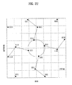
しかし、補強層信号配置が回転し、パワー分割比率が変化するとき、ユークリッド距離プロファイルは変化可能である。これは、図21の本来のグレーマッピングが、例えば、常に選択的なものではないことを意味する。この場合、それぞれのユークリッド距離ファイルの例に基づいてビット−ツー−シンボル再マッピングを行う必要がある。図22は、回転されたQPSK/QPSK階層変調のためのグレーマッピングを示した図である。 However, the Euclidean distance profile can change when the reinforcement layer signal arrangement rotates and the power split ratio changes. This means that the original gray mapping of FIG. 21, for example, is not always selective. In this case, it is necessary to perform bit-to-symbol remapping based on the example of each Euclidean distance file. FIG. 22 is a diagram illustrating gray mapping for rotated QPSK / QPSK hierarchical modulation.
信号配置のBER性能は、特にSNRが高いとき、最小のユークリッド距離を有するシンボル対によって調整される。したがって、最も近い2個の信号に対するコードが最小距離を有する最適のビット−ツー−シンボルマッピング規則を探すべきである。 The BER performance of the signal constellation is adjusted by the symbol pair with the smallest Euclidean distance, especially when the SNR is high. Therefore, the best bit-to-symbol mapping rule should be sought where the code for the two closest signals has the smallest distance.
一般的に、チャネルコーディングと一緒に行われる2次元信号でのグレーマッピングは、類似した同一の信号のためのBERを最小化するために選択的である。通常の階層信号配置のためのグレーマッピングは、図21に示されている。ここで、2個の最も近い信号のためのコードは、一つのビットのみで異なる。しかし、このような種類のユークリッド距離プロファイルは、階層変調で固定されないこともある。異なる回転角を有する16QAM/QPSK階層変調の最小のユークリッド距離の例は、図23に示されている。 In general, gray mapping on a two-dimensional signal performed along with channel coding is selective to minimize the BER for similar identical signals. Gray mapping for normal hierarchical signal placement is shown in FIG. Here, the codes for the two closest signals differ by only one bit. However, this type of Euclidean distance profile may not be fixed by hierarchical modulation. An example of the minimum Euclidean distance for 16QAM / QPSK hierarchical modulation with different rotation angles is shown in FIG.
図23は、補強されたQPSK/QPSK階層変調の一例を示した図である。図23を参照すると、基本層はQPSKに変調され、補強層は、回転されたQPSKに変調される。階層変調が適用されると、新しいQPSK/QPSK階層変調が、この図面に示すように得られる。 FIG. 23 is a diagram illustrating an example of reinforced QPSK / QPSK hierarchical modulation. Referring to FIG. 23, the base layer is modulated to QPSK, and the reinforcing layer is modulated to rotated QPSK. When hierarchical modulation is applied, a new QPSK / QPSK hierarchical modulation is obtained as shown in this figure.
また、2層の階層変調で電力分割比率が増加するとき、層間ユークリッド距離が最も小さくなる。これは、補強層が回転されるときに発生する。ユークリッド距離プロファイルが階層変調で変わるとき、BERを最小化するために、図24及び図25に示すように、ビット−ツー−シンボルマッピングが再び行われる。 In addition, when the power division ratio is increased by two layers of hierarchical modulation, the interlayer Euclidean distance becomes the smallest. This occurs when the reinforcing layer is rotated. When the Euclidean distance profile changes with hierarchical modulation, bit-to-symbol mapping is performed again as shown in FIGS. 24 and 25 to minimize the BER.
図24は、新しいQPSK/QPSK階層変調の一例を示した図で、図25は、新しいQPSK/QPSK階層変調の他の例を示した図である。 FIG. 24 is a diagram illustrating an example of a new QPSK / QPSK hierarchical modulation, and FIG. 25 is a diagram illustrating another example of a new QPSK / QPSK hierarchical modulation.
上述したように、新しいビット−ツー−シンボル発生構造が導入される。従来の構造によると、シンボルマッピングモード選択が用いられていなかった。図26は、新しいビット−ツー−シンボルブロックを示した図である。ここで、ビット−ツー−シンボルマッピングが行われるとき、シンボルマッピングモードが選択される。特に、新しいシンボルマッピングモード選択ブロックが、使用された階層変調及びチャネルコーディングの信号配置に基づいてビット−ツー−シンボルマッピング規則を制御及び/または選択するように追加される。 As mentioned above, a new bit-to-symbol generation structure is introduced. According to the conventional structure, symbol mapping mode selection has not been used. FIG. 26 shows a new bit-to-symbol block. Here, when bit-to-symbol mapping is performed, a symbol mapping mode is selected. In particular, a new symbol mapping mode selection block is added to control and / or select bit-to-symbol mapping rules based on the hierarchical modulation and channel coding signal constellation used.
本発明は、本発明の範囲を逸脱しない限度内で多様に変更可能である。本発明は、添付された特許請求の範囲及びその同等物の範囲内で提供される変形をカバーする。 The present invention can be variously modified without departing from the scope of the present invention. The present invention covers variations provided within the scope of the appended claims and their equivalents.
Claims (6)
複数のシンボルを第1のレイヤ信号配置および第2のレイヤ信号配置に割り当てることであって、該第1のレイヤ信号配置は、ベースレイヤ信号を参照し、該第2のレイヤ信号配置は、強化レイヤ信号を参照する、ことと、
該第1のレイヤ信号配置および該第2のレイヤ信号配置の該複数のシンボルを変調することであって、該第2のレイヤ信号配置の該複数のシンボルは、受信器から受信された第2の回転角に関する情報に基づいて決定された第1の回転角だけ回転される、ことと、
該変調されたシンボルを該受信器に伝送することと
を含み、該複数のシンボルを変調するために使用される構成情報が、制御メッセージにおいて該受信器に提供され、該構成情報は、該第1の回転角に関する情報が該制御メッセージ内に含まれるか否かを示すインジケータを含み、該インジケータが、該第1の回転角に関する情報が該制御メッセージ内に含まれることを示す場合には該第1の回転角に関する情報をさらに含む、方法。A method for transmitting two or more signals in a wireless communication system, the method comprising:
Assigning a plurality of symbols to a first layer signal constellation and a second layer signal constellation, wherein the first layer signal constellation refers to a base layer signal and the second layer signal constellation is enhanced Referencing the layer signal,
Modulating the plurality of symbols of the first layer signal constellation and the second layer signal constellation, wherein the plurality of symbols of the second layer signal constellation are received from a receiver only the first rotation angle determined based on information on the rotation angle of the rotation, and that,
And a transmitting the symbols said modulated to the receiver, configuration information used to modulate the symbols of said plurality of, are provided to the receiver in the control message, said configuration information, said includes an indicator information related to the rotation angle of 1 indicates whether or not contained in the control message, the indicator, the is to indicate that the information relating to the first rotation angle is included in the control message The method further comprising information regarding the first rotation angle.
前記第1のレイヤ信号配置および前記第2のレイヤ信号配置がどのように変調され、スケール化されるかを示すために使用される変調セグメントを備える、請求項1に記載の方法。The control message is
It said first layer signal constellation and the second layer signal constellation is how modulated, comprising a modulation segment used to indicate the scaled method of claim 1.
複数のシンボルを第1のレイヤ信号配置および第2のレイヤ信号配置に割り当てる第1の論理ユニットであって、該第1のレイヤ信号配置は、ベースレイヤ信号を参照し、該第2のレイヤ信号配置は、強化レイヤ信号を参照する、第1の論理ユニットと、
該第1のレイヤ信号配置および該第2のレイヤ信号配置の該複数のシンボルを変調する第2の論理ユニットであって、該第2のレイヤ信号配置の該複数のシンボルは、受信器から受信された第2の回転角に関する情報に基づいて決定された第1の回転角だけ回転される、第2の論理ユニットと、
該変調されたシンボルを該受信器に伝送する第3の論理ユニットと
を含み、該複数のシンボルを変調するために使用される構成情報が、制御メッセージにおいて該受信器に提供され、該構成情報は、該第1の回転角に関する情報が該制御メッセージ内に含まれるか否かを示すインジケータを含み、該インジケータが、該第1の回転角に関する情報が該制御メッセージ内に含まれることを示す場合には該第1の回転角に関する情報をさらに含む、装置。An apparatus for transmitting two or more signals in a wireless communication system, the apparatus comprising:
A first logical unit that assigns a plurality of symbols to a first layer signal constellation and a second layer signal constellation, wherein the first layer signal constellation refers to a base layer signal and the second layer signal constellation The placement includes a first logical unit that references the enhancement layer signal;
A second logical unit that modulates the plurality of symbols of the first layer signal constellation and the second layer signal constellation, wherein the plurality of symbols of the second layer signal constellation are received from a receiver is rotated by the first rotation angle determined based on the information about the second rotation angle is, the second logical unit,
A third logical unit for transmitting the modulated symbols to the receiver, and configuration information used to modulate the plurality of symbols is provided to the receiver in a control message, the configuration information includes an indicator indicating whether or not the information related to the rotation angle of the first is included in the control message, indicating that said indicator, information relating to the first rotation angle is included in the control message case further includes information about the first rotation angle the apparatus.
Applications Claiming Priority (9)
| Application Number | Priority Date | Filing Date | Title |
|---|---|---|---|
| US80168906P | 2006-05-19 | 2006-05-19 | |
| US60/801,689 | 2006-05-19 | ||
| US89683107P | 2007-03-23 | 2007-03-23 | |
| US60/896,831 | 2007-03-23 | ||
| US90990607P | 2007-04-03 | 2007-04-03 | |
| US60/909,906 | 2007-04-03 | ||
| US91042007P | 2007-04-05 | 2007-04-05 | |
| US60/910,420 | 2007-04-05 | ||
| PCT/KR2007/002461 WO2007136211A2 (en) | 2006-05-19 | 2007-05-21 | A method of utilizing and manipulating wireless resources for efficient and effective wireless communication |
Publications (3)
| Publication Number | Publication Date |
|---|---|
| JP2009538031A JP2009538031A (en) | 2009-10-29 |
| JP2009538031A5 JP2009538031A5 (en) | 2011-08-11 |
| JP4940297B2 true JP4940297B2 (en) | 2012-05-30 |
Family
ID=38723711
Family Applications (1)
| Application Number | Title | Priority Date | Filing Date |
|---|---|---|---|
| JP2009510896A Expired - Fee Related JP4940297B2 (en) | 2006-05-19 | 2007-05-21 | Method of operating with radio resources for efficient and effective radio communication |
Country Status (9)
| Country | Link |
|---|---|
| US (1) | US20070268977A1 (en) |
| EP (1) | EP2018750B1 (en) |
| JP (1) | JP4940297B2 (en) |
| KR (1) | KR100964703B1 (en) |
| CN (1) | CN101558620B (en) |
| AU (1) | AU2007252363B2 (en) |
| CA (1) | CA2637758C (en) |
| TW (1) | TWI470979B (en) |
| WO (1) | WO2007136211A2 (en) |
Families Citing this family (27)
| Publication number | Priority date | Publication date | Assignee | Title |
|---|---|---|---|---|
| KR101422014B1 (en) | 2007-05-10 | 2014-07-23 | 엘지전자 주식회사 | Method For Generating Long Code By Repeating Basic Code, And Method For Transmitting Control Information Using The Same |
| CN101374033B (en) * | 2007-08-23 | 2013-03-27 | 株式会社Ntt都科摩 | Method and apparatus for processing data of multi-input multi-output system |
| CN101494629A (en) * | 2008-01-24 | 2009-07-29 | 华为技术有限公司 | Method and apparatus for obtaining symbol mapping diversity, generating star map and modulation |
| WO2009096842A1 (en) * | 2008-01-30 | 2009-08-06 | Telefonaktiebolaget L M Ericsson (Publ) | A method of data modulation adapted to selected modulation rotational angle |
| EP2235896B1 (en) * | 2008-01-30 | 2013-03-27 | Telefonaktiebolaget LM Ericsson (publ) | A receiver for muros adapted to estimate symbol constellation using training sequences from two sub-channels |
| WO2009096843A1 (en) * | 2008-01-30 | 2009-08-06 | Telefonaktiebolaget L M Ericsson (Publ) | Report mechanism in a radio system reusing one time-slot |
| JP5579622B2 (en) * | 2008-01-30 | 2014-08-27 | テレフオンアクチーボラゲット エル エム エリクソン(パブル) | Time slot sharing using non-uniform QPSK modulation |
| JP5241313B2 (en) * | 2008-05-12 | 2013-07-17 | 株式会社エヌ・ティ・ティ・ドコモ | Wireless communication apparatus and wireless communication method |
| CN101640940A (en) * | 2008-07-30 | 2010-02-03 | 华为技术有限公司 | Method and base station for indicating modulation encoding scheme during multi-user joint mapping |
| US8675754B1 (en) * | 2009-08-19 | 2014-03-18 | Qualcomm Incorporated | Hybrid modulation schemes used in data communication |
| KR101799108B1 (en) * | 2010-06-18 | 2017-11-17 | 한국전자통신연구원 | System for transmitting broadcasting data |
| US8971432B2 (en) | 2011-04-19 | 2015-03-03 | Panasonic Intellectual Property Corporation Of America | Signal generating method and signal generating device |
| CN103248592B (en) * | 2012-02-08 | 2018-04-27 | 株式会社Ntt都科摩 | Multi-user data transmission method, system and relay node based on hierarchical modulation |
| US9203673B2 (en) * | 2012-05-13 | 2015-12-01 | Broadcom Corporation | Multi-channel support within single user, multiple user, multiple access, and/or MIMO wireless communications |
| EP2675072A1 (en) * | 2012-06-15 | 2013-12-18 | Fraunhofer-Gesellschaft zur Förderung der angewandten Forschung e.V. | Method for spreading a plurality of data symbols onto subcarriers of a carrier signal |
| WO2014030501A1 (en) * | 2012-08-23 | 2014-02-27 | 三菱電機株式会社 | Communication system, transmission device, receiving device, and digital transmission method |
| US9509379B2 (en) * | 2013-06-17 | 2016-11-29 | Huawei Technologies Co., Ltd. | System and method for designing and using multidimensional constellations |
| US11271703B2 (en) * | 2014-05-02 | 2022-03-08 | Qualcomm Incorporated | Techniques for improving control channel capacity |
| US9942013B2 (en) | 2014-05-07 | 2018-04-10 | Qualcomm Incorporated | Non-orthogonal multiple access and interference cancellation |
| US10523383B2 (en) | 2014-08-15 | 2019-12-31 | Huawei Technologies Co., Ltd. | System and method for generating waveforms and utilization thereof |
| CN105634654B (en) * | 2014-10-27 | 2019-12-17 | 中兴通讯股份有限公司 | Superposition coding and demodulation method and device for multi-user information transmission |
| CN106160971B (en) * | 2015-04-07 | 2019-05-28 | 电信科学技术研究院 | A kind of method and apparatus that data are transmitted, receive signal detection |
| CN106302299B (en) * | 2015-05-20 | 2020-06-05 | 中兴通讯股份有限公司 | Multi-user access method and device |
| CN107276954B (en) * | 2016-04-08 | 2020-04-14 | 中国移动通信有限公司研究院 | Baseband signal processing method and device |
| EP3293680A1 (en) * | 2016-09-12 | 2018-03-14 | Authentic Vision GmbH | Sheet-like product and method for authenticating a security tag |
| CN107204832B (en) * | 2017-06-19 | 2020-08-25 | 电子科技大学 | SCMA codebook design method, SCMA encoder and SCMA system |
| EP4246906A3 (en) * | 2018-10-12 | 2024-01-03 | Ciena Corporation | Probabilistic constellation shaping of multi-dimensional symbols for improved tolerance to nonlinear impairments |
Family Cites Families (20)
| Publication number | Priority date | Publication date | Assignee | Title |
|---|---|---|---|---|
| DE69334247D1 (en) * | 1992-09-25 | 2008-12-24 | Matsushita Electric Ind Co Ltd | Multi-carrier transmission with variable symbol part and guard interval |
| EP0616454A1 (en) * | 1993-03-17 | 1994-09-21 | Laboratoires D'electronique Philips S.A.S. | Multi-resolution digital transmission system |
| JP2768354B2 (en) * | 1996-07-15 | 1998-06-25 | 日本電気株式会社 | Relay system, transmission device and relay device used for the same |
| JP3115255B2 (en) * | 1997-06-13 | 2000-12-04 | 株式会社ケンウッド | Absolute phase shift circuit |
| US6914934B1 (en) * | 1999-09-03 | 2005-07-05 | Agere Systems Inc. | Multiplier-free methods and apparatus for signal processing in a digital communication system |
| US7088671B1 (en) * | 1999-11-24 | 2006-08-08 | Peter Monsen | Multiple access technique for downlink multibeam digital radio systems |
| JP3607643B2 (en) | 2001-07-13 | 2005-01-05 | 松下電器産業株式会社 | Multicarrier transmission apparatus, multicarrier reception apparatus, and multicarrier radio communication method |
| JP4119696B2 (en) * | 2001-08-10 | 2008-07-16 | 松下電器産業株式会社 | Transmitting apparatus, receiving apparatus, and wireless communication method |
| JP2004128988A (en) * | 2002-10-03 | 2004-04-22 | Ntt Docomo Inc | Communication system, receiver and transmitter and communicating method |
| US7412008B2 (en) * | 2003-06-30 | 2008-08-12 | Freescale Semiconductor, Inc. | Programmable phase mapping and phase rotation modulator and method |
| JP4445467B2 (en) * | 2003-07-02 | 2010-04-07 | パナソニック株式会社 | Communication apparatus and communication method |
| US6999467B2 (en) * | 2003-07-28 | 2006-02-14 | Motorola, Inc. | Method and apparatus for transmission and reception within an OFDM communication system |
| BRPI0413594A (en) * | 2003-08-20 | 2006-10-17 | Thomson Licensing | Method and apparatus for hierarchical modulation using a radial constellation |
| JP2007503734A (en) * | 2003-08-22 | 2007-02-22 | コーニンクレッカ フィリップス エレクトロニクス エヌ ヴィ | Backward compatible multi-carrier transmission system |
| KR100757963B1 (en) * | 2003-12-24 | 2007-09-11 | 삼성전자주식회사 | A Method And Apparatus For CODING |
| US20050143085A1 (en) * | 2003-12-30 | 2005-06-30 | Hao Bi | Broadcast/multicast services in wireless communications networks and methods |
| EP1610480A1 (en) | 2004-06-25 | 2005-12-28 | Mitsubishi Electric Information Technology Center Europe B.V. | Device and method of dynamically assigning subgroups of spreading sequences |
| US8023589B2 (en) * | 2004-08-09 | 2011-09-20 | Texas Instruments Incorporated | Wireless MIMO transmitter with antenna and tone precoding blocks |
| US20060198454A1 (en) * | 2005-03-02 | 2006-09-07 | Qualcomm Incorporated | Adaptive channel estimation thresholds in a layered modulation system |
| US7725799B2 (en) * | 2005-03-31 | 2010-05-25 | Qualcomm Incorporated | Power savings in hierarchically coded modulation |
-
2007
- 2007-05-21 CN CN200780014494.7A patent/CN101558620B/en not_active Expired - Fee Related
- 2007-05-21 CA CA2637758A patent/CA2637758C/en not_active Expired - Fee Related
- 2007-05-21 JP JP2009510896A patent/JP4940297B2/en not_active Expired - Fee Related
- 2007-05-21 EP EP07746609.2A patent/EP2018750B1/en not_active Not-in-force
- 2007-05-21 KR KR1020087029832A patent/KR100964703B1/en not_active IP Right Cessation
- 2007-05-21 TW TW96118109A patent/TWI470979B/en not_active IP Right Cessation
- 2007-05-21 WO PCT/KR2007/002461 patent/WO2007136211A2/en active Application Filing
- 2007-05-21 AU AU2007252363A patent/AU2007252363B2/en not_active Ceased
- 2007-05-21 US US11/751,512 patent/US20070268977A1/en not_active Abandoned
Also Published As
| Publication number | Publication date |
|---|---|
| US20070268977A1 (en) | 2007-11-22 |
| CA2637758C (en) | 2011-09-20 |
| TW200810455A (en) | 2008-02-16 |
| CA2637758A1 (en) | 2007-11-29 |
| CN101558620B (en) | 2014-11-12 |
| KR20090009306A (en) | 2009-01-22 |
| EP2018750B1 (en) | 2016-03-09 |
| AU2007252363B2 (en) | 2009-10-01 |
| EP2018750A4 (en) | 2014-03-12 |
| WO2007136211A3 (en) | 2009-06-11 |
| EP2018750A2 (en) | 2009-01-28 |
| TWI470979B (en) | 2015-01-21 |
| CN101558620A (en) | 2009-10-14 |
| JP2009538031A (en) | 2009-10-29 |
| AU2007252363A1 (en) | 2007-11-29 |
| KR100964703B1 (en) | 2010-06-21 |
| WO2007136211A2 (en) | 2007-11-29 |
Similar Documents
| Publication | Publication Date | Title |
|---|---|---|
| JP4940297B2 (en) | Method of operating with radio resources for efficient and effective radio communication | |
| US7826548B2 (en) | Resource management in a wireless communication network | |
| US11349531B2 (en) | Pilot scheme for a MIMO communication system | |
| JP4430714B2 (en) | Method and apparatus for uplink high-speed feedback information transmission in orthogonal frequency division multiple access (OFDMA) communication system | |
| JP4249750B2 (en) | Apparatus and method for transmitting high-speed feedback information in a wireless communication system | |
| US8520499B2 (en) | Method, apparatus, and system for transmitting and receiving information of an uncoded channel in an orthogonal frequency division multiplexing system | |
| JP3963737B2 (en) | Multi-carrier signal generation method, radio transmission apparatus, and radio reception apparatus | |
| EP1832075A1 (en) | Communicating non-coherent detectable signal in broadband wireless access system | |
| US20030063685A1 (en) | Coding method in multicarrier transmission and encoder using the same | |
| KR20080111920A (en) | Method and apparatus for transmitting uplink control channel in mobile communication system | |
| JP4398985B2 (en) | Wireless transmission device | |
| Albogame | Enhanced MIMO and TCM-APSK in PTS-OFDMA Wireless System and its Application |
Legal Events
| Date | Code | Title | Description |
|---|---|---|---|
| A521 | Request for written amendment filed |
Free format text: JAPANESE INTERMEDIATE CODE: A523 Effective date: 20110621 |
|
| A977 | Report on retrieval |
Free format text: JAPANESE INTERMEDIATE CODE: A971007 Effective date: 20110930 |
|
| A131 | Notification of reasons for refusal |
Free format text: JAPANESE INTERMEDIATE CODE: A131 Effective date: 20111024 |
|
| A521 | Request for written amendment filed |
Free format text: JAPANESE INTERMEDIATE CODE: A523 Effective date: 20111202 |
|
| TRDD | Decision of grant or rejection written | ||
| A01 | Written decision to grant a patent or to grant a registration (utility model) |
Free format text: JAPANESE INTERMEDIATE CODE: A01 Effective date: 20120220 |
|
| A01 | Written decision to grant a patent or to grant a registration (utility model) |
Free format text: JAPANESE INTERMEDIATE CODE: A01 |
|
| A61 | First payment of annual fees (during grant procedure) |
Free format text: JAPANESE INTERMEDIATE CODE: A61 Effective date: 20120227 |
|
| FPAY | Renewal fee payment (event date is renewal date of database) |
Free format text: PAYMENT UNTIL: 20150302 Year of fee payment: 3 |
|
| R150 | Certificate of patent or registration of utility model |
Free format text: JAPANESE INTERMEDIATE CODE: R150 |
|
| R250 | Receipt of annual fees |
Free format text: JAPANESE INTERMEDIATE CODE: R250 |
|
| R250 | Receipt of annual fees |
Free format text: JAPANESE INTERMEDIATE CODE: R250 |
|
| R250 | Receipt of annual fees |
Free format text: JAPANESE INTERMEDIATE CODE: R250 |
|
| LAPS | Cancellation because of no payment of annual fees |