JP4939656B2 - FSK receiver for hearing aid and method for processing FSK signal - Google Patents
FSK receiver for hearing aid and method for processing FSK signal Download PDFInfo
- Publication number
- JP4939656B2 JP4939656B2 JP2010532433A JP2010532433A JP4939656B2 JP 4939656 B2 JP4939656 B2 JP 4939656B2 JP 2010532433 A JP2010532433 A JP 2010532433A JP 2010532433 A JP2010532433 A JP 2010532433A JP 4939656 B2 JP4939656 B2 JP 4939656B2
- Authority
- JP
- Japan
- Prior art keywords
- signal
- stage
- fsk
- output
- receiver
- Prior art date
- Legal status (The legal status is an assumption and is not a legal conclusion. Google has not performed a legal analysis and makes no representation as to the accuracy of the status listed.)
- Expired - Fee Related
Links
Images


Classifications
-
- H—ELECTRICITY
- H04—ELECTRIC COMMUNICATION TECHNIQUE
- H04L—TRANSMISSION OF DIGITAL INFORMATION, e.g. TELEGRAPHIC COMMUNICATION
- H04L27/00—Modulated-carrier systems
- H04L27/10—Frequency-modulated carrier systems, i.e. using frequency-shift keying
- H04L27/14—Demodulator circuits; Receiver circuits
-
- H—ELECTRICITY
- H04—ELECTRIC COMMUNICATION TECHNIQUE
- H04R—LOUDSPEAKERS, MICROPHONES, GRAMOPHONE PICK-UPS OR LIKE ACOUSTIC ELECTROMECHANICAL TRANSDUCERS; DEAF-AID SETS; PUBLIC ADDRESS SYSTEMS
- H04R25/00—Deaf-aid sets, i.e. electro-acoustic or electro-mechanical hearing aids; Electric tinnitus maskers providing an auditory perception
- H04R25/55—Deaf-aid sets, i.e. electro-acoustic or electro-mechanical hearing aids; Electric tinnitus maskers providing an auditory perception using an external connection, either wireless or wired
- H04R25/554—Deaf-aid sets, i.e. electro-acoustic or electro-mechanical hearing aids; Electric tinnitus maskers providing an auditory perception using an external connection, either wireless or wired using a wireless connection, e.g. between microphone and amplifier or using Tcoils
-
- H—ELECTRICITY
- H04—ELECTRIC COMMUNICATION TECHNIQUE
- H04R—LOUDSPEAKERS, MICROPHONES, GRAMOPHONE PICK-UPS OR LIKE ACOUSTIC ELECTROMECHANICAL TRANSDUCERS; DEAF-AID SETS; PUBLIC ADDRESS SYSTEMS
- H04R2225/00—Details of deaf aids covered by H04R25/00, not provided for in any of its subgroups
- H04R2225/51—Aspects of antennas or their circuitry in or for hearing aids
-
- H—ELECTRICITY
- H04—ELECTRIC COMMUNICATION TECHNIQUE
- H04R—LOUDSPEAKERS, MICROPHONES, GRAMOPHONE PICK-UPS OR LIKE ACOUSTIC ELECTROMECHANICAL TRANSDUCERS; DEAF-AID SETS; PUBLIC ADDRESS SYSTEMS
- H04R2225/00—Details of deaf aids covered by H04R25/00, not provided for in any of its subgroups
- H04R2225/55—Communication between hearing aids and external devices via a network for data exchange
Abstract
Description
本願は補聴器に関する。より詳細にはワイヤレス受信機を備えた補聴器に関する。さらに詳細にはこの発明は周波数シフト・キーイング(周波数偏移変調)(frequency shift keying)(FSK)受信機を備えた補聴器に関する。 The present application relates to hearing aids. More particularly, it relates to a hearing aid equipped with a wireless receiver. More particularly, this invention relates to a hearing aid with a frequency shift keying (FSK) receiver.
補聴器における共通の信号源は,補聴器の近傍において発生する音響信号(acoustic sound signals)をピックアップする一または複数のマイクロフォンである。補聴器において共通する他の信号源は,テレコイル受信機である。この受信機は,通常,受信機を備える補聴器の周囲のテレコイル送信機からの電磁ベースバンド(すなわち,非変調)音周波数信号(electromagnetic base band (i.e. unmodulated) audio frequency signals)をピックアップするように構成された小さなコイルとして実装される。 A common signal source in a hearing aid is one or more microphones that pick up acoustic sound signals generated in the vicinity of the hearing aid. Another signal source common to hearing aids is a telecoil receiver. This receiver is typically configured to pick up electromagnetic baseband (ie unmodulated) audio frequency signals from a telecoil transmitter around the hearing aid equipped with the receiver. Mounted as a small coil.
補聴器回路要素(hearing aid circuitry )による増幅,調整および再生を目的とする高度な機能のために,従来技術において,補聴器は通常複数の信号源に適応するように設計されている。 Due to the advanced functions aimed at amplification, adjustment and reproduction by hearing aid circuitry, in the prior art, hearing aids are usually designed to accommodate multiple signal sources.
耳掛け形(behind the ear)(BTE)補聴器の中には,FM受信機,ブルートゥース(商標)受信機,ケーブルなどの外部装置(external equipment)を補聴器回路要素に接続するための接続手段を備えたものがある。このような外部装置は様々な態様で補聴器と通信可能であり,たとえばケーブル接続は通常補聴器をプログラミングするために設けられ,FM受信機はワイヤレスFM送信機付のマイクロフォンを身につけた話者がいる公の場所において用いるときに接続することができ,ブルートゥース(商標)受信機は携帯電話などからのオーディオ信号をストリーミングするために用いることができる。 Some behind the ear (BTE) hearing aids have connecting means for connecting external equipment such as FM receivers, Bluetooth ™ receivers, cables, etc. to the hearing aid circuitry. There is something. Such an external device can communicate with the hearing aid in various ways, for example, a cable connection is usually provided for programming the hearing aid, and the FM receiver has a speaker wearing a microphone with a wireless FM transmitter. It can be connected when used in public places and a Bluetooth ™ receiver can be used to stream audio signals from mobile phones and the like.
また,最新の補聴器の中には内部ワイヤレス受信機を備えたものもある。このタイプのワイヤレス受信機のほとんどは電力を補聴器電池から直接に引出す。従来知られているワイヤレス受信機を長時間使用すると補聴器電池は短時間で消耗してしまい,頻繁な電池交換の必要性や補聴器の動作のコストが増す。別体の電池を備える統合電力サプライ(integral power supplies )を有するタイプの受信機は,重量,サイズ,受信機の複雑性が増す。したがって,より電力効率のよいワイヤレス受信機が補聴器ユーザに多大な利益をもたらす。 Some modern hearing aids have an internal wireless receiver. Most of this type of wireless receiver draws power directly from the hearing aid battery. When a conventionally known wireless receiver is used for a long time, the hearing aid battery is consumed in a short time, and the necessity of frequent battery replacement and the cost of operation of the hearing aid increase. A type of receiver with integrated power supplies with separate batteries adds weight, size, and receiver complexity. Therefore, a more power efficient wireless receiver provides significant benefits to hearing aid users.
電力効率は,たとえば,受信機回路要素の全体の電力消費を低減することによって高めることができる。しかしながら,これは,信号品質の低下につながる受信機の雑音パフォーマンスを損なうことなく,行われるべきである。当業者に知られている,送信信号がディジタル・フォーマットされるFSK送信機/受信機の構成が,一般に推奨されている。 Power efficiency can be increased, for example, by reducing the overall power consumption of the receiver circuit elements. However, this should be done without compromising the noise performance of the receiver which leads to signal quality degradation. An FSK transmitter / receiver configuration known to those skilled in the art in which the transmitted signal is digitally formatted is generally recommended.
FSK信号はいくつかのやり方で復調することができ,それぞれ異なる利点,トポロジーおよび複雑性を持つ。復調器はいくつかのカテゴリに細分され,FM〜AM復調器タイプ(たとえば,スロープ(Slope),フォスター−シーリー(Foster:Seeley )およびレイシオ(Ratio)),PLL復調器,ゼロクロス復調器,および直交復調器(Quadrature demodulators)などがある。 The FSK signal can be demodulated in several ways, each with different advantages, topologies and complexity. Demodulators are subdivided into several categories, FM to AM demodulator types (eg, Slope, Foster: Seeley and Ratio), PLL demodulator, zero-cross demodulator, and orthogonal There are quadrature demodulators.
従来技術において知られている直交復調器のタイプの一つは,ローカル・オシレータ(local oscillator)と,同相分岐(in-phase branch)および直交(直角位相)分岐(quadrature branch)をそれぞれ表す2つの信号分岐とを備え,受信信号を同相(I)成分と直交(Q)成分に分割する(split)。直交信号(バイナリ)において,一の成分にバイナリ0(binary zero)が割当てられ,他の成分にバイナリ1(binary one)が割り当てられる。IおよびQの2つの信号成分は相互に排他的であるので,送信機が動作するとき,1と0とからなるディジタルビットストリーム(digital bitstream )が生成される。両方の分岐がCPUに接続され,ここで復調処理が完結する。一般に,それぞれの分岐は,乗算器(multiplier),フィルタ(filter)および判定装置(decision device )を備える。同相分岐における乗算器はローカル・オシレータに直接に接続され,他方,直交分岐における乗算器はローカル・オシレータの90°位相シフト・バージョン(態様)(90°phase-shifted version )に接続される。周波数シフト・キーイングされた信号中の情報がその後デコードされて,所望の目的にしたがって利用される。
One type of quadrature demodulator known in the prior art is a local oscillator, two of which represent an in-phase branch and a quadrature branch, respectively. Signal branching, and splits the received signal into in-phase (I) and quadrature (Q) components. In the quadrature signal (binary),
このようなFSK復調器は,たとえば,バルケ(Burke )名義のUS4 987 374に記載されている。この復調器は第1および第2分岐に与えられる一つのローカル・オシレータを備え,各分岐はミキサおよび検知段を含む。第1の分岐におけるミキサは入力信号をローカル・オシレータからの直接信号に混合し(mix ),第2の分岐におけるミキサは入力信号をローカル・オシレータからの信号の90°位相シフト・バージョン(90° phase shifted version)に混合する。 Such an FSK demodulator is described, for example, in US Pat. No. 4,987,374 in the name of Burke. The demodulator comprises one local oscillator fed to the first and second branches, each branch including a mixer and a detection stage. The mixer in the first branch mixes the input signal with the direct signal from the local oscillator (mix), and the mixer in the second branch mixes the input signal with the 90 ° phase shifted version (90 ° of the signal from the local oscillator). mix into phase shifted version).
従来技術のFSK受信機はほとんどの用途において満足のいく動作を行う。しかしながら,補聴器中のように利用可能な電力が非常に少ない(only small)と,有効伝達範囲(effective transmission range)が非常に短くなり,たとえば信号中に存在するノイズを原因とする受信エラーによって受信信号の品質がかなり損なれることがある。 Prior art FSK receivers perform satisfactorily for most applications. However, if the available power is very small (only small) as in a hearing aid, the effective transmission range becomes very short, for example due to reception errors caused by noise present in the signal. Signal quality can be significantly impaired.
したがって,電力消費を大幅に増大させることなく,FSK受信機の雑音安定度(雑音耐性)(noise immunity)を改善する目的のための,より信頼のある信号検出の手段が望まれている。 Therefore, a more reliable means of signal detection is desired for the purpose of improving the noise immunity of FSK receivers without significantly increasing power consumption.
この発明による補聴器中における利用に適するワイヤレスFSK受信機は,請求項1に表わされた特徴を有している。
A wireless FSK receiver suitable for use in a hearing aid according to the invention has the features set forth in
二つから三つ,四つ,五つまたはそれ以上の分岐に復調器の分岐数を増やすことによって,全体のビット分解能,すなわち,この発明によるFSK受信機の,データビット単位に送られる離散シンボル数(the number of discrete symbols sent per data bit)がかなり増加する。受信機に複雑性が付加されるものの,近年のマイクロ電子工学の技術を利用することで,より多くの復調器分岐の追加から生じる増加電力消費量は許容できることが確認されている。したがって,FSK受信機設計に対する,より有効でしかも電力効率のよいアプローチが達成される。5〜10の復調器分岐から構成されるワイヤレスFSK受信機は,雑音安定度(noise immunity),回路複雑性(circuit complexity)および全体の受信機電力消費(total receiver power consumption)の間の最も最適なバランスをもたらすと考えられる。 By increasing the number of demodulator branches from two to three, four, five or more branches, the overall bit resolution, i.e. the discrete symbols sent in units of data bits of the FSK receiver according to the invention. The number of discrete symbols sent per data bit increases considerably. Despite the added complexity of the receiver, it has been confirmed that the increased power consumption resulting from the addition of more demodulator branches can be tolerated using recent microelectronic technology. Thus, a more effective and power efficient approach to FSK receiver design is achieved. A wireless FSK receiver consisting of 5-10 demodulator branches is the most optimal between noise immunity, circuit complexity and total receiver power consumption. It is thought to bring about a good balance.
第2の態様において,この発明は請求項7に規定されるワイヤレスFSK受信機を提供する。 In a second aspect, the present invention provides a wireless FSK receiver as defined in claim 7.
第3の態様において,この発明は請求項9に規定される方法を提供する。 In a third aspect, the present invention provides a method as defined in claim 9.
さらなる特徴および利点が従属請求項から明らかにされる。 Further features and advantages are revealed from the dependent claims.
以下,図面を参照してこの発明をさらに詳細に説明する。 Hereinafter, the present invention will be described in more detail with reference to the drawings.
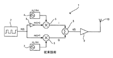
図1は,従来技術による周波数シフト・キーイング(FSK)送信機1を示す。FSK送信機1は,シリアル・ビット・ストリーム生成器2,インバータ3,第1のミキサまたは乗算器5,第1のローカル・オシレータ(発振器)4,第2のミキサまたは乗算器6,第2のローカル・オシレータ7,加算ノード8,出力段(ステージ)9,および送信アンテナ10を備えている。データ信号m(t)がシリアル・ビット・ストリーム生成器2によって生成されて2つの分岐に分割(split )される。下側の分岐における信号は第2のミキサ6において第2のローカル・オシレータ7からの信号と混合(mix )され,上側の分岐における信号はインバータ3によって反転されて(inverted),第1のミキサ5において第1のローカル・オシレータ4からの信号と混合される。上側の分岐にインバータ3が存在していることに起因して,常にミキサ5,6の一つのみが出力信号を生成する。
FIG. 1 shows a prior art frequency shift keying (FSK)
ローカル・オシレータ4,7からの信号はそれぞれ次のように記述することができる。
The signals from the

復調器1の2つの出力分岐からの信号は加算ノード8において加算され,その結果次式のFSK信号s(t)が得られる。
Signals from the two output branches of the
![]()
![]()
FSK信号s(t)は,送信アンテナ10を通じた無線送信のために出力段9によって増幅される。このように,FSK送信機は,m(t)が「0」であるかまたは「1」であるかに依存して,ローカル・オシレータ4,7によって決定される2つの周波数のうちの一つを出力する。
The FSK signal s (t) is amplified by the output stage 9 for wireless transmission through the transmit
図2は,図1に示すFSK送信機1によって生成されるFSK信号の周波数スペクトルの一部を示している。この信号(signals)は,fc+Δfおよびfc−Δfの近傍(around )に存在する。スペクトル成分は,異なる変調インデックス値(different modulation index values)およびm(t)の異なるスペクトル成分(different spectral content )によって異なるものになる。
FIG. 2 shows a part of the frequency spectrum of the FSK signal generated by the
図3は,図1に示すFSK送信機によって生成されたワイヤレスFSK信号を受信して復号するように構成されている,従来技術のワイヤレスFSK受信機11を概略的に示すブロック図である。ワイヤレスFSK受信機11の入力段(ステージ)は,受信アンテナ12,増幅器13,およびリミッタ14を備えている。受信信号の検出のために,FSK受信機11はまた,第1のローカル・オシレータ15a,第1のミキサ16a,第1のローパス・フィルタ17a,第1のリミッタ18aを含む第1の位相検出段と,第2のローカル・オシレータ15b,第2のミキサ16b,第2のローパス・フィルタ17b,第2のリミッタ18bを含む第2の位相検出段と,CPUインターフェース19を備えている。
FIG. 3 is a block diagram that schematically illustrates a prior art
FSK信号が受信アンテナ12によってピックアップされ,増幅器13によって増幅され,かつリミッタ14によって調整される(conditioned )。リミッタ14の出力は2つの分岐に分けられて,第1のミキサ16aの入力および第2のミキサ16bの入力にそれぞれ与えられる。第1のミキサ16aでは,入力信号が第1のローカル・オシレータ15aからの出力信号に乗算される。その結果得られる出力信号が第1のローパス・フィルタ17aの入力に与えられ,第1のローパス・フィルタ17aからの出力信号が第1のリミッタ18aの入力に与えられる。
The FSK signal is picked up by the receiving
同様にして,第2のミキサ16bでは,入力信号が第2のローカル・オシレータ15bからの出力信号に乗算される。その結果得られる出力信号が第2のローパス・フィルタ17bの入力に与えられ,第2のローパス・フィルタ17bからの出力信号が第2のリミッタ18bの入力に与えられる。第1のリミッタ18aおよび第2のリミッタ18bから出力信号はさらなる処理のためにCPUインターフェース19の入力に与えられる。
Similarly, in the
図4は,図3に示す従来技術の受信機によって受信された信号のベクトルI(同相)およびベクトルQ(直交位相)を示すベクトル図である。ベクトルIおよびQは単位円上に図示され,互いに90°の位相差を持つ。横座標(0°)とベクトルIとの間の位相偏移(phase deviation )がΔω・tによって示されており,従来技術の受信機11の角度シンボル分解能(angular symbol resolution)を表す。
FIG. 4 is a vector diagram showing a vector I (in-phase) and a vector Q (quadrature phase) of the signal received by the prior art receiver shown in FIG. The vectors I and Q are illustrated on the unit circle and have a phase difference of 90 ° from each other. The phase deviation between the abscissa (0 °) and the vector I is indicated by Δω · t and represents the angular symbol resolution of the
この構成において,上記送信信号に存在する明確に検出可能な位相角の数と等しい(equal to the number of distinctly detectable phase angles in the transmitted signal)上記受信機中の位相検出段の数は2つであり,受信信号中に存在するノイズおよびEMC干渉が従来技術の受信機11の受信能力をかなり低めることがあり,その結果として情報が誤まって伝えられるか,歪められるか,または完全に失われることがある。送信電力が減少するにつれて雑音干渉に対する感受性(susceptibility)は大きくなる。受信品質は,いくつかのやり方,たとえば,送信機の電力を大きくする,伝送距離を短くする,または受信機の選択度を改良する(improving the receiver selectivity)ことで向上させることができる。
In this configuration, the number of phase detection stages in the receiver is two equal to the number of distinctly detectable phase angles in the transmitted signal. Yes, noise and EMC interference present in the received signal can significantly reduce the reception capability of the
現存する受信機との互換性を維持させるとすると,送信電力の増大は不可能であると考えられる。よりパワフルな送信機はまたかさばってしまい,たとえばポケットサイズのリモート・コントローラに組込むことが困難である。また,この場合,リモート・コントローラはポケットにしまわれて,そこから操作するのが便利であるので,送信距離も便宜的と考えられる(the transmission distance may also be a matter of convenience )。複雑性を増大させることなく受信機の感度(selectivity )を向上するのはかなり困難であり,受信機回路要素の電力消費はかなりなものになる。大幅に電力消費を増やすことなく向上した雑音余裕度(雑音耐性)を持つFSK受信機の提供が,この発明の目的である。 If the compatibility with existing receivers is maintained, it is considered impossible to increase the transmission power. More powerful transmitters are also bulky and difficult to integrate into, for example, a pocket-sized remote controller. In this case, since the remote controller is stored in a pocket and it is convenient to operate from there, the transmission distance may also be convenient (the transmission distance may also be a matter of convenience). Improving receiver selectivity without increasing complexity is quite difficult, and the power consumption of the receiver circuitry is significant. It is an object of the present invention to provide an FSK receiver with improved noise margin (noise immunity) without significantly increasing power consumption.
図5はこの発明の実施例によるワイヤレスFSK受信機の概略ブロック図である。ワイヤレスFSK受信機20はシングルエンドのFSK受信機(single ended FSK receiver)である。ワイヤレス受信機20の入力段は,受信アンテナ12,増幅器13およびリミッタ14を含み,従来技術のワイヤレス受信機11の入力段と同様である。受信信号の検出のために,FSK受信機20は5つの同一の復調器分岐(demodulator branches)を備え,各復調器は,ローカル・オシレータ15a,15b,15c,15d,15e,ミキサ16a,16b,16c,16d,16e,ローパス・フィルタ17a,17b,17c,17d,17e,およびリミッタ18a,18b,18c,18d,18eをそれぞれ備えている。
FIG. 5 is a schematic block diagram of a wireless FSK receiver according to an embodiment of the present invention. The
各リミッタ18a,18b,18c,18d,18eの出力はそれぞれ,重み(weights )x1,x2,x3,x4,x5 ,重みy1,y2,y3,y4,y5,第1の加算器Σxおよび第2の加算器Σy ,ならびにArctan2関数21を備えるルックアップ・テーブル・ブロック28の入力に接続されている。
Each
ワイヤレスFSK受信機20のリミッタ18a,18b,18c,18d,18eの各出力はルックアップ・テーブル28の入力に与えられ,xiおよびyi によって重付けられる2つの別々の分岐セットにそれぞれ分割される。重みx1,x2,x3,x4およびx5からの出力は第1の加算器Σxにおいて加算され,重みy1,y2,y3,y4およびy5からの出力は第2の加算器Σy において加算される。第1の加算器Σxおよび第2の加算器Σy からの出力はArctan2関数21の入力に与えられ,ルックアップ・テーブル28のArctan2関数21の出力は微分器(differentiator)22の入力に与えられる。Arctan2関数について,以下,さらに詳細に説明する。
The outputs of the
ここで用いられる2引数アークタンジェント関数(two argument arcus tangent function)は,アークタンジェント関数Arctan2(x,y)の変形(variant)であり,次のように定義される。 The two argument arc tangent function used here is a variant of the arc tangent function Arctan2 (x, y) and is defined as follows.
このように,単位円の右手サイドにおいてだけ定義される従来のアークタンジェント関数arctan(x,y)とは対照的に,アークタンジェント関数Arctan2(x,y)は単位円の全体(whole unit circle)において定義される。 Thus, in contrast to the conventional arctangent function arctan (x, y), which is defined only on the right hand side of the unit circle, the arctangent function Arctan2 (x, y) is the whole unit circle. Defined in
微分器22の出力はローパス・フィルタ23の入力に接続され,ローパス・フィルタ23の出力はコンパレータ27の入力に接続され,コンパレータ27の出力はクロック・データ・リカバリ・ブロック24の入力に接続されている。クロック・データ・リカバリ・ブロック24はクロック線Cおよびデータ線Dを介してバッファ25に接続されている。バッファ25の出力はシリアル・ペリフェラル・インターフェース26の入力に接続されている。
The output of the
アンテナ12は送信信号をピックアップし,増幅器13が受信信号を増幅してリミッタ14の入力に適する信号レベルにする。受信信号は,周波数変調され,周波数偏移変調された(a frequency modulated, frequency shift keyed)アナログビットストリームとして扱われる。受信信号はリミッタ14によって2レベルデジタルビットストリームに変換される。この信号は,次に説明する第1,第2,第3,第4および第5の復調器分岐(demodulator branches)に与えられる。
The
第1の復調器分岐15a,16a,17a,18aは,リミッタ14によって出力される信号の第1の部分(a first part of signal)を変換しかつ調整する(converts and conditions)。第1のローカル・オシレータ15aおよび第1のミキサ16aは受信信号をベースバンド信号に変換する。第1のミキサ16aは第1のローパス・フィルタ17aに送信信号の直接変換バージョン(direct converted version)を出力し,第1のフィルタ17aの出力からの信号は,第1分岐15a,16a,17aおよび18aにおける判定装置(decision device )として動作する第1のリミッタ18aの入力信号として用いられる。第1のリミッタ18aの出力は,重みx1およびy1 のための引数として用いられる論理ディジタルレベルであり(The output of the first limiter 18a is a logical, digital level, which is used as argument for the weights x1 and y1),加算器ΣxおよびΣyにおいて加算されて,上記ルックアップ・テーブル28の上記Arctan2関数21の入力を提供する。
The
第2の復調器分岐15b,16b,17b,18bは,リミッタ14によって出力される信号の第2の部分を変換しかつ調整する。第2のローカル・オシレータ15bからの出力信号は,第1のローカル・オシレータ15aからの出力信号と比較してπ/5だけ位相がシフトされている。第2のローカル・オシレータ15bおよび第2のミキサ16bは受信信号をベースバンド信号に変換する。第2のミキサ16bは第2のローパス・フィルタ17bに送信信号の直接変換バージョンを出力し,第2のフィルタ17bの出力からの信号は,第2の分岐15b,16b,17bおよび18bにおける判定装置として動作する第2のリミッタ18bの入力信号として用いられる。第2のリミッタ18bの出力は,重みx2およびy2 のための引数として用いられる論理ディジタルレベルであり,加算器ΣxおよびΣyにおいて加算されて,上記ルックアップ・テーブル28の上記Arctan2関数21の入力を提供する。
The
第3の復調器分岐15c,16c,17c,18cは,リミッタ14によって出力される信号の第3の部分を変換しかつ調整する。第3のローカル・オシレータ15cからの出力信号は,第1のローカル・オシレータ15aからの出力信号と比較して2π/5だけ位相がシフトされている。第3のローカル・オシレータ15cおよび第3のミキサ16cは受信信号をベースバンド信号に変換する。第3のミキサ16cは第3のローパス・フィルタ17cに送信信号の直接変換バージョンを出力し,第3のフィルタ17cの出力からの信号は第3の分岐15c,16c,17c,および18cにおける判定装置として動作する第3のリミッタ18cの入力信号として用いられる。第3のリミッタ18cの出力は,重みx3およびy3 のための引数として用いられる論理ディジタルレベルであり,加算器ΣxおよびΣyにおいて加算されて,上記ルックアップ・テーブル28の上記Arctan2関数21の入力を提供する。
The
第4の復調器分岐15d,16d,17d,18dは,リミッタ14によって出力される信号の第4の部分を変換しかつ調整する。第4のローカル・オシレータ15dからの出力信号は,第1のローカル・オシレータ15aからの出力信号と比較して3π/5だけ位相がシフトされている。第4のローカル・オシレータ15dおよび第4のミキサ16dは受信信号をベースバンド信号に変換する。第4のミキサ16dは第4のローパス・フィルタ17dに送信信号の直接変換バージョンを出力し,第4のフィルタ17dの出力からの信号は第4の分岐15d,16d,17dおよび18dにおける判定装置として動作する第4のリミッタ18dの入力信号として用いられる。第4のリミッタ18dの出力は,重みx4およびy4 のための引数として用いられる論理ディジタルレベルであり,加算器ΣxおよびΣyにおいて加算されて,上記ルックアップ・テーブル28の上記Arctan2関数21の入力を提供する。
The
第5の復調器分岐15e,16e,17e,18eは,リミッタ14によって出力される信号の第5の部分を変換しかつ調整する。第5のローカル・オシレータ15eからの出力信号は,第1のローカル・オシレータ15aからの出力信号と比較して4π/5だけ位相がシフトされている。第5のローカル・オシレータ15eおよび第5のミキサ16eは受信信号をベースバンド信号に変換する。第5のミキサ16dは第5のローパス・フィルタ17dに送信信号の直接変換バージョンを出力し,第5のフィルタ17dの出力からの信号は第5の分岐15e,16e,17eおよび18eにおける判定装置として動作する第5のリミッタ18eの入力信号として用いられる。第5のリミッタ18eの出力は,重みx5およびy5 のための引数として用いられる論理ディジタルレベルであり,加算器ΣxおよびΣyにおいて加算されて,上記ルックアップ・テーブル28の上記Arctan2関数21の入力を提供する。
The
このように,上記Arctan2関数21は5つの復調器分岐からの加算された論理レベルxi,yi を受付け,上記Arctan関数21に対する引数として上記レベルを用いる。上記Arctan2(xi,yi) 関数は,微分器22の入力として用いられる回転ベクトル(the rotational vector)θ(t)を引出す(派生する)(derive)。微分器22からの出力信号はローパス・フィルタ23においてローパス・フィルタされ,ローパス・フィルタ23からの出力信号は,復調器のための判定装置として動作するコンパレータ(比較回路)27を通過する。コンパレータ27からの出力はクロック・データ・リカバリ・ブロック24への入力として用いられる。
Thus, the
クロック・データ・リカバリ・ブロック24はローパス・フィルタ23によってもたらされるシリアル・データ信号から埋込クロック・パルス(embedded clock pulse)を抽出し,取出されたクロック・パルスをクロック線Cを通じてバッファ25に与え,かつデータ線Dを通じてシリアル・データ信号をバッファ25に与える。埋込クロック・パルスは,バッファされたデータ信号を再同期するためにシリアル・パラレル・インターフェースによって用いられる。バッファ25は所定数の受信データ・ビットを収集して,シリアル・ペリフェラル・インターフェース26に上記データ・ビットを与える。シリアル・ペリフェラル・インターフェース26は,バッファ25が一杯になる前に,バッファされたデータを取出すように構成される。
The clock
ワイヤレス受信機20は,受信されたデータ・ストリームにおける個々のディジタル・シンボル間の位相差を,従来技術において知られているFSK受信機よりも高い精度で検出することが可能である。5つのローカル・オシレータ15a,15b,15c,15d,15eのそれぞれが信号LOi(t)を出力するとすると,以下のように表される。
The
ここで,この発明によるFSK受信機20における各分岐iについての復調信号ui(t)は,次のように記述することができる。
Here, the demodulated signal u i (t) for each branch i in the
ここでKは比例定数である。この式ではリミッタ14におけるクリッピングによって発生するサイドバンドは考慮していない。
Here, K is a proportionality constant. In this equation, the sideband generated by clipping in the
図6のグラフは,m(t)=0の場合の受信例についての5つのカーブu1,u2,u3,u4,およびu5を示している。各カーブuiの半周期(half period)は時間周期π/Δωに対応し,カーブの順序は図7に示すベクトル・グラフにおける5つの検出信号を表す5つのベクトルu1,u2,u3,u4,およびu5 の反時計回りのシーケンスに対応する。位相偏差はπ/5であり,この発明による受信機20の角度シンボル分解能(angular symbol resolution)を表す。図7のベクトル図と図4のベクトル図を比較することによって,シンボル分解能(symbol resolution)が,従来技術のFSK受信機11によって得られるものよりも良好(精密)であることが分かる。
The graph of FIG. 6 shows five curves u 1 , u 2 , u 3 , u 4 , and u 5 for the reception example when m (t) = 0. The half period of each curve u i corresponds to the time period π / Δω, and the order of the curves is five vectors u 1 , u 2 , u 3 representing the five detection signals in the vector graph shown in FIG. , U 4 , and u 5 counterclockwise sequences. The phase deviation is π / 5 and represents the angular symbol resolution of the
図8のグラフは,m(t)=1の場合の受信例についての5つのカーブu1,u2,u3,u4,およびu5を示している。各カーブuiの半周期(half period)は時間周期π/Δωに対応し,カーブの順序は図9に示すベクトル・グラフにおける5つの検出信号を表す5つのベクトルu1,u2,u3,u4,およびu5 の時計回りのシーケンスに対応する。ここでも,シンボル分解能が従来技術のFSK受信機11によって得られるものよりも良好(精密)であることが分かる。
The graph of FIG. 8 shows five curves u 1 , u 2 , u 3 , u 4 , and u 5 for the reception example when m (t) = 1. The half period of each curve u i corresponds to the time period π / Δω, and the order of the curves is five vectors u 1 , u 2 , u 3 representing the five detection signals in the vector graph shown in FIG. , U 4 , and u 5 in the clockwise sequence. Again, it can be seen that the symbol resolution is better (precise) than that obtained by the prior
すなわち,5つの分岐における5つの検出されるベクトルの前進シーケンス(progressive sequence)が検出論理「0」(a detected logical ‘0’) に対応し,5つの分岐における5つの検出されるベクトルの後退シーケンス(regressive sequence )が検出論理「1」(a detected logical ‘1’ )に対応する。これは,「0」が検出されるときの図7のベクトル図に示す反時計回りの回転と,「1」が検出されるときの図9のベクトル図に示す時計回りの回転に対応する。 That is, the five detected vector forward sequences in the five branches correspond to the detected logic "0" (a detected logical '0'), and the five detected vector backward sequences in the five branches. (Regressive sequence) corresponds to the detected logic “1” (a detected logical “1”). This corresponds to the counterclockwise rotation shown in the vector diagram of FIG. 7 when “0” is detected and the clockwise rotation shown in the vector diagram of FIG. 9 when “1” is detected.
図5を再度参照して,FSK受信機20のリミッタ段18a,18b,18c,18d,18eによって実行されるクリッピングの後において,5つの出力信号u~1,u~2,u~3,u~4,u~5が,m(t)=1の場合にはおおよそ図10のタイミング図のようになり,m(t)=0の場合にはおおよそ図11のタイミング図のようになる。図10に示す場合においては,u~1が最初に検出されて,u~2,u~3,u~4,u~5がこれに続く。これは,信号ベクトルθ(t) が時計回りに動いており,「1」が受信されたことを受信機に告げる(知らせる)(tell)。図11に示す場合においては,u~5が最初に検出され,u~4,u~3,u~2,u~1がこれに続く。これは,信号ベクトルθ(t) が反時計回りに動いており,「0」が受信されたことを受信機に告げる。一例として,m(t)=1の場合のこの情報の推論(deduction)について,以下,詳細に記述する。
Referring again to FIG. 5, after clipping performed by the
信号u~i,yi,xiおよび関数Arctan2(yi,xi)が,ベクトルの回転が「1」として解釈される時計回りであるか,「0」として解釈される反時計回りであるかの決定(判定)に用いられる。m(t)=1の場合,信号u~i は次の行列Aによって記述することができる。 Signals u ~ i, y i, x i and the function Arctan2 (y i, x i) is either a clockwise rotation of the vector is interpreted as "1", counter-clockwise, which is interpreted as "0" Used to determine (determine) whether or not there is. When m (t) = 1, the signals u to i can be described by the following matrix A.
定数yiおよびxiは,次の線形式(一次方程式)(linear equations)の系の解である。 The constants y i and x i are solutions of a system of the following linear form (linear equations).
上記線形式における角度値は,ここでは,分かりやすくするためにdegreeにおいて示されている。同様の行列(図示略)がm(t)=0の場合の信号u~i を記述する。yおよびxのそれぞれについて,一つのユニークな解が存在することも形式上示される。 The angle values in the above line format are shown here in degrees for clarity. Signals u to i when a similar matrix (not shown) is m (t) = 0 are described. It is also formally shown that there is one unique solution for each of y and x.
yおよびxの両方がArctan2(yi,xi)に対する引数のときに,yおよびxの両方は同一の定数を用いてスケール化できる。上記線形式に対する一の特定解は次のようになる。 When y and x are both arguments to Arctan2 (y i , x i ), both y and x can be scaled using the same constant. One specific solution for the above line form is as follows.
この結果,次の角度シーケンス(angular sequences)が与えられる。 This results in the following angular sequences.
FSK受信機にもたらされる信号は,正勾配(positive slope)または負勾配(negative slope)のいずれかを有し,正勾配は単位円図において時計回りの回転に対応し,したがってバイナリ「1」を表し,負勾配は単位円図において反時計回りの回転に対応し,したがってバイナリ「0」を表す。このようにして,FSK受信機20は信号が上昇している(rising)か下降している(falling)かを決定することでき,すなわち,ベクトルが単位円図において時計回りまたは反時計回りに回転していることを決定することができ,たとえば,1ビット期間中において(during one bit duration)ψ(t)の2つの値の間の差を取ることによって,ψ(t)がビット期間において(within that bit duration period )において正に向かうか負に向かうかを決定し,送信されたシンボルがバイナリ「0」であるか「1」であるかを決定する。
The signal provided to the FSK receiver has either a positive slope or a negative slope, which corresponds to a clockwise rotation in the unit circle diagram, thus representing a binary “1”. The negative slope corresponds to counterclockwise rotation in the unit circle diagram and therefore represents binary “0”. In this way, the
変調指数(modulation index)は次のように定義される。 The modulation index is defined as follows:
結果として得られるベクトルが角速度Δωで回転する場合,次のようになる。 When the resulting vector rotates at an angular velocity Δω:
![]()
![]()
瞬時角度値(the instantaneous angle value)ψ(t)は次のようになる。 The instantaneous angle value ψ (t) is
![]()
![]()
たとえば,変調指数β=1,データ・レートDRが2Δfとすると,ビット期間(bit duration)は次のようになる。 For example, if the modulation index β = 1 and the data rate DR is 2Δf, the bit duration is as follows.
ここでT0 は復調信号の偏差周波数の期間(period of the deviation frequency )である。これは,結果として得られるベクトルが,単位円prビットにおいて(in the unit circle pr.bit)πラジアン回転することを意味する。 Here, T 0 is a period of the deviation frequency of the demodulated signal. This means that the resulting vector rotates in the unit circle pr.bit by π radians.
2分岐以上の分岐を持つFSK受信機において,ビット分解能のコンセプト(the concept of bit resolution)は次のように規定される。 In an FSK receiver with two or more branches, the concept of bit resolution is defined as follows.
ここでNは系(システム)における分岐数である。数学的には,ビット分解能はデータビット単位の単位円におけるポイント(点)の数を表す。分岐の数が増えると,各ビットを表す検出可能なシンボルの数が増加するのでビット分解能は比例的に増加し,その結果,各ビットの検出が向上する。図5の実施例に示す受信機20のような連結位相系(pentaphasic system)において,これは,従来技術において知られている受信機においてはたった2つの別個の角度値がもたらされるのとは対照的に,ψ(t)pr.bitについて5つの別個の角度値,すなわち5・βのビット分解能をもたらし,その結果より高い検出精度となり,よりよい雑音耐性が得られる。
Here, N is the number of branches in the system. Mathematically, bit resolution represents the number of points in a unit circle of data bits. As the number of branches increases, the number of detectable symbols representing each bit increases, so the bit resolution increases proportionally, and as a result, the detection of each bit improves. In a pentaphasic system such as the
図12は,この発明によるワイヤレスFSK受信機30の他の好ましい実施例を示している。ワイヤレス受信機30は差動FSK受信機(differential FSK receiver)である。差動FSK受信機自体は従来技術において知られており,それはシングルエンドのFSK受信機の実装以上のいくつかの実用的な利点を有する。構造的な観点からは差動実装はシングルエンド実装を超える重要な差異はないが,実用上の観点からは差動実装はよりよい雑音耐性を有する。
FIG. 12 shows another preferred embodiment of a
図12に示すこの発明の差動FSK受信機の実施例について,以下詳細に説明する。 The embodiment of the differential FSK receiver of the present invention shown in FIG. 12 will be described in detail below.
ワイヤレス受信機30の入力段は,受信機アンテナ12および増幅器13を備えている。入力リミッタはこの実施例では必要とされない。増幅器13は,2つの有線インターフェース・バスを介して,5つのミキサ16a,16b,16c,16c,16eのそれぞれの2つの入力にそれぞれ接続されている。5つのローカル矩形波オシレータ15a,15b,15c,15d,15eのそれぞれは2つの出力を備え,このうちの一つの出力は5つのインバータ29a,29b,29c,29d,29eのうちの一つの入力にそれぞれ接続され,他の出力は5つのミキサ16a,16b,16c,16d,16eのうちの一つの入力にそれぞれ直接に接続されている。5つのインバータ29a,29b,29c,29d,29eの出力は,5つのミキサ16a,16b,16c,16d,16eのさらに他の入力にそれぞれ接続されている。ローカル矩形波オシレータ15a,15b,15c,15d,15eからの信号はπ/5の位相増分(in phase increments of π/5)だけ異なっている。
The input stage of the
インバータ29a,29b,29c,29d,29eの目的は,ミキサ16a,16b,16c,16d,16eのそれぞれに,ローカル矩形波オシレータ15a,15b,15c,15d,15eのそれぞれからの直接信号の180°位相反転バージョン(態様)を提供することにある。5つのミキサ16a,16b,16c,16d,16eは,それぞれ,ミキシング(混合)のための4つの別個の信号,すなわち,リアル入力信号,入力段12,13からの位相反転入力信号,ローカル矩形波オシレータ15a,15b,15c,15d,15eのそれぞれからのリアル・ローカル・オシレータ信号,およびインバータ29a,29b,29c,29d,29eのそれぞれからの位相反転ローカル・オシレータ信号をそれぞれ受信する。5つのミキサ16a,16b,16c,16d,16eからの出力信号は,さらなる処理のため,各信号ペア間で36°の位相差を有する5つの信号ペア(signal pairs)から構成される。
The purpose of the
5つのミキサ16a,16b,16c,16d,16eからの信号ペアは,5つのバンドパス・フィルタ31a,31b,31c,31c,31d,31eの入力にそれぞれ接続されている。5つのバンドパス・フィルタ31a,31b,31c,31c,31d,31eの出力も信号ペアを形成し,5つのリミッタ18a,18b,18c,18d,18eの入力にそれぞれ接続されている。5つのリミッタ18a,18b,18c,18d,18eの出力は重みx1,x2,x3,x4,x5,重みy1,y2,y3,y4,y5,第1の加算器Σxおよび第2の加算器Σy,ならびにArctan2関数21から構成されるルックアップ・テーブル28の入力に接続されている。図12におけるルックアップ・テーブル28およびその後段に続くブロックは,図5に示すワイヤレス受信機20と同様の構成を持つ。
Signal pairs from the five
5つのリミッタ18a,18b,18c,18d,18eから上流の工程において,信号はアナログとされる。5つのリミッタ18a,18b,18c,18d,18eから下流の工程では信号はデジタルとされる。5つのミキサ16a,16b,16c,16d,16eよりも後段に5つのリミッタ18a,18b,18c,18d,18eを位置させる戦略的配置も,ベースバンドにおいてデジタル・スイッチングが要求する電力が,FSK送信周波数のような高周波数のデジタル・スイッチングよりも低いので,電力消費を低く維持するのに役立つ。
In the process upstream from the five
第1の復調器分岐15a,29a,16a,31a,18aは,前置増幅器13によって出力される信号の第1の部分(first part of signal)を変換しかつ調整する。第1のローカル・オシレータ15aは受信信号をベースバンド信号に変換する。第1のミキサ16aは第1のバンドパス・フィルタ31aに送信信号の直接変換バージョン(direct converted version)を出力し,第1のバンドパス・フィルタ31aの出力からの信号は,第1分岐15a,29a,16a,31a,18aにおける判定装置(decision device)として動作する第1のリミッタ18aの入力信号として用いられる。第1のリミッタ18aの出力は,分岐x1およびy1のための引数として用いられる論理ディジタルレベル(logical, digital level)であり,加算器ΣxおよびΣyにおいて加算されて,上記ルックアップ・テーブル28の上記Arctan2関数21の入力を提供する。
The
第2の復調器分岐15b,29b,16b,31b,18bは,前置増幅器13によって出力される信号の第2の部分を変換しかつ調整する。第2のローカル・オシレータ15bは受信信号をベースバンド信号に変換する。第2のローカル・オシレータ15bは第1のローカル・オシレータ15aからの出力信号と比較してπ/5だけ位相がシフトされている。第2のミキサ16bは第2のバンドパス・フィルタ31bに送信信号の直接変換バージョンを出力し,第2のバンドパス・フィルタ31bの出力からの信号は,第2の分岐15b,29b,16b,31b,18bにおける判定装置として動作する第2のリミッタ18bの入力信号として用いられる。第2のリミッタ18bの出力は,分岐x2およびy2 のための引数として用いられる論理ディジタルレベルであり,加算器ΣxおよびΣyにおいて加算されて,上記ルックアップ・テーブル28の上記Arctan2関数21の入力を提供する。
The
第3の復調器分岐15c,29c,16c,31c,18cは,前置増幅器13によって出力される信号の第3の部分を変換しかつ調整する。第3のローカル・オシレータ15cは受信信号をベースバンド信号に変換する。第3のローカル・オシレータ15cは第1のローカル・オシレータ15aからの出力信号と比較して2π/5だけ位相がシフトされている。第3のミキサ16cは第3のバンドパス・フィルタ31cに送信信号の直接変換バージョンを出力し,第3のバンドパス・フィルタ31cの出力からの信号は,第3の分岐15c,29c,16c,31c,18cにおける判定装置として動作する第3のリミッタ18cの入力信号として用いられる。第3のリミッタ18cの出力は,分岐x3およびy3のための引数として用いられる論理ディジタルレベルであり,加算器ΣxおよびΣyにおいて加算されて,上記ルックアップ・テーブル28の上記Arctan2関数21の入力を提供する。
The
第4の復調器分岐15d,29d,16d,31d,18dは,前置増幅器13によって出力される信号の第4の部分を変換しかつ調整する。第4のローカル・オシレータ15dは受信信号をベースバンド信号に変換する。第4のローカル・オシレータ15dは第1のローカル・オシレータ15aからの出力信号と比較して3π/5だけ位相がシフトされている。第4のミキサ16dは第4のバンドパス・フィルタ31dに送信信号の直接変換バージョンを出力し,第4のバンドパス・フィルタ31dの出力からの信号は,第4の分岐15d,29d,16d,31d,18dにおける判定装置として動作する第4のリミッタ18dの入力信号として用いられる。第4のリミッタ18dの出力は,分岐x4およびy4のための引数として用いられる論理ディジタルレベルであり,加算器ΣxおよびΣyにおいて加算されて,上記ルックアップ・テーブル28の上記Arctan2関数21の入力を提供する。
The
第5の復調器分岐15e,29e,26e,31e,18eは,前置増幅器13によって出力される信号の第5の部分を変換しかつ調整する。第5のローカル・オシレータ15eは受信信号をベースバンド信号に変換する。第5のローカル・オシレータ15eは第1のローカル・オシレータ15aからの出力信号と比較して4π/5だけ位相がシフトされている。第5のミキサ16eは第5のバンドパス・フィルタ31eに送信信号の直接変換バージョンを出力し,第5のバンドパス・フィルタ31eの出力からの信号は,第5の分岐15e,29e,16e,31e,18eにおける判定装置として動作する第5のリミッタ18eの入力信号として用いられる。第5のリミッタ18eの出力は,分岐x5およびy5のための引数として用いられる論理ディジタルレベルであり,加算器ΣxおよびΣyにおいて加算されて,上記ルックアップ・テーブル28の上記Arctan2関数21の入力を提供する。
The
ワイヤレスFSK信号が,この発明の差動FSK受信機30の受信アンテナ12によってピックアップされるたびに,受信信号は入力増幅器13によって増幅されて,5つの分岐に差動アナログ信号(differential analog signals)としてもたらされる。ミキサ16a,16b,16c,16d,16eにおいて,ローカル矩形波オシレータ15a,15b,15c,15d,15eのそれぞれからの信号,およびインバータ29a,29b,29c,29d,29eのそれぞれからの反転矩形波信号によって,差動信号は,変換,たとえば送信周波数からベースバンド周波数に,周波数において折返されて周波数が低められる(folded, down in frequency)。ミキサ16a,16b,16c,16d,16eのそれぞれからのダウンコンバートされた信号は,バンドパス・フィルタ31a,31b,31c,31d,31eのそれぞれにおいて帯域制限され,バンドパス・フィルタ31a,31b,31c,31d,31eのそれぞれからの帯域制限された信号は,リミッタ18a,18b,18c,18d,18eのそれぞれによってリミットされ,その後,重みxiおよびyiのそれぞれを経て,加算ポイントΣxおよびΣyのそれぞれにもたらされる論理レベルに変換される。
Each time a wireless FSK signal is picked up by the receiving
加算ポイントΣxおよびΣyは,それらの出力をルックアップ・テーブル28のArctan2関数21に与える。後段のブロック,すなわち微分器22,ローパス・フィルタ23,決定ブロック27,クロック・データ・リカバリ・ブロック24,バッファ25,およびシリアル・ペリフェラル・インターフェース26は,図5に示す実施例と同様の構成および機能を有する。
Summing point sigma x and sigma y provide their outputs to
連結位相構成(pentaphasic configuration)を利用することによって得られる利点に加えて,図12に示すワイヤレスFSK受信機30の実施例はさらに,受信信号のリミッティングが,ベースバンドにおいて,すなわちミキサ16a,16b,16c,16d,16eのそれぞれから構成される変換段(conversion stages)の後段において実行されるという事実からの利点を有する。これは,ワイヤレスFSK受信機30の電流消費をさらに低減し,その結果この発明による受信機30が長時間連続動作されてもバッテリ寿命が長期化される。
In addition to the advantages gained by utilizing a pentaphasic configuration, the embodiment of the
図13は,この発明による補聴器40の概略ブロックである。補聴器40は,アンテナ12,増幅器13,ワイヤレスFSK受信機30,マイクロフォン51,テレコイル52,入力セレクタ53,補聴器プロセッサ50,および音響出力トランスデューサ54を備えている。補聴器プロセッサ50はマイクロフォン51およびテレコイル52からの信号を処理するように構成され,さらにワイヤレスFSK受信機30によって受信された信号を音響出力トランスデューサ54によって再生するための処理を行う手段(図示略)を備えている。ワイヤレスFSK受信機30は,好ましくは補聴器40の回路の統合部(integral part of the circuitry)であり,補聴器プロセッサ50を含む統合回路に完全に埋込まれていてもよく,補聴器バッテリ(図示略)から必要な電力を効果的に引出す。
FIG. 13 is a schematic block diagram of a
すなわち,この発明による補聴器は,マルチ位相受信スキーム(multiphasic reception scheme)を含む低電力の効率的なFSK受信機を組込んでいる。このようにすることで,補聴器ユーザは,たとえば,補聴器のワイヤレス・リモート・コントロールもしくはプログラミング,または補聴器におけるデジタルの符号化オーディオ信号のワイヤレス受信など,この発明による補聴器の多数の新規の応用からの利益を受けることができる。 That is, the hearing aid according to the present invention incorporates a low power efficient FSK receiver including a multiphasic reception scheme. In this way, the hearing aid user can benefit from a number of new applications of the hearing aid according to the invention, for example, wireless remote control or programming of the hearing aid, or wireless reception of digitally encoded audio signals in the hearing aid. Can receive.
Claims (12)
上記ローカル・オシレータのそれぞれの周波数がFSK信号の搬送波周波数に同調されており,nを上記ローカル・オシレータの数としたときに,上記位相検出段の上記ローカル・オシレータの位相角が相互に180°/nだけずれていることを特徴とする,
ワイヤレスFSK受信機。A wireless FSK receiver for use in a hearing aid, the receiver comprising a first amplification stage, a limiter stage, a plurality of phase detection stages, and a look-up table, the first amplification stage comprising: Connected to the input of the limiter stage, the output of the limiter stage is divided into each of the plurality of first inputs of the plurality of phase detection stages, and the number of the phase detection stages is greater than 2, each phase detection stage Each having a local oscillator, a mixer stage, a filter stage, and a comparator stage, and the above input of each phase detection stage forms the first input of the corresponding mixer stage, and each of the corresponding local oscillators , Connected to the second input of the corresponding mixer stage, the output of each mixer stage is connected to the input of the corresponding filter stage, and the respective output of the filter stage is Each output is connected to the input of a comparator stage, and each output of the comparator stage is connected to an input of a lookup table, and the output of the lookup table is generated by the plurality of phase detection stages. Form an Arctan2 value from a set of arguments
The frequency of each of the local oscillators is tuned to the carrier frequency of the FSK signal, and when n is the number of the local oscillators, the phase angle of the local oscillators of the phase detection stage is 180 ° relative to each other. It is characterized by being shifted by / n,
Wireless FSK receiver.
請求項1に記載のワイヤレスFSK受信機。The output of the phase detection stage is applied to the input of the lookup table block, which are coupled to an Arctan2 value according to a weight,
The wireless FSK receiver according to claim 1.
請求項1に記載のワイヤレスFSK受信機。Each local oscillator has two outputs, the first output is connected to each mixer stage via an inverter, and the second output is directly connected to each mixer stage,
The wireless FSK receiver according to claim 1.
上記複数の信号分岐の各分岐における上記FSK信号の位相を検出するステップが,上記FSK信号をローカル・オシレータからの信号に混合することによって混合信号を生成し,ローパス・フィルタを用いて上記混合信号を帯域制限し,上記混合帯域制限信号と所定の固定レベルを比較し,上記比較に基づいて論理値を生成することを特徴とする,
方法。Receiving an FSK signal, amplifying the FSK signal, limiting the amplified FSK signal, dividing the amplified limited FSK signal into a plurality of signal branches, and detecting the number of branches clearly received More than the number of possible phase angles, the phase of the FSK signal is detected in each branch of the plurality of signal branches, and a logic signal vector based on the detected phase of the FSK signal in each of the plurality of signal branches To supply a signal for a hearing aid that adds the signal vectors of the plurality of signal branches, extracts information from the FSK signal based on the addition result, and brings the extracted information to the hearing aid In a method of processing a wireless FSK signal of
The step of detecting the phase of the FSK signal in each of the plurality of signal branches generates a mixed signal by mixing the FSK signal with a signal from a local oscillator, and uses the low-pass filter to generate the mixed signal. A band is limited, the mixed band limit signal is compared with a predetermined fixed level, and a logical value is generated based on the comparison.
Method.
請求項7に記載の方法。When n is the number of signal branches, the phase angles of the local oscillators in the plurality of signal branches are shifted from each other by an interval of 180 ° / n.
The method of claim 7.
Applications Claiming Priority (1)
| Application Number | Priority Date | Filing Date | Title |
|---|---|---|---|
| PCT/DK2007/000493 WO2009062500A1 (en) | 2007-11-12 | 2007-11-12 | Fsk receiver for a hearing aid and a method for processing an fsk signal |
Publications (2)
| Publication Number | Publication Date |
|---|---|
| JP2011503980A JP2011503980A (en) | 2011-01-27 |
| JP4939656B2 true JP4939656B2 (en) | 2012-05-30 |
Family
ID=39745207
Family Applications (1)
| Application Number | Title | Priority Date | Filing Date |
|---|---|---|---|
| JP2010532433A Expired - Fee Related JP4939656B2 (en) | 2007-11-12 | 2007-11-12 | FSK receiver for hearing aid and method for processing FSK signal |
Country Status (9)
| Country | Link |
|---|---|
| US (1) | US8498434B2 (en) |
| EP (1) | EP2223487B1 (en) |
| JP (1) | JP4939656B2 (en) |
| CN (1) | CN101855879A (en) |
| AT (1) | ATE519307T1 (en) |
| AU (1) | AU2007361114B2 (en) |
| CA (1) | CA2705382C (en) |
| DK (1) | DK2223487T3 (en) |
| WO (1) | WO2009062500A1 (en) |
Families Citing this family (11)
| Publication number | Priority date | Publication date | Assignee | Title |
|---|---|---|---|---|
| US8503962B2 (en) * | 2007-06-29 | 2013-08-06 | Silicon Laboratories Inc. | Implementing a rotating harmonic rejection mixer (RHRM) for a TV tuner in an integrated circuit |
| US7756504B2 (en) | 2007-06-29 | 2010-07-13 | Silicon Laboratories Inc. | Rotating harmonic rejection mixer |
| WO2012092973A1 (en) | 2011-01-07 | 2012-07-12 | Widex A/S | A hearing aid system with a dual mode wireless radio |
| EP2681930B1 (en) | 2011-02-28 | 2015-03-25 | Widex A/S | Hearing aid and a method of driving an output stage |
| CA2856572C (en) * | 2011-11-25 | 2015-12-29 | Soren Mollskov Larsen | Automatic fsk tuning circuit for a hearing aid and method |
| EP2954621B1 (en) | 2013-02-07 | 2018-05-16 | Widex A/S | A transceiver for a hearing aid and a method for operating such a transceiver |
| CN106227291A (en) * | 2016-07-26 | 2016-12-14 | 中国科学院自动化研究所 | The implementation method of arctan function based on stagewise look-up table and realize device |
| US10084625B2 (en) | 2017-02-18 | 2018-09-25 | Orest Fedan | Miniature wireless communication system |
| US20180315453A1 (en) * | 2017-04-28 | 2018-11-01 | Tymphany Worldwide Enterprises Limited | Audio integrated circuit |
| US10770928B2 (en) * | 2017-06-06 | 2020-09-08 | Apple Inc. | Wireless charging device with multi-tone data receiver |
| EP3506655A1 (en) * | 2017-12-29 | 2019-07-03 | GN Hearing A/S | A hearing instrument comprising a magnetic induction antenna |
Family Cites Families (6)
| Publication number | Priority date | Publication date | Assignee | Title |
|---|---|---|---|---|
| US4529941A (en) * | 1982-11-29 | 1985-07-16 | Arthur D. Little, Inc. | FSK Demodulator utilizing multiple-phase reference frequencies |
| US4987374A (en) * | 1989-10-05 | 1991-01-22 | Burke Dennis E | FSK demodulator |
| FR2711027B1 (en) * | 1993-10-05 | 1995-11-17 | Ebauchesfabrik Eta Ag | Phase shift and amplitude correction circuit. |
| DE69920273T2 (en) * | 1998-11-12 | 2005-09-22 | Broadcom Corp., Irvine | INTEGRATED TUNER ARCHITECTURE |
| JP4161883B2 (en) | 2003-11-19 | 2008-10-08 | 沖電気工業株式会社 | FSK signal detector |
| CA2593422C (en) * | 2005-01-17 | 2011-05-10 | Widex A/S | An apparatus and method for operating a hearing aid |
-
2007
- 2007-11-12 EP EP07817889A patent/EP2223487B1/en active Active
- 2007-11-12 AU AU2007361114A patent/AU2007361114B2/en active Active
- 2007-11-12 WO PCT/DK2007/000493 patent/WO2009062500A1/en active Application Filing
- 2007-11-12 CN CN200780101511A patent/CN101855879A/en active Pending
- 2007-11-12 CA CA2705382A patent/CA2705382C/en active Active
- 2007-11-12 AT AT07817889T patent/ATE519307T1/en not_active IP Right Cessation
- 2007-11-12 DK DK07817889.4T patent/DK2223487T3/en active
- 2007-11-12 JP JP2010532433A patent/JP4939656B2/en not_active Expired - Fee Related
-
2010
- 2010-05-11 US US12/777,652 patent/US8498434B2/en active Active
Also Published As
| Publication number | Publication date |
|---|---|
| DK2223487T3 (en) | 2011-09-12 |
| EP2223487B1 (en) | 2011-08-03 |
| US8498434B2 (en) | 2013-07-30 |
| EP2223487A1 (en) | 2010-09-01 |
| CA2705382C (en) | 2014-11-18 |
| AU2007361114B2 (en) | 2011-09-08 |
| JP2011503980A (en) | 2011-01-27 |
| ATE519307T1 (en) | 2011-08-15 |
| CA2705382A1 (en) | 2009-05-22 |
| WO2009062500A1 (en) | 2009-05-22 |
| AU2007361114A1 (en) | 2009-05-22 |
| US20100220878A1 (en) | 2010-09-02 |
| CN101855879A (en) | 2010-10-06 |
Similar Documents
| Publication | Publication Date | Title |
|---|---|---|
| JP4939656B2 (en) | FSK receiver for hearing aid and method for processing FSK signal | |
| JP2006109476A (en) | Frequency-shift-keying demodulator and frequency-shift keying demodulation | |
| US9954702B2 (en) | Radio communication device and radio communication method | |
| JP3601713B2 (en) | Communication system and receiver used therefor | |
| US6738610B1 (en) | Detection of noise in a frequency demodulated FM-audio broadcast signal | |
| US7835468B2 (en) | Impulse detection and reduction in a frequency modulation radio receiver | |
| JP3252820B2 (en) | Demodulation and modulation circuit and demodulation and modulation method | |
| US10256889B2 (en) | Method and device for conditioning a radio data signal for a broadcast receiver | |
| US8044713B2 (en) | Receiving circuit and method for receiving an amplitude shift keying signal | |
| JP2012156624A (en) | Wireless microphone, receiving device, wireless microphone system and voice signal transmission method | |
| JP3088359B2 (en) | π / 4 shift DQPSK digital demodulator | |
| JP2012244461A (en) | Communication device, method of controlling the same, and computer program | |
| KR101022419B1 (en) | BPSK demodulation apparatus and method thereof using absolute comparison | |
| US5878084A (en) | Method and apparatus for recovering the independent bit streams from each of two co-channel frequency modulated carriers | |
| JP2001108720A (en) | Method and circuit for measuring cn | |
| JP3594921B2 (en) | Amplitude modulation signal receiving circuit | |
| JPH05304542A (en) | Demodulation method and demodulator | |
| WO1996007234A1 (en) | Communication device with efficient zero-crossing generator | |
| JPH10210092A (en) | Phase detection circuit | |
| JPWO2003067840A1 (en) | Wireless information communication apparatus and method | |
| KR20120007867A (en) | Zero crossing demodulation based receiver and driving method thereof | |
| JP2001103102A (en) | Transmitter and data transmission method | |
| JP2012165117A (en) | Radio equipment | |
| JPH11215077A (en) | Am tereo broadcasting transmitter | |
| JPH05336182A (en) | Demodulator |
Legal Events
| Date | Code | Title | Description |
|---|---|---|---|
| A977 | Report on retrieval |
Free format text: JAPANESE INTERMEDIATE CODE: A971007 Effective date: 20120120 |
|
| TRDD | Decision of grant or rejection written | ||
| A01 | Written decision to grant a patent or to grant a registration (utility model) |
Free format text: JAPANESE INTERMEDIATE CODE: A01 Effective date: 20120207 |
|
| A01 | Written decision to grant a patent or to grant a registration (utility model) |
Free format text: JAPANESE INTERMEDIATE CODE: A01 |
|
| A61 | First payment of annual fees (during grant procedure) |
Free format text: JAPANESE INTERMEDIATE CODE: A61 Effective date: 20120224 |
|
| FPAY | Renewal fee payment (event date is renewal date of database) |
Free format text: PAYMENT UNTIL: 20150302 Year of fee payment: 3 |
|
| R150 | Certificate of patent or registration of utility model |
Free format text: JAPANESE INTERMEDIATE CODE: R150 Ref document number: 4939656 Country of ref document: JP Free format text: JAPANESE INTERMEDIATE CODE: R150 |
|
| R250 | Receipt of annual fees |
Free format text: JAPANESE INTERMEDIATE CODE: R250 |
|
| R250 | Receipt of annual fees |
Free format text: JAPANESE INTERMEDIATE CODE: R250 |
|
| R250 | Receipt of annual fees |
Free format text: JAPANESE INTERMEDIATE CODE: R250 |
|
| R250 | Receipt of annual fees |
Free format text: JAPANESE INTERMEDIATE CODE: R250 |
|
| R250 | Receipt of annual fees |
Free format text: JAPANESE INTERMEDIATE CODE: R250 |
|
| R250 | Receipt of annual fees |
Free format text: JAPANESE INTERMEDIATE CODE: R250 |
|
| R250 | Receipt of annual fees |
Free format text: JAPANESE INTERMEDIATE CODE: R250 |
|
| LAPS | Cancellation because of no payment of annual fees |