JP4938933B2 - Reference or record of a patient or patient body part in a medical navigation system by illuminating a light point - Google Patents
Reference or record of a patient or patient body part in a medical navigation system by illuminating a light point Download PDFInfo
- Publication number
- JP4938933B2 JP4938933B2 JP2001106535A JP2001106535A JP4938933B2 JP 4938933 B2 JP4938933 B2 JP 4938933B2 JP 2001106535 A JP2001106535 A JP 2001106535A JP 2001106535 A JP2001106535 A JP 2001106535A JP 4938933 B2 JP4938933 B2 JP 4938933B2
- Authority
- JP
- Japan
- Prior art keywords
- light
- light beam
- body part
- patient
- mark
- Prior art date
- Legal status (The legal status is an assumption and is not a legal conclusion. Google has not performed a legal analysis and makes no representation as to the accuracy of the status listed.)
- Expired - Lifetime
Links
Images
Classifications
-
- A—HUMAN NECESSITIES
- A61—MEDICAL OR VETERINARY SCIENCE; HYGIENE
- A61B—DIAGNOSIS; SURGERY; IDENTIFICATION
- A61B90/00—Instruments, implements or accessories specially adapted for surgery or diagnosis and not covered by any of the groups A61B1/00 - A61B50/00, e.g. for luxation treatment or for protecting wound edges
- A61B90/36—Image-producing devices or illumination devices not otherwise provided for
-
- A—HUMAN NECESSITIES
- A61—MEDICAL OR VETERINARY SCIENCE; HYGIENE
- A61B—DIAGNOSIS; SURGERY; IDENTIFICATION
- A61B34/00—Computer-aided surgery; Manipulators or robots specially adapted for use in surgery
- A61B34/20—Surgical navigation systems; Devices for tracking or guiding surgical instruments, e.g. for frameless stereotaxis
-
- A—HUMAN NECESSITIES
- A61—MEDICAL OR VETERINARY SCIENCE; HYGIENE
- A61B—DIAGNOSIS; SURGERY; IDENTIFICATION
- A61B90/00—Instruments, implements or accessories specially adapted for surgery or diagnosis and not covered by any of the groups A61B1/00 - A61B50/00, e.g. for luxation treatment or for protecting wound edges
- A61B90/39—Markers, e.g. radio-opaque or breast lesions markers
-
- A—HUMAN NECESSITIES
- A61—MEDICAL OR VETERINARY SCIENCE; HYGIENE
- A61B—DIAGNOSIS; SURGERY; IDENTIFICATION
- A61B18/00—Surgical instruments, devices or methods for transferring non-mechanical forms of energy to or from the body
- A61B18/18—Surgical instruments, devices or methods for transferring non-mechanical forms of energy to or from the body by applying electromagnetic radiation, e.g. microwaves
- A61B18/20—Surgical instruments, devices or methods for transferring non-mechanical forms of energy to or from the body by applying electromagnetic radiation, e.g. microwaves using laser
- A61B2018/2015—Miscellaneous features
- A61B2018/2025—Miscellaneous features with a pilot laser
-
- A—HUMAN NECESSITIES
- A61—MEDICAL OR VETERINARY SCIENCE; HYGIENE
- A61B—DIAGNOSIS; SURGERY; IDENTIFICATION
- A61B34/00—Computer-aided surgery; Manipulators or robots specially adapted for use in surgery
- A61B34/20—Surgical navigation systems; Devices for tracking or guiding surgical instruments, e.g. for frameless stereotaxis
- A61B2034/2046—Tracking techniques
- A61B2034/2055—Optical tracking systems
-
- A—HUMAN NECESSITIES
- A61—MEDICAL OR VETERINARY SCIENCE; HYGIENE
- A61B—DIAGNOSIS; SURGERY; IDENTIFICATION
- A61B34/00—Computer-aided surgery; Manipulators or robots specially adapted for use in surgery
- A61B34/20—Surgical navigation systems; Devices for tracking or guiding surgical instruments, e.g. for frameless stereotaxis
- A61B2034/2072—Reference field transducer attached to an instrument or patient
-
- A—HUMAN NECESSITIES
- A61—MEDICAL OR VETERINARY SCIENCE; HYGIENE
- A61B—DIAGNOSIS; SURGERY; IDENTIFICATION
- A61B90/00—Instruments, implements or accessories specially adapted for surgery or diagnosis and not covered by any of the groups A61B1/00 - A61B50/00, e.g. for luxation treatment or for protecting wound edges
- A61B90/36—Image-producing devices or illumination devices not otherwise provided for
- A61B2090/364—Correlation of different images or relation of image positions in respect to the body
-
- A—HUMAN NECESSITIES
- A61—MEDICAL OR VETERINARY SCIENCE; HYGIENE
- A61B—DIAGNOSIS; SURGERY; IDENTIFICATION
- A61B90/00—Instruments, implements or accessories specially adapted for surgery or diagnosis and not covered by any of the groups A61B1/00 - A61B50/00, e.g. for luxation treatment or for protecting wound edges
- A61B90/39—Markers, e.g. radio-opaque or breast lesions markers
- A61B2090/3937—Visible markers
-
- A—HUMAN NECESSITIES
- A61—MEDICAL OR VETERINARY SCIENCE; HYGIENE
- A61B—DIAGNOSIS; SURGERY; IDENTIFICATION
- A61B90/00—Instruments, implements or accessories specially adapted for surgery or diagnosis and not covered by any of the groups A61B1/00 - A61B50/00, e.g. for luxation treatment or for protecting wound edges
- A61B90/10—Instruments, implements or accessories specially adapted for surgery or diagnosis and not covered by any of the groups A61B1/00 - A61B50/00, e.g. for luxation treatment or for protecting wound edges for stereotaxic surgery, e.g. frame-based stereotaxis
Landscapes
- Health & Medical Sciences (AREA)
- Surgery (AREA)
- Life Sciences & Earth Sciences (AREA)
- Engineering & Computer Science (AREA)
- Animal Behavior & Ethology (AREA)
- Veterinary Medicine (AREA)
- Biomedical Technology (AREA)
- Heart & Thoracic Surgery (AREA)
- Medical Informatics (AREA)
- Molecular Biology (AREA)
- Nuclear Medicine, Radiotherapy & Molecular Imaging (AREA)
- General Health & Medical Sciences (AREA)
- Public Health (AREA)
- Oral & Maxillofacial Surgery (AREA)
- Pathology (AREA)
- Robotics (AREA)
- Length Measuring Devices By Optical Means (AREA)
- Image Processing (AREA)
- Studio Devices (AREA)
- Image Analysis (AREA)
- Radiation-Therapy Devices (AREA)
- Measurement Of The Respiration, Hearing Ability, Form, And Blood Characteristics Of Living Organisms (AREA)
- Eye Examination Apparatus (AREA)
Abstract
Description
【0001】
【発明の属する技術分野】
本発明は、患者または患者の身体部分を、カメラで補助される医療用ナビゲーションシステムにおいて、参照または記録するための、方法および装置に関する。
【0002】
【従来の技術】
外科手術または放射線治療は、現在では、いわゆるナビゲーションまたは追跡システムの補助によって、ますます実施されている。この関連において、患者データは、画像化技術(例えば、コンピュータ連動断層撮影または磁気核共鳴断層撮影法)により決定され、この技術は、表示出力によって、処置する医師の処置用器具が一時的に存在する位置をその医師に示すために、利用される。1つの応用例には、例えば、処置されるべき身体部分の内部にある器具の先端の位置を表示して、処置されるべき位置で正確に手術することが可能となるようにすることからなる。
【0003】
このようなナビゲーションシステムが機能し得るためには、処置されるべき患者または患者の身体部分の一時的な位置が、処置の間にインサイチュで知られることが必要である。次いで、この更新される位置データは、画像化プロセスから受信されるデータ(例えば、処置のいくらか前に生成された、コンピュータ連動断層撮影からのデータ)に帰属され得る。この帰属の後に、コンピュータで補助される処置が開始され得る。
【0004】
先行技術によると、上述の帰属は、マークの補助(すなわち、患者の人工または自然の目印の補助)によって達成される。従って、独国特許第196 39 615号は、断層撮影走査の前に、患者の皮膚に人工的なマークを貼り付けることを示唆し、断層撮影画像において可視のマークから作製されるものを使用する。断層撮影の後に、その患者は手術室に運ばれる。処置が開始するとすぐに、患者または患者の身体部分が参照され、ここで、その患者に適用されたマークが、ポインタツールによって位置決定され、そのマークの一時的な位置をコンピュータで補助されるシステムに知らせるために、ナビゲーションシステムにおいて追跡可能である。一旦、そのマークの位置が分かると、断層撮影データセットからの他のすべてのポイントの位置が、その患者の更新された位置において検出され得、そしてナビゲーションで補助される処置が開始され得る。
【0005】
しかし、このように皮膚の表面に外部に適用されたマークの利用は、いくつかの欠点を有する。1つには、皮膚の表面は容易に移動し得、そしてこのような移動は、参照の間の不正確さをもたらす。特に、ポインタツールを用いてマークを標的化する場合には、皮膚はわずかに変位し得る。
【0006】
しかし、このような不正確さを補償するために、あまり多すぎる人工的マークは利用できない。なぜならこれは、参照を不必要に遅延させるからである。例えば、マークを皮膚の下の骨室(bone substance)に付ける、侵襲性溶液は、患者に対して不快であり、一方天然の印(例えば、鼻根)は、位置がさほど正確には参照され得ないことが多い。
【0007】
上で例示した方法の別の欠点は、処置が断層撮影の直後に行われない場合に特に明らかである。従って、例えば、マークのいくつかは、一晩外され得、これは参照の間の重大な困難をもたらし得る。1つの特に不利な場合は、外されたマークがその患者自身によってどこか別の位置に置き換える場合に具現化し、このことは、誤った処置さえもたらし得る。
【0008】
参照マークを提供することに基づくさらなるナビゲーションシステムは、米国特許第5,383,454号から公知であり、このシステムは、能動的に発光するマークを利用し、これらのマークは別個に提供され、そして同様に、上述の欠点をもたらす。
【0009】
【発明が解決しようとする課題】
本発明の目的は、患者または患者の身体部分を、カメラで補助される医療用ナビゲーションシステムにおいて参照するための、方法および装置を提供することであり、このことにより、先行技術に関する上に例示した欠点が克服される。特に、本発明は、参照の正確な手段を可能とし、これは、失敗が起こりにくく、そして簡単に実行され得る。
【0010】
【課題を解決するための手段】
本発明は、カメラで補助される医療用ナビゲーションシステムにおいて、患者または患者の身体部分を参照または記録するための方法であって、以下の工程:
参照されるべき患者の身体部分を、少なくとも2つのカメラ(5、6)で補助されるナビゲーションシステムの検出範囲内にする工程であって、ナビゲーションシステムは、コンピュータの支持により、光マーク(3)の三次元的な空間的位置を検出する、工程、
光マーク(3)が、光ビーム(2)によって、参照されるべき身体部分の表面に発生される工程であって、光マーク(3)の三次元的位置が、カメラで補助されるナビゲーションシステムによって決定される、工程、および
参照されるべき身体部分の表面の三次元的位置が、光マーク(3)についての位置データによって決定される工程、
を包含する、方法を提供する。そのことにより上記目的が達成される。
【0011】
好適な実施態様においては、上記表面の上記空間的位置が、上記身体部分に関して先に画像化技術によって生成された1セットの画像データを更新して参照するために、データセットの画像データに帰属され、データセットが、特に、CT、MRI(磁気核共鳴断層撮影法)、PET、SPECT、X線または超音波走査データセットである方法が提供される。
【0012】
好適な実施態様においては、上記光ビームが不可視光のビームであり、特に、赤外光であり、上記カメラ(5、6)が、光の反射を検出するよう設定されている方法が提供される。
【0013】
好適な実施態様においては、上記光ビームがレーザ光ビームである方法が提供される。
【0014】
好適な実施態様においては、上記不可視の参照用光ビーム(2)の標的領域と実質的に同一の標的領域に指向する、第二の可視光のビームによって、可視光の反射が上記表面に発生する方法が提供される。
【0015】
好適な実施態様においては、上記第二の光ビームが、可視レーザビームである方法が提供される。
【0016】
好適な実施態様においては、上記2つの光ビームが、並置または入れ子状に配置される2つの光源によって生成される方法が提供される。
【0017】
好適な実施態様においては、複数の光マークが、上記参照用光ビーム(2)によって上記表面上に連続的に発生され、一方で発生した光マーク(3)が、常に、すなわち、特に、上記空間的位置を決定するに十分な数の位置データが獲得されるまで、検出される方法が提供される。
【0018】
好適な実施態様においては、上記カメラ配置または参照されるべき上記身体部分のいずれかが、参照の間に移動され、その結果、カメラシェードが排除され、身体部分の相対的運動が、上記ナビゲーションシステムにおいて、身体部分に対して固定して配置されたマークアレイ(10)によって追跡される方法が提供される。
【0019】
本発明はまた、患者または患者の身体部分の参照または記録のための装置であって、少なくとも2つのカメラ(5、6)で補助される医療用ナビゲーションシステム、および参照されるべき身体部分の表面に光マーク(3)を発生させるための手段を備え、システムは、コンピュータ支持により、検出領域にある光マーク(3)の三次元の空間的位置を検出し、光マーク(3)の三次元の空間的位置は、カメラで補助されるナビゲーションシステムによって決定され、装置は、光マーク(3)を発生させるための手段が光ビーム放出器(1)であって、光を表面に光マークとして反射することを特徴とする、装置を提供する。
【0020】
好適な実施態様においては、上記光ビーム放出器(1)が、不可視光、特に、赤外光のビーム放出器であり、そして上記カメラ(5、6)が、光の反射を捕捉するよう設定されることを特徴とする装置を提供する。
【0021】
好適な実施態様においては、上記光ビーム放出器(1)がレーザ光ビーム放出器であることを特徴とする装置を提供する。
【0022】
好適な実施態様においては、上記光ビーム放出器(1)が、上記不可視の参照用光ビームの標的領域と実質的に同一の標的領域に指向する、第二の可視光のビームを放出し、可視光の反射がさらに、上記表面に発生することを特徴とする装置を提供する。
【0023】
好適な実施態様においては、上記第二の光ビーム放出器が、可視レーザ光のビーム放出器であることを特徴とする装置を提供する。
【0024】
好適な実施態様においては、上記ビームの光源が、単一の光源として統合されるか、または2つの並置された光源もしくは2つの入れ子状の光源であることを特徴とする装置を提供する。
【0025】
好適な実施態様においては、上記装置が、上記身体部分に対して固定的に配置されたマークアレイ(10)を含み、マークアレイによって、参照されるべき身体部分と上記カメラ配置との間の相対的移動が追跡されて、参照の間のカメラシェードを排除することを特徴とする装置を提供する。
【0026】
この目的は、患者または患者の身体部分を、カメラで補助される医療用ナビゲーションシステムにおいて、参照または記録するための方法によって、本発明に従って達成される。この方法は、以下の工程を包含する:
・参照されるべき患者の身体部分を、少なくとも2つのカメラによって補助されるナビゲーションシステムの検出範囲内にする工程であって、このナビゲーションシステムは、コンピュータの支持によって、光マークの三次元の空間的位置を検出する、工程、
・光マークが光ビームによって、参照されるべき身体部分の表面に発生される工程であって、光マークの三次元的位置が、カメラで補助されるナビゲーションシステムによって決定される、工程、および
・参照されるべき身体部分の表面の三次元的位置が、光マークについての位置データによって決定される工程。
【0027】
換言すれば、本発明は、患者の身体部分の表面に別個のマークを適用することからの離脱であり、本発明は代わりに、これらのマークを、単に(皮膚、骨の)表面に光をビーム放出して光のスポットをその表面に発生させることによって発生させ、このスポットは、マークの反射として、カメラに見える。次いで、この表面が光ビームによって走査されると、実際に複数の光マークが発生し、そしてこれらの光マークの構成(それぞれ空間における三次元光スポットとして知られる)によって、処置されるべき身体部分の表面に帰属される、スポットの群(crowd)または雲(cloud)を生じる。理論的には、ほんの3つのスポットのみを検出することで十分であるが、より多くのスポットが発生されると、この方法はより安定となる。十分な数のスポットは十分な情報を提供し、表面の高精度の三次元帰属が可能となる。試験により、すでにこの様式で発生した少数(約20)の光スポットが、身体部分の空間的位置の検出を高精度で可能とするに十分であることが、示されている。
【0028】
一般に、光ビームにより走査された患者の領域は、その患者の対応するデータセットにおいて、この形態で再確認を容易とする領域であり続け、従って、参照または記録の間に、患者が何の付属物もなしで、次いでこのような付属物(例えば、口または鼻の中の管)がすでに存在する状態で、画像化技術によって走査される場合でさえも、参照または記録が可能である。
【0029】
本発明の利点は、高い精度が達成され得ることに加えて、特に、別個に適用されたマークを使用することから生じるすべての問題を排除することである。ここで、参照は、もしかすると変位するか、移動するか、または外れるマークに、もはや悩まされない。本発明による参照は、患者に対する不快な副作用(例えば、適所に貼られるかまたは侵襲的に固定されるマークの苦痛など)を特に含まない。孤立した間違いの光マークまたは反射、例えば、「脱走(runaways)」(例えば、所望以外の表面に反射されたビーム)は、計算によって容易に補正され得る。
【0030】
本発明の別の主要な利点は、別個のマークが取り付けられる必要がないので、外科手術が断層撮影走査から大きな程度にまで、時間的に分離され得ることである。長時間にわたって患者の皮膚に実質的な変化がないので、断層撮影走査の数日後に、患者のかなり正確な参照が可能であり、このときこの長期間にわたって、患者が皮膚表面にマークを保持する必要がない。
【0031】
さらに、本発明は、患者を走査する場合にすでに有利である。従来は、特殊な走査(ナビゲーション走査)、すなわち、CTまたはMRにより見えるマークを含む走査が実施された。本発明は、走査がマークなしで行われるので、1つには、走査を手術から時間的に分離すること、さらに、ナビゲーションの目的で多数の走査を利用することを、可能とする。従って、医師が手術の前に、数週間前になされたさらなるCT走査がナビゲーション中に役立つことを確立するべきである場合には、この医師がまたナビゲーションの間にこの走査を利用することには何の問題も提起しない。なぜなら、そのような走査においてマークが画像化される必要がないからである。
【0032】
さらに、既存のカメラシステムが、本発明に従う技術によって使用され得ることが、特に有利であり、すなわち、例えばレーザスキャナなどのさらなるデバイスが必要ない。ポイントの検出または記録がナビゲーションポインタを用いてなされる、従来の方法(すなわち、骨の表面がポインタチップを用いて走査され、これらのポイントのそれぞれの3D座標が格納され、次いでこれらのポイントの雲が、CT走査データから得られる表面に数学的に一致させられる)と比較すると、本発明による本方法は、増大した正確さおよびより速い検出を可能とする。
【0033】
本発明による参照は、決定されるべき患者の身体部分の一時的な三次元位置を必要とする任意の外科手術に対して、利用され得る。しかし、本発明は、表面の三次元位置が、身体部分について画像化技術によって先に生成された1セットの画像データ(特に、CT、MRI(磁気核共鳴断層撮影法)、PET、SPECT、X線または超音波走査データセット)に帰属されて、このデータセットの画像データを更新して参照する方法に対して、特に適切である。
【0034】
本発明による方法が適切に機能するためには、明確に識別可能な光スポットが患者の身体部分の表面に光マークとして発生される場合に、基本的に有利である。従って、ビームは可能な限りその衝突位置に指向されるべきである。この局面において、不可視光のビームを使用することが、特に有利である。なぜなら、それによって発生する光スポットが、室内光または患者の身体部分を照射する他の光により発生する光反射から明確に区別され得るからである。この局面において、赤外線ビームを利用することが有利であり、この場合には、カメラがこの光の反射を検出するよう設定される。非常によく規定され、そして指向された光マークは、レーザ光を使用することにより得られる。
【0035】
上に示唆したように、不可視光を利用して光マークを発生させる場合には、任意の時間において光ビームが放出されている位置を確立することは、原理的には困難である。この問題を解決するために、本発明による方法が好都合に実施され、その結果、可視光の反射が、その不可視の参照用光ビームと実質的に同一の標的領域に指向する、第二の可視光のビームによって表面上に発生する。この第二の光ビームの補助によって、不可視の参照用光ビームが生じる場所を明確に知ることが可能である。この第2の光ビームはまた、レーザ光ビームであり得る。ここに例示したこの実施態様はまた、危険を回避する点において有利である。上ですでに述べたように、輪郭のはっきりした光マークを発生させることが可能であることにより、不可視のレーザ光ビームを参照用光ビームとして使用することが、有利である。この光ビームはヒトの目には不可視であり、開いた目に偶然にビームが放出されても眼瞼の瞬目反射を生じさせないので、傷害の危険性がある(例えば、網膜の熱傷など)。しかし、好ましい実施態様に従って示唆されるように、第二の可視光のビームが使用される場合には、一方では、標的化補助として作用して敏感な領域(例えば、目)を照射から排除し得、他方では、この可視光が目に入る場合に眼瞼の瞬目反射を促し、従って角膜の熱傷を防止する。
【0036】
原理的には、2つの光ビームを生成するためにいくつかの可能性が存在する。従って、例えば、並置または入れ子状に配置された2つの光源が利用され得る。もちろん、可視光と不可視光の両方のビームを放出する単一の光源を利用する可能性もまた、存在する。
【0037】
この方法の別の好ましい実施態様においては、いくつかの光マーク(スポット)が、参照用光ビームによって表面上に連続して発生し、一方でこの発生された光マークの位置が、常に(すなわち、特にその空間的位置が決定されるに十分な数の位置データが得られるまで)検出される。この関連において、補助コンピュータに、マッチング法によって、参照した量のスポットの、画像データセット(例えば、断層撮影)から表面への帰属に十分な光マークを、このコンピュータがすでに有するか否かを、参照の間、連続的に検査させることもまた、可能である。ある時点において、十分なデータが利用可能である場合には、視覚的または聴覚的なシグナルが出力されて、首尾よい参照を示し得る。
【0038】
本発明による方法の別の有利な実施態様においては、参照されるべき身体部分が参照中に移動され、その結果、カメラシェード(camera shade)が排除され、そしてこの身体部分の移動が、この身体部分に対して固定的に配置されたマークアレイによって、ナビゲーションシステムにおいて追跡される。これらのカメラは通常、固定的に設置されるので、カメラシェードに位置する特定の位置(特に、顔面を参照する場合には、例えば外鼻孔の後ろ)にスポットが具現化される。従って、光マークを有するこれらの点にビーム放出することおよびこれらのマークをマッピングすることを望む場合には、患者を動かすことが有利である。この動きが検出を誤らせることを回避する目的で、この動きをナビゲーションシステムにおいて追跡しなければならず、そしてこの追跡は、例示したマークアレイを用いて(すなわち、例えば、既知のマークアレイを有する3アーム式Mayfield参照アダプタを介して)なされる。
【0039】
本発明に従って、患者または患者の身体部分を参照または記録するための装置がさらに提供され、この装置は、少なくとも2つのカメラで補助される医療用ナビゲーションシステム、および参照されるべき身体部分の表面に光マークを発生させるための手段を備え、このナビゲーションシステムは、コンピュータの支持により、検出中の領域の光マークの三次元の空間位置を検出し、そしてこの光マークの三次元の空間位置は、カメラで補助されるナビゲーションシステムにより検出され、ここで、光マークを発生させるための手段は、光ビーム放出器であり、これは光の反射をその表面上に光マークとして発生させる。この光ビーム放出器は、不可視光、特に、赤外光のビーム放出器であり得、そしてカメラはこの光の反射を検出するよう設定される。さらに、この光ビーム放出器は、レーザ光ビーム放出器であり得る。
【0040】
好ましくは、この光ビーム放出器は、不可視の参照用光ビームの標的領域と実質的に同じ標的領域に指向する、第二の可視光のビームを投射し得、可視光の反射が、その表面にさらに発生する。この第二の光ビーム放出器もまた、可視のレーザ光をビーム放出し得る。この配置において、光ビーム放出器のための光源は、単一の光源に統合され得るか、または2つの並置もしくは入れ子状になった光源であり得る。
【0041】
好ましくは、この装置は、マークアレイを含み、このマークアレイは、身体部分に対して固定的に配置され、これによって、参照されるべき身体部分が、参照中の移動の間に追跡されて、カメラシェードを排除する。
【0042】
もちろん、逆に、カメラの動きもまた追跡され得る。大抵の場合において、処置されるべき患者の身体部分は、処置の間、および参照または記録の間、静止したままである場合が、有利である。この場合には、カメラ自体の位置を変化させることによって、カメラシェードが回避され得る。マークアレイは異なるカメラ角度から画像を供給するので、この場合にもまた、カメラと身体部分との間の相対的移動が、参照の間に追跡され、考慮され得る。
【0043】
本発明による装置によって達成される利点は、本発明による方法に関してすでに説明されたものである。
【0044】
【発明の実施の形態】
本発明による参照用装置の使用を概略的に図示する単一の図を参照して、本発明を実施態様によって詳説する。これによって、患者または患者の身体部分が、参照または記録される。
【0045】
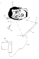
ここで図面を参照すると、カメラで補助されるナビゲーションシステムのコンピュータおよびディスプレイが、概略的に示されており、全体として参照番号9で示される。このコンピュータは、ケーブル接続8によって、カメラ架台4に接続され、標的領域をモニタするための2つの赤外線カメラ5および6が、互いに間隔をあけてこのカメラ架台に取り付けられている。
【0046】
この場合には、図示されたヒトの頭部の位置が、参照または記録されるべきものである。この目的で、光ビーム放出器1が使用され、これは、赤外レーザ光ビーム2を患者の顔面に投射する。光ビーム放出器1は、第二位置で破線で示され、参照の間の一定の揺動を示す。
【0047】
次いで、顔面が参照用光ビーム2によって走査され、結果として光反射または光スポット3が、その表面に連続的に発生する。図面においては、このような光マークのいくつかのみを、例として(すなわち、このような光スポットのラインによって)示す。しかし、これらのスポットまたは反射はまた、ビーム放出によって、適切な位置に個別に発生し得る。
【0048】
実際の処置の前に、処置を実施する人物は、単に、光ビーム放出器1を持ち、そして顔面を光ビーム2を用いて時々走査するのみである。単一の画像の連続における迅速な記録のため、カメラシステムは、各々が順に並んだそれぞれの光反射3を発生させ、単一の光スポットについてのその光路は、図面において一点鎖線7により示される。2つのカメラは、光反射の空間的位置を三次元的にマッピングし得、そしてコンピュータシステム9は、検出された光マークのデータから、顔面に帰属された光スポットの位置を決定し得る。
【0049】
患者の頭部の走査から得られるデータ、および従ってその顔面についてのデータは、コンピュータに格納される。次いで、このコンピュータは、マッチングルーチンの補助により、光ビームによる参照から得られた画像化スポットの数が、その表面の検出された表面ポイント(走査データセットによりコンピュータが知る)を帰属するか、またはそれを調和させるために十分であるか否かを、連続的に決定する。一旦、十分な一致が存在すれば、聴覚的および/または視覚的なシグナルが出力されて、処置を実施する人物に、参照が首尾よく完結したことを示す。
【0050】
このように発生した画像化スポット3は、従来別個に使用されたような、取り付けられるマークまたは他の様式で適用されるマークの必要性を排除する。得られる複数の光スポット3は、高度に正確な参照の実施を可能とする。
【0051】
参照アダプタ10が患者の頭部に固定的に配置されることもまた、この図面に概略的に示される。このアダプタは3つの反射体を備え、これらの反射体の位置は、カメラ5、6により同様に追跡され得る。参照の間に患者の頭部を回転させること、またはカメラ5、6を移動させることが、カメラシェード(例えば、外鼻孔による)を排除するためには必要となり、この相対的な動きはアダプタ10の補助により追跡され、そして参照において考慮されて、検出誤差が回避される。
【0052】
すでに記載したように、光ビーム放出器1は、不可視光ビーム2に加えて、可視光ビームをも投射し得る。この可視光ビームは、同じ方向および同じ焦点を有し、処置を実施する人物が発生する光スポットの視覚的追跡を維持することを可能にし、そして目にビーム放出することを防止し得る。
【0053】
本発明による参照システムは、画像により補助される手術を含む、すべての処置方法と共に利用され得る。このシステムは、外科手術および放射線処置の両方に適用される。参照はまた、受動的マークアレイを有する追跡システムならびに能動的発光マークを有する追跡システム(例えば、追跡用医療機器において使用されるもの)のために、利用され得る。これまでは主として、光マークは患者の皮膚の表面の光ビームによって発生することが示されたが、処置のためにこの様式ですでに暴露された骨構造(例えば、暴露された頭蓋骨または脊椎の骨部分)を参照することもまた、本発明の範囲内であると想定される。
【0054】
本発明は、患者または患者の身体部分を、カメラに補助された医療用ナビゲーションシステムにおいて参照するための方法に関し、この方法は、以下の工程:
・参照されるべき患者の身体部分を、少なくとも2つのカメラ(5、6)によって補助されるナビゲーションシステムの検出範囲内にする工程であって、このナビゲーションシステムは、コンピュータの支持によって、光マーク(3)の三次元の空間的位置を検出する、工程、
・光マーク(3)が光ビーム(2)によって、参照されるべき身体部分の表面に発生される工程であって、光マーク(3)の三次元的位置が、カメラで補助されるナビゲーションシステムによって決定される、工程、
・参照されるべき身体部分の表面の三次元的位置が、光マーク(3)についての位置データによって決定される工程、
を包含する。
【0055】
本発明は、さらに、この方法を実施するための装置に関する。
【0056】
【発明の効果】
本発明により、患者または患者の身体部分を、カメラで補助される医療用ナビゲーションシステムにおいて参照するための、方法および装置が提供され、このことにより、先行技術に関する上に例示した欠点が克服された。特に、本発明は、参照の正確な手段を可能とし、これは、失敗が起こりにくく、そして簡単に実行され得る。
【図面の簡単な説明】
【図1】図1は、本発明による参照用装置の使用の概略図である。
【符号の説明】
2 光ビーム
3 光マーク
5、6 カメラ
10 マークアレイ[0001]
BACKGROUND OF THE INVENTION
The present invention relates to a method and apparatus for referencing or recording a patient or patient body part in a camera-assisted medical navigation system.
[0002]
[Prior art]
Surgery or radiation therapy is now increasingly performed with the aid of so-called navigation or tracking systems. In this context, patient data is determined by imaging techniques (eg, computer linked tomography or magnetic nuclear resonance tomography), which is based on the display output and temporarily presents the treatment instrument of the treating physician. It is used to show the doctor where to go. One application consists, for example, of displaying the position of the tip of the instrument inside the body part to be treated so that it is possible to operate accurately at the position to be treated. .
[0003]
In order for such a navigation system to work, it is necessary that the temporary position of the patient or patient body part to be treated is known in situ during the procedure. This updated position data can then be attributed to data received from the imaging process (eg, data from computer-aided tomography generated some time before the procedure). After this assignment, a computer assisted procedure can be initiated.
[0004]
According to the prior art, the above-mentioned attribution is achieved with the aid of a mark (i.e. with the aid of a patient's artificial or natural landmark). Thus, German Patent No. 196 39 615 suggests attaching an artificial mark to the patient's skin prior to tomographic scanning, and uses what is made from visible marks in tomographic images. . After tomography, the patient is taken to the operating room. As soon as the procedure starts, the patient or the patient's body part is referenced, where the mark applied to the patient is located by the pointer tool and the computer is assisted in the temporary position of the mark Can be tracked in the navigation system. Once the position of the mark is known, the positions of all other points from the tomographic data set can be detected at the updated position of the patient and a navigation assisted procedure can be initiated.
[0005]
However, the use of marks applied externally to the skin surface in this way has several drawbacks. For one, the surface of the skin can move easily and such movement results in inaccuracies between references. In particular, when targeting a mark using a pointer tool, the skin may be displaced slightly.
[0006]
However, too many artificial marks cannot be used to compensate for such inaccuracies. This is because references are unnecessarily delayed. For example, an invasive solution that marks the bone substance under the skin is uncomfortable for the patient, while a natural mark (eg, nasal root) is referred to so accurately. Often not.
[0007]
Another drawback of the method illustrated above is particularly evident when the procedure is not performed immediately after tomography. Thus, for example, some of the marks can be removed overnight, which can cause significant difficulties during reference. One particularly disadvantageous case is embodied when the removed mark is replaced somewhere else by the patient himself, which can even lead to erroneous treatment.
[0008]
A further navigation system based on providing reference marks is known from US Pat. No. 5,383,454, which utilizes actively emitting marks, which are provided separately, And likewise brings about the above-mentioned drawbacks.
[0009]
[Problems to be solved by the invention]
It is an object of the present invention to provide a method and apparatus for referencing a patient or patient body part in a camera assisted medical navigation system, which is exemplified above with respect to the prior art. Disadvantages are overcome. In particular, the present invention allows for an accurate means of reference, which is less prone to failure and can be easily implemented.
[0010]
[Means for Solving the Problems]
The present invention is a method for referencing or recording a patient or a patient's body part in a camera-assisted medical navigation system comprising the following steps:
Bringing the body part of the patient to be referred to within the detection range of a navigation system assisted by at least two cameras (5, 6), the navigation system being supported by a computer with a light mark (3) Detecting a three-dimensional spatial position of
A navigation system in which a light mark (3) is generated on the surface of a body part to be referenced by a light beam (2), the three-dimensional position of the light mark (3) being assisted by a camera Determined by the process, and
The three-dimensional position of the surface of the body part to be referenced is determined by the position data for the light mark (3),
A method comprising: This achieves the above object.
[0011]
In a preferred embodiment, the spatial location of the surface is attributed to the image data of a data set for updating and referencing a set of image data previously generated by an imaging technique with respect to the body part. And a method is provided in which the data set is in particular a CT, MRI (Magnetic Nuclear Resonance Tomography), PET, SPECT, X-ray or ultrasound scanning data set.
[0012]
In a preferred embodiment, a method is provided wherein the light beam is a beam of invisible light, in particular infrared light, and the camera (5, 6) is configured to detect light reflections. The
[0013]
In a preferred embodiment, a method is provided wherein the light beam is a laser light beam.
[0014]
In a preferred embodiment, a visible light reflection is generated on the surface by a second visible light beam directed to a target area substantially identical to the target area of the invisible reference light beam (2). A method is provided.
[0015]
In a preferred embodiment, a method is provided wherein the second light beam is a visible laser beam.
[0016]
In a preferred embodiment, a method is provided in which the two light beams are generated by two light sources arranged side by side or nested.
[0017]
In a preferred embodiment, a plurality of light marks are continuously generated on the surface by the reference light beam (2), while the generated light marks (3) are always, ie in particular, the above-mentioned A method is provided that is detected until a sufficient number of position data has been acquired to determine the spatial position.
[0018]
In a preferred embodiment, either the camera arrangement or the body part to be referenced is moved during the reference, so that the camera shade is eliminated and the relative motion of the body part is determined by the navigation system. A method is provided which is tracked by a mark array (10) arranged fixedly relative to a body part.
[0019]
The invention also provides a device for reference or recording of a patient or patient body part, a medical navigation system assisted by at least two cameras (5, 6), and the surface of the body part to be referred to Means for generating a light mark (3), the system detects, by computer support, the three-dimensional spatial position of the light mark (3) in the detection region, and the three-dimensional light mark (3) The spatial position of the is determined by a camera-assisted navigation system, where the device is a light beam emitter (1) for generating the light mark (3), with the light as a light mark on the surface An apparatus is provided that is characterized by reflection.
[0020]
In a preferred embodiment, the light beam emitter (1) is a beam emitter of invisible light, in particular infrared light, and the camera (5, 6) is set to capture light reflections. An apparatus is provided.
[0021]
In a preferred embodiment, there is provided an apparatus characterized in that the light beam emitter (1) is a laser light beam emitter.
[0022]
In a preferred embodiment, the light beam emitter (1) emits a second visible light beam directed to a target area substantially identical to the target area of the invisible reference light beam; An apparatus is provided wherein visible light reflection further occurs on the surface.
[0023]
In a preferred embodiment, there is provided an apparatus characterized in that the second light beam emitter is a visible laser beam emitter.
[0024]
In a preferred embodiment, an apparatus is provided in which the light source of the beam is integrated as a single light source or is two juxtaposed light sources or two nested light sources.
[0025]
In a preferred embodiment, the device comprises a mark array (10) fixedly arranged with respect to the body part, by means of the mark array relative to the body part to be referenced and the camera arrangement. An apparatus is provided that features tracking movement to eliminate camera shade between references.
[0026]
This object is achieved according to the present invention by a method for referencing or recording a patient or patient body part in a camera-assisted medical navigation system. This method includes the following steps:
Bringing the body part of the patient to be referred to within the detection range of a navigation system assisted by at least two cameras, the navigation system being supported by a computer with a three-dimensional spatial Detecting the position, process,
A light mark is generated on the surface of the body part to be referenced by a light beam, the three-dimensional position of the light mark being determined by a camera assisted navigation system; and
A step in which the three-dimensional position of the surface of the body part to be referenced is determined by the position data about the light mark.
[0027]
In other words, the present invention is a departure from applying separate marks on the surface of the patient's body part, and the present invention instead uses these marks to simply illuminate the surface (skin, bone). The beam is emitted to generate a spot of light on its surface, which spot is visible to the camera as a reflection of the mark. Then, when this surface is scanned by a light beam, a plurality of light marks are actually generated, and the structure of these light marks (each known as a three-dimensional light spot in space) causes the body part to be treated This produces a crowd or cloud of spots that are attributed to the surface. Theoretically, it is sufficient to detect only three spots, but the method becomes more stable as more spots are generated. A sufficient number of spots provides sufficient information and allows for highly accurate three-dimensional attribution of the surface. Tests have shown that a small number (about 20) of light spots already generated in this manner are sufficient to allow detection of the spatial location of body parts with high accuracy.
[0028]
In general, the area of the patient scanned by the light beam continues to be an area that facilitates reconfirmation in this form in the patient's corresponding data set, and therefore, what the patient does during the reference or recording. Reference or recording is possible even without being scanned, and then scanned by imaging techniques in the presence of such appendages (eg, tubes in the mouth or nose) already present.
[0029]
An advantage of the present invention is that, in addition to being able to achieve a high accuracy, in particular, it eliminates all problems that arise from using separately applied marks. Here, the reference is no longer bothered by marks that are likely to be displaced, moved or disengaged. References according to the present invention do not specifically include unpleasant side effects on the patient (eg, the pain of marks that are stuck in place or invasively fixed). Isolated false light marks or reflections, such as “runaways” (eg, beams reflected on surfaces other than desired) can be easily corrected by calculation.
[0030]
Another major advantage of the present invention is that the surgical procedure can be separated in time from the tomographic scan to a greater extent since no separate marks need to be attached. Since there is no substantial change in the patient's skin over a long period of time, a fairly accurate reference of the patient is possible after a few days of the tomographic scan, during which the patient holds the mark on the skin surface There is no need.
[0031]
Furthermore, the present invention is already advantageous when scanning a patient. In the past, special scans (navigation scans), ie scans that included marks visible by CT or MR, were performed. The present invention allows the scans to be performed without marks, in part allowing the scans to be temporally separated from the surgery, and further utilizing multiple scans for navigation purposes. Therefore, if the physician should establish that additional CT scans made a few weeks ago before the surgery would be useful during navigation, he would also be able to utilize this scan during navigation. It raises no problem. This is because the mark need not be imaged in such a scan.
[0032]
Furthermore, it is particularly advantageous that existing camera systems can be used with the technology according to the invention, i.e. no further devices, for example laser scanners, are required. Conventional methods where points are detected or recorded using a navigation pointer (ie, the surface of the bone is scanned using a pointer chip, the 3D coordinates of each of these points are stored, and then the clouds of these points are stored. Is mathematically matched to the surface obtained from CT scan data), the method according to the invention allows increased accuracy and faster detection.
[0033]
The reference according to the invention can be utilized for any surgery requiring a temporary three-dimensional position of the patient's body part to be determined. However, the present invention provides a set of image data (especially CT, MRI (magnetic nuclear resonance tomography), PET, SPECT, X It is particularly suitable for the method of updating and referring to the image data of this data set attributed to a line or ultrasound scan data set).
[0034]
In order for the method according to the invention to work properly, it is essentially advantageous if a clearly identifiable light spot is generated as a light mark on the surface of the patient's body part. Therefore, the beam should be directed to its collision position as much as possible. In this aspect, it is particularly advantageous to use a beam of invisible light. This is because the light spots produced thereby can be clearly distinguished from light reflections caused by room light or other light that illuminates the patient's body part. In this aspect, it is advantageous to use an infrared beam, in which case the camera is set to detect this light reflection. Very well defined and oriented light marks are obtained by using laser light.
[0035]
As suggested above, in the case of generating an optical mark using invisible light, it is difficult in principle to establish a position where a light beam is emitted at an arbitrary time. In order to solve this problem, the method according to the invention is advantageously implemented so that a visible light reflection is directed to a target area substantially identical to the invisible reference light beam. Generated on the surface by a beam of light. With the assistance of this second light beam, it is possible to clearly know where the invisible reference light beam occurs. This second light beam may also be a laser light beam. This embodiment illustrated here is also advantageous in avoiding danger. As already mentioned above, it is advantageous to use an invisible laser light beam as a reference light beam by being able to generate a well-defined light mark. This light beam is invisible to the human eye, and even if the beam is accidentally emitted to an open eye, it does not cause blinking of the eyelids, so there is a risk of injury (eg, retinal burns). However, as suggested in accordance with the preferred embodiment, when a second beam of visible light is used, on the one hand it acts as a targeting aid to exclude sensitive areas (eg eyes) from irradiation. On the other hand, when this visible light enters the eye, it promotes blinking of the eyelids, thus preventing corneal burns.
[0036]
In principle, there are several possibilities for generating two light beams. Thus, for example, two light sources arranged side by side or nested can be used. Of course, there is also the possibility of utilizing a single light source that emits both visible and invisible light beams.
[0037]
In another preferred embodiment of the method, several light marks (spots) are generated continuously on the surface by a reference light beam, while the position of the generated light marks is always (ie In particular, until a sufficient number of position data is obtained to determine its spatial position). In this connection, whether or not the computer already has enough light marks for the attribution of the referenced amount of spots from the image data set (e.g. tomography) to the surface by means of a matching method. It is also possible to have a continuous inspection during the reference. At some point, if sufficient data is available, a visual or audible signal may be output to indicate a successful reference.
[0038]
In another advantageous embodiment of the method according to the invention, the body part to be referenced is moved during the reference so that the camera shade is eliminated and the movement of the body part is It is tracked in the navigation system by means of a mark array fixedly arranged with respect to the part. Since these cameras are usually fixedly installed, a spot is embodied at a specific position located on the camera shade (particularly behind the nostril when referring to the face). Thus, it is advantageous to move the patient if it is desired to emit a beam to these points with optical marks and to map these marks. In order to avoid this motion from misdetecting, this motion must be tracked in the navigation system, and this tracking is performed using the illustrated mark array (ie, for example, 3 with a known mark array). (Via arm-based Mayfield reference adapter).
[0039]
In accordance with the present invention, there is further provided an apparatus for referencing or recording a patient or a patient's body part, the apparatus being a medical navigation system assisted by at least two cameras, and a surface of the body part to be referenced. Means for generating a light mark, the navigation system detects, by computer support, the three-dimensional spatial position of the light mark in the area being detected, and the three-dimensional spatial position of the light mark is The means for generating a light mark, detected by a camera assisted navigation system, is a light beam emitter, which generates a reflection of light as a light mark on its surface. The light beam emitter can be a beam emitter of invisible light, in particular infrared light, and the camera is set to detect the reflection of this light. Further, the light beam emitter can be a laser light beam emitter.
[0040]
Preferably, the light beam emitter is capable of projecting a second visible light beam directed to a target area substantially the same as the target area of the invisible reference light beam, the reflection of visible light being reflected on the surface Further occurs. This second light beam emitter may also emit visible laser light. In this arrangement, the light source for the light beam emitter can be integrated into a single light source or can be two juxtaposed or nested light sources.
[0041]
Preferably, the device includes a mark array, the mark array being fixedly arranged with respect to the body part, whereby the body part to be referenced is tracked during the movement during the reference, Eliminate camera shades.
[0042]
Of course, conversely, camera movement can also be tracked. In most cases, it is advantageous if the body part of the patient to be treated remains stationary during the procedure and during reference or recording. In this case, the camera shade can be avoided by changing the position of the camera itself. Since the mark array provides images from different camera angles, again the relative movement between the camera and the body part can be tracked and considered during the reference.
[0043]
The advantages achieved with the device according to the invention have already been described with respect to the method according to the invention.
[0044]
DETAILED DESCRIPTION OF THE INVENTION
The invention will be described in detail by way of example with reference to a single diagram that schematically illustrates the use of a reference device according to the invention. Thereby, the patient or the patient's body part is referenced or recorded.
[0045]
Referring now to the drawings, a computer-assisted navigation system computer and display are schematically shown and generally designated by the reference numeral 9. This computer is connected to the camera mount 4 by a
[0046]
In this case, the position of the illustrated human head is to be referenced or recorded. For this purpose, a
[0047]
The face is then scanned with the reference light beam 2, resulting in a continuous light reflection or
[0048]
Prior to the actual treatment, the person performing the treatment simply has the
[0049]
Data obtained from a scan of the patient's head, and thus data about the face, is stored in a computer. The computer can then, with the aid of the matching routine, assign the number of imaging spots obtained from the reference by the light beam to the detected surface point of that surface (known by the computer from the scanning data set), or It is continuously determined whether it is sufficient to harmonize it. Once there is sufficient agreement, an audio and / or visual signal is output to indicate to the person performing the procedure that the reference has been successfully completed.
[0050]
The
[0051]
It is also schematically shown in this figure that the reference adapter 10 is fixedly placed on the patient's head. This adapter comprises three reflectors, and the position of these reflectors can be tracked by the
[0052]
As already described, the
[0053]
The reference system according to the present invention can be utilized with all treatment methods, including image assisted surgery. This system applies to both surgical and radiological procedures. Reference can also be utilized for tracking systems having passive mark arrays as well as tracking systems having active light emitting marks (eg, those used in tracking medical devices). Until now, light marks have mainly been shown to be generated by a light beam on the surface of a patient's skin, but bone structures that have already been exposed in this manner for treatment (e.g., exposed skulls or vertebrae). Reference to (bone part) is also considered to be within the scope of the present invention.
[0054]
The present invention relates to a method for referencing a patient or patient body part in a medical navigation system assisted by a camera, which method comprises the following steps:
Bringing the patient's body part to be referred to within the detection range of a navigation system assisted by at least two cameras (5, 6), which is supported by a computer with a light mark ( 3) detecting a three-dimensional spatial position,
A navigation system in which the light mark (3) is generated on the surface of the body part to be referenced by the light beam (2), the three-dimensional position of the light mark (3) being assisted by the camera Determined by the process,
The three-dimensional position of the surface of the body part to be referenced is determined by position data about the light mark (3),
Is included.
[0055]
The invention further relates to an apparatus for carrying out this method.
[0056]
【Effect of the invention】
The present invention provides a method and apparatus for referencing a patient or patient body part in a camera-assisted medical navigation system, which overcomes the above-illustrated shortcomings of the prior art. . In particular, the present invention allows for an accurate means of reference, which is less prone to failure and can be easily implemented.
[Brief description of the drawings]
FIG. 1 is a schematic diagram of the use of a reference device according to the present invention.
[Explanation of symbols]
2 Light beam
3 Light mark
5, 6 camera
10 Mark array
Claims (8)
Applications Claiming Priority (2)
| Application Number | Priority Date | Filing Date | Title |
|---|---|---|---|
| EP00107088.7 | 2000-04-05 | ||
| EP00107088A EP1142536B1 (en) | 2000-04-05 | 2000-04-05 | Patient referencing in a medical navigation system using projected light points |
Publications (2)
| Publication Number | Publication Date |
|---|---|
| JP2002035007A JP2002035007A (en) | 2002-02-05 |
| JP4938933B2 true JP4938933B2 (en) | 2012-05-23 |
Family
ID=8168347
Family Applications (1)
| Application Number | Title | Priority Date | Filing Date |
|---|---|---|---|
| JP2001106535A Expired - Lifetime JP4938933B2 (en) | 2000-04-05 | 2001-04-04 | Reference or record of a patient or patient body part in a medical navigation system by illuminating a light point |
Country Status (6)
| Country | Link |
|---|---|
| US (2) | US6873867B2 (en) |
| EP (1) | EP1142536B1 (en) |
| JP (1) | JP4938933B2 (en) |
| AT (1) | ATE221344T1 (en) |
| DE (1) | DE50000335D1 (en) |
| ES (1) | ES2180481T3 (en) |
Cited By (2)
| Publication number | Priority date | Publication date | Assignee | Title |
|---|---|---|---|---|
| KR20190096178A (en) | 2018-02-08 | 2019-08-19 | 성균관대학교산학협력단 | Method for surface registration of surgical navigation and surgical navigation apparatus |
| KR20190102429A (en) | 2018-02-26 | 2019-09-04 | 성균관대학교산학협력단 | Methods and apparatuses for surface registration of surgical navigation |
Families Citing this family (147)
| Publication number | Priority date | Publication date | Assignee | Title |
|---|---|---|---|---|
| US7547307B2 (en) * | 2001-02-27 | 2009-06-16 | Smith & Nephew, Inc. | Computer assisted knee arthroplasty instrumentation, systems, and processes |
| US20050113846A1 (en) * | 2001-02-27 | 2005-05-26 | Carson Christopher P. | Surgical navigation systems and processes for unicompartmental knee arthroplasty |
| ATE431111T1 (en) * | 2001-02-27 | 2009-05-15 | Smith & Nephew Inc | DEVICE FOR TOTAL KNEE CONSTRUCTION |
| WO2003034705A2 (en) * | 2001-10-19 | 2003-04-24 | University Of North Carolina At Chapel Hill | Methods and systems for dynamic virtual convergence and head mountable display |
| CA2475979A1 (en) * | 2002-02-11 | 2003-08-21 | Smith & Nephew, Inc. | Image-guided fracture reduction |
| ES2225668T3 (en) * | 2002-03-01 | 2005-03-16 | Brainlab Ag | LAMP FOR OPERATION ROOM, INCLUDING A CAMERA SYSTEM FOR THREE-DIMENSIONAL REFERENCE. |
| US7998062B2 (en) | 2004-03-29 | 2011-08-16 | Superdimension, Ltd. | Endoscope structures and techniques for navigating to a target in branched structure |
| AU2003237922A1 (en) * | 2002-06-13 | 2003-12-31 | Moller-Wedel Gmbh | Method and instrument for surgical navigation |
| US20110015518A1 (en) | 2002-06-13 | 2011-01-20 | Martin Schmidt | Method and instrument for surgical navigation |
| EP2070487B1 (en) | 2002-08-13 | 2014-03-05 | NeuroArm Surgical, Ltd. | Microsurgical robot system |
| WO2004030556A2 (en) | 2002-10-04 | 2004-04-15 | Orthosoft Inc. | Computer-assisted hip replacement surgery |
| DE602004022432D1 (en) * | 2003-09-15 | 2009-09-17 | Super Dimension Ltd | SYSTEM FROM ACCESSORIES FOR USE WITH BRONCHOSCOPES |
| EP2316328B1 (en) | 2003-09-15 | 2012-05-09 | Super Dimension Ltd. | Wrap-around holding device for use with bronchoscopes |
| US7862570B2 (en) | 2003-10-03 | 2011-01-04 | Smith & Nephew, Inc. | Surgical positioners |
| WO2005032390A1 (en) | 2003-10-09 | 2005-04-14 | Ap Technologies Sa | Robot-assisted medical treatment device |
| US20050085822A1 (en) * | 2003-10-20 | 2005-04-21 | Thornberry Robert C. | Surgical navigation system component fault interfaces and related processes |
| US7764985B2 (en) * | 2003-10-20 | 2010-07-27 | Smith & Nephew, Inc. | Surgical navigation system component fault interfaces and related processes |
| ES2362491T3 (en) | 2003-11-14 | 2011-07-06 | SMITH & NEPHEW, INC. | ADJUSTABLE SURGICAL CUTTING SYSTEMS. |
| WO2005053559A1 (en) * | 2003-11-25 | 2005-06-16 | Smith & Nephew, Inc. | Methods and apparatuses for providing a navigational array |
| US20050113659A1 (en) * | 2003-11-26 | 2005-05-26 | Albert Pothier | Device for data input for surgical navigation system |
| US7376492B2 (en) * | 2003-12-04 | 2008-05-20 | Matrix Electronic Measuring, L.P. | System for measuring points on a vehicle during damage repair |
| US7120524B2 (en) * | 2003-12-04 | 2006-10-10 | Matrix Electronic Measuring, L.P. | System for measuring points on a vehicle during damage repair |
| US20050234332A1 (en) * | 2004-01-16 | 2005-10-20 | Murphy Stephen B | Method of computer-assisted ligament balancing and component placement in total knee arthroplasty |
| US20050159759A1 (en) * | 2004-01-20 | 2005-07-21 | Mark Harbaugh | Systems and methods for performing minimally invasive incisions |
| CA2553842A1 (en) * | 2004-01-22 | 2005-08-04 | Smith & Nephew, Inc. | Methods, systems, and apparatuses for providing patient-mounted surgical navigational sensors |
| US8764725B2 (en) | 2004-02-09 | 2014-07-01 | Covidien Lp | Directional anchoring mechanism, method and applications thereof |
| ATE503419T1 (en) | 2004-02-20 | 2011-04-15 | Univ Florida | SYSTEM FOR ADMINISTERING CONFORMAL RADIATION THERAPY WHILE IMAGING SOFT TISSUE |
| US20050234465A1 (en) * | 2004-03-31 | 2005-10-20 | Mccombs Daniel L | Guided saw with pins |
| US20050234466A1 (en) * | 2004-03-31 | 2005-10-20 | Jody Stallings | TLS adjustable block |
| US20050228404A1 (en) * | 2004-04-12 | 2005-10-13 | Dirk Vandevelde | Surgical navigation system component automated imaging navigation and related processes |
| US20070287910A1 (en) * | 2004-04-15 | 2007-12-13 | Jody Stallings | Quick Disconnect and Repositionable Reference Frame for Computer Assisted Surgery |
| EP1737375B1 (en) * | 2004-04-21 | 2021-08-11 | Smith & Nephew, Inc | Computer-aided navigation systems for shoulder arthroplasty |
| US20050279368A1 (en) * | 2004-06-16 | 2005-12-22 | Mccombs Daniel L | Computer assisted surgery input/output systems and processes |
| US7749223B2 (en) * | 2004-08-09 | 2010-07-06 | Howmedica Osteonics Corp. | Navigated femoral axis finder |
| US20060200025A1 (en) * | 2004-12-02 | 2006-09-07 | Scott Elliott | Systems, methods, and apparatus for automatic software flow using instrument detection during computer-aided surgery |
| WO2006060632A1 (en) * | 2004-12-02 | 2006-06-08 | Smith & Nephew, Inc. | Systems for providing a reference plane for mounting an acetabular cup |
| EP1681028B1 (en) * | 2005-01-12 | 2014-03-26 | Brainlab AG | Video tracking and registration |
| US7760909B2 (en) * | 2005-01-12 | 2010-07-20 | Brainlab Ag | Video tracking and registering |
| US9492241B2 (en) | 2005-01-13 | 2016-11-15 | Mazor Robotics Ltd. | Image guided robotic system for keyhole neurosurgery |
| US20060161051A1 (en) * | 2005-01-18 | 2006-07-20 | Lauralan Terrill-Grisoni | Method of computer-assisted ligament balancing and component placement in total knee arthroplasty |
| WO2006091704A1 (en) | 2005-02-22 | 2006-08-31 | Smith & Nephew, Inc. | In-line milling system |
| WO2007010330A1 (en) | 2005-07-15 | 2007-01-25 | Gulhivair Holding Sa | Device and method for a computer-assisted internal bone digitising for orthopaedic surgery and traumatology |
| US20070078678A1 (en) * | 2005-09-30 | 2007-04-05 | Disilvestro Mark R | System and method for performing a computer assisted orthopaedic surgical procedure |
| US20070118055A1 (en) * | 2005-11-04 | 2007-05-24 | Smith & Nephew, Inc. | Systems and methods for facilitating surgical procedures involving custom medical implants |
| JP4836122B2 (en) * | 2006-02-09 | 2011-12-14 | 国立大学法人浜松医科大学 | Surgery support apparatus, method and program |
| US7406860B2 (en) * | 2006-04-28 | 2008-08-05 | Seagate Technology Llc | Atomic force microscopy scanning and image processing |
| EP1857070A1 (en) * | 2006-05-18 | 2007-11-21 | BrainLAB AG | Contactless medical registration with distance measurement |
| US8635082B2 (en) | 2006-05-25 | 2014-01-21 | DePuy Synthes Products, LLC | Method and system for managing inventories of orthopaedic implants |
| US20070299334A1 (en) * | 2006-06-16 | 2007-12-27 | Stefan Vilsmeier | Medical instrument with a touch-sensitive tip and light emission source |
| JP4738270B2 (en) * | 2006-07-14 | 2011-08-03 | 株式会社日立メディコ | Surgery support device |
| US20110057930A1 (en) * | 2006-07-26 | 2011-03-10 | Inneroptic Technology Inc. | System and method of using high-speed, high-resolution depth extraction to provide three-dimensional imagery for endoscopy |
| WO2008017051A2 (en) * | 2006-08-02 | 2008-02-07 | Inneroptic Technology Inc. | System and method of providing real-time dynamic imagery of a medical procedure site using multiple modalities |
| US8939920B2 (en) * | 2007-07-13 | 2015-01-27 | C-Rad Positioning Ab | Patient monitoring at radiation machines |
| US8905920B2 (en) | 2007-09-27 | 2014-12-09 | Covidien Lp | Bronchoscope adapter and method |
| US8265949B2 (en) | 2007-09-27 | 2012-09-11 | Depuy Products, Inc. | Customized patient surgical plan |
| US20090088763A1 (en) * | 2007-09-30 | 2009-04-02 | Aram Luke J | Customized Patient-Specific Bone Cutting Block with External Reference |
| WO2009094646A2 (en) | 2008-01-24 | 2009-07-30 | The University Of North Carolina At Chapel Hill | Methods, systems, and computer readable media for image guided ablation |
| US8340379B2 (en) | 2008-03-07 | 2012-12-25 | Inneroptic Technology, Inc. | Systems and methods for displaying guidance data based on updated deformable imaging data |
| WO2009122273A2 (en) | 2008-04-03 | 2009-10-08 | Superdimension, Ltd. | Magnetic interference detection system and method |
| EP2241253B1 (en) | 2009-04-15 | 2011-06-15 | BrainLAB AG | Method for completing a medicinal image database |
| US9449378B2 (en) | 2008-05-22 | 2016-09-20 | Matrix Electronic Measuring Properties, Llc | System and method for processing stereoscopic vehicle information |
| US8345953B2 (en) | 2008-05-22 | 2013-01-01 | Matrix Electronic Measuring Properties, Llc | Stereoscopic measurement system and method |
| US8326022B2 (en) | 2008-05-22 | 2012-12-04 | Matrix Electronic Measuring Properties, Llc | Stereoscopic measurement system and method |
| US8249332B2 (en) | 2008-05-22 | 2012-08-21 | Matrix Electronic Measuring Properties Llc | Stereoscopic measurement system and method |
| US8473032B2 (en) | 2008-06-03 | 2013-06-25 | Superdimension, Ltd. | Feature-based registration method |
| US8218847B2 (en) | 2008-06-06 | 2012-07-10 | Superdimension, Ltd. | Hybrid registration method |
| US8932207B2 (en) | 2008-07-10 | 2015-01-13 | Covidien Lp | Integrated multi-functional endoscopic tool |
| JP5011238B2 (en) * | 2008-09-03 | 2012-08-29 | 株式会社日立製作所 | Radiation imaging device |
| DE102008052976B4 (en) * | 2008-10-23 | 2018-06-21 | Advanced Realtime Tracking Gmbh | tracking system |
| US8554307B2 (en) | 2010-04-12 | 2013-10-08 | Inneroptic Technology, Inc. | Image annotation in image-guided medical procedures |
| US8641621B2 (en) * | 2009-02-17 | 2014-02-04 | Inneroptic Technology, Inc. | Systems, methods, apparatuses, and computer-readable media for image management in image-guided medical procedures |
| US8690776B2 (en) | 2009-02-17 | 2014-04-08 | Inneroptic Technology, Inc. | Systems, methods, apparatuses, and computer-readable media for image guided surgery |
| US11464578B2 (en) | 2009-02-17 | 2022-10-11 | Inneroptic Technology, Inc. | Systems, methods, apparatuses, and computer-readable media for image management in image-guided medical procedures |
| EP2226003B1 (en) | 2009-03-05 | 2015-05-06 | Brainlab AG | Medical image registration by means of optical coherence tomography |
| US8296860B2 (en) * | 2009-03-16 | 2012-10-23 | Seagate Technology Llc | Atomic force microscopy true shape measurement method |
| US8611984B2 (en) | 2009-04-08 | 2013-12-17 | Covidien Lp | Locatable catheter |
| US9668820B2 (en) | 2009-08-20 | 2017-06-06 | Brainlab Ag | Integrated surgical device combining instrument, tracking system and navigation system |
| EP2470102B1 (en) | 2009-08-27 | 2016-07-20 | Brainlab AG | Disposable and radiolucent reference array for optical tracking |
| US20110082351A1 (en) * | 2009-10-07 | 2011-04-07 | Inneroptic Technology, Inc. | Representing measurement information during a medical procedure |
| US9282947B2 (en) | 2009-12-01 | 2016-03-15 | Inneroptic Technology, Inc. | Imager focusing based on intraoperative data |
| US8235530B2 (en) * | 2009-12-07 | 2012-08-07 | C-Rad Positioning Ab | Object positioning with visual feedback |
| US8518094B2 (en) * | 2010-03-02 | 2013-08-27 | Bwt Property, Inc. | Precisely guided phototherapy apparatus |
| US8781186B2 (en) * | 2010-05-04 | 2014-07-15 | Pathfinder Therapeutics, Inc. | System and method for abdominal surface matching using pseudo-features |
| US10582834B2 (en) | 2010-06-15 | 2020-03-10 | Covidien Lp | Locatable expandable working channel and method |
| FR2963693B1 (en) | 2010-08-04 | 2013-05-03 | Medtech | PROCESS FOR AUTOMATED ACQUISITION AND ASSISTED ANATOMICAL SURFACES |
| DE102010042278A1 (en) * | 2010-10-11 | 2012-04-12 | Siemens Aktiengesellschaft | Operation navigation system with structured light |
| DE102010064320B4 (en) * | 2010-12-29 | 2019-05-23 | Siemens Healthcare Gmbh | Optical pointer for a surgical assistance system |
| US9586817B2 (en) | 2011-07-28 | 2017-03-07 | Seagate Technology Llc | Semi-auto scanning probe microscopy scanning |
| FR2983059B1 (en) | 2011-11-30 | 2014-11-28 | Medtech | ROBOTIC-ASSISTED METHOD OF POSITIONING A SURGICAL INSTRUMENT IN RELATION TO THE BODY OF A PATIENT AND DEVICE FOR CARRYING OUT SAID METHOD |
| US8668345B2 (en) | 2011-11-30 | 2014-03-11 | Izi Medical Products | Retro-reflective marker with snap on threaded post |
| US8670816B2 (en) | 2012-01-30 | 2014-03-11 | Inneroptic Technology, Inc. | Multiple medical device guidance |
| US8661573B2 (en) | 2012-02-29 | 2014-03-04 | Izi Medical Products | Protective cover for medical device having adhesive mechanism |
| WO2013152790A1 (en) | 2012-04-12 | 2013-10-17 | Brainlab Ag | Optical sampling of surface points for medical navigation |
| US10561861B2 (en) | 2012-05-02 | 2020-02-18 | Viewray Technologies, Inc. | Videographic display of real-time medical treatment |
| US9186053B2 (en) | 2012-05-03 | 2015-11-17 | Covidien Lp | Methods of using light to repair hernia defects |
| US9642606B2 (en) | 2012-06-27 | 2017-05-09 | Camplex, Inc. | Surgical visualization system |
| US9629523B2 (en) | 2012-06-27 | 2017-04-25 | Camplex, Inc. | Binocular viewing assembly for a surgical visualization system |
| JP6382208B2 (en) | 2012-10-26 | 2018-08-29 | ビューレイ・テクノロジーズ・インコーポレイテッドViewRay Technologies, Inc. | System and computer program product |
| US9782159B2 (en) | 2013-03-13 | 2017-10-10 | Camplex, Inc. | Surgical visualization systems |
| US10314559B2 (en) | 2013-03-14 | 2019-06-11 | Inneroptic Technology, Inc. | Medical device guidance |
| US9446263B2 (en) | 2013-03-15 | 2016-09-20 | Viewray Technologies, Inc. | Systems and methods for linear accelerator radiotherapy with magnetic resonance imaging |
| US10881286B2 (en) | 2013-09-20 | 2021-01-05 | Camplex, Inc. | Medical apparatus for use with a surgical tubular retractor |
| WO2015042460A1 (en) | 2013-09-20 | 2015-03-26 | Camplex, Inc. | Surgical visualization systems and displays |
| DE102014210051A1 (en) | 2014-05-27 | 2015-12-03 | Carl Zeiss Meditec Ag | Method and device for determining a surface topography of a body |
| US10952593B2 (en) | 2014-06-10 | 2021-03-23 | Covidien Lp | Bronchoscope adapter |
| US9901406B2 (en) | 2014-10-02 | 2018-02-27 | Inneroptic Technology, Inc. | Affected region display associated with a medical device |
| ES2649747T3 (en) * | 2014-11-26 | 2018-01-15 | Masmec S.P.A. | Computer-assisted system to guide a surgical / diagnostic instrument in a patient's body |
| WO2016090336A1 (en) | 2014-12-05 | 2016-06-09 | Camplex, Inc. | Surgical visualization systems and displays |
| US10188467B2 (en) | 2014-12-12 | 2019-01-29 | Inneroptic Technology, Inc. | Surgical guidance intersection display |
| EP3250104B1 (en) * | 2015-01-28 | 2019-03-06 | Brainlab AG | Light point identification method |
| CA2962652C (en) * | 2015-03-17 | 2019-12-03 | Synaptive Medical (Barbados) Inc. | Method and device for registering surgical images |
| WO2016154589A1 (en) | 2015-03-25 | 2016-09-29 | Camplex, Inc. | Surgical visualization systems and displays |
| US10426555B2 (en) | 2015-06-03 | 2019-10-01 | Covidien Lp | Medical instrument with sensor for use in a system and method for electromagnetic navigation |
| JP2018533775A (en) | 2015-07-17 | 2018-11-15 | コーニンクレッカ フィリップス エヌ ヴェKoninklijke Philips N.V. | Device and method for determining the position of a mobile device with respect to a subject |
| US9949700B2 (en) | 2015-07-22 | 2018-04-24 | Inneroptic Technology, Inc. | Medical device approaches |
| JP2018535022A (en) | 2015-11-24 | 2018-11-29 | ビューレイ・テクノロジーズ・インコーポレイテッドViewRay Technologies, Inc. | Radiation beam collimation system and method |
| WO2017091704A1 (en) | 2015-11-25 | 2017-06-01 | Camplex, Inc. | Surgical visualization systems and displays |
| US9675319B1 (en) | 2016-02-17 | 2017-06-13 | Inneroptic Technology, Inc. | Loupe display |
| CN109310879A (en) | 2016-03-02 | 2019-02-05 | 优瑞技术公司 | Utilize the Part Ther of magnetic resonance imaging |
| US10478254B2 (en) | 2016-05-16 | 2019-11-19 | Covidien Lp | System and method to access lung tissue |
| KR20190043129A (en) | 2016-06-22 | 2019-04-25 | 뷰레이 테크놀로지스 인크. | Magnetic Resonance Imaging at Weak Field Strength |
| CN106388947B (en) * | 2016-09-30 | 2019-04-12 | 江苏风和医疗器材股份有限公司 | A kind of stapler percussion force detection method |
| AU2017340607B2 (en) | 2016-10-05 | 2022-10-27 | Nuvasive, Inc. | Surgical navigation system and related methods |
| US10278778B2 (en) | 2016-10-27 | 2019-05-07 | Inneroptic Technology, Inc. | Medical device navigation using a virtual 3D space |
| US10722311B2 (en) | 2016-10-28 | 2020-07-28 | Covidien Lp | System and method for identifying a location and/or an orientation of an electromagnetic sensor based on a map |
| US10446931B2 (en) | 2016-10-28 | 2019-10-15 | Covidien Lp | Electromagnetic navigation antenna assembly and electromagnetic navigation system including the same |
| US10517505B2 (en) | 2016-10-28 | 2019-12-31 | Covidien Lp | Systems, methods, and computer-readable media for optimizing an electromagnetic navigation system |
| US10792106B2 (en) | 2016-10-28 | 2020-10-06 | Covidien Lp | System for calibrating an electromagnetic navigation system |
| US10418705B2 (en) | 2016-10-28 | 2019-09-17 | Covidien Lp | Electromagnetic navigation antenna assembly and electromagnetic navigation system including the same |
| US10751126B2 (en) | 2016-10-28 | 2020-08-25 | Covidien Lp | System and method for generating a map for electromagnetic navigation |
| US10615500B2 (en) | 2016-10-28 | 2020-04-07 | Covidien Lp | System and method for designing electromagnetic navigation antenna assemblies |
| US10638952B2 (en) | 2016-10-28 | 2020-05-05 | Covidien Lp | Methods, systems, and computer-readable media for calibrating an electromagnetic navigation system |
| EP3827883B1 (en) | 2016-12-13 | 2023-11-15 | ViewRay Technologies, Inc. | Radiation therapy systems |
| US10918455B2 (en) | 2017-05-08 | 2021-02-16 | Camplex, Inc. | Variable light source |
| US11259879B2 (en) | 2017-08-01 | 2022-03-01 | Inneroptic Technology, Inc. | Selective transparency to assist medical device navigation |
| US11219489B2 (en) | 2017-10-31 | 2022-01-11 | Covidien Lp | Devices and systems for providing sensors in parallel with medical tools |
| WO2019112880A1 (en) | 2017-12-06 | 2019-06-13 | Viewray Technologies, Inc. | Optimization of multimodal radiotherapy |
| US11484365B2 (en) | 2018-01-23 | 2022-11-01 | Inneroptic Technology, Inc. | Medical image guidance |
| US11209509B2 (en) | 2018-05-16 | 2021-12-28 | Viewray Technologies, Inc. | Resistive electromagnet systems and methods |
| US11051829B2 (en) | 2018-06-26 | 2021-07-06 | DePuy Synthes Products, Inc. | Customized patient-specific orthopaedic surgical instrument |
| EP3824621A4 (en) | 2018-07-19 | 2022-04-27 | Activ Surgical, Inc. | Systems and methods for multi-modal sensing of depth in vision systems for automated surgical robots |
| JP2022526626A (en) | 2019-04-08 | 2022-05-25 | アクティブ サージカル, インコーポレイテッド | Systems and methods for medical imaging |
| CN114599263A (en) | 2019-08-21 | 2022-06-07 | 艾科缇弗外科公司 | System and method for medical imaging |
| US11612440B2 (en) | 2019-09-05 | 2023-03-28 | Nuvasive, Inc. | Surgical instrument tracking devices and related methods |
| CN110547872B (en) * | 2019-09-23 | 2021-08-10 | 重庆博仕康科技有限公司 | Operation navigation registration system |
| CN113576663B (en) * | 2021-07-30 | 2023-06-27 | 武汉联影智融医疗科技有限公司 | Probe device for contact positioning and positioning system |
| DE102022202555A1 (en) | 2022-03-15 | 2023-09-21 | Carl Zeiss Meditec Ag | Method for determining the three-dimensional positions of points of a target region on a patient in a reference coordinate system of a surgical visualization system and surgical visualization system |
Family Cites Families (19)
| Publication number | Priority date | Publication date | Assignee | Title |
|---|---|---|---|---|
| US4597380A (en) * | 1982-09-30 | 1986-07-01 | Laser Industries Ltd. | Endoscopic attachment to a surgical laser |
| US5417212A (en) * | 1988-11-21 | 1995-05-23 | Szeles; Josef C. | Apparatus for determining the location of receptor regions |
| FR2652928B1 (en) * | 1989-10-05 | 1994-07-29 | Diadix Sa | INTERACTIVE LOCAL INTERVENTION SYSTEM WITHIN A AREA OF A NON-HOMOGENEOUS STRUCTURE. |
| US5198877A (en) * | 1990-10-15 | 1993-03-30 | Pixsys, Inc. | Method and apparatus for three-dimensional non-contact shape sensing |
| EP0931516B1 (en) * | 1990-10-19 | 2008-08-20 | St. Louis University | Surgical probe locating system for head use |
| US6006126A (en) * | 1991-01-28 | 1999-12-21 | Cosman; Eric R. | System and method for stereotactic registration of image scan data |
| US6143003A (en) * | 1995-01-31 | 2000-11-07 | Cosman; Eric R. | Repositioner for head, neck, and body |
| US5603318A (en) * | 1992-04-21 | 1997-02-18 | University Of Utah Research Foundation | Apparatus and method for photogrammetric surgical localization |
| JPH07129322A (en) * | 1993-09-07 | 1995-05-19 | Sony Corp | Computer display system |
| AU3621795A (en) | 1994-09-28 | 1996-04-19 | William Richard Fright | Arbitrary-geometry laser surface scanner |
| DE4442608C1 (en) * | 1994-11-30 | 1996-08-08 | Siemens Ag | Stereotactic additional device for carrying out biopsy guided by pattern |
| JP2611188B2 (en) * | 1994-11-30 | 1997-05-21 | 工業技術院長 | Biological measurement reference point setting method and apparatus |
| DE19639615C5 (en) * | 1996-09-26 | 2008-11-06 | Brainlab Ag | Reflector referencing system for surgical and medical instruments |
| AUPN929096A0 (en) * | 1996-04-17 | 1996-05-09 | Lions Eye Institute | A system for ocular ultramicrosurgery |
| US5891158A (en) * | 1997-10-23 | 1999-04-06 | Manwaring; Kim H. | Method and system for directing an instrument to a target |
| CA2318252A1 (en) * | 1998-01-28 | 1999-08-05 | Eric R. Cosman | Optical object tracking system |
| JPH11326057A (en) * | 1998-05-20 | 1999-11-26 | Kao Corp | Measuring method and device for three-dimensional object |
| JP2000039310A (en) * | 1998-07-22 | 2000-02-08 | Sanyo Electric Co Ltd | Method and device for measuring shape |
| DE19838590A1 (en) * | 1998-08-25 | 2000-03-09 | Siemens Ag | Magnetic resonance imaging for moving object |
-
2000
- 2000-04-05 ES ES00107088T patent/ES2180481T3/en not_active Expired - Lifetime
- 2000-04-05 AT AT00107088T patent/ATE221344T1/en not_active IP Right Cessation
- 2000-04-05 EP EP00107088A patent/EP1142536B1/en not_active Expired - Lifetime
- 2000-04-05 DE DE50000335T patent/DE50000335D1/en not_active Expired - Lifetime
-
2001
- 2001-04-04 JP JP2001106535A patent/JP4938933B2/en not_active Expired - Lifetime
- 2001-04-05 US US09/827,253 patent/US6873867B2/en not_active Expired - Lifetime
-
2005
- 2005-02-22 US US11/063,139 patent/US7577474B2/en not_active Expired - Lifetime
Cited By (2)
| Publication number | Priority date | Publication date | Assignee | Title |
|---|---|---|---|---|
| KR20190096178A (en) | 2018-02-08 | 2019-08-19 | 성균관대학교산학협력단 | Method for surface registration of surgical navigation and surgical navigation apparatus |
| KR20190102429A (en) | 2018-02-26 | 2019-09-04 | 성균관대학교산학협력단 | Methods and apparatuses for surface registration of surgical navigation |
Also Published As
| Publication number | Publication date |
|---|---|
| EP1142536B1 (en) | 2002-07-31 |
| US6873867B2 (en) | 2005-03-29 |
| US20020002330A1 (en) | 2002-01-03 |
| US20050143645A1 (en) | 2005-06-30 |
| US7577474B2 (en) | 2009-08-18 |
| ATE221344T1 (en) | 2002-08-15 |
| ES2180481T3 (en) | 2003-02-16 |
| EP1142536A1 (en) | 2001-10-10 |
| DE50000335D1 (en) | 2002-09-05 |
| JP2002035007A (en) | 2002-02-05 |
Similar Documents
| Publication | Publication Date | Title |
|---|---|---|
| JP4938933B2 (en) | Reference or record of a patient or patient body part in a medical navigation system by illuminating a light point | |
| US10716634B2 (en) | 3D system and method for guiding objects | |
| JP4836122B2 (en) | Surgery support apparatus, method and program | |
| US6533455B2 (en) | Method for determining a coordinate transformation for use in navigating an object | |
| US20070299334A1 (en) | Medical instrument with a touch-sensitive tip and light emission source | |
| US6317616B1 (en) | Method and system to facilitate image guided surgery | |
| CA2161430C (en) | System and method for indicating the position of a surgical probe | |
| US5447154A (en) | Method for determining the position of an organ | |
| US6724922B1 (en) | Verification of positions in camera images | |
| JP2732618B2 (en) | Anatomical imaging device | |
| JPH08509144A (en) | System to locate relative position of objects | |
| CN108290053B (en) | Image guided focused ultrasound therapy device and aiming device | |
| JP2004243140A (en) | Reference marker embedded in part of human body | |
| CN111936074A (en) | Monitoring moving objects in an operating room | |
| KR20220100613A (en) | Method and system for reproducing the insertion point of a medical device | |
| US20020172328A1 (en) | 3-D Navigation for X-ray imaging system | |
| JP2003522984A (en) | Laser pointer | |
| BR102022020744A2 (en) | ARRANGEMENT AND METHOD FOR RECORDING LIVE AND SCAN IMAGES | |
| Watson | Development of an interactive image-guided neurosurgical system |
Legal Events
| Date | Code | Title | Description |
|---|---|---|---|
| A621 | Written request for application examination |
Free format text: JAPANESE INTERMEDIATE CODE: A621 Effective date: 20080226 |
|
| A131 | Notification of reasons for refusal |
Free format text: JAPANESE INTERMEDIATE CODE: A131 Effective date: 20100831 |
|
| A521 | Request for written amendment filed |
Free format text: JAPANESE INTERMEDIATE CODE: A523 Effective date: 20101130 |
|
| A131 | Notification of reasons for refusal |
Free format text: JAPANESE INTERMEDIATE CODE: A131 Effective date: 20110513 |
|
| A521 | Request for written amendment filed |
Free format text: JAPANESE INTERMEDIATE CODE: A523 Effective date: 20110727 |
|
| A131 | Notification of reasons for refusal |
Free format text: JAPANESE INTERMEDIATE CODE: A131 Effective date: 20120113 |
|
| A521 | Request for written amendment filed |
Free format text: JAPANESE INTERMEDIATE CODE: A523 Effective date: 20120118 |
|
| TRDD | Decision of grant or rejection written | ||
| A01 | Written decision to grant a patent or to grant a registration (utility model) |
Free format text: JAPANESE INTERMEDIATE CODE: A01 Effective date: 20120203 |
|
| A01 | Written decision to grant a patent or to grant a registration (utility model) |
Free format text: JAPANESE INTERMEDIATE CODE: A01 |
|
| A61 | First payment of annual fees (during grant procedure) |
Free format text: JAPANESE INTERMEDIATE CODE: A61 Effective date: 20120224 |
|
| FPAY | Renewal fee payment (event date is renewal date of database) |
Free format text: PAYMENT UNTIL: 20150302 Year of fee payment: 3 |
|
| R150 | Certificate of patent or registration of utility model |
Free format text: JAPANESE INTERMEDIATE CODE: R150 Ref document number: 4938933 Country of ref document: JP Free format text: JAPANESE INTERMEDIATE CODE: R150 |
|
| S531 | Written request for registration of change of domicile |
Free format text: JAPANESE INTERMEDIATE CODE: R313531 |
|
| R350 | Written notification of registration of transfer |
Free format text: JAPANESE INTERMEDIATE CODE: R350 |
|
| R250 | Receipt of annual fees |
Free format text: JAPANESE INTERMEDIATE CODE: R250 |
|
| R250 | Receipt of annual fees |
Free format text: JAPANESE INTERMEDIATE CODE: R250 |
|
| R250 | Receipt of annual fees |
Free format text: JAPANESE INTERMEDIATE CODE: R250 |
|
| R250 | Receipt of annual fees |
Free format text: JAPANESE INTERMEDIATE CODE: R250 |
|
| EXPY | Cancellation because of completion of term |