JP4938617B2 - Object operating device and method for specifying marker from digital image frame data - Google Patents
Object operating device and method for specifying marker from digital image frame data Download PDFInfo
- Publication number
- JP4938617B2 JP4938617B2 JP2007271491A JP2007271491A JP4938617B2 JP 4938617 B2 JP4938617 B2 JP 4938617B2 JP 2007271491 A JP2007271491 A JP 2007271491A JP 2007271491 A JP2007271491 A JP 2007271491A JP 4938617 B2 JP4938617 B2 JP 4938617B2
- Authority
- JP
- Japan
- Prior art keywords
- marker
- window
- markers
- screen
- operating
- Prior art date
- Legal status (The legal status is an assumption and is not a legal conclusion. Google has not performed a legal analysis and makes no representation as to the accuracy of the status listed.)
- Expired - Fee Related
Links
Images


Classifications
-
- G—PHYSICS
- G06—COMPUTING; CALCULATING OR COUNTING
- G06F—ELECTRIC DIGITAL DATA PROCESSING
- G06F3/00—Input arrangements for transferring data to be processed into a form capable of being handled by the computer; Output arrangements for transferring data from processing unit to output unit, e.g. interface arrangements
- G06F3/01—Input arrangements or combined input and output arrangements for interaction between user and computer
- G06F3/011—Arrangements for interaction with the human body, e.g. for user immersion in virtual reality
-
- G—PHYSICS
- G06—COMPUTING; CALCULATING OR COUNTING
- G06F—ELECTRIC DIGITAL DATA PROCESSING
- G06F3/00—Input arrangements for transferring data to be processed into a form capable of being handled by the computer; Output arrangements for transferring data from processing unit to output unit, e.g. interface arrangements
- G06F3/01—Input arrangements or combined input and output arrangements for interaction between user and computer
- G06F3/017—Gesture based interaction, e.g. based on a set of recognized hand gestures
Description
本発明は、コンピュータにおけるオブジェクト操作装置、及び、デジタル画像フレームデータからマーカを特定する方法に関する。 The present invention relates to an object operation device in a computer and a method for specifying a marker from digital image frame data.
コンピュータのGUIをサポートする入力デバイスとして、現在、マウスが広く用いられている。しかしながら、マウスは例えば手や腕に障害を持つ人にとって、必ずしも有用な入力デバイスとは言えない。 Currently, a mouse is widely used as an input device that supports a computer GUI. However, for example, a mouse is not always a useful input device for a person with a hand or arm disorder.
また、コンピュータ画像上で、マウスは必ず一点に関する入力動作を行う。しかしながら、コンピュータ画像に対して複数の点を介して同時に入力動作を行う入力デバイスは、現在見当たらない。即ち、コンピュータ操作者が複数の指で画面上の対象物にアプローチするような動作をサポートする入力デバイスは殆ど開発されていないといえる。 On the computer image, the mouse always performs an input operation related to one point. However, there is currently no input device that performs an input operation simultaneously on a computer image via a plurality of points. That is, it can be said that almost no input device has been developed that supports an operation in which a computer operator approaches an object on a screen with a plurality of fingers.
なお、本願の先行技術として以下のようなものが挙げられるが、いずれも、コンピュータ操作者が複数の指で画面上の対象物にアプローチするような動作をサポートする入力デバイスを開示するものではない。
本発明は、マウス以外の指や口によるコンピュータへの入力をサポートする入力装置を提供することを目的とする。 An object of the present invention is to provide an input device that supports input to a computer by a finger or mouth other than a mouse.
本発明は上記の目的を達成するためになされたものである。本発明に係るオブジェクト操作装置は、
撮像した操作体に基づき画面中のオブジェクトを操作するオブジェクト操作装置であって、
演算装置と、
上記演算装置と接続する表示装置と、
上記演算装置と接続する撮像装置と
を備え、
上記撮像装置は所定の操作体を撮像し、上記演算装置は撮像された上記操作体の画像をマーカとして上記表示装置に表示し、
上記マーカの動きにより上記表示装置の画面におけるオブジェクトが操作されるオブジェクト操作装置である。そのようなオブジェクト操作装置において、
上記演算装置は、
上記撮像装置が撮像したデジタル画像フレームデータから、所定の色相、彩度若しくは明度を含む画像の持つ特性に着目して画素単位でビットマップB(x,y)を作成し、
上記ビットマップB(x,y)の、各々のy値におけるビットの存在を、始点(x)及び幅(w)による線分要素(x,y,w)で表し、
上記各線分要素の間の接触関係の存否を判断し、接触関係にある線分要素を一まとめにして物体要素とし、
上記物体要素から上記マーカを作成する
ことを特徴とする。
The present invention has been made to achieve the above object. An object operation device according to the present invention is
An object operation device that operates an object in a screen based on an imaged operation body,
An arithmetic unit;
A display device connected to the arithmetic device;
An imaging device connected to the arithmetic device,
The imaging device captures an image of a predetermined operation body, the arithmetic unit displays the captured image of the operation body as a marker on the display device,
An object operating device in which an object on the screen of the display device is operated by movement of the marker. In such an object operation device,
The arithmetic unit is
From the digital image frame data captured by the imaging device, a bitmap B (x, y) is created in pixel units by paying attention to the characteristics of an image including a predetermined hue, saturation, or brightness,
The presence of a bit in each y value of the bitmap B (x, y) is represented by a line segment element (x, y, w) with a start point (x) and a width (w),
Judge the presence or absence of the contact relationship between the above line segment elements, put together the line segment elements in contact relationship as an object element,
Create the marker from the object element
It is characterized by that .
また、本発明に係るデジタル画像フレームデータからマーカを特定する方法は、
デジタル画像フレームデータにて、所定の色相、彩度若しくは明度を含む画像の持つ特性に着目して画素単位でビットマップB(x,y)を作成する工程と、
各々のy値におけるビットの存在を、始点(x)及び幅(w)による線分要素(x,y,w)で表す工程と、
上記各線分要素の間の接触関係の存否を判断し、接触関係にある線分要素を一まとめにして物体要素とする工程と、
物体要素のうちからノイズを除去する工程と
を含む。
In addition, a method for specifying a marker from digital image frame data according to the present invention includes:
A step of creating a bitmap B (x, y) in pixel units by paying attention to characteristics of an image including predetermined hue, saturation, or brightness in digital image frame data;
Expressing the presence of a bit in each y value by a line segment element (x, y, w) with a starting point (x) and a width (w);
Determining the presence or absence of a contact relationship between the line segment elements, and combining the line segment elements in the contact relationship into an object element;
Removing noise from object elements;
Including
本発明を利用することにより、表示画面に対する指や口などの相対的な動作によって、直接的にコンピュータへの入力操作を行うことができる。 By utilizing the present invention, it is possible to directly perform an input operation to a computer by a relative operation of a finger or a mouth with respect to a display screen.
以下、図面を参照して本発明に係る好適な実施形態を説明する。 DESCRIPTION OF EXEMPLARY EMBODIMENTS Hereinafter, preferred embodiments according to the invention will be described with reference to the drawings.
[[オブジェクト操作装置]]
図1は、本発明の実施形態に係るオブジェクト操作装置2の概略の機能を示すブロック図である。図2にも示すように、本発明に係るオブジェクト操作装置2は、表示装置4及び演算装置6を備えるコンピュータ8、該コンピュータ8に接続するデジタル撮像装置(DVカメラ)10、及び、シール12で構成される。演算装置6の各機能部であるマーカ情報取得部14、マーカ作成部16、マーカ表示部18、及び対象オブジェクト操作部20は、CPUが適切なコンピュータプログラムを実行することで実現される。デジタル撮像装置(DVカメラ)10は、コンピュータ8の表示装置4の上端に組み込まれるものであってもよい(図2参照)。
[[Object operation device]]
FIG. 1 is a block diagram showing a schematic function of an
デジタル撮像装置(DVカメラ)10は、図3に示すような指先に貼付された操作体としてのシール12、及びその周辺や背景を撮像する。図3では、親指の先端部と人差し指の先端部とにシール12が2枚貼付されているが、その他の指の先端部に付されてもよい。また、指先ではなく、手のひらなどにシール12が付されてもよい。
A digital imaging device (DV camera) 10 images a
なお、デジタル撮像装置(DVカメラ)10は、ごく短い単位時間(例えば、1/60秒)毎にフレームの形態で画像データを作成する。従って、オブジェクト操作装置2に含まれるマーカ情報取得部14、マーカ作成部16、マーカ表示部18、及び対象オブジェクト操作部20は、フレーム単位で画像データを処理する。
The digital imaging apparatus (DV camera) 10 creates image data in the form of a frame every very short unit time (for example, 1/60 seconds). Accordingly, the marker
シール12は、指先を全部又は一部覆う大きさであればよく、どのような形状であってもよいが円に近い形状であるのが好ましい。更に、シール12表面には所定の色、好ましくは一つの色(例えば、黄色)が付けられている。
The
マーカ情報取得部14は、シール12の画像・位置の情報を含む画像情報をデジタル撮像装置10から取得し、マーカ作成部16に画像データを渡す。これを受けて、マーカ作成部16は、画像データの中から、シールの画像データを特定して抽出しこれをマーカ22とする。ここでマーカ22とは、コンピュータ画面上の対象(オブジェクト)に対して操作を行う手段であり、通常マウス及びその(表示画面上の)ポインタが果たす役割の代わりと成り得る手段である。マーカ22は、コンピュータ8に実装されたソフトウエア上ではオブジェクトの一つとして扱われる。
The marker
マーカ作成部16は、形状及び大きさの特定された明確なマーカ22を作成することが望ましい。マーカ22の作成の具体例については、後で説明する。
The
マーカ作成部16により作成されるマーカ22は、マーカ表示部18によりコンピュータの表示装置4に表示される。このときマーカ表示部18は、撮像した画像データの鏡像を表示装置4に表示させる。そうすると、図2に示すようなDVカメラ10により撮像されたシール12が、鏡像となってマーカ22として表示される。つまり、図2における親指に貼られたシール12(図では(A)を付している)は、表示画面の左側のマーカとして表示され、人差し指に貼られたシール12(図では(B)を付している)は、表示画面の右側のマーカとして表示される。
The
これらマーカ22が、図2における表示画面上のオブジェクト(図2ではウインドウ24)に作用を及ぼすことにより、表示画面上のウインドウ(オブジェクト)24が操作される。即ち、操作者は、表示画面上のマーカ22を見て確認しつつ、自らの指や手の動きによりウインドウ24を操作することができる。
These
図4は、鏡像たるマーカ22の画像(図4(1))が、ウインドウ24を表示する画面(図4(2))に重ねられて、マーカ22とウインドウ(オブジェクト)24とを表示する画面となる様子を模式的に示している。
FIG. 4 shows a screen that displays the
マーカ22がウインドウ(オブジェクト)24に作用を及ぼすことにより、ウインドウ24を操作する機能は、対象オブジェクト操作部20が行う。例えば、図5(2)に示すように、2つのマーカ22がウインドウ24の右端辺に接してその右側にある場合2つのマーカ22が左に動けば(即ち、シールを貼った操作者の指が左に動けば)右端辺を含むウインドウ24全体が右から左へ動くように、対象オブジェクト操作部20は、ウインドウ24の位置や形状を変化させる制御を行う。
The target
[[対象オブジェクト操作部]]
次に、対象オブジェクト操作部20の動作を説明する。対象オブジェクト操作部20の動作に係るコンピュータプログラムでは、
(1)マーカ、
(2)レシーバ、
(3)テンプレート、
(4)オペレーション
が定義されて利用される。なお、図11は、本明細書におけるマーカ、レシーバ、テンプレート及びオペレーションの表記法を示す一覧表である。この表記法はコンピュータプログラムでの表現を基にしている。
[[Target object operation section]]
Next, the operation of the target
(1) Marker,
(2) Receiver,
(3) Template,
(4) Operations are defined and used. FIG. 11 is a list showing the notation of markers, receivers, templates, and operations in this specification. This notation is based on an expression in a computer program.
マーカ22は、コンピュータ画面上の対象(オブジェクト)に対して操作を行う手段であり、形(a)、面積(s)、速度ベクトル(v)、重心(g)などをパラメータとして保持するオブジェクトである。その他のパラメータを含んでもよい。n個のマーカの集合は例えば{Mn}で表現し、n個目のマーカはMnと表現する。n番目のマーカの面積はMn→sと表現し、速度ベクトルのx成分はMn→v.xと表現する。速度ベクトル(v)は、後でも説明するように、直前の一つ又は数枚のフレームと現在のフレームとにおける同一マーカの重心座標の差異から求められる。
The
なお、マーカ作成部16、マーカ表示部18及び表示装置4は、マーカ22を表示するにあたり、マーカの撮像そのものを表示するのではなく、マーカ22の重心を中心とする所定半径の円(例えば、半透明の円)を表示するようにしてもよい。
In addition, when displaying the
レシーバとは、コンピュータ画面上での操作の対象になるオブジェクトであり、本明細書では具体的な例としてウインドウ24を取り上げる。ウインドウ24は、左下座標(x,y)と大きさ(w,h)を保持するオブジェクトである(wは幅であり、hは高さである)(図4(2)参照)。更にレシーバは、直前フレームで当該レシーバになされた操作(オペレーション)を記録するパラメータ(p)も保持する。例えば、直前フレームで当該レシーバになされた操作が、右から押す操作であったならば、pは、
p=kActionPushFromRight
等の定数となる。このpは、(後で詳述する)ノイズが多い場合などに、発行すべきオペレーションを決定するパラメータとなり得る。例えば、ノイズが多い場合には直前のpと現在のpが一致するときのみ、そのpが示すオペレーションが発行される、というように利用される。
n個のレシーバの集合は{Rn}で表現し、n個目のマーカはRnと表現する。表示画面において、RnはRn+1より必ず手前にある(即ち、RnはRn+1の上に重なっている)ものとする。また、n番目のレシーバの左下x座標はRn→xと表現する。
A receiver is an object to be operated on a computer screen, and a
p = kActionPushFromRight
And so on. This p can be a parameter that determines the operation to be issued when there is a lot of noise (detailed later). For example, when there is a lot of noise, the operation indicated by the p is issued only when the previous p and the current p match.
The set of n receivers is represented by {Rn}, and the nth marker is represented by Rn. In the display screen, it is assumed that Rn is always in front of Rn + 1 (that is, Rn is superimposed on Rn + 1). Also, the lower left x coordinate of the nth receiver is expressed as Rn → x.
テンプレートとは、コンピュータ画面上での操作のテンプレートであり、特にレシーバを押す、握る、つかむというような操作の、一つ一つの条件を表す。テンプレートは次数dと条件Qを保持し、Tn=(d,Q(r,m))で表現される。ここで、次数(d)とは、レシーバの幾つの辺に関わっているかを表す数であり(下記表1参照)、例えば、一つの辺を外部から押す操作ならば“1”(図5(2)参照)、左右の辺で挟む操作ならば“2”(図5(3)参照)、外側をつかむ操作ならば“3”又は“4”(図5(5)参照)、レシーバの内側をつかむ操作ならば“0”となる(図5(1)参照)。
Q(Rk,{Mn}) は、一つのレシーバRkと、マーカの集合{Mn}とを引数とする関数である。この関数Qは、{Mn}がRkに対するその操作を表している場合には“True”(真)を、表していない場合には“False”(偽)を、返す。
テンプレートは複数設けられ、{Tn}で表現される。また、常に、
Tn→d≦Tn+1→d
が成り立つように、コンパイル時に{Tn}の内容の順番(適用の優先順位)が項数として決定される。表1は、テンプレートの内容である。表の上から下へ{Tn}のn(項数)が順に大きくなる。なお、表1の内容やn(項数)の順序は、一つの例に過ぎないが、単純な動作から複雑な動作へと移行するように並べられている。
A template is a template for operations on a computer screen, and expresses each condition of operations such as pressing, grasping and grasping a receiver. The template holds the order d and the condition Q and is expressed by Tn = (d, Q (r, m)). Here, the order (d) is a number indicating how many sides of the receiver are involved (see Table 1 below). For example, if the operation is to press one side from the outside, “1” (FIG. 5 ( 2)), "2" (see Fig. 5 (3)) if the operation is sandwiched between the left and right sides, "3" or "4" (see Fig. 5 (5)) if the operation is to grasp the outside, the inside of the receiver If the operation is to grab the “0”, it becomes “0” (see FIG. 5A).
Q (Rk, {Mn}) is a function having one receiver Rk and a set of markers {Mn} as arguments. This function Q returns “True” (true) if {Mn} represents the operation on Rk, and “False” (false) otherwise.
A plurality of templates are provided and expressed by {Tn}. Also, always
Tn → d ≦ Tn + 1 → d
So that the order of the contents of {Tn} (priority of application) is determined as the number of terms. Table 1 shows the contents of the template. From the top to the bottom of the table, n (number of terms) of {Tn} increases in order. The contents of Table 1 and the order of n (number of terms) are just one example, but are arranged so as to shift from a simple operation to a complex operation.

オペレーションとは、コンピュータ画面上での操作である。本発明では特に、レシーバを押す、握る、つかむというような操作の一つ一つを表す(下記表2参照)。一つのオペレーション、例えば押すオペレーションには、押すテンプレートがあり、両者は対応している。本発明に係るオペレーションはプログラミングでいうところの関数であり、数列{On}で表される。また、On=(O(r,m))である。例えば、
On→O(Rp,{Mq})
は、マーカの集合{Mq}がn番目のオペレーションOnを引き起こし、そのオペレーションOnを一個のレシーバRpに適用する、という意味である。
An operation is an operation on a computer screen. In the present invention, each of the operations such as pushing, grasping, and grasping the receiver is shown (see Table 2 below). One operation, for example, a push operation has a push template, and both correspond. The operation according to the present invention is a function in terms of programming, and is represented by a sequence {On}. On = (O (r, m)). For example,
On → O (Rp, {Mq})
Means that the set of markers {Mq} causes the nth operation On and applies the operation On to one receiver Rp.
オペレーションは、以下のようなものである。 The operation is as follows.
まず図5(1)に示すように、複数のシールによる複数のマーカ22をウインドウ24の内側で互いに接近させる場合、ウインドウ24が表示画面の前面にないならばウインドウが前面に移動し(図5(1−2)参照)、ウインドウが表示画面の前面にあるならばウインドウがドラッグされる。
First, as shown in FIG. 5A, when a plurality of
次に、図5(2)に示すように、複数のシールによる複数のマーカ22をウインドウ24外側からウインドウ24の一辺に接近させると、ウインドウ24が表示画面の座標軸に平行に移動する(図5(2−2)参照)。
Next, as shown in FIG. 5 (2), when a plurality of
次に、図5(3)に示すように、複数のシールによる複数のマーカ22のうち、1個以上ずつのマーカ22をウインドウ24の一組の対辺の夫々の外側から中心に近づけさせると、ウインドウ24が、その一組の対辺の夫々に交差し且つ中心に向かう方向に縮小する(図5(3−2)参照)。
Next, as shown in FIG. 5 (3), when one or
次に、図5(4)に示すように、複数のシールによる複数のマーカ22のうち、1個以上ずつのマーカ22をウインドウ24の一組の対辺の夫々の内側から、対辺の夫々に接して広げさせると、ウインドウ24が、その一組の対辺の夫々に交差し且つ中心から遠ざかる方向に広がる(図5(4−2)参照)。
Next, as shown in FIG. 5 (4), one or
次に、図5(5)に示すように、3個以上のシールによる3個以上のマーカ22のうち、1個以上ずつのマーカ22をウインドウ24の3乃至4辺の夫々の外側に接して存在させ且つそれらマーカ22を同じ速度ベクトルで移動させると、ウインドウ24が平行に移動する(図5(5−2)参照)。
Next, as shown in FIG. 5 (5), one or more of the three or
更に、図5(6)に示すように、3個以上のシールによる3個以上のマーカ22のうち、1個以上ずつのマーカ22をウインドウ24の3乃至4辺の夫々の内側に接して存在させ且つそれらマーカ22を中心から遠ざかる方向へ移動させると、マーカ22の動きに合わせてウインドウ24の幅及び高さが広がる(図5(6−2)参照)。
Further, as shown in FIG. 5 (6), one or more of the three or
ここで、マーカからウインドウの辺への作用について、図6を用いて説明する。図6(1)の辺ABに対しウインドウの外側からマーカ22が作用する場合を取り上げる。まず、辺ABに関して長方形領域pqrsを設定する。このとき、q、pが辺ABを所定の比率(例えば、1:5:1)で内分し、qr及びpsが所定の長さ(例えば5)となるように、点p、q、r及びsを設ける。次に、マーカ22の重心が、その長方形領域pqrsに包含されるか、が判定される。マーカ22の重心が長方形領域pqrsに包含される場合、マーカ22の速度ベクトルの、マーカ22の重心から辺ABに直交する半直線に関するcosθが求められ、cosθからθが求められる。θが所定の範囲(例えば、−40°以上+40°以下)にあれば、マーカ22が辺ABに外側から作用しているものとする。このとき、マーカ22は、速度ベクトルの辺ABに直交する成分(のみ)、つまり直交するベクトルへの正射影、で辺ABを動かそうとしているとしてもよいし、速度ベクトルそのもので辺ABを動かそうとしているとしてもよい。
Here, the operation from the marker to the side of the window will be described with reference to FIG. A case where the
辺ABに対しウインドウの内側からマーカ22が作用する場合には、辺ABに関して長方形領域tuqpを設定し、マーカ22重心がその長方形領域tuqpに包含されるが判定され、更に、マーカ22の速度ベクトルとマーカ22重心から辺ABに直交する半直線との角θが所定の範囲にあるか、が判定される。同様に、夫々の辺に対する作用では、長方形領域(S11、S12、S21、S22、S31、S32)を設定して、マーカ22の重心の包含が判定されることになる。なお、図6(2)に示すように、ウインドウが近接する場合には、近接する辺の中線(図6(2)では、vw)により、両方の長方形領域が設定されることになる。
When the
続いて、マーカ、レシーバ、テンプレート、及びオペレーションの具体的関係を説明する。 Subsequently, a specific relationship among the marker, the receiver, the template, and the operation will be described.
後で説明するようにマーカの特定がなされると、マーカがレシーバに対してどのような操作(作用)を行うものであるかが特定される。このとき、レシーバとテンプレートとの照合が、行われる。 When the marker is specified as will be described later, what operation (action) the marker performs on the receiver is specified. At this time, matching between the receiver and the template is performed.
まず、画面上で一番手前のレシーバR1について、テンプレートT1からテンプレートTnまで、
条件T∀p=[1,n]→Q(R1,{Mq})
が、Trueを返すのかFalseを返すのかを調べる。最初にFalseが返されたときのテンプレートの項数を“k”と置くと、オペレーションとして、
Ok-1→O(R1,{Mq})
が実行される。
First, for the frontmost receiver R 1 on the screen, from template T 1 to template T n ,
Condition T∀p = [1, n] → Q (R 1 , {Mq})
Checks whether it returns True or False. If the number of terms in the template when False is returned for the first time is set to “k”,
O k-1 → O (R 1 , {Mq})
Is executed.
また、テンプレートT1とテンプレートT2とのいずれについても、
条件Tp=1and2→Q(R1,{Mq})
がFalseを返す場合、対象レシーバはR2に移行する。つまり、より単純な動作であり、T3以降のテンプレートの基本動作となるT1とT2のテンプレートの条件Qが偽(False)を返す場合、R1にはマーカは作用しないものとする。
In addition, for any of the templates T 1 and the template T 2,
Condition Tp = 1 and 2 → Q (R1, {Mq})
But if it returns False, the target receiver is shifted to R 2. That is, it is a simpler operation, and the marker does not act on R 1 when the conditions Q of the templates T 1 and T 2 that are basic operations of the templates after T 3 return false.
上記に続き、レシーバR2について、
条件T1→Q(R2,{Mq})
が、Trueを返すのかFalseを返すのかを調べるのであるが、テンプレートTのうち、つかむ動作のみが照合の対象となる。表1では、「内側をつかむ」(T1)のみが照合の対象となる。けだし、一般的に、人間の行為は最も手前にあるもの(オブジェクト)に集中するからであり、「押す」「挟む」「広げる」「内側から押し広げる」などの操作はR1(最も手前のレシーバ)のみが対象とされるべきだからである。また、内側を掴む動作の場合でも、それに関わるマーカがレシーバR2の可視領域内(つまり、他のレシーバーで隠れていない部分)に存在することが条件となる。
Following the above, the receiver R 2,
Condition T 1 → Q (R 2 , {Mq})
However, it is checked whether to return True or False, but only the action to be grabbed in the template T is the target of collation. In Table 1, only “grab the inside” (T 1 ) is the target of collation. However, in general, human action concentrates on the object (object) that is closest to you, and operations such as “push”, “pinch”, “spread”, and “push from the inside” are R 1 (frontmost) This is because only the (receiver) should be targeted. Further, even if the operation of grasping the inner, markers in the visible range of the receiver R 2 associated with it (i.e., the portion not hidden by other receivers) and thus is a condition that exists.
なお、上記「つかむ」動作により、レシーバR2は一番手前に移動される。一番手前に移動されれば、このオブジェクトは以降のフレームにおいて、「つかむ」動作以外の動作の対象と成り得る。 Incidentally, the above-mentioned "grabbing" operation, the receiver R 2 are moved to the front. If it is moved to the forefront, this object can be the target of an action other than the “grab” action in the subsequent frames.
R2について、「つかむ」動作のテンプレートの条件QがいずれもFalseであれば、以下順次同様に、レシーバRp(p≧3)についても、
T1→Q(Rp,{Mq})
が、Trueを返すのかFalseを返すのかを調べるのであるが、テンプレートTのうち、つかむ動作のみが照合の対象となる。
For R 2 , if both of the conditions Q of the “grab” operation template are False, the same applies to the receiver Rp (p ≧ 3),
T 1 → Q (Rp, {Mq})
However, it is checked whether to return True or False, but only the action to be grabbed in the template T is the target of collation.
対象オブジェクト操作部20は、以上のようにフレーム単位で画像データを処理する。以降のフレームについても、同様に処理を行う。
The target
[[マーカ作成部]]
図7は、オブジェクト操作装置2におけるマーカ作成部16の、フレーム単位の画像データからマーカを抽出するまでの処理を表すフローチャート図である。また、図8は、図7に示すフローチャート図における「ノイズを除去する」工程(S08)を更に詳細化したフローチャート図である。図7及び図8を用いてマーカ作成部のマーカ抽出処理を説明する。
[[Marker creation section]]
FIG. 7 is a flowchart illustrating processing until the marker is extracted from the image data in units of frames by the
まず、フレーム単位の画像データに対してメジアンフィルタをかける(工程S02)。メジアンフィルタは従来技術のものでよい。また、この工程S02は省略されてもよい。 First, a median filter is applied to image data in units of frames (step S02). The median filter may be of the prior art. Further, this step S02 may be omitted.
次に、画像データをビットマップ化する(工程S04)。この工程S04において、まず、画像データを画素単位でRGB値からHSV値に変換しH(Hue;色相)、S(Saturation;彩度)及びV(Value;明度)の値を取得する。予め設定されているマーカ色(例えば、黄色)の所定のHSV値(H0,S0,V0)と、個々の画素(x,y)でのHSV値を、H、S、V夫々について比較し、夫々の差異が夫々の閾値以下の画素のみマーカ候補部分として抜き出して、ビットマップを作成する。 Next, the image data is converted into a bitmap (step S04). In this step S04, first, image data is converted from RGB values to HSV values in units of pixels, and values of H (Hue), S (Saturation) and V (Value) are obtained. A predetermined HSV value (H 0 , S 0 , V 0 ) of a preset marker color (for example, yellow) and an HSV value at each pixel (x, y) are set for each of H, S, and V. In comparison, only pixels whose differences are not more than the respective threshold values are extracted as marker candidate portions, and a bitmap is created.
次に、マーカ候補ビットマップデータをエレメント指向データ化する(工程S06)。このエレメント指向については、後で説明する。 Next, the marker candidate bitmap data is converted into element-oriented data (step S06). This element orientation will be described later.
最後に、ノイズの除去を行う(工程S08)。ノイズの除去により、マーカが明確化され且つマーカの速度が把握される。このノイズ除去処理の詳細については、後で説明する。 Finally, noise is removed (step S08). By removing the noise, the marker is clarified and the speed of the marker is grasped. Details of the noise removal processing will be described later.
[[エレメント指向]]
エレメント指向とは、n次元の弧状連結の立体を、互いに接している個々の(n−1)次元の立体で表すアルゴリズム、及びその背景にある考え方を言い、本願発明者が案出した考え方である。本明細書では、2次元の弧状連結の平面図形を、互いに接している個々の線分で表す、というエレメント指向の考え方を利用することになる。このエレメント指向は、例えば、多数の平行平面画像で構成される人体のCTスキャンの画像から3次元の立体臓器のモデルを形成する場合や、コンピュータグラフィックスの3次元のモデリングツールを構築する場合などに、利用され得る。
[[Element Oriented]]
Element-oriented means an algorithm for expressing n-dimensional arc-connected solids by individual (n-1) -dimensional solids that are in contact with each other, and the idea behind them. is there. In the present specification, an element-oriented concept is used in which two-dimensional arc-connected planar figures are represented by individual line segments in contact with each other. In the element orientation, for example, a 3D solid organ model is formed from a CT scan image of a human body composed of a large number of parallel plane images, or a 3D modeling tool for computer graphics is constructed. Can be used.
なお、本明細書では、プログラミング言語としてC言語の表記を利用するが、他の言語であってもよい。図12は、本明細書におけるエレメント指向表記法を示す一覧表である。この表記法はコンピュータプログラムでの表現を基にしている。 In this specification, the C language is used as the programming language, but other languages may be used. FIG. 12 is a table showing element-oriented notation in this specification. This notation is based on an expression in a computer program.
まず、ビットマップを用意する。ビットマップでは、任意の点(画素)(x,y)における値がTrueかFalseか(即ち、オン“1”かオフ“0”か)である。(x,y)におけるビットマップの値を、B(x,y)と表すことにする。 First, prepare a bitmap. In the bitmap, the value at an arbitrary point (pixel) (x, y) is True or False (that is, whether it is on “1” or off “0”). The bitmap value at (x, y) is represented as B (x, y).
次に、B(x,y)の値から、線分要素を初期化する。以下のプログラム(表3)に示されるように、B(x,y)を連続的に観察する。まず、y(縦軸)を固定してx(横軸)を連続的に増加させる。B(x,y)==Trueとなる点が(x0,y)から(x1,y)まで分布しているとすると、そこに線分が成立している。この線分を線分要素とし、始点である(x0,y)の座標と横幅x1−x0=wの値を、(x,y,w)=(x0,y,x1−x0)として保持する。ここで、線分要素が複数存在するものと考え、それら線分要素を、{Ln}という数列で表し、線分要素の始点座標と幅とを、夫々Ln→x、Ln→wというように表すものとする。例えば、図9(2)には、L1〜L5が示されていることになる。 Next, the line segment element is initialized from the value of B (x, y). Observe B (x, y) continuously as shown in the following program (Table 3). First, y (vertical axis) is fixed and x (horizontal axis) is continuously increased. If points where B (x, y) == True are distributed from (x 0 , y) to (x 1 , y), a line segment is established there. Using this line segment as a line segment element, the coordinates of the starting point (x 0 , y) and the width x 1 −x 0 = w are set as (x, y, w) = (x 0 , y, x 1 − x 0 ). Here, assuming that there are a plurality of line segment elements, these line segment elements are represented by a sequence of {Ln}, and the start point coordinates and width of the line segment elements are Ln → x and Ln → w, respectively. It shall represent. For example, FIG. 9 (2) shows L 1 to L 5 .
{Ln}の全てを頂点とする位相幾何学的な無向グラフG:={g,{Ln},E}を考える。そして、LaとLbとが代数幾何学的に接触していれば、LaとLbとの間に辺が存在すると考える。接触は以下のように判断する。 Consider a topological undirected graph G: = {g, {Ln}, E} with all of {Ln} as vertices. Then, if La and Lb are in algebraic contact, it is considered that an edge exists between La and Lb. Contact is determined as follows.
![]()
(判断基準): La→yとLb→yとの差の絶対値が1のとき、上式のDが正ならば接触していない、Dが0ならば点で接触している、Dが負ならば線分で接触している。La→yとLb→yとの差が0のとき、上式のDが0ならば接触している。それ以外の場合は接触していない。
![]()
(Judgment criteria): When the absolute value of the difference between La → y and Lb → y is 1, no contact is made if D in the above equation is positive, contact is made at a point if D is 0, D is If it is negative, the line is touching. When the difference between La → y and Lb → y is zero, contact is made if D in the above equation is zero. Otherwise it is not touching.
上述に従い、線分要素の接触関係の存否を整理する(即ち、上述に従い必要に応じて辺を設定する)。できあがったグラフGにおいて、弧状連結な部分グラフの集合{G’}を物体要素の集合とし、{G’}の一項目G’→{Ln}要素を物体要素とする。そうすると、個々の物体要素は、一つの弧状連結である形状を表すことになる(図9(2)参照)。 According to the above, the presence / absence of the contact relationship of the line segment elements is arranged (that is, the side is set as necessary according to the above). In the completed graph G, a set {G '} of arc-connected subgraphs is set as a set of object elements, and a single item G' → {Ln} element of {G '} is set as an object element. Then, each object element represents a shape that is one arc connection (see FIG. 9B).
物体要素に様々なアルゴリズムを適応して、様々な数値を簡易に表現できる。以下では、面積、重心座標、正円からの変形率を示す。なお、以下のAnは一つの物体要素である。 Various numerical values can be easily expressed by applying various algorithms to object elements. Below, an area, a barycentric coordinate, and the deformation rate from a perfect circle are shown. The following An is one object element.
面積は、以下の式で表される。
![]()
![]()
重心座標は以下の式で表される。
正円からの変形率は以下の式で表される。
図9は、従来技術のラベリング処理とエレメント指向との対比を示す概念図である。図9(1)が、ラベリング処理による図形の表現の図であり、図9(2)が、本発明に係るエレメント指向データによる図形の表現の図である。図から明白なように、ラベリング処理に比べてエレメント指向では、データ量が大幅に減少する。 FIG. 9 is a conceptual diagram showing a comparison between labeling processing and element orientation in the prior art. FIG. 9 (1) is a diagram of a graphic representation by labeling processing, and FIG. 9 (2) is a diagram of a graphic representation by element-oriented data according to the present invention. As is apparent from the figure, the amount of data is greatly reduced in the element orientation as compared with the labeling process.
[[ノイズの除去]]
図8は、ノイズの除去の工程を詳細化したフローチャート図である。このノイズの除去の工程を、図10に示す画面の物体要素の例を用いて説明する。図10に示す物体要素の例では、3つの黄色いマーカ、黄色い筆記具、黄色い人形、及び、黄色の模様の入ったカーテンが含まれている。
[[Noise elimination]]
FIG. 8 is a flowchart detailing the noise removal process. This noise removal process will be described using an example of an object element on the screen shown in FIG. The example of the object element shown in FIG. 10 includes three yellow markers, a yellow writing instrument, a yellow doll, and a curtain with a yellow pattern.
最初に、物体要素の面積Mn→sが、非常に大きい値のもの又は非常に小さい値のものを除去する(S0802)。例えば、1画素の物体要素や、画面の略半分を覆うような物体要素を、除去する。図10の例では、筆記具が除去され得る。 First, the object element area Mn → s having a very large value or a very small value is removed (S0802). For example, an object element of one pixel or an object element that covers substantially half of the screen is removed. In the example of FIG. 10, the writing instrument can be removed.
次に、正円率の低い物体要素を除去する(S0804)。物体要素の正円率は、上記[数3]の5つめの式の右辺第2項で表される。つまり、物体要素の形状が円に近い程、正円率は1に近くなり、従って、変形率c[物体要素における変形率M(n(c))]が小さくなる。そこで、変形率M(n(c))が所定値より大きいものを除去する。この除去により、例えば、とても変わった形状の物体要素や砂嵐状のノイズを示す物体要素が省かれる。図10に示す人形はこの工程で除去される。仮に、工程S0802にて、図10に示す筆記具が除去されなかったとしても、この工程で除去される。 Next, an object element with a low roundness is removed (S0804). The circularity of the object element is represented by the second term on the right side of the fifth equation of [Formula 3]. That is, the closer the shape of the object element is to a circle, the closer the circularity rate is to 1, and the smaller the deformation rate c [the deformation rate M (n (c))] of the object element. Therefore, those having a deformation rate M (n (c)) larger than a predetermined value are removed. By this removal, for example, object elements having a very unusual shape or object elements exhibiting sandstorm-like noise are omitted. The doll shown in FIG. 10 is removed in this step. Even if the writing instrument shown in FIG. 10 is not removed in step S0802, it is removed in this step.
次に、数珠状ノイズを除去する(S0806)。数珠状ノイズとは、図10に示す模様付きのカーテンのように、局所的に複数の動きのある物体要素が集中しておりそれら物体要素の面積が比較的等しいもののようなノイズである。数珠状ノイズの除去は、以下のように行う。 Next, beaded noise is removed (S0806). The bead-like noise is noise such that a plurality of object elements having a plurality of movements are locally concentrated and the areas of the object elements are relatively equal, such as a patterned curtain shown in FIG. The removal of beaded noise is performed as follows.
関数F(x,d)(xは物体要素、dは正の数)が、ある物体要素xから距離がd以内である他の物体要素の集合を返す関数であるとする(但し、2つの物体要素の距離は、両者の重心の距離である)。また、関数G(x,d)(xは物体要素、dは正の数)は、ある物体要素xに関して{y}=F(x,d)を実行し、返り値の集合が空集合でなければその集合の要素全てyに関して更に{z}=F(y,d)を実行し、またその返り値の集合の要素zにつきF(z,d)を実行し、またその返り値の要素につき・・・と再帰的に繰り返して空集合が返されるまで続け、空集合が返された時点でそれまでに返り値に含まれていた物体要素全てを集合に入れて返す関数であるとする。 It is assumed that the function F (x, d) (x is an object element, d is a positive number) is a function that returns a set of other object elements whose distance is within d from an object element x (however, The distance between the object elements is the distance between the centers of gravity of the two). The function G (x, d) (x is an object element, d is a positive number) executes {y} = F (x, d) for a certain object element x, and the set of return values is an empty set. Otherwise, {z} = F (y, d) is further executed for all elements y of the set, and F (z, d) is executed for the element z of the return value set. It is assumed that the function is a function that repeats recursively until the empty set is returned and returns all the object elements included in the return value until the empty set is returned. .
更に、関数H(x,d)(xは物体要素、dは正の数)は、関数G(x,d)の返り値の集合の要素の数を返す関数であるとする。
上記の関数F、G、H、H’による判断及び除去は、例えば、3×3=9分割の分割画面ごとになされてもよい。 The determination and removal by the functions F, G, H, and H ′ may be performed for each divided screen of 3 × 3 = 9 divisions, for example.
この時点で残っている物体要素はマーカとすることができる。前に説明したように、マーカでは重心と速度(ベクトル)が重要であるから、上記[数2]の式に従いマーカの重心を求め、更に速度ベクトルを求めておく。まずこの時点で、現フレーム上の各物体要素と、一つ前のフレーム上の各物体要素とを対比させて、同じ物体要素を結び付ける(S0808)。前後2つのフレーム間で同じ物体要素を結び付けるに当たっては、重心座標が同じ又は重心座標の差異が所定値以下である2つの物体要素を、同じ物体要素とすればよい。また、後続のフレームにおける処理のために、この時点での物体要素を含む現フレームのフレームデータを記録しておく。 The object element remaining at this point can be a marker. As described above, since the center of gravity and velocity (vector) are important in the marker, the center of gravity of the marker is obtained according to the equation [Equation 2], and the velocity vector is further obtained. First, at this point, each object element on the current frame is compared with each object element on the previous frame, and the same object element is connected (S0808). In connecting the same object element between the two front and rear frames, two object elements having the same center-of-gravity coordinates or a difference in center-of-gravity coordinates of a predetermined value or less may be set as the same object element. In addition, for processing in subsequent frames, the frame data of the current frame including the object element at this time is recorded.
次に、物体要素の速度ベクトルMn→vを算出する(S0810)。速度ベクトルMn→vは、直前の一つ又は数枚のフレームと現在のフレームとにおける同一物体要素の重心座標の差異から求められる。前にも説明したように、マーカを表示するにあたっては、マーカの撮像そのものを表示するのではなく、マーカの重心を中心とする所定半径の円(例えば、半透明の円)を表示するようにしてもよい。これに加えて、随時変化する速度ベクトルを表す矢印をマーカの重心から伸ばして示すようにしてもよい。 Next, the velocity vector Mn → v of the object element is calculated (S0810). The velocity vector Mn → v is obtained from the difference in barycentric coordinates of the same object element between the immediately preceding frame or several frames and the current frame. As described above, when displaying the marker, instead of displaying the imaging of the marker itself, a circle with a predetermined radius centered on the center of gravity of the marker (for example, a translucent circle) should be displayed. May be. In addition, an arrow representing a velocity vector that changes from time to time may be extended from the center of gravity of the marker.
以上の工程S02〜工程S08、及び、工程S0802〜工程S0810により、フレーム毎のマーカが作成される。 A marker for each frame is created by the above steps S02 to S08 and S0802 to S0810.
[変形例1]
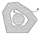
上記ノイズの除去の説明において、図8に示すフローチャートを用いてノイズの除去の工程を詳細に示したが、ノイズの除去の工程は上述のものに限定されるわけではない。図13に示すように、物体要素が他のサイクル状の物体要素内部にある状況を考える。なお、図13には示されていないが、内部の物体要素は「緑」の物体要素G(Green Area)、その外延にサイクル状に存在する物体要素は「青」の物体要素B(Blue Area)であるとする。
[Modification 1]
In the description of the noise removal, the noise removal process is shown in detail using the flowchart shown in FIG. 8, but the noise removal process is not limited to the above-described one. Consider the situation where the object element is inside another cycle-like object element as shown in FIG. Although not shown in FIG. 13, the internal object element is a “green” object element G (Green Area), and the object element that is present in a cycle on the outside is “blue” object element B (Blue Area). ).
このようにある物体要素が別の物体要素のサイクル内に存在する場合、サイクル状の物体要素はノイズであると考えられる。 When one object element exists in the cycle of another object element in this way, the cycle-like object element is considered to be noise.
以下(表5)に、物体要素Gが別の物体要素Bのサイクル内に存在するのか否かを判定する工程を述べる。判定する工程は、図8のフローチャートを構成する各工程間のどこで行われてもよいし、工程S0810の後に行われてもよい。 In the following (Table 5), the step of determining whether or not the object element G exists in the cycle of another object element B will be described. The step of determining may be performed anywhere between the steps constituting the flowchart of FIG. 8 or may be performed after step S0810.
[表5]
BOOL GreenAreaIsInsideBlueArea(AreaElement G, AreaElement B)
{
int i,j;
for (i=0 ; i<Gの線分要素の個数 ; i++)
{
int l[十分大きな整数];
BOOL inside = NO;
int x = G(i(x)); //Gのi番目の線分要素の始点のx座標
int y = G(i(y)); //Gのi番目の線分要素の始点のy座標
int w = G(i(w)); //Gのi番目の線分要素の幅
int c = 0; //y座標が一致する線分要素の数
for (j=0 ; j<Bの線分要素の個数 ; j++)
{
if (y == B(j(y))) //y座標が一致するものがあれば
{
l[c] = j;
c = c+1; //一致しているから数を1プラス
}
}
if (c > 1)
{
BOOL left_exists = NO;BOOL right_exists = NO; //Gの線分要素の左、右にBの線分要素があるか
int k;
for (k=0 ; k<c ; k++) //y座標が同じものについてループ
{
LineElement L = B(l[c]);
if (x + w < L(x))
{
right_exists = YES;
} else if (L(x) + L(w) < x) {
left_exists = YES;
}
}
if (left_exists)
{
if (right_exists)
{
inside = YES;
} else {
inside = NO;
}
} else {
inside = NO;
}
} else {
inside = NO;
}
if (inside == NO)
{
return NO; //左右ともに囲まれていない線分があれば直ちに関数から抜け出してNOを返す
}
}
return YES; //一度もinsideがNOになっていないから、全ての線分要素が左右囲まれているから、物体要素も左右囲まれている。よって、GはBの中にある。
}
[Table 5]
BOOL GreenAreaIsInsideBlueArea (AreaElement G, AreaElement B)
{
int i, j;
for (i = 0; number of line segment elements where i <G; i ++)
{
int l [large enough integer];
BOOL inside = NO;
int x = G (i (x)); // x coordinate of the start point of the i-th line element of G
int y = G (i (y)); // y coordinate of the start point of the i-th line element of G
int w = G (i (w)); // width of i-th line element of G
int c = 0; // number of line elements with matching y coordinates
for (j = 0; number of line segment elements where j <B; j ++)
{
if (y == B (j (y))) // If there is something that matches the y coordinate
{
l [c] = j;
c = c + 1; // Because it matches, add 1 to the number
}
}
if (c> 1)
{
BOOL left_exists = NO; BOOL right_exists = NO; // Does the line segment element of B have left and right sides of the line segment element of G?
int k;
for (k = 0; k <c; k ++) // Loop for the same y coordinate
{
LineElement L = B (l [c]);
if (x + w <L (x))
{
right_exists = YES;
} else if (L (x) + L (w) <x) {
left_exists = YES;
}
}
if (left_exists)
{
if (right_exists)
{
inside = YES;
} else {
inside = NO;
}
} else {
inside = NO;
}
} else {
inside = NO;
}
if (inside == NO)
{
return NO; // If there is a line segment that is not enclosed on either side, immediately exit the function and return NO
}
}
return YES; // Because inside is never set to NO, all line segment elements are surrounded by left and right, so object elements are also surrounded by right and left. So G is in B.
}
ある物体要素が別の物体要素のサイクル内に存在することを数学的に表記すると、以下のようになる。
なお、上記表5に示す、物体要素Gが別の物体要素Bのサイクル内に存在するのか否かを判定する工程は、2次元の物体要素G、Bに関するものである。エレメント指向はn次元(n≧3)の物体要素を対象にできる考え方であるから、あるn次元の物体要素が別のn次元の物体要素のサイクル内に存在するか否かの判定にもエレメント指向の考え方を利用できる。但し、n次元(n≧3)の物体要素のサイクル関係の判定では、2次元の物体要素のサイクル関係の判定(表5参照)よりも考慮すべき点が増大する。 The step of determining whether or not the object element G exists in the cycle of another object element B shown in Table 5 above relates to the two-dimensional object elements G and B. Element-oriented is an idea that can target an n-dimensional (n ≧ 3) object element, so that an element is also used to determine whether a certain n-dimensional object element exists in a cycle of another n-dimensional object element. You can use oriented thinking. However, in the determination of the cycle relationship of n-dimensional (n ≧ 3) object elements, the points to be considered increase compared to the determination of the cycle relationship of two-dimensional object elements (see Table 5).
このように、エレメント指向は、単に物体の代数幾何学的な不連続(性)を表すのに適するだけでなく、物体の位相幾何学的な特徴を表すのにも適する考え方であるといえる。 Thus, element orientation is not only suitable for representing the algebraic discontinuity (gender) of an object, but also an idea suitable for representing the topological features of an object.
[変形例2]
上記マーカ作成部の説明において、マーカ作成の一例を述べたが、マーカ及びシールは上述のものに限定されるわけではない。例えば、親指には赤色のシールを、親指以外の指には黄色のシールを貼り、親指以外の指のシールの鏡像たるマーカは、上述の「対象オブジェクト操作部」の説明で述べたマーカと同じ機能を有し、親指の(赤色の)シールの鏡像たるマーカ(の表示)は、マウスのクリックの機能を有するようにしてもよい。
[Modification 2]
In the description of the marker creation unit, an example of marker creation has been described. However, the marker and the seal are not limited to those described above. For example, a red sticker is applied to the thumb, a yellow sticker is applied to a finger other than the thumb, and the marker that is a mirror image of the seal of the finger other than the thumb is the same as the marker described in the description of the “target object operation unit” above. The marker (display) which has a function and is a mirror image of the thumb (red) seal may have a mouse click function.
つまり、親指を曲げて親指の赤色シールがDVカメラに写らないようにした上で、他の4本の指でウインドウ24を操作し、途中で親指を伸ばして親指の赤色シールがDVカメラに写るようにする(即ち、赤色シールの鏡像たるマーカが突然表示される)とクリック操作が発生する。
In other words, after bending the thumb so that the red sticker on the thumb is not reflected on the DV camera, the
また、左手の親指には赤色のシールを、右手の5本の指には黄色のシールを貼り、右手の指のシールの鏡像たるマーカは、上述の「対象オブジェクト操作部」の説明で述べたマーカと同じ機能を有し、左手親指の(赤色の)シールの鏡像たるマーカの表示は、マウスのクリックの機能を有するものであってもよい。 Also, a red sticker is attached to the thumb of the left hand, a yellow sticker is attached to the five fingers of the right hand, and the marker that is a mirror image of the sticker of the right hand finger is described in the description of the “target object operation unit” above. The display of the marker that has the same function as the marker and is a mirror image of the (red) seal of the left thumb may have a mouse click function.
また、シールがストロー等の短い棒状物の先端に貼られ、操作者がそのストローをくわえ口によりシール及びマーカを動かすようにしてもよい。 Alternatively, a sticker may be attached to the tip of a short rod-like object such as a straw, and the operator may move the sticker and the marker through the mouth with the straw.
タッチスクリーンがマーカの入力源(マーカ情報取得部14)であってもよい。つまり、画面がタッチスクリーンを兼ねており、その画面への圧力を伴う接触による接触領域がマーカとなるようにしてもよい。 The touch screen may be a marker input source (marker information acquisition unit 14). That is, the screen may also serve as a touch screen, and a contact area by contact with pressure on the screen may be a marker.
2・・・オブジェクト操作装置、4・・・表示装置、8・・・コンピュータ、10・・・デジタル撮像装置(DVカメラ)、12・・・シール、14・・・マーカ情報所得部、16・・・マーカ作成部、18・・・マーカ表示部、20・・・対象オブジェクト操作部、22・・・マーカ、24・・・ウインドウ。 2 ... Object operation device, 4 ... Display device, 8 ... Computer, 10 ... Digital imaging device (DV camera), 12 ... Seal, 14 ... Marker information income section, 16. -Marker creation part, 18 ... Marker display part, 20 ... Target object operation part, 22 ... Marker, 24 ... Window.
Claims (15)
演算装置と、
上記演算装置と接続する表示装置と、
上記演算装置と接続する撮像装置と
を備え、
上記撮像装置は所定の操作体を撮像し、上記演算装置は撮像された上記操作体の画像をマーカとして上記表示装置に表示し、
上記マーカの動きにより上記表示装置の画面におけるオブジェクトが操作されるオブジェクト操作装置において、
上記演算装置は、
上記撮像装置が撮像したデジタル画像フレームデータから、所定の色相、彩度若しくは明度を含む画像の持つ特性に着目して画素単位でビットマップB(x,y)を作成し、
上記ビットマップB(x,y)の、各々のy値におけるビットの存在を、始点(x)及び幅(w)による線分要素(x,y,w)で表し、
上記各線分要素の間の接触関係の存否を判断し、接触関係にある線分要素を一まとめにして物体要素とし、
上記物体要素から上記マーカを作成する
ことを特徴とするオブジェクト操作装置。 An object operation device that operates an object in a screen based on an imaged operation body,
An arithmetic unit;
A display device connected to the arithmetic device;
An imaging device connected to the arithmetic device,
The imaging device captures an image of a predetermined operation body, the arithmetic unit displays the captured image of the operation body as a marker on the display device,
In an object operation device in which an object on the screen of the display device is operated by the movement of the marker,
The arithmetic unit is
From the digital image frame data captured by the imaging device, a bitmap B (x, y) is created in pixel units by paying attention to the characteristics of an image including a predetermined hue, saturation, or brightness,
The presence of a bit in each y value of the bitmap B (x, y) is represented by a line segment element (x, y, w) with a start point (x) and a width (w),
Judge the presence or absence of the contact relationship between the above line segment elements, put together the line segment elements in contact relationship as an object element,
Create the marker from the object element
An object operating device characterized by that .
複数の上記操作体による複数の上記マーカを上記ウインドウの内側で互いに接近させると、
上記ウインドウが表示画面の前面にないならば上記ウインドウが前面に移動し、上記ウインドウが表示画面の前面にあるならば上記ウインドウがドラッグされることを特徴とする請求項3に記載のオブジェクト操作装置。 The above object is a window,
When the plurality of markers by the plurality of operating bodies are brought closer to each other inside the window,
4. The object operating device according to claim 3, wherein if the window is not in front of the display screen, the window is moved to the front, and if the window is in front of the display screen, the window is dragged. .
複数の上記操作体による複数の上記マーカを上記ウインドウ外側から上記ウインドウの一辺に接近させると、
上記ウインドウが表示画面の座標軸に平行に移動することを特徴とする請求項3に記載のオブジェクト操作装置。 The above object is a window,
When the plurality of markers by the plurality of operating bodies are brought close to one side of the window from the outside of the window,
4. The object operating device according to claim 3, wherein the window moves in parallel with the coordinate axis of the display screen .
複数の上記操作体による複数の上記マーカのうち、1個以上ずつのマーカを上記ウインドウの一組の対辺の夫々の外側から中心に近づけさせると、
上記ウインドウが、上記一組の対辺の夫々に交差し且つ中心に向かう方向に、縮小することを特徴とする請求項3に記載のオブジェクト操作装置。 The above object is a window,
When one or more markers among the plurality of markers by the plurality of operating bodies are brought closer to the center from the outside of each pair of opposite sides of the window,
4. The object operating device according to claim 3, wherein the window is reduced in a direction crossing each of the pair of opposite sides and moving toward the center .
複数の上記操作体による複数の上記マーカのうち、1個以上ずつのマーカを上記ウインドウの一組の対辺の夫々の内側から、対辺の夫々に接して広げさせると、
上記ウインドウが、上記一組の対辺の夫々に交差し且つ中心から遠ざかる方向に、広がることを特徴とする請求項3に記載のオブジェクト操作装置。 The above object is a window,
Among the plurality of markers by the plurality of operating bodies, when one or more markers are spread from the inside of each pair of opposite sides of the window in contact with each of the opposite sides,
The object operating device according to claim 3, wherein the window extends in a direction that intersects each of the pair of opposite sides and moves away from the center .
3個以上の上記操作体による3個以上の上記マーカのうち、1個以上ずつのマーカを上記ウインドウの3乃至4辺の夫々の外側に接して存在させ且つそれらマーカを同じ速度ベクトルで移動させると、
上記ウインドウが平行に移動することを特徴とする請求項3に記載のオブジェクト操作装置。 The above object is a window,
Among the three or more markers by the three or more operating bodies, one or more markers are present in contact with the outside of each of the three to four sides of the window, and the markers are moved by the same velocity vector. When,
The object operating device according to claim 3, wherein the window moves in parallel .
3個以上の上記操作体による3個以上の上記マーカのうち、1個以上ずつのマーカを上記ウインドウの3乃至4辺の夫々の内側に接して存在させ且つそれらマーカを中心から遠ざかる方向へ移動させると、
マーカの動きに合わせて上記ウインドウの幅及び高さが広がることを特徴とする請求項3に記載のオブジェクト操作装置。 The above object is a window,
Among the three or more markers by the three or more operating bodies, one or more markers are present in contact with the inside of each of the three to four sides of the window, and the markers are moved away from the center. If you let
The object operating device according to claim 3, wherein the width and height of the window increase in accordance with the movement of the marker .
更に、上記演算装置におけるフレームデータの処理において、上記順序に沿って、マーカとオブジェクトとが予め定義された上記関係を満たすか否かが確認され、満たさないことが確認されたときの上記順序付けにおける項数を“k”と置くと、(k−1)番目の上記順序付けに対応する操作内容がマーカからオブジェクトに対する操作となることを特徴とする請求項3に記載のオブジェクト操作装置。 In the arithmetic device, the relationship between the marker and the object is defined in advance for each operation content, and further, the plurality of operation content is ordered in advance from basic operation to complex operation,
Further, in the processing of the frame data in the arithmetic device, it is confirmed whether or not the marker and the object satisfy the predefined relationship in the order, and in the ordering when it is confirmed that the marker and the object do not satisfy the relationship. The object operating device according to claim 3, wherein when the number of terms is set to "k", the operation content corresponding to the (k-1) th ordering is an operation from the marker to the object .
マーカの操作の対象がどのオブジェクトであるかが、上記順番付けに沿って確認されることを特徴とする請求項10に記載のオブジェクト操作装置。 In the processing of the frame data in the arithmetic device, a plurality of objects on the screen of the display device are ordered from the front of the screen to the back of the screen,
The object operating device according to claim 10, wherein the object to be operated by the marker is confirmed along the ordering .
各々のy値におけるビットの存在を、始点(x)及び幅(w)による線分要素(x,y,w)で表す工程と、
上記各線分要素の間の接触関係の存否を判断し、接触関係にある線分要素を一まとめにして物体要素とする工程と、
物体要素のうちからノイズを除去する工程と
を含む、デジタル画像フレームデータからマーカを特定する方法。 A step of creating a bitmap B (x, y) in pixel units by paying attention to characteristics of an image including predetermined hue, saturation, or brightness in digital image frame data;
Expressing the presence of a bit in each y value by a line segment element (x, y, w) with a starting point (x) and a width (w);
Determining the presence or absence of a contact relationship between the line segment elements, and combining the line segment elements in the contact relationship into an object element;
Removing noise from object elements;
A method for identifying a marker from digital image frame data .
デジタル画像フレームデータの画素ごとにRGB値からHSV値に変換してH(Hue;色相)、S(Saturation;彩度)及びV(Value;明度)の値を取得する工程と、
予め設定されているHSV値(H 0 ,S 0 ,V 0 )と、個々の画素(x,y)での上記HSV値を、H、S、V夫々について比較し、夫々の差異が夫々の閾値以下の画素のみマーカ候補部分として抜き出してビットをオンとし、それ以外の画素ではビットをオフとする工程と
を含むことを特徴とする請求項13に記載の方法。 The step of creating the bitmap B (x, y)
Converting RGB values into HSV values for each pixel of the digital image frame data to obtain values of H (Hue; hue), S (Saturation) and V (Value);
The HSV value (H 0 , S 0 , V 0 ) set in advance and the HSV value at each pixel (x, y) are compared for each of H, S, and V, and each difference is different. Extracting only the pixels below the threshold as the marker candidate part and turning on the bits; and turning off the bits in other pixels;
14. The method of claim 13, comprising :
物体要素の面積が、第1の所定値より大きい値のもの、又は第2の所定値より小さい値のものを除去する工程と、
正円率が所定値より低い物体要素を除去する工程と、
数珠状のノイズを除去する工程と、
現在のフレーム上の各物体要素と、記録されている一つ前のフレーム上の各物体要素を対比させて、重心座標が同じ又は重心座標の差異が所定値以下である物体要素同士を、同じ物体要素として結び付ける工程と、
直前の一つ又は数枚のフレームと現在のフレームとにおける同一物体要素の重心座標の差異から、各物体要素の速度ベクトルを求める工程と
を含むことを特徴とする請求項13に記載の方法。 Removing noise from the object elements,
Removing the object element having an area larger than the first predetermined value or a value smaller than the second predetermined value;
Removing object elements having a circularity ratio lower than a predetermined value;
Removing beaded noise;
By comparing each object element on the current frame with each object element on the previous recorded frame, the object elements with the same center of gravity coordinates or the difference of the center of gravity coordinates being equal to or less than a predetermined value are the same. Linking as an object element;
Obtaining a velocity vector of each object element from a difference in barycentric coordinates of the same object element between the immediately preceding frame or frames and the current frame;
14. The method of claim 13, comprising :
Priority Applications (2)
| Application Number | Priority Date | Filing Date | Title |
|---|---|---|---|
| JP2007271491A JP4938617B2 (en) | 2007-10-18 | 2007-10-18 | Object operating device and method for specifying marker from digital image frame data |
| US12/285,937 US8232964B2 (en) | 2007-10-18 | 2008-10-16 | Apparatus for operating objects and a method for identifying markers from digital image frame data |
Applications Claiming Priority (1)
| Application Number | Priority Date | Filing Date | Title |
|---|---|---|---|
| JP2007271491A JP4938617B2 (en) | 2007-10-18 | 2007-10-18 | Object operating device and method for specifying marker from digital image frame data |
Publications (3)
| Publication Number | Publication Date |
|---|---|
| JP2009099042A JP2009099042A (en) | 2009-05-07 |
| JP2009099042A5 JP2009099042A5 (en) | 2010-12-24 |
| JP4938617B2 true JP4938617B2 (en) | 2012-05-23 |
Family
ID=40623260
Family Applications (1)
| Application Number | Title | Priority Date | Filing Date |
|---|---|---|---|
| JP2007271491A Expired - Fee Related JP4938617B2 (en) | 2007-10-18 | 2007-10-18 | Object operating device and method for specifying marker from digital image frame data |
Country Status (2)
| Country | Link |
|---|---|
| US (1) | US8232964B2 (en) |
| JP (1) | JP4938617B2 (en) |
Families Citing this family (5)
| Publication number | Priority date | Publication date | Assignee | Title |
|---|---|---|---|---|
| GB2479896A (en) * | 2010-04-28 | 2011-11-02 | Peekabu Studios Ltd | User generated control signals using fiducial markers associated with the user |
| KR101558200B1 (en) * | 2010-12-06 | 2015-10-08 | 한국전자통신연구원 | Apparatus and method for controlling idle of vehicle |
| CN103135755B (en) * | 2011-12-02 | 2016-04-06 | 深圳泰山在线科技有限公司 | Interactive system and method |
| KR20130072638A (en) * | 2011-12-22 | 2013-07-02 | 엘지전자 주식회사 | Method for operating an image display apparatus |
| KR20150110032A (en) * | 2014-03-24 | 2015-10-02 | 삼성전자주식회사 | Electronic Apparatus and Method for Image Data Processing |
Family Cites Families (20)
| Publication number | Priority date | Publication date | Assignee | Title |
|---|---|---|---|---|
| JPS6295686A (en) * | 1985-10-21 | 1987-05-02 | Sumitomo Electric Ind Ltd | Segment approximating method for ridgeline of object in picture |
| JPH07182101A (en) * | 1993-10-26 | 1995-07-21 | Itu Res Inc | Apparatus and method for input of graphic, operating method of graphic object and supply method of graphic input signal |
| DE69626208T2 (en) * | 1996-12-20 | 2003-11-13 | Hitachi Europ Ltd | Method and system for recognizing hand gestures |
| US6160923A (en) * | 1997-11-05 | 2000-12-12 | Microsoft Corporation | User directed dust and compact anomaly remover from digital images |
| EP2264671B1 (en) * | 1998-04-07 | 2016-02-10 | Omron Corporation | Image processing apparatus and method, medium storing program for image processing, and inspection apparatus |
| JP2000105671A (en) | 1998-05-11 | 2000-04-11 | Ricoh Co Ltd | Coordinate input and detecting device, and electronic blackboard system |
| JP4033582B2 (en) | 1998-06-09 | 2008-01-16 | 株式会社リコー | Coordinate input / detection device and electronic blackboard system |
| JP3641942B2 (en) * | 1998-06-24 | 2005-04-27 | 松下電工株式会社 | Line group pattern recognition method |
| JP3863809B2 (en) * | 2002-05-28 | 2006-12-27 | 独立行政法人科学技術振興機構 | Input system by hand image recognition |
| JP2004038429A (en) | 2002-07-02 | 2004-02-05 | Nippon Telegr & Teleph Corp <Ntt> | System, method and program for composite image display, and recording medium with program recorded thereon |
| JP2004078488A (en) | 2002-08-15 | 2004-03-11 | Advanced Telecommunication Research Institute International | Virtual desktop system |
| JP4306256B2 (en) * | 2003-01-16 | 2009-07-29 | ソニー株式会社 | Motion vector detection device, motion vector detection method, program, and recording medium |
| JP2004240672A (en) * | 2003-02-05 | 2004-08-26 | Minolta Co Ltd | Image edit program |
| JP3953450B2 (en) * | 2003-09-05 | 2007-08-08 | 日本電信電話株式会社 | 3D object posture operation method and program |
| JP4429047B2 (en) * | 2004-03-11 | 2010-03-10 | キヤノン株式会社 | Coordinate input device, control method therefor, and program |
| JP2005301693A (en) | 2004-04-12 | 2005-10-27 | Japan Science & Technology Agency | Animation editing system |
| JP4575829B2 (en) | 2005-03-30 | 2010-11-04 | 財団法人エヌエイチケイエンジニアリングサービス | Display screen position analysis device and display screen position analysis program |
| US7538894B2 (en) * | 2005-04-15 | 2009-05-26 | Canon Kabushiki Kaisha | Coordinate input apparatus, control method thereof, and program |
| US8345047B2 (en) * | 2007-05-30 | 2013-01-01 | Deere & Company | Method for displaying performance information for one or more vehicles |
| US8726194B2 (en) * | 2007-07-27 | 2014-05-13 | Qualcomm Incorporated | Item selection using enhanced control |
-
2007
- 2007-10-18 JP JP2007271491A patent/JP4938617B2/en not_active Expired - Fee Related
-
2008
- 2008-10-16 US US12/285,937 patent/US8232964B2/en not_active Expired - Fee Related
Also Published As
| Publication number | Publication date |
|---|---|
| US20090122010A1 (en) | 2009-05-14 |
| JP2009099042A (en) | 2009-05-07 |
| US8232964B2 (en) | 2012-07-31 |
Similar Documents
| Publication | Publication Date | Title |
|---|---|---|
| Shriram et al. | Deep learning-based real-time AI virtual mouse system using computer vision to avoid COVID-19 spread | |
| JP6079832B2 (en) | Human computer interaction system, hand-to-hand pointing point positioning method, and finger gesture determination method | |
| Zhou et al. | A novel finger and hand pose estimation technique for real-time hand gesture recognition | |
| US20200066047A1 (en) | Gestures for Facilitating Interaction with Pages in a Mixed Reality Environment | |
| JP6323040B2 (en) | Image processing apparatus, image processing method, and program | |
| US10078796B2 (en) | Apparatus and method of hand gesture recognition based on depth image | |
| US20140123077A1 (en) | System and method for user interaction and control of electronic devices | |
| JP4938617B2 (en) | Object operating device and method for specifying marker from digital image frame data | |
| Badi et al. | Hand posture and gesture recognition technology | |
| Jalab et al. | Human computer interface using hand gesture recognition based on neural network | |
| WO2013051681A1 (en) | Finger shape estimation device, finger shape estimation method, and finger shape estimation program | |
| Barsoum | Articulated hand pose estimation review | |
| Ma et al. | Real-time and robust hand tracking with a single depth camera | |
| Chowdhury et al. | Gesture recognition based virtual mouse and keyboard | |
| Shah et al. | Hand gesture based user interface for computer using a camera and projector | |
| JP6651388B2 (en) | Gesture modeling device, gesture modeling method, program for gesture modeling system, and gesture modeling system | |
| Titlee et al. | A novel design of an intangible hand gesture controlled computer mouse using vision based image processing | |
| Ghodichor et al. | Virtual mouse using hand gesture and color detection | |
| JP6425299B2 (en) | Finger motion detection device, finger motion detection method, finger motion detection program, and virtual object processing system | |
| Fujiwara et al. | Interactions with a line-follower: An interactive tabletop system with a markerless gesture interface for robot control | |
| Mazumder et al. | Finger gesture detection and application using hue saturation value | |
| Jain et al. | Human computer interaction–Hand gesture recognition | |
| JP2014038543A (en) | Character recognition system and program for recognizing finger character | |
| Shin et al. | Deep Learning-based Hand Pose Estimation from 2D Image | |
| Xie et al. | Hand posture recognition using kinect |
Legal Events
| Date | Code | Title | Description |
|---|---|---|---|
| A521 | Request for written amendment filed |
Free format text: JAPANESE INTERMEDIATE CODE: A523 Effective date: 20101018 |
|
| A621 | Written request for application examination |
Free format text: JAPANESE INTERMEDIATE CODE: A621 Effective date: 20101018 |
|
| A711 | Notification of change in applicant |
Free format text: JAPANESE INTERMEDIATE CODE: A711 Effective date: 20101018 |
|
| A521 | Request for written amendment filed |
Free format text: JAPANESE INTERMEDIATE CODE: A821 Effective date: 20101018 |
|
| A977 | Report on retrieval |
Free format text: JAPANESE INTERMEDIATE CODE: A971007 Effective date: 20111213 |
|
| TRDD | Decision of grant or rejection written | ||
| A01 | Written decision to grant a patent or to grant a registration (utility model) |
Free format text: JAPANESE INTERMEDIATE CODE: A01 Effective date: 20120117 |
|
| A01 | Written decision to grant a patent or to grant a registration (utility model) |
Free format text: JAPANESE INTERMEDIATE CODE: A01 |
|
| FPAY | Renewal fee payment (event date is renewal date of database) |
Free format text: PAYMENT UNTIL: 20150302 |
|
| R150 | Certificate of patent or registration of utility model |
Free format text: JAPANESE INTERMEDIATE CODE: R150 |
|
| FPAY | Renewal fee payment (event date is renewal date of database) |
Free format text: PAYMENT UNTIL: 20150302 Year of fee payment: 3 |
|
| R150 | Certificate of patent or registration of utility model |
Free format text: JAPANESE INTERMEDIATE CODE: R150 |
|
| FPAY | Renewal fee payment (event date is renewal date of database) |
Free format text: PAYMENT UNTIL: 20150302 Year of fee payment: 3 |
|
| R250 | Receipt of annual fees |
Free format text: JAPANESE INTERMEDIATE CODE: R250 |
|
| LAPS | Cancellation because of no payment of annual fees |