JP4938538B2 - Powder slush molding equipment - Google Patents
Powder slush molding equipment Download PDFInfo
- Publication number
- JP4938538B2 JP4938538B2 JP2007113381A JP2007113381A JP4938538B2 JP 4938538 B2 JP4938538 B2 JP 4938538B2 JP 2007113381 A JP2007113381 A JP 2007113381A JP 2007113381 A JP2007113381 A JP 2007113381A JP 4938538 B2 JP4938538 B2 JP 4938538B2
- Authority
- JP
- Japan
- Prior art keywords
- reservoir container
- air hole
- mold
- powder material
- air filter
- Prior art date
- Legal status (The legal status is an assumption and is not a legal conclusion. Google has not performed a legal analysis and makes no representation as to the accuracy of the status listed.)
- Expired - Fee Related
Links
- 239000000843 powder Substances 0.000 title claims abstract description 70
- 238000000465 moulding Methods 0.000 title claims abstract description 33
- 239000000463 material Substances 0.000 claims abstract description 43
- 239000003566 sealing material Substances 0.000 description 9
- 238000012423 maintenance Methods 0.000 description 5
- 238000007789 sealing Methods 0.000 description 4
- 230000002093 peripheral effect Effects 0.000 description 3
- 230000002411 adverse Effects 0.000 description 2
- 230000000694 effects Effects 0.000 description 2
- 238000004891 communication Methods 0.000 description 1
- 230000001788 irregular Effects 0.000 description 1
- 238000012986 modification Methods 0.000 description 1
- 230000004048 modification Effects 0.000 description 1
Images



Landscapes
- Moulds For Moulding Plastics Or The Like (AREA)
- Moulding By Coating Moulds (AREA)
Abstract
Description
この発明は、パウダースラッシュ成形装置に関するものである。 The present invention relates to a powder slush molding apparatus.
自動車などの車両には、車室内の前部にインストルメントパネルなどの内装パネルが設けられている。このような内装パネルには、パウダースラッシュ成形装置(例えば、特許文献1参照)で成形した表皮材(いわゆるパウダースラッシュ表皮)などを有するものが存在する。 A vehicle such as an automobile is provided with an interior panel such as an instrument panel in the front part of the vehicle interior. Some of such interior panels have a skin material (so-called powder slush skin) formed by a powder slush molding device (see, for example, Patent Document 1).
特許文献1のパウダースラッシュ成形装置1は、要するに、図4に示すように、粉体材料2を収容可能なリザーバ容器3の開口縁部4に対し、250度〜300度などの高温に加熱した金型5を、シール材6を介してシール状態で被着し、リザーバ容器3と金型5とを回転軸7を中心として回転させることにより、金型5に粉体材料2を溶融付着させて成形を行うようにしたものである。図中、符号8はパウダースラッシュ成形装置1によって得られる成形品(パウダースラッシュ表皮)を示している。
In short, the powder
このパウダースラッシュ成形装置1では、リザーバ容器3に空気孔11が設けられ、空気孔11にエアフィルター12が取付けられている。この場合、空気孔11は、リザーバ容器3の回転軸7とほぼ平行な側面13(或いは回転軸7と交差しない側面13)に設けられ、エアフィルター12は、リザーバ容器3の外側(空気孔11の外方端側)に取付けられている。
In the powder
このような構成において、リザーバ容器3の開口縁部4に、加熱した金型5をシール状態で被着すると、金型5の熱によってリザーバ容器3内の空気が熱膨張し、熱膨張に伴う内圧の上昇によってシール材6と金型5とのシール面がズレて、シール材6に悪影響を及ぼしたり、糸引現象を発生したりする原因となるおそれがある。
In such a configuration, when the
そこで、リザーバ容器3に空気孔11を設け、この空気孔11から熱膨張分の空気を逃がすことにより、シール面のズレを防止して、シール材6の保護や糸引現象の低減を図るようにしている。この際、空気孔11にエアフィルター12を取付けることによって、粉体材料2が外部へ出て行くことのないようにしている。なお、上記以外の詳細事項については、特許文献1を参照のこと。
しかしながら、上記特許文献1に記載されたパウダースラッシュ成形装置1では、空気孔11を、リザーバ容器3の回転軸7とほぼ平行な側面13に設けるようにしていたため、リザーバ容器3が1回転する間に、粉体材料2が空気孔11へ向けて最低1回はナダレ込むこととなるので、エアフィルター12がリザーバ容器3の内側に取付けられていると、エアフィルター12がすぐに目詰まりを起こしてしまう。エアフィルター12のメンテナンスは、パウダースラッシュ成形装置1の運転を停止して行う大掛かりな作業となると共に、生産性が低下するため、極力少なくすることが望まれる。
However, in the powder
そこで、特許文献1では、エアフィルター12の取付位置を、リザーバ容器3の内側から外側へと変更することにより、エアフィルター12の目詰まりが起こり難くなるようにしてメンテナンス回数を削減させるようにしていた。
Therefore, in
しかし、エアフィルター12を、リザーバ容器3の外側に取付けると、パウダースラッシュ成形装置1の高温の回転部分(リザーバ容器3および金型5など)の回転半径が大きくなってしまう。高温の回転部分の回転半径が大きくなると、装置全体が大型化すると共に、工場内の要注意領域が拡大するので、好ましくない。
However, if the
上記課題を解決するために、請求項1に記載された発明では、粉体材料を収容可能なリザーバ容器の開口縁部に、加熱した金型をシール状態で被着し、リザーバ容器と金型とを回転させることにより、金型の表面に粉体材料を溶融付着させて成形を行うようにしたパウダースラッシュ成形装置において、リザーバ容器に空気孔が設けられ、空気孔にエアフィルターが取付けられると共に、空気孔が、リザーバ容器の回転中心と交差する側面における、回転によって粉体材料が滞らない位置に形成され、エアフィルターが、空気孔の内方端側に取付けられたパウダースラッシュ成形装置を特徴としている。
In order to solve the above-described problem, in the invention described in
請求項1の発明によれば、粉体材料を収容可能なリザーバ容器の開口縁部に、加熱した金型をシール状態で被着し、リザーバ容器と金型とを回転させることにより、金型の表面に粉体材料を溶融付着させて成形を行うようにしたパウダースラッシュ成形装置において、リザーバ容器に空気孔が設けられ、空気孔にエアフィルターが取付けられると共に、空気孔が、リザーバ容器の回転中心と交差する側面における、回転によって粉体材料が滞らない位置に形成され、エアフィルターが、空気孔の内方端側に取付けられたことにより、以下のような作用効果を得ることができる。即ち、リザーバ容器に設けた空気孔から、加熱された金型による熱膨張分の空気を逃がすことにより、シール面のズレを防止して、シール材の保護や糸引現象の低減を図ることができる。そして、空気孔にエアフィルターを取付けることによって、粉体材料が外部へ出て行かないようにすることができる。この際、空気孔が、リザーバ容器の回転中心と交差する側面における、回転によって粉体材料が滞らない位置に形成されたことにより、リザーバ容器の回転によって粉体材料が空気孔へ向けてナダレ込むようなことがなくなるので、エアフィルターを空気孔の内方端側に取付けても、エアフィルターの目詰まりを防止・低減することができる。これにより、エアフィルターのメンテナンス回数を削減してエアフィルターの長寿命化や生産性の向上などを図ると共に、パウダースラッシュ成形装置の高温の回転部分(リザーバ容器および金型など)の回転半径を小さくして装置全体の小型化や工場内の要注意領域の縮小などを得ることが可能となる。 According to the first aspect of the present invention, the heated mold is attached in a sealed state to the opening edge of the reservoir container capable of accommodating the powder material, and the mold is obtained by rotating the reservoir container and the mold. In a powder slush molding device in which powder material is melted and adhered to the surface of the container, an air hole is provided in the reservoir container, an air filter is attached to the air hole, and the air hole is rotated by the reservoir container. Since the powder material is formed on the side surface intersecting the center at a position where the powder material does not stagnate by rotation, and the air filter is attached to the inner end side of the air hole, the following effects can be obtained. That is, by releasing the air corresponding to the thermal expansion caused by the heated mold from the air holes provided in the reservoir container, it is possible to prevent the sealing surface from being displaced, thereby protecting the sealing material and reducing the stringing phenomenon. . By attaching an air filter to the air hole, the powder material can be prevented from going outside. At this time, since the air hole is formed at a position where the powder material does not stagnate due to the rotation on the side surface intersecting the rotation center of the reservoir container, the powder material droops toward the air hole by the rotation of the reservoir container. Therefore, even if the air filter is attached to the inner end side of the air hole, clogging of the air filter can be prevented / reduced. As a result, the number of maintenance of the air filter is reduced to extend the life of the air filter and improve productivity, and the rotation radius of the high-temperature rotating part (reservoir container and mold, etc.) of the powder slush molding device is reduced. As a result, it is possible to reduce the size of the entire apparatus, reduce the area requiring attention in the factory, and the like.
以下、本発明を具体化した実施例について、図示例と共に説明する。 Hereinafter, embodiments embodying the present invention will be described together with illustrated examples.
図1〜図3は、この発明の実施例を示すものである。 1 to 3 show an embodiment of the present invention.
なお、パウダースラッシュ成形装置の構成については、図4を用いて説明したものと基本的にほぼ同様なので、必要に応じてこれらの図面を参照すると共に、これらに対する記載を以てこの実施例の説明とすることができる。この際、同一ないし均等な部分については、同一の符号を付すようにしている。但し、パウダースラッシュ成形装置については、上記に限るものではない。また、異なる部分の構成については、図1〜図3によるものとする。 The configuration of the powder slush molding apparatus is basically almost the same as that described with reference to FIG. 4. Therefore, the drawings will be referred to as necessary and the description of this embodiment will be made with reference thereto. be able to. At this time, the same or equivalent parts are denoted by the same reference numerals. However, the powder slush molding device is not limited to the above. Moreover, about the structure of a different part, it shall be based on FIGS. 1-3.
まず、構成について説明する。 First, the configuration will be described.
自動車などの車両には、車室内の前部にインストルメントパネルなどの内装パネルが設けられている。このような内装パネルには、パウダースラッシュ成形装置で成形した表皮材(いわゆるパウダースラッシュ表皮)などを有するものが存在する。 A vehicle such as an automobile is provided with an interior panel such as an instrument panel in the front part of the vehicle interior. Such interior panels include those having a skin material (so-called powder slush skin) formed by a powder slush molding device.
このようなパウダースラッシュ成形装置1は、図4に示すように、粉体材料2を収容可能なリザーバ容器3の開口縁部4に対し、250度〜300度などの高温に加熱した金型5を、シール材6を介してシール状態で被着し、リザーバ容器3と金型5とを回転軸7を中心として回転させることにより、金型5に粉体材料2を溶融付着させて成形を行うようにしたものである。なお、図4中、符号8はパウダースラッシュ成形装置1によって得られる成形品(パウダースラッシュ表皮)を示している。
As shown in FIG. 4, the powder
このパウダースラッシュ成形装置1では、リザーバ容器3に空気孔11が設けられ、空気孔11にエアフィルター12が取付けられる。
In the powder
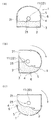
そして、以上のような基本構成に対し、この実施例のものでは、図1に示すように、空気孔11は、リザーバ容器3の回転中心(回転軸7)と交差する側面21に設けられる(交差面側空気孔22)。
And in the thing of this Example with respect to the above basic structures, as shown in FIG. 1, the
なお、図1は、本発明にかかるリザーバ容器3を示すものであり、図4のものとは、形状や構成などが若干異なっている。本発明にかかるリザーバ容器3は、金型5が載置された状態で、図示しない外部の枠体によって挟着保持されるようになっており、しかも、回転軸7はこの枠体に設定されるため、リザーバ容器3には、回転軸7が直接設置されない。即ち、回転軸7は、図1には図示されない。
FIG. 1 shows a
この空気孔11(交差面側空気孔22)は、リザーバ容器3の回転中心と交差する側面21における、回転によって粉体材料2が滞らない位置に形成される。
This air hole 11 (intersection surface side air hole 22) is formed at a position where the
この回転によって粉体材料2が滞らない位置23は、リザーバ容器3や金型5の形状などによってかなり異なったものとなる。この位置23は、例えば、図2(a)〜(c)などに示すように、リザーバ容器3を回転させて粉体材料2の流れをシミュレーションしたり、粉体材料2の安息角などに基づいて計算を行うなどによって設定する。なお、リザーバ容器3を回転させると側面21に粉体材料2の跡がうっすらと残ることから、上記位置23は、比較的容易に割出すことができる。この位置23は、例えば、リザーバ容器3や金型5の形状が整っている場合には、回転中心やその近傍などとなるが、上記形状がいびつであるような場合には、回転中心から離れることとなる。
The
そして、エアフィルター12が、空気孔11の内方端側に取付けられる(内側フィルタ25)。
And the
この場合、図3に示すように、エアフィルター12(内側フィルタ25)は、リザーバ容器3の内部に配置されると共に、空気孔11の内方端に、ボルト26とナット27などの締結固定具を用いて直接取付けられる。この際、リザーバ容器3の上記側面21における空気孔11外方端部には、必要に応じて、空気孔11と同径の孔部28を有するリング状の受板29が介在されて、共締めされる。更に、ボルト26とナット27との螺着部には、緩み止めが塗布される。
In this case, as shown in FIG. 3, the air filter 12 (inner filter 25) is disposed inside the
このエアフィルター12は、例えば、ほぼ円筒形状を呈して、外周側から内周側へとエアを通過させつつ粉体材料2などを分離除去させるようにしたものなどとされる。エアフィルター12の内周部は、空気孔11とほぼ同径の空間とされる。エアフィルター12は、その内端部が閉口されると共に、外端部が開口され、この開口された外端部が、空気孔11の内方端に対し連通状態で配置される。
The
次に、この実施例の作用について説明する。 Next, the operation of this embodiment will be described.
パウダースラッシュ成形装置1では、粉体材料2を収容可能なリザーバ容器3の開口縁部4に対し、250度〜300度などの高温に加熱した金型5を、シール材6を介してシール状態で被着し、リザーバ容器3と金型5とを回転軸7を中心として回転させることにより、金型5に粉体材料2を溶融付着させて成形を行うようにする。
In the powder
この際、リザーバ容器3の開口縁部4に、加熱した金型5をシール状態で被着すると、金型5の熱によってリザーバ容器3内の空気が熱膨張し、熱膨張に伴う内圧の上昇によってシール材6と金型5とのシール面がズレて、シール材6に悪影響を及ぼしたり、糸引現象を発生する原因となったりするおそれがある。
At this time, if the
そこで、リザーバ容器3に空気孔11を設け、空気孔11から熱膨張分の空気を逃がすことにより、シール面のズレを防止して、シール材6の保護や糸引現象の低減を図るようにする。この際、空気孔11にエアフィルター12を取付けることによって、粉体材料2が外部へ出て行くことのないようにする。
Therefore, the
この実施例によれば、粉体材料2を収容可能なリザーバ容器3の開口縁部4に、加熱した金型5をシール状態で被着し、リザーバ容器3と金型5とを回転させることにより、金型5の表面に粉体材料2を溶融付着させて成形を行うようにしたパウダースラッシュ成形装置1において、リザーバ容器3に空気孔11が設けられ、空気孔11にエアフィルター12が取付けられると共に、空気孔11が、リザーバ容器3の回転中心と交差する側面21における、回転によって粉体材料2が滞らない位置23に形成され、エアフィルター12が、空気孔11の内方端側に取付けられたことにより、以下のような作用効果を得ることができる。
According to this embodiment, the
即ち、空気孔11が、リザーバ容器3の回転中心と交差する側面21における、回転によって粉体材料2が滞らない位置23に形成されたことにより、リザーバ容器3の回転によって粉体材料2が空気孔11へ向けてナダレ込むようなことがなくなるので、エアフィルター12を空気孔11の内方端側に取付けても、エアフィルター12の目詰まりを防止・低減することができる。
That is, the
これにより、エアフィルター12のメンテナンス回数を削減してエアフィルター12の長寿命化や生産性の向上などを図ると共に、パウダースラッシュ成形装置1の高温の回転部分(リザーバ容器3および金型5など)の回転半径を小さくして装置全体の小型化や工場内の要注意領域の縮小などを得ることが可能となる。
As a result, the number of maintenance of the
以上、この発明の実施例を図面により詳述してきたが、実施例はこの発明の例示にしか過ぎないものであるため、この発明は実施例の構成にのみ限定されるものではなく、この発明の要旨を逸脱しない範囲の設計の変更等があってもこの発明に含まれることは勿論である。また、例えば、各実施例に複数の構成が含まれている場合には、特に記載がなくとも、これらの構成の可能な組合せが含まれることは勿論である。また、複数の実施例や変形例が示されている場合には、特に記載がなくとも、これらに跨がった構成の組合せのうちの可能なものが含まれることは勿論である。また、図面に描かれている構成については、特に記載がなくとも、含まれることは勿論である。 Although the embodiments of the present invention have been described in detail with reference to the drawings, the embodiments are only examples of the present invention, and the present invention is not limited to the configurations of the embodiments. Needless to say, design changes and the like within a range not departing from the gist of the invention are included in the present invention. Further, for example, when each embodiment includes a plurality of configurations, it is a matter of course that possible combinations of these configurations are included even if not specifically described. Further, when a plurality of embodiments and modifications are shown, it is needless to say that possible combinations of configurations extending over these are included even if not specifically described. Further, the configuration depicted in the drawings is of course included even if not particularly described.
1 パウダースラッシュ成形装置
2 粉体材料
3 リザーバ容器
4 開口縁部
5 金型
7 回転中心(回転軸)
11 空気孔
12 エアフィルター
21 回転中心と交差する側面
23 回転によって粉体材料が滞らない位置
DESCRIPTION OF
Claims (1)
リザーバ容器に空気孔が設けられ、空気孔にエアフィルターが取付けられると共に、
空気孔が、リザーバ容器の回転中心と交差する側面における、回転によって粉体材料が滞らない位置に形成され、
エアフィルターが、空気孔の内方端側に取付けられたことを特徴とするパウダースラッシュ成形装置。 At the opening edge of the reservoir container that can store the powder material, a heated mold is attached in a sealed state, and the reservoir material and the mold are rotated to melt and adhere the powder material to the surface of the mold. In a powder slush molding device that is designed to perform molding,
An air hole is provided in the reservoir container, an air filter is attached to the air hole,
An air hole is formed at a position where the powder material does not stagnate by rotation on the side surface intersecting the rotation center of the reservoir container,
A powder slush molding device, wherein an air filter is attached to an inner end side of an air hole.
Priority Applications (1)
| Application Number | Priority Date | Filing Date | Title |
|---|---|---|---|
| JP2007113381A JP4938538B2 (en) | 2007-04-23 | 2007-04-23 | Powder slush molding equipment |
Applications Claiming Priority (1)
| Application Number | Priority Date | Filing Date | Title |
|---|---|---|---|
| JP2007113381A JP4938538B2 (en) | 2007-04-23 | 2007-04-23 | Powder slush molding equipment |
Publications (2)
| Publication Number | Publication Date |
|---|---|
| JP2008265208A JP2008265208A (en) | 2008-11-06 |
| JP4938538B2 true JP4938538B2 (en) | 2012-05-23 |
Family
ID=40045406
Family Applications (1)
| Application Number | Title | Priority Date | Filing Date |
|---|---|---|---|
| JP2007113381A Expired - Fee Related JP4938538B2 (en) | 2007-04-23 | 2007-04-23 | Powder slush molding equipment |
Country Status (1)
| Country | Link |
|---|---|
| JP (1) | JP4938538B2 (en) |
Family Cites Families (3)
| Publication number | Priority date | Publication date | Assignee | Title |
|---|---|---|---|---|
| JP2514242B2 (en) * | 1988-11-16 | 1996-07-10 | 本田技研工業株式会社 | Powder-slush molding method and molding equipment |
| JPH05169473A (en) * | 1991-12-25 | 1993-07-09 | Tokai Chem Ind Ltd | Powder slush molding apparatus |
| JP4247530B2 (en) * | 2003-07-24 | 2009-04-02 | 株式会社イノアックコーポレーション | Mold vacuum structure |
-
2007
- 2007-04-23 JP JP2007113381A patent/JP4938538B2/en not_active Expired - Fee Related
Also Published As
| Publication number | Publication date |
|---|---|
| JP2008265208A (en) | 2008-11-06 |
Similar Documents
| Publication | Publication Date | Title |
|---|---|---|
| CN102403475A (en) | Battery package and electric vehicle equipped with the battery package | |
| US9541960B2 (en) | Device arrangement | |
| CN202452239U (en) | LED (Light-Emitting Diode) illuminating device | |
| BRPI1101850A2 (en) | cooling fan module, and engine cooling system | |
| JP4938538B2 (en) | Powder slush molding equipment | |
| JP2011241863A (en) | Case, reduction gear, and motor with reduction gear | |
| CN109686896A (en) | A kind of explosion-proof valve | |
| CN209357809U (en) | Explosion-proof vent valve | |
| JP6982187B2 (en) | Spray assembly and agricultural plant protector | |
| CN205207671U (en) | Two joint strip's oil tank port lid | |
| CN104503554B (en) | A kind of notebook fan and its installation method | |
| CA2584237A1 (en) | Ventilation device for enabling a gas transfer via a wall of a housing | |
| CN114506082B (en) | Wind field system for 3D printing | |
| US5270905A (en) | Ceiling fan globe gasket | |
| JP4576753B2 (en) | Centrifugal potting device and method for producing hollow fiber membrane module using the same | |
| JP2003320685A5 (en) | ||
| CN223315255U (en) | Unmanned aerial vehicle rotating vane protection component | |
| JP2008192750A (en) | Housing structure of outdoor equipment | |
| CN204213675U (en) | LED light set with transparent protective cover | |
| CN206317042U (en) | A kind of lid screw container | |
| CN206793957U (en) | Fluid micro injection apparatus | |
| CN215279878U (en) | MIM metal sintering tool | |
| CN215862348U (en) | Mechanized tuber pipe gasket | |
| CN222601176U (en) | Power battery pack and vehicle | |
| CN215167296U (en) | Energy-saving cold channel skylight control system |
Legal Events
| Date | Code | Title | Description |
|---|---|---|---|
| A621 | Written request for application examination |
Free format text: JAPANESE INTERMEDIATE CODE: A621 Effective date: 20091210 |
|
| A977 | Report on retrieval |
Free format text: JAPANESE INTERMEDIATE CODE: A971007 Effective date: 20120213 |
|
| TRDD | Decision of grant or rejection written | ||
| A01 | Written decision to grant a patent or to grant a registration (utility model) |
Free format text: JAPANESE INTERMEDIATE CODE: A01 Effective date: 20120221 |
|
| A01 | Written decision to grant a patent or to grant a registration (utility model) |
Free format text: JAPANESE INTERMEDIATE CODE: A01 |
|
| A61 | First payment of annual fees (during grant procedure) |
Free format text: JAPANESE INTERMEDIATE CODE: A61 Effective date: 20120223 |
|
| FPAY | Renewal fee payment (event date is renewal date of database) |
Free format text: PAYMENT UNTIL: 20150302 Year of fee payment: 3 |
|
| R150 | Certificate of patent or registration of utility model |
Ref document number: 4938538 Country of ref document: JP Free format text: JAPANESE INTERMEDIATE CODE: R150 Free format text: JAPANESE INTERMEDIATE CODE: R150 |
|
| R250 | Receipt of annual fees |
Free format text: JAPANESE INTERMEDIATE CODE: R250 |
|
| R250 | Receipt of annual fees |
Free format text: JAPANESE INTERMEDIATE CODE: R250 |
|
| R250 | Receipt of annual fees |
Free format text: JAPANESE INTERMEDIATE CODE: R250 |
|
| R250 | Receipt of annual fees |
Free format text: JAPANESE INTERMEDIATE CODE: R250 |
|
| LAPS | Cancellation because of no payment of annual fees |