JP4938155B2 - Transverse induction heating device - Google Patents
Transverse induction heating device Download PDFInfo
- Publication number
- JP4938155B2 JP4938155B2 JP2011527919A JP2011527919A JP4938155B2 JP 4938155 B2 JP4938155 B2 JP 4938155B2 JP 2011527919 A JP2011527919 A JP 2011527919A JP 2011527919 A JP2011527919 A JP 2011527919A JP 4938155 B2 JP4938155 B2 JP 4938155B2
- Authority
- JP
- Japan
- Prior art keywords
- plate
- soft magnetic
- induction heating
- shielding
- shielding plate
- Prior art date
- Legal status (The legal status is an assumption and is not a legal conclusion. Google has not performed a legal analysis and makes no representation as to the accuracy of the status listed.)
- Active
Links
Images


Classifications
-
- H—ELECTRICITY
- H05—ELECTRIC TECHNIQUES NOT OTHERWISE PROVIDED FOR
- H05B—ELECTRIC HEATING; ELECTRIC LIGHT SOURCES NOT OTHERWISE PROVIDED FOR; CIRCUIT ARRANGEMENTS FOR ELECTRIC LIGHT SOURCES, IN GENERAL
- H05B6/00—Heating by electric, magnetic or electromagnetic fields
- H05B6/02—Induction heating
- H05B6/10—Induction heating apparatus, other than furnaces, for specific applications
- H05B6/101—Induction heating apparatus, other than furnaces, for specific applications for local heating of metal pieces
- H05B6/103—Induction heating apparatus, other than furnaces, for specific applications for local heating of metal pieces multiple metal pieces successively being moved close to the inductor
- H05B6/104—Induction heating apparatus, other than furnaces, for specific applications for local heating of metal pieces multiple metal pieces successively being moved close to the inductor metal pieces being elongated like wires or bands
-
- H—ELECTRICITY
- H05—ELECTRIC TECHNIQUES NOT OTHERWISE PROVIDED FOR
- H05B—ELECTRIC HEATING; ELECTRIC LIGHT SOURCES NOT OTHERWISE PROVIDED FOR; CIRCUIT ARRANGEMENTS FOR ELECTRIC LIGHT SOURCES, IN GENERAL
- H05B6/00—Heating by electric, magnetic or electromagnetic fields
- H05B6/02—Induction heating
- H05B6/10—Induction heating apparatus, other than furnaces, for specific applications
-
- C—CHEMISTRY; METALLURGY
- C21—METALLURGY OF IRON
- C21D—MODIFYING THE PHYSICAL STRUCTURE OF FERROUS METALS; GENERAL DEVICES FOR HEAT TREATMENT OF FERROUS OR NON-FERROUS METALS OR ALLOYS; MAKING METAL MALLEABLE, e.g. BY DECARBURISATION OR TEMPERING
- C21D1/00—General methods or devices for heat treatment, e.g. annealing, hardening, quenching or tempering
- C21D1/34—Methods of heating
- C21D1/42—Induction heating
-
- C—CHEMISTRY; METALLURGY
- C21—METALLURGY OF IRON
- C21D—MODIFYING THE PHYSICAL STRUCTURE OF FERROUS METALS; GENERAL DEVICES FOR HEAT TREATMENT OF FERROUS OR NON-FERROUS METALS OR ALLOYS; MAKING METAL MALLEABLE, e.g. BY DECARBURISATION OR TEMPERING
- C21D9/00—Heat treatment, e.g. annealing, hardening, quenching or tempering, adapted for particular articles; Furnaces therefor
- C21D9/52—Heat treatment, e.g. annealing, hardening, quenching or tempering, adapted for particular articles; Furnaces therefor for wires; for strips ; for rods of unlimited length
- C21D9/54—Furnaces for treating strips or wire
- C21D9/56—Continuous furnaces for strip or wire
- C21D9/60—Continuous furnaces for strip or wire with induction heating
-
- F—MECHANICAL ENGINEERING; LIGHTING; HEATING; WEAPONS; BLASTING
- F27—FURNACES; KILNS; OVENS; RETORTS
- F27B—FURNACES, KILNS, OVENS, OR RETORTS IN GENERAL; OPEN SINTERING OR LIKE APPARATUS
- F27B9/00—Furnaces through which the charge is moved mechanically, e.g. of tunnel type; Similar furnaces in which the charge moves by gravity
- F27B9/28—Furnaces through which the charge is moved mechanically, e.g. of tunnel type; Similar furnaces in which the charge moves by gravity for treating continuous lengths of work
-
- F—MECHANICAL ENGINEERING; LIGHTING; HEATING; WEAPONS; BLASTING
- F27—FURNACES; KILNS; OVENS; RETORTS
- F27D—DETAILS OR ACCESSORIES OF FURNACES, KILNS, OVENS, OR RETORTS, IN SO FAR AS THEY ARE OF KINDS OCCURRING IN MORE THAN ONE KIND OF FURNACE
- F27D11/00—Arrangement of elements for electric heating in or on furnaces
- F27D11/06—Induction heating, i.e. in which the material being heated, or its container or elements embodied therein, form the secondary of a transformer
-
- H—ELECTRICITY
- H05—ELECTRIC TECHNIQUES NOT OTHERWISE PROVIDED FOR
- H05B—ELECTRIC HEATING; ELECTRIC LIGHT SOURCES NOT OTHERWISE PROVIDED FOR; CIRCUIT ARRANGEMENTS FOR ELECTRIC LIGHT SOURCES, IN GENERAL
- H05B6/00—Heating by electric, magnetic or electromagnetic fields
- H05B6/02—Induction heating
- H05B6/36—Coil arrangements
- H05B6/365—Coil arrangements using supplementary conductive or ferromagnetic pieces
-
- Y—GENERAL TAGGING OF NEW TECHNOLOGICAL DEVELOPMENTS; GENERAL TAGGING OF CROSS-SECTIONAL TECHNOLOGIES SPANNING OVER SEVERAL SECTIONS OF THE IPC; TECHNICAL SUBJECTS COVERED BY FORMER USPC CROSS-REFERENCE ART COLLECTIONS [XRACs] AND DIGESTS
- Y02—TECHNOLOGIES OR APPLICATIONS FOR MITIGATION OR ADAPTATION AGAINST CLIMATE CHANGE
- Y02P—CLIMATE CHANGE MITIGATION TECHNOLOGIES IN THE PRODUCTION OR PROCESSING OF GOODS
- Y02P10/00—Technologies related to metal processing
- Y02P10/25—Process efficiency
Description
本発明は、トランスバース方式の誘導加熱装置に関する。特に、導体板に交番磁界を略垂直に交差させて導体板を誘導加熱するために用いて好適なものである。
本願は、2010年2月19日に、日本に出願された特願2010−035198号に基づき優先権を主張し、その内容をここに援用する。The present invention relates to a transverse induction heating apparatus. In particular, it is suitable for use in inductively heating the conductor plate by causing the conductor plate to cross an alternating magnetic field substantially vertically.
This application claims priority based on Japanese Patent Application No. 2010-035198 for which it applied to Japan on February 19, 2010, and uses the content here.
従来から、誘導加熱装置を用いて鋼板等の導体板を加熱することが行われている。誘導加熱装置は、コイルから発生した交番磁界(交流磁界)により導体板に誘起される渦電流に基づくジュール熱を導体板に発生させ、このジュール熱により導体板を加熱する。このような誘導加熱装置として、トランスバース方式の誘導加熱装置がある。トランスバース方式の誘導加熱装置は、加熱対象の導体板に交番磁界を略垂直に交差させて導体板を加熱する。 Conventionally, a conductive plate such as a steel plate is heated using an induction heating device. The induction heating device generates Joule heat based on an eddy current induced in a conductor plate by an alternating magnetic field (AC magnetic field) generated from a coil, and heats the conductor plate by this Joule heat. As such an induction heating device, there is a transverse type induction heating device. The transverse induction heating apparatus heats a conductor plate by causing an alternating magnetic field to intersect the conductor plate to be heated substantially perpendicularly.
このようなトランスバース方式の誘導加熱装置を用いた場合には、ソレノイド方式の誘導加熱装置を用いた場合とは異なり、加熱対象の導体板の幅方向における両端(両側端)が過加熱になるという問題点がある。
この問題点に関する技術として、特許文献1、2に記載の技術がある。
特許文献1に記載の技術では、コイルと、加熱対象の導体板の両側端との間のそれぞれに、非磁性金属材料からなる板状の可動遮蔽板を設けている。
また、特許文献2に記載の技術では、加熱対象の導体板の搬送方向に沿って、加熱パターンの異なる菱形コイルと長円形コイルとを配置して、導体板の幅方向について所望の加熱パターンで導体板を加熱している。When such a transverse type induction heating device is used, unlike in the case of using a solenoid type induction heating device, both ends (both ends) in the width direction of the conductor plate to be heated are overheated. There is a problem.
As technologies related to this problem, there are technologies described in Patent Documents 1 and 2.
In the technique described in Patent Document 1, a plate-shaped movable shielding plate made of a nonmagnetic metal material is provided between the coil and both side ends of the conductor plate to be heated.
In the technique described in Patent Document 2, rhombic coils and oval coils having different heating patterns are arranged along the conveying direction of the conductor plate to be heated, and a desired heating pattern is formed in the width direction of the conductor plate. The conductor plate is heated.
しかしながら、特許文献1に記載の技術のように、コイルと、加熱対象の導体板の両側端との間に単純な板状の遮蔽板を設けるだけでは、導体板の両側端よりも少し内側の領域では渦電流が拡がるため渦電流密度が小さくなり、且つ、導体板の両側端に流れる渦電流が導体板の外へ流出できないため両側端では渦電流密度が大きくなる。したがって、導体板の両側端の温度を低下させることが困難であると共に、導体板の幅方向の温度分布の平滑度が大きく低下する(特に、導体板の両側端での温度分布の傾きが大きくなる)。
また、特許文献2に記載の技術では、特定の導体板に対しては、幅方向の温度分布の平滑度が低下することを抑制することができる。しかしながら、導体板の板幅が変更されると、板幅に応じてコイル自体を再設定しなければならない。したがって、コイル自体を動かすための機構が必要となり、板幅の変更に対して容易に且つ迅速に対応することが困難である。
さらに、特許文献1、2に記載の技術では、導体板が蛇行すると、導体板の幅方向の温度分布の平滑度が低下してしまう。However, just by providing a simple plate-shaped shielding plate between the coil and both side ends of the conductor plate to be heated, as in the technique described in Patent Document 1, it is slightly inside the both side ends of the conductor plate. Since the eddy current spreads in the region, the eddy current density decreases, and the eddy current flowing on both sides of the conductor plate cannot flow out of the conductor plate, so the eddy current density increases on both sides. Therefore, it is difficult to reduce the temperature at both ends of the conductor plate, and the smoothness of the temperature distribution in the width direction of the conductor plate is greatly reduced (particularly, the slope of the temperature distribution at both ends of the conductor plate is large). Become).
Moreover, with the technique described in Patent Document 2, it is possible to suppress a decrease in the smoothness of the temperature distribution in the width direction for a specific conductor plate. However, if the plate width of the conductor plate is changed, the coil itself must be reset according to the plate width. Therefore, a mechanism for moving the coil itself is required, and it is difficult to easily and quickly respond to changes in the plate width.
Furthermore, in the techniques described in Patent Documents 1 and 2, when the conductor plate meanders, the smoothness of the temperature distribution in the width direction of the conductor plate is lowered.
本発明は、このような問題点に鑑みてなされたものであり、加熱対象の導体板の幅方向における温度分布が不均一になることを緩和し、加熱対象の導体板が蛇行することにより導体板の幅方向における温度分布が変動することを緩和することができるトランスバース方式の誘導加熱装置を提供することを目的とする。 The present invention has been made in view of such a problem, and mitigates the non-uniform temperature distribution in the width direction of the conductor plate to be heated, and the conductor plate by meandering the conductor plate to be heated. It is an object of the present invention to provide a transverse induction heating apparatus that can mitigate fluctuations in the temperature distribution in the width direction of a plate.
(1)本発明の一態様に係るトランスバース式の誘導加熱装置は、一方向に搬送される導体板の板面に交番磁界を交差させてこの導体板を誘導加熱するトランスバース方式の誘導加熱装置であって、前記導体板の板面に対してコイル面が対向するように配置された加熱コイルと;この加熱コイルが巻き回されたコアと;このコアと、前記導体板の搬送方向に垂直な方向における側端部との間に配置され、導体から形成された遮蔽板と;この遮蔽板に取り付けられる非導電性軟磁性材と;を備え、前記遮蔽板の前記導体板と対向する面には、前記導体板の搬送方向に垂直な方向における前記側端部と対向する凹部が形成されており;この凹部に、前記非導電性軟磁性材が収められ;前記コアと前記非導電性軟磁性材との間に、前記遮蔽板が介在している。
(2)上記(1)に記載のトランスバース式の誘導加熱装置は、前記非導電性軟磁性材に取り付けられる耐熱板を更に備え;前記耐熱板が前記非導電性軟磁性体よりも前記導体板の近くに配置されている。
(3)上記(1)または(2)に記載のトランスバース式の誘導加熱装置では、前記遮蔽板が、前記非導電性軟磁性材を含む前記コイル面に平行な切断面を有している。
(4)上記(1)乃至(3)の何れか一項に記載のトランスバース式の誘導加熱装置では、前記凹部に、前記導体板の搬送方向に垂直な方向における中心部から遠い側から前記導体板の搬送方向に垂直な方向における中心部から近い側に向けて先細りになる部分が含まれている。
(5)上記(1)乃至(3)の何れか一項に記載のトランスバース式の誘導加熱装置では、前記凹部には、前記導体板の搬送方向における上流側から下流側に向けて先細りになる第一の部分と、前記導体板の搬送方向における下流側から上流側に向けて先細りになる第二の部分とが含まれ;これら第一の部分及び第二の部分が、前記導体板の搬送方向で相互に対向している。
(6)上記(5)に記載のトランスバース式の誘導加熱装置では、前記第一の部分が、前記下流側に向けて丸みを帯びており;前記第二の部分が、前記上流側に向けて丸みを帯びている。
(1) A transverse induction heating apparatus according to an aspect of the present invention is a transverse induction heating apparatus that inductively heats a conductor plate by crossing an alternating magnetic field across the plate surface of the conductor plate conveyed in one direction. A heating coil disposed so that a coil surface thereof faces the plate surface of the conductor plate; a core around which the heating coil is wound; and the core and a direction in which the conductor plate is conveyed A shielding plate disposed between the side ends in the vertical direction and formed from a conductor; a non-conductive soft magnetic material attached to the shielding plate; and facing the conductor plate of the shielding plate The surface is formed with a recess facing the side end in a direction perpendicular to the conveying direction of the conductor plate; the non-conductive soft magnetic material is housed in the recess; the core and the non-conductive between the sex soft magnetic material, said shielding plate is interposed To have.
(2) The transverse induction heating apparatus according to (1) further includes a heat-resistant plate attached to the non-conductive soft magnetic material; the heat-resistant plate is more conductive than the non-conductive soft magnetic material. Located near the board.
(3) In the transverse induction heating apparatus according to (1) or (2) , the shielding plate has a cut surface parallel to the coil surface including the non-conductive soft magnetic material. .
( 4 ) In the transverse induction heating apparatus according to any one of (1) to (3) , the concave portion may be formed from the side far from the center in the direction perpendicular to the conveying direction of the conductor plate. A portion that tapers toward the side closer to the center portion in the direction perpendicular to the conveying direction of the conductor plate is included.
( 5 ) In the transverse induction heating apparatus according to any one of (1) to (3) , the recess is tapered from the upstream side toward the downstream side in the conveying direction of the conductor plate. And a second portion tapering from the downstream side to the upstream side in the conveying direction of the conductor plate; the first portion and the second portion of the conductor plate They are facing each other in the transport direction.
( 6 ) In the transverse induction heating apparatus according to ( 5 ), the first portion is rounded toward the downstream side; the second portion is directed toward the upstream side. It is rounded.
本発明によれば、コイルが巻き回されたコアと、導体板の幅方向における端部との間に配置される遮蔽板に、非導電性軟磁性材を取り付けている。この非導電性軟磁性材によって、この非導電性軟磁性材の近傍を流れる遮蔽板中の渦電流の大きさを大きくすることができる。したがって、加熱対象の導体板の幅方向における温度分布が不均一になることを緩和し、加熱対象の導体板が蛇行することにより導体板の幅方向における温度分布が変動することを緩和することができる。 According to the present invention, the non-conductive soft magnetic material is attached to the shielding plate disposed between the core around which the coil is wound and the end portion in the width direction of the conductor plate. With this non-conductive soft magnetic material, the magnitude of the eddy current in the shielding plate flowing in the vicinity of the non-conductive soft magnetic material can be increased. Therefore, the temperature distribution in the width direction of the conductor plate to be heated can be reduced, and the temperature distribution in the width direction of the conductor plate can be reduced by meandering of the conductor plate to be heated. it can.
以下、図面を参照しながら、本発明の一実施形態を説明する。本実施形態では、トランスバース方式の誘導加熱装置を、鋼板の連続焼鈍ラインに適用した場合を例に挙げて説明する。尚、以下の説明では、「トランスバース方式の誘導加熱装置」を、必要に応じて「誘導加熱装置」と略称する。
[連続焼鈍ラインの構成]
図1は、鋼板の連続焼鈍ラインの概略構成の一例を示す側面図である。尚、各図では、説明の便宜上、必要な構成のみを簡略化して示している。
図1において、連続焼鈍ライン1は、第1の容器11と、第2の容器12と、第3の容器13と、第1のシールローラ組立体14と、移送器15と、第2のシールローラ組立体16と、気体供給装置17と、交流電源装置18と、ローラ19a〜19u(19)と、誘導加熱装置20とを備えている。Hereinafter, an embodiment of the present invention will be described with reference to the drawings. In the present embodiment, a case where a transverse induction heating apparatus is applied to a continuous annealing line for steel sheets will be described as an example. In the following description, the “transverse induction heating apparatus” is abbreviated as “induction heating apparatus” as necessary.
[Construction of continuous annealing line]
FIG. 1 is a side view showing an example of a schematic configuration of a continuous annealing line of a steel plate. In each drawing, only necessary components are simplified for convenience of explanation.
In FIG. 1, the continuous annealing line 1 includes a
第1のシールローラ組立体14は、第1の容器11と外気とを遮蔽しながら帯状鋼板(導体板)10を第1の容器11内に搬送する。この第1のシールローラ組立体14により第1の容器11内に搬送された帯状鋼板10は、第1の容器11内のローラ19a、19bによって第2の容器12内に搬送される。第2の容器12内に搬送された帯状鋼板10は、第2の容器12の水平部分(搬送される帯状鋼板10)の上下に配置された誘導加熱装置20によって加熱されながら、ローラ19g、19hによって第1の容器11内に再び搬送される。ここで、誘導加熱装置20は、交流電源装置18に電気的に接続されており、この交流電源装置18から交流電力を受けることにより、帯状鋼板10の板面に対して略垂直に交差する交番磁界を発生し、帯状鋼板10を誘導加熱する。尚、誘導加熱装置20の構成の詳細については後述する。また、以下の説明では、「電気的に接続」を必要に応じて「接続」と略称する。
The first
第1の容器11内に戻った帯状鋼板10は、ローラ19c〜19fによって、均熱緩冷ステージを通って移送器15に搬送される。移送器15に搬送された帯状鋼板10は、ローラ19i、19jによって、第3の容器13に搬送される。第3の容器13に搬送された帯状鋼板10は、ローラ19k〜19uによって上下に蛇行しながら搬送され、第3の容器13内で急冷される。
第2のシールローラ組立体16は、このようにして急冷された帯状鋼板10を、第3の容器13と外気とを遮断しながら後工程に送り出す。
以上のような「帯状鋼板10の搬送経路」となる「第1の容器11、第2の容器12、第3の容器13、及び移送器15」には、気体供給装置17によって非酸化性の気体が供給されている。そして、外部(外気)と内部(連続焼鈍ライン1の内部)とを遮断する「第1のシールローラ組立体14及び第2のシールローラ組立体16」によって、第1の容器11、第2の容器12、第3の容器13、及び移送器15は、非酸化性の気体雰囲気が保たれた状態となる。The strip-shaped
The second
The “
[誘導加熱装置の構成]
図2A〜2Cは、誘導加熱装置の構成の一例を示す図である。
具体的に図2Aは、本実施形態の誘導加熱装置20の一例を、ラインの側方から見た図であって、帯状鋼板10の長手方向に沿って(図1の上下方向に)切った縦断面図である。図2Aでは、左方向に帯状鋼板10が搬送されている(図2Aの右から左に向かう矢印を参照)。また、図2Bは、本実施形態の誘導加熱装置20の一例を図1のA−A’方向から見た縦断面図(すなわち通板方向の下流から見た図)である。図2Bでは、図の奥から手前の方向に帯状鋼板10が搬送されている。また、図2Cは、本実施形態の誘導加熱装置20の一例の一部を示す部分斜視図である。図2Cでは、図2Bに示した右下の領域を、帯状鋼板10の上方から俯瞰している。[Configuration of induction heating device]
2A to 2C are diagrams illustrating an example of the configuration of the induction heating apparatus.
Specifically, FIG. 2A is a view of an example of the
図2A〜2Cにおいて、誘導加熱装置20は、上側誘導器21と、下側誘導器22とを備えている。
上側誘導器21は、コア23と、上側加熱コイル(加熱コイル)24と、遮蔽板31a、31cとを備えている。
上側加熱コイル24は、コア23のスロット(ここではコア23の凹み部)を通してコア23に巻き回された導体であり、巻数が「1」のコイル(いわゆるシングルターン)である。また、図2Aに示すように、上側加熱コイル24は、その縦断面の形状が中空の長方形である部分を有する。この中空の長方形の中空部分の端面には、水冷パイプが接続されている。この水冷パイプから供給される冷却水が中空の長方形の中空部分(上側加熱コイル24の内部)に流れ、上側誘導器21が冷却される。また、コア23の底面(スロット側)には、遮蔽板31a、31cが取り付けられている。
尚、図2Aにおいて、上側誘導器21の長さl1は45[mm]、長さl2は180[mm]、長さl3は80[mm]、長さl4は180[mm]、長さl5は45[mm]、長さl6は45[mm]、長さl7は45[mm]である。また、帯状鋼板10の幅Wは900[mm]、厚みdsは、0.3[mm]である。ただし、これらの寸法は、上記各値に限定されるわけではない。2A to 2C, the
The
The
2A, the length l 1 of the
下側誘導器22も、上側誘導器21と同様に、コア27と、下側加熱コイル(加熱コイル)28と、遮蔽板31b、31dとを備えている。
下側加熱コイル28も、上側加熱コイル24と同様に、コア27のスロットを通してコア27に巻き回された導体であり、巻数が「1」のコイル(いわゆるシングルターン)である。更に、下側加熱コイル28は、上側加熱コイル24と同様に、その縦断面の形状が中空の長方形である部分を有している。この中空の長方形の中空部分の端面には、水冷パイプが接続され、中空の長方形の中空部分に冷却水を流すことができる。Similarly to the
Similarly to the
また、上側誘導器21の上側加熱コイル24のコイル面(ループが形成されている面、磁力線が貫く面)と、下側誘導器22の下側加熱コイル28のコイル面とが、帯状鋼板10を介して対向している。さらに、遮蔽板31a〜31d(31)の板面が、帯状鋼板10の板幅方向における側端部(エッジ)と対向している。このような位置関係を満足するように、上側誘導器21は、帯状鋼板10よりも上側(第2の容器12の水平部分の上面付近)に設けられ、下側誘導器22は、帯状鋼板10よりも下側(第2の容器12の水平部分の下面付近)に設けられている。
以上のように、上側誘導器21と、下側誘導器22とは、配置する位置が異なるが、同じ構成を有する。
また、本実施形態では、不図示の駆動装置の動作に基づいて、遮蔽板31a〜31dを、それぞれ帯状鋼板10の幅方向(図2Bに示す両矢印の方向)に個別に移動させることができる。The coil surface of the
As described above, the
Further, in the present embodiment, the
また、本実施形態では、上側加熱コイル24と下側加熱コイル28との間隔dと、上側加熱コイル24の加熱コイル幅l2、l4と、下側加熱コイル28の加熱コイル幅l2、l4とが同じである。また、帯状鋼板10の両側端部と、遮蔽板31a〜31dとの「帯状鋼板10における幅方向の重なり長さR」が90[mm]である位置を基準の位置と定義している。
ここで、加熱コイル幅は、スロット内にある上側加熱コイル24(下側加熱コイル28)の幅方向における長さである。図2Aに示す例では、加熱コイル幅は、後述する図3に示す各銅パイプ41a〜41dの幅方向の長さと等しく、コア23、27のスロットの幅と略同じ寸法である。
尚、以下の説明では、上側加熱コイル24の加熱コイル幅及び下側加熱コイル28の加熱コイル幅を、必要に応じて単に加熱コイル幅と称し、上側加熱コイル24と下側加熱コイル28との間隔を、必要に応じてギャップと称する。Further, in the present embodiment, the distance d between the
Here, the heating coil width is the length in the width direction of the upper heating coil 24 (lower heating coil 28) in the slot. In the example shown in FIG. 2A, the heating coil width is equal to the length in the width direction of each of the
In the following description, the heating coil width of the
<加熱コイルの構成>
図3は、上側加熱コイル24及び下側加熱コイル28の構成の一例を示す図である。尚、図3に示す矢印は、ある時刻での電流の流れる方向の一例を示している。
図3に示すように、上側加熱コイル24は、銅パイプ41a、41bと、銅パイプ41a、41bの基端側に接続されている銅ブスバー(結線板)42bとを有する。また、下側加熱コイル28は、銅パイプ41c、41dと、銅パイプ41c、41dの基端側に接続されている銅ブスバー42fとを備えている。<Configuration of heating coil>
FIG. 3 is a diagram illustrating an example of the configuration of the
As shown in FIG. 3, the
上側加熱コイル24の一端(銅パイプ41aの先端側)は、銅ブスバー42aを介して交流電源装置18の一方の出力端と相互に接続されている。一方、上側加熱コイル24の他端(銅パイプ41bの先端側)は、銅ブスバー42c〜42eを介して下側加熱コイル28の一端(銅パイプ41cの先端側)と相互に接続されている。また、下側加熱コイル28の他端(銅パイプ41dの先端側)は、銅ブスバー42i、42h、42gを介して交流電源装置18の他方の出力端と相互に接続されている。
以上のように、上側加熱コイル24及び下側加熱コイル28は、銅パイプ41a〜41d(41)と、銅ブスバー42a〜42i(42)とを組み合わせることによって、交流電源装置18に対して直列に接続され、夫々巻数が「1」のコイルを形成している。この図3では、大きな磁束が銅パイプ41と銅ブスバー42とによって囲まれた中央部の上から下へ向かって生成され、この磁束が帯状鋼板10を貫通することにより、帯状鋼板10内にジュール熱が発生し、帯状鋼板10が加熱される。One end of the upper heating coil 24 (the tip side of the
As described above, the
尚、ここでは、上側加熱コイル24及び下側加熱コイル28の構成を分かり易く示すため、図3に示すように、銅パイプ41a〜41dと、銅ブスバー42a〜42gとを接続している。しかしながら、上側加熱コイル24、下側加熱コイル28をコア23、27に巻き回す際には、銅パイプ41a〜41dを、コア23、27のスロットに通す(取り付ける)必要がある。したがって、実際には、銅ブスバー42は、銅パイプ41がコア23、27に取り付けられる部分を避けて銅パイプ41a〜41dに取り付けられる。
Here, in order to show the configuration of the
<遮蔽板の構成>
図4A〜4Dは、遮蔽板31の構成の一例を示す図である。
具体的に図4Aは、遮蔽板31をその真上(帯状鋼板10側)から見た上面図である。また、図4Bは、図4AのA−A’方向から見た縦断面図である。また、図4Cは、図4AのB−B’方向から見た縦断面図である。また、図4Dは、図2Cに示した遮蔽板31dを含む領域を帯状鋼板10の真上から見た図である。図4Eは、図4BのC−C’方向から見た横断面図である。尚、図4Dでは、帯状鋼板10と遮蔽板31dとの位置関係を説明するために必要な部分のみを示している。また、図4Dでは、遮蔽板31dに流れる渦電流Ie、Ih1、Ih2を概念的に示している。尚、図4A及び図4Dの右端に示している矢印の方向に帯状鋼板10が搬送されている。
なお、帯状鋼板10の搬送方向が遮蔽板31の奥行方向と略一致し、板面上における帯状鋼板10の搬送方向に垂直な方向(帯状鋼板10の幅方向)が遮蔽板の幅方向と略一致している。また、遮蔽板31の板厚(厚み)方向は、加熱コイル(例えば、上側加熱コイル24)のコイル面に垂直な方向(帯状鋼板10の板厚方向)と略一致している。<Configuration of shielding plate>
4A to 4D are diagrams illustrating an example of the configuration of the shielding
Specifically, FIG. 4A is a top view of the shielding
In addition, the conveyance direction of the
図4A〜4Cにおいて、遮蔽板31は、銅製であり、それぞれ大きさと形状とが同一の凹部51a、51b(51)を有している。これら凹部51a、51bは、帯状鋼板10の搬送方向に間隔を有して配置されている。
図4Aに示すように、凹部51a、51bの板面方向(遮蔽板31の板厚方向)における形状(開口形状)は、それぞれの角部54a〜54h(54)が丸みを帯びた菱形である。
図4Aにおいて、凹部51aの端部であって、帯状鋼板10の搬送方向における上流側の隅部と、凹部51bの端部であって、帯状鋼板10の搬送方向における下流側の隅部との距離Pは、150[mm]である。また、凹部51aの端部であって、帯状鋼板10の搬送方向における中央に位置する隅部と、凹部51bの端部であって、帯状鋼板10の搬送方向における中央に位置する隅部との距離Qは、310[mm]である。4A to 4C, the shielding
As shown to FIG. 4A, the shape (opening shape) in the plate | board surface direction (plate | board thickness direction of the shielding board 31) of the recessed
In FIG. 4A, it is the edge part of the recessed
図4Dに示すように、本実施形態では、帯状鋼板10の側端10aと、凹部51a、51bとが上下方向から見た場合に相互に重なるように、帯状鋼板10の幅方向に遮蔽板31を移動させている。その具体例として、帯状鋼板10の側端10aと、凹部51a、51bの板面上の最長部(帯状鋼板10の搬送方向に平行な丸みを帯びた菱形の対角線部)とが、上下方向(帯状鋼板10の板面に垂直な方向)から見た場合に相互に重なっている。
このような位置関係になるように遮蔽板31を配置することにより、誘導加熱装置20を動作させ、上側加熱コイル24及び下側加熱コイル28に交流電流を流すことによって発生する主磁束を、遮蔽板31で遮蔽することができる。しかしながら、主磁束によって帯状鋼板10の両側端部には渦電流が発生し、渦電流が帯状鋼板の側端に当たって、この側端における電流密度が高くなり、側端とその近傍との間に温度差が生じる。そこで、本発明者らは、鋭意研究の結果、前述した凹部51a、51bに、軟磁性フェライト(例えば、Mn−Zn系フェライト、Ni−Zn系フェライト)等で構成される非導電性軟磁性板52a、52b(52)を収めることにより、この温度差を緩和できることを見出した。ここで、この非導電性軟磁性板52a、52bは、遮蔽板31の凹部51a、51bに、例えば接着剤を用いて固定することができる。
すなわち、図4Dに示すように、遮蔽板31の端部を周回するように流れる渦電流Ieの一部を分岐させて、凹部51a、51bの縁に沿って渦電流Ih1、Ih2が流れるようにすれば、渦電流Ih1、Ih2が生成する磁界によって生じる帯状鋼板10の渦電流が、帯状鋼板10の側端部に流れている渦電流(主磁束による渦電流)を相殺して弱める。その結果、帯状鋼板10の側端部に流れている渦電流を、帯状鋼板10の幅方向における内側に押し込む効果を生み出すことができ、帯状鋼板10の側端10a近傍の渦電流密度の均質化が進み、帯状鋼板10の側端部(高温部)と、この側端部よりも内側の部分(低温部)との間の温度差が緩和される。As shown in FIG. 4D, in this embodiment, the shielding
By arranging the shielding
That is, as shown in FIG. 4D, a part of the eddy current Ie flowing so as to go around the end of the shielding
したがって、遮蔽板に形成した凹部の縁に沿って大きな渦電流Ih1、Ih2が流れる必要がある。本発明者らは、単に遮蔽板に凹部を形成しただけでは、前述した温度差の緩和の効果を確実に得ることができない虞があるという知見を得た。これは、凹部の底面を通って連続的に流れる渦電流があるためであると考えられる。そこで、本発明者らは、前述したように、非導電性軟磁性板52a、52bを遮蔽板31の凹部51a、51bに収めることにより、主磁束により遮蔽板31に流れる渦電流によって生じる磁界を強化することができることを見出した。この磁界の強化により、遮蔽板31の端部を周回する経路から分岐される渦電流の大きさをより大きくすることができる。その結果、凹部51a、51bの縁に沿って流れる渦電流Ih1、Ih2の大きさを(非導電性軟磁性板52a、52bを収めないときよりも)大きくすることができる。
以上のような理由で、本実施形態では、遮蔽板31に形成した凹部51a、51bに非導電性軟磁性板(非導電性軟磁性材)52a、52bを収めている。もし、非導電性軟磁性板52a、52bの代わりに導電性の材料を用いた場合には、遮蔽板そのものが導電性であるため、この導電性の材料と遮蔽板とが一体の導電部材として作用し、渦電流の分布を凹部51a、51bの縁に強く限定することはできない。
さらに、本実施形態では、凹部51a、51bにおいて、非導電性軟磁性板52a、52bの上(帯状鋼板10側)に、非導電性軟磁性板52a、52bを外部からの熱から保護する耐熱板53a、53b(53)が、例えば接着剤により固定され、収められている。Therefore, large eddy currents I h1 and I h2 need to flow along the edges of the recesses formed in the shielding plate. The present inventors have found that there is a possibility that the above-described effect of relaxing the temperature difference cannot be obtained with certainty simply by forming a recess in the shielding plate. This is presumably because there is an eddy current that continuously flows through the bottom surface of the recess. Therefore, as described above, the present inventors place the non-conductive soft
For the reasons described above, in this embodiment, the non-conductive soft magnetic plates (non-conductive soft magnetic materials) 52a and 52b are accommodated in the
Furthermore, in this embodiment, in the
図4A〜4Cにおいて、遮蔽板31の厚みDは25[mm]、凹部51a、51bの深さDmは15[mm]である。非導電性軟磁性板52a、52bは、凹部51a、51bの底部の板面方向の形状(遮蔽板31の厚さ方向に垂直な断面の形状)に合う形状を有し、その厚みDFは、5[mm]である。ただし、これらの寸法は、上記各値に限定されない。本発明者らは、誘導加熱装置20で使用される周波数範囲(5[kHz]〜10[kHz])において、この厚みDFが1[mm]以上(且つ凹部51a、51bの深さ以下)であれば、非導電性軟磁性板52a、52bを収めた場合と収めない場合とで、前述した温度差の緩和の効果に十分な差異が生じることを確認した。また、耐熱板53a、53bは、遮蔽板31の凹部51a、51bの底部の板面方向における形状(遮蔽板31の厚さ方向に垂直な断面の形状)に合う形状を有し、その厚みDDは、10[mm]である。
以上のように、非導電性軟磁性板52a、52bを凹部51a、51bに収めることによって、主磁束により遮蔽板31に流れる渦電流によって生じる磁界が強化される。この磁界の強化により、凹部51a、51bの縁に沿って流れる渦電流Ih1、Ih2の大きさもより大きくなる。したがって、これらの大きくなった渦電流によって生じる磁界も大きくなり、帯状鋼板10の側端部に流れている渦電流を打ち消すより大きな渦電流を側端部近傍に生成させることができる。結果的には、主磁束により生成される帯状鋼板10の側端部の渦電流を、帯状鋼板10の幅方向における内側に十分に押し込む効果を生み出す。4A to 4C, the thickness D of the shielding
As described above, by storing the non-conductive soft
また、前述したように本実施形態では、凹部51a、51bの角部54a〜54hは、丸みを帯びている。ただし、少なくとも、凹部51a、51bの「帯状鋼板10の搬送方向における下流側の隅部」である角部54a、54eが、下流側方向に突き出るような丸みを帯び、且つ、凹部51a、51bの「帯状鋼板10の搬送方向における上流側の隅部」である角部54b、54fが、上流側方向に突き出るような丸みを帯びていればよい。このようにすれば、帯状鋼板10が蛇行しても、上下方向から見た場合における「帯状鋼板の側端10aと凹部51a、51bとの『帯状鋼板10の搬送方向における重なり長さ』」の変化量を小さくすることができ、帯状鋼板10の側端部の渦電流を側端部より内側に押し込む効果の変化量も小さくできる。また、前述したように、非導電性軟磁性板52a、52bにより、凹部51a、51bの縁に沿って流れる渦電流Ih1、Ih2が大きくなるため、帯状鋼板10が蛇行しても、渦電流Ih1、Ih2の大きさと、帯状鋼板10の側端部に流れている渦電流を側端部より内側に押し込む効果とをある程度維持できる。したがって、帯状鋼板10が蛇行しても、帯状鋼板10の幅方向における温度分布の変化を緩和することができる。Further, as described above, in the present embodiment, the
[実施例]
図5は、遮蔽板挿入量(シールド板挿入量)と、幅温度偏差比との関係の一例を示す図である。
遮蔽板挿入量は、帯状鋼板10の両側端部と、遮蔽板との「帯状鋼板10における幅方向の重なり長さRに対応している(図2Bを参照)。また、幅温度偏差比は、帯状鋼板10における幅方向の温度分布における中央部の温度(板幅中央部温度)を端部の温度(板端部温度)で割った値(=板幅中央部温度/板端部温度)である。
図5において、グラフA1では、凹部を形成していない平板状の遮蔽板を用いている。グラフA2では、本実施形態のように非導電性軟磁性板が収められた凹部を備えた遮蔽板を用いている。[Example]
FIG. 5 is a diagram illustrating an example of the relationship between the shielding plate insertion amount (shield plate insertion amount) and the width-temperature deviation ratio.
The shielding plate insertion amount corresponds to “the overlapping length R in the width direction of the strip-shaped
In FIG. 5, in the graph A1, a flat shield plate having no recess is used. In the graph A2, a shielding plate having a recess in which a nonconductive soft magnetic plate is accommodated is used as in this embodiment.
ここで、図5に示すグラフは、以下の条件で実験を行った結果に基づいている。
加熱コイル幅 :1300[mm]
コアの材質 :フェライト
加熱材料 :ステンレス鋼板(幅900[mm]、厚み0.3[mm])
コイル間ギャップ :180[mm]
通板速度 :50[mpm(m/分)]
加熱温度 :400〜730[℃](中央昇温量を330[℃]に設定)
電源周波数 :8.5[kHz]
通電電流 :3650[AT]
遮蔽板の材質 :銅
遮蔽板の外形寸法 :幅230[mm]、奥行600[mm]、厚み25[mm]
遮蔽板の凹部の形状 :図4A(グラフA2)
非導電性軟磁性板の材質:Ni−Znフェライト
非導電性軟磁性板の厚み:5[mm]
遮蔽板挿入量の基準 :90[mm]Here, the graph shown in FIG. 5 is based on the results of experiments conducted under the following conditions.
Heating coil width: 1300 [mm]
Core material: Ferrite Heating material: Stainless steel plate (width 900 [mm], thickness 0.3 [mm])
Inter-coil gap: 180 [mm]
Feeding speed: 50 [mpm (m / min)]
Heating temperature: 400 to 730 [° C.] (Set the central temperature rise to 330 [° C.])
Power supply frequency: 8.5 [kHz]
Energizing current: 3650 [AT]
Material of shielding plate: Copper External dimensions of shielding plate: width 230 [mm], depth 600 [mm], thickness 25 [mm]
Shape of recess of shielding plate: FIG. 4A (graph A2)
Non-conductive soft magnetic plate material: Ni-Zn ferrite Non-conductive soft magnetic plate thickness: 5 [mm]
Standard of insertion amount of shielding plate: 90 [mm]
図5では、幅温度偏差比が小さい程(幅温度偏差比が1に近い程)、帯状鋼板10の幅方向における温度分布の平滑化を実現できることを示す。また、グラフの傾きが小さい程、帯状鋼板10が蛇行しても、帯状鋼板10の幅方向における温度分布の変化を緩和できることを示す。
図5において、本実施形態のように、非導電性軟磁性板が収容された凹部を備えた遮蔽板を用いると、帯状鋼板10の幅方向における温度分布の平滑化と、帯状鋼板10が蛇行したときの帯状鋼板10の幅方向における温度分布の変化の緩和との双方を実現できることが分かる。FIG. 5 shows that the smaller the width temperature deviation ratio is (the closer the width temperature deviation ratio is to 1), the more smooth the temperature distribution in the width direction of the
In FIG. 5, when a shielding plate having a recess in which a non-conductive soft magnetic plate is accommodated is used as in the present embodiment, the temperature distribution in the width direction of the
[まとめ]
以上のように本実施形態では、帯状鋼板10の側端部と、コア23、27(上側加熱コイル24及び下側加熱コイル28)との間に遮蔽板31を配置する。この遮蔽板31には、帯状鋼板10の搬送方向において間隔を有するように2つの凹部51a、51bが形成されている。さらに、これらの凹部51a、51bには、非導電性軟磁性板52a、52bが収められている。したがって、主磁束により遮蔽板31dに流れる渦電流によって生じる磁界を強化し、凹部104a、104bの縁に沿って流れる渦電流Ih1、Ih2の大きさをより大きくすることができる。この結果、帯状鋼板10の幅方向における温度分布の平滑化を実現することができる。また、このように凹部51a、51bの縁に沿って大きな渦電流Ih1、Ih2を流すことにより、帯状鋼板10が蛇行しても、渦電流Ih1、Ih2が、帯状鋼板10の側端部に流れている渦電流をこの側端部より内側に押し込む効果をある程度保つことができる。よって、帯状鋼板10が蛇行しても、帯状鋼板10の幅方向における温度分布の変化を緩和することができる。さらに、帯状鋼板10が蛇行した場合であっても、遮蔽板31dに流れる渦電流によって生じる磁界が、帯状鋼板10の側端を帯状鋼板10の幅方向の中心側へ押し返し、帯状鋼板10の蛇行を抑制することができる。[Summary]
As described above, in the present embodiment, the shielding
また、本実施形態では、凹部51a、51bの「帯状鋼板10の搬送方向における下流側の隅部」である角部54a、54eが、下流側方向に突き出るような丸みを帯び、且つ、凹部51a、51bの「帯状鋼板10の搬送方向における上流側の隅部」である角部54b、54fが、上流側方向に突き出るような丸みを帯びている。したがって、帯状鋼板10が蛇行しても、上下方向から見た場合における「帯状鋼板の側端10aと凹部51a、51bとの『帯状鋼板10の搬送方向における重なり長さ』」の変化量を小さくすることができ、帯状鋼板10の側端部に流れる渦電流の押し込み効果の変化量も小さくできる。よって、帯状鋼板10が蛇行したときの、帯状鋼板10の幅方向における温度分布の変化を、より一層緩和することができる。
In the present embodiment, the
また、本実施形態では、非導電性軟磁性板52a、52bの上(帯状鋼板10側)に、耐熱板53a、53bを収めているので、誘導加熱装置を高温下で使用しても、非導電性軟磁性板52a、52bの特性が劣化することを防止することができる。ただし、誘導加熱装置を高温下で使用しない場合には、必ずしも耐熱板53a、53bを用いる必要はない。このように耐熱板53a、53bを用いない場合には、遮蔽板の凹部に収められる非導電性軟磁性板の厚みを、凹部の深さと同じにしてもよい。このように、非導電性軟磁性板の厚みは、凹部の深さと同じであっても、凹部の深さ未満であってもよい。
In the present embodiment, since the heat-
[変形例]
<遮蔽板>
図6A〜6Cは、遮蔽板の構成の変形例を示す図である。図6A、図6Bは、それぞれ、遮蔽板の第1、第2の変形例を示し、遮蔽板をその真上(帯状鋼板10側)から見た図である。これらは、図4Aに対応している。
図6Aにおいて、遮蔽板61は、銅製であり、帯状鋼板10の搬送方向に間隔を有して配置され、それぞれ大きさと形状が同一の凹部62a、62b(62)を有している。これらの点では、遮蔽板61は、図4A〜4Cに示した遮蔽板31と同じである。ただし、図6Aに示すように、凹部62aの板面方向における形状(開口形状)は、帯状鋼板10の搬送方向(図6A及び図6Bに示されている矢印の方向)における下流側から上流側に向けて先細りになり、且つ、それぞれの角部64a〜64c(64)が丸みを帯びた三角形である。このような場合には、少なくとも、凹部62aの「帯状鋼板10の搬送方向における上流側の隅部」である角部64aが、上流側方向に突き出るような丸みを帯びるようにするのが好ましい。[Modification]
<Shielding plate>
6A to 6C are diagrams illustrating modifications of the configuration of the shielding plate. FIGS. 6A and 6B show first and second modifications of the shielding plate, respectively, and are views of the shielding plate viewed from directly above (the
In FIG. 6A, the shielding
また、凹部62bの板面方向における形状(開口形状)は、帯状鋼板10の搬送方向における上流側から下流側に向けて先細りになり、且つ、それぞれの角部64d〜64f(64)が丸みを帯びた三角形である。このような場合には、少なくとも、凹部62bの「帯状鋼板10の搬送方向における下流側の隅部」である角部64dが、下流側方向に突き出るような丸みを帯びるようにするのが好ましい。
また、凹部62a、62bの底部の板面方向の形状(遮蔽板61の厚さ方向に垂直な断面の形状)に合う形状を有する非導電性軟磁性板と、耐熱板63a、63b(63)とが、凹部62a、62bに、接着剤等を用いて固定され、収められている。Moreover, the shape (opening shape) in the plate | board surface direction of the recessed
Further, a non-conductive soft magnetic plate having a shape that matches the shape of the bottom surface of the
また、図6Bにおいて、遮蔽板71は、銅製である。図6Bに示すように、遮蔽板71に形成される凹部72の数は1つである。図6Bに示すように、凹部72の板面方向における形状は、図4A〜4Cに示した凹部51aの「帯状鋼板10の搬送方向における上流側の隅部(角部54b)」と、凹部51bの「帯状鋼板10の搬送方向における下流側の隅部(角部54e)」とを相互に連結した形状であり、それぞれの角部74a〜74f(74)が丸みを帯びている。また、凹部72の底部の板面方向の形状(遮蔽板71の厚さ方向に垂直な断面の形状)に合う形状を有する非導電性軟磁性板と、耐熱板73とが、凹部72に、接着剤等を用いて固定され、収められている。
In FIG. 6B, the shielding
以上のように、遮蔽板に形成する凹部には、帯状鋼板10の搬送方向における下流側から上流側に向けて先細りになる部分(第二の部分)と、帯状鋼板10の搬送方向における上流側から下流側に向けて先細りになる部分(第一の部分)とを含んでいることが好ましい。これらの第一の部分と第二の部分とは、個別に(図4A、図6A)形成されても、一体(図6B)で形成されてもよい。さらに、これらの先細りとなる第一の部分と第二の部分とが、帯状鋼板10の搬送方向で相互に対向していることが好ましい。凹部の板面方向における形状がこのような形状であれば、帯状鋼板10を流れる渦電流の経路に合わせて、遮蔽板の凹部の縁を形成することが可能になる。また、この場合には、凹部の「帯状鋼板10の搬送方向における上流側及び下流側の隅部」のうち、少なくとも先細りになっている端部(部分)が、丸みを帯びていることが好ましい。
なお、遮蔽板に形成する凹部の板面方向における形状(開口形状)は、どのような形状であってもよく、その数は、1であっても、2以上であってもよい。As described above, the concave portion formed in the shielding plate includes a portion (second portion) tapering from the downstream side to the upstream side in the transport direction of the
In addition, the shape (opening shape) in the plate | board surface direction of the recessed part formed in a shielding board may be what shape, and the number may be 1 or 2 or more.
また、凹部には、導体板の幅方向(搬送方向に垂直な方向)における中心部から遠い側から導体板の幅方向における中心部から近い側に向けて先細りになる部分(第三の部分)が含まれることが好ましい。この場合には、遮蔽板に流れる渦電流によって生じる磁界が帯状鋼板の側端を帯状鋼板の幅方向の中心側に押し込む効果の変化量を徐々に大きくすることができ、導体板の蛇行の抑制をより柔軟に制御できる。例えば、図4Aでは、遮蔽板31の2つの凹部51a、51bに、この第三の部分が2つ含まれている。なお、遮蔽板に凹部が1つだけ形成され、この1つの凹部に第三の部分が含まれても良い。しかしながら、遮蔽板の凹部に複数の第三の部分が含まれると、上記の押し込み効果をより均一に生じさせることができる。また、導体板の幅方向における中心部から近い側から導体板の幅方向における中心部から遠い側に向けて先細りになる部分(第四の部分)が含まれてもよい。
In addition, the recess has a portion (third portion) that tapers from the side far from the center in the width direction of the conductor plate (direction perpendicular to the transport direction) toward the side closer to the center in the width direction of the conductor plate. Is preferably included. In this case, the amount of change in the effect of the magnetic field generated by the eddy current flowing in the shielding plate pushing the side end of the strip steel plate toward the center in the width direction of the strip steel plate can be gradually increased, and the meandering of the conductor plate can be suppressed. Can be controlled more flexibly. For example, in FIG. 4A, two third portions are included in the two
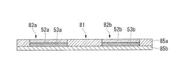
図6Cは、遮蔽板の第3の変形例を示し、帯状鋼板10の搬送方向に沿って遮蔽板の厚み方向に切ったときの遮蔽板の断面図である。図6Cは、図4Bに対応している。
図6Cにおいて、遮蔽板81は、銅製であり、帯状鋼板10の搬送方向に間隔を有して配置され、それぞれ大きさと形状が同一の凹部82a、82b(82)を有している。また、凹部82a、82bの板面方向における形状(開口形状)は、それぞれの角部が丸みを帯びた菱形である。このように、図6Cに示す遮蔽板81と、図4A〜4Cに示した遮蔽板31とは、材質、形状、及び大きさが同じである。ただし、図6Cに示す遮蔽板81は、上板84aと下板84bとを重ね合わせてそれらを固定することにより形成される。
以上のように、遮蔽板は、一体で形成しても、複数の部材を組み合せて形成してもよい。
これらの他、本実施形態では、遮蔽板が銅製であるが、遮蔽板は銅製の板に限定されない。すなわち、遮蔽板が、導体、好ましくは比透磁率が1の導体であれば、どのような材料で遮蔽板を形成してもよい。例えば、アルミニウムで遮蔽板を形成することができる。FIG. 6C shows a third modification of the shielding plate, and is a cross-sectional view of the shielding plate when cut in the thickness direction of the shielding plate along the conveying direction of the
In FIG. 6C, the shielding
As described above, the shielding plate may be formed integrally or may be formed by combining a plurality of members.
In addition to these, in the present embodiment, the shielding plate is made of copper, but the shielding plate is not limited to a copper plate. That is, as long as the shielding plate is a conductor, preferably a conductor having a relative magnetic permeability of 1, the shielding plate may be formed of any material. For example, the shielding plate can be formed of aluminum.
なお、本実施形態では、非導電性軟磁性板(非導電性軟磁性材)の近傍に生じている遮蔽板中の渦電流の大きさを大きくすることによって、主磁束により帯状鋼板(導体板)10の側端部に流れている渦電流の大きさを低減している。さらに、コア(または、加熱コイル)と非導電性軟磁性板との間に、導電性の遮蔽板が介在するため、主磁束が直接非導電性軟磁性板を通過することを避けることができる。そのため、誘導加熱装置が、加熱コイルと;コアと;このコアと、帯状鋼板の搬送方向に垂直な方向における側端部との間に配置される導電性の遮蔽板と;コアと非導電性軟磁性板との間に遮蔽板が介在するように遮蔽板に取り付けられる非導電性軟磁性板とを備えていればよい。 In this embodiment, a strip steel plate (conductor plate) is generated by the main magnetic flux by increasing the magnitude of eddy current in the shielding plate generated in the vicinity of the nonconductive soft magnetic plate (nonconductive soft magnetic material). ) The magnitude of the eddy current flowing in the side end portion of 10 is reduced. Furthermore, since the conductive shielding plate is interposed between the core (or the heating coil) and the non-conductive soft magnetic plate, it is possible to avoid the main magnetic flux passing directly through the non-conductive soft magnetic plate. . Therefore, the induction heating device includes: a heating coil; a core; a conductive shielding plate disposed between the core and a side end portion in a direction perpendicular to the conveying direction of the strip steel plate; What is necessary is just to provide the nonelectroconductive soft-magnetic board attached to a shielding board so that a shielding board may interpose with a soft-magnetic board.
そのため、例えば、図7A〜7C及び図8A〜8Cに示すような非導電性軟磁性板が取り付けられた遮蔽板を使用することができる。なお、図7A〜7Cは、本実施形態の第4〜6の変形例における遮蔽板の構成の一例を示す縦断面図である。また、図8A〜8Cは、本実施形態の第7〜9の変形例における遮蔽板の構成の一例を示す斜視図である。
図7Aに示す本実施形態の第4の変形例では、平らな遮蔽板101の上に非導電性軟磁性板102a、102b(102)を配置し、非導電性軟磁性板102を帯状鋼板の側端部に対向させている。このように、遮蔽板に凹部を形成せず、遮蔽板上に凸部が形成されるように遮蔽板に非導電性軟磁性板を取り付けてもよい。この場合には、遮蔽板と非導電性軟磁性板との接触面の周縁部における遮蔽板中の渦電流を増加させることができる。しかしながら、遮蔽板に凹部を形成し、この凹部に非導電性軟磁性板を配置することによって、凹部の縁に渦電流を束縛し、この凹部の縁と非導電性軟磁性板との距離を縮めることができるため、凹部の縁により大きな渦電流を確保することができる。そのため、図7B(第5の実施形態)に示すように、遮蔽板111に凹部114a、114b(114)を形成し、遮蔽板111上に凸部が形成されるように遮蔽板111の凹部114に非導電性軟磁性板112a、112b(112)を取り付けてもよい。また、図7C(第6の実施形態)に示すように、遮蔽板121の凹部124a、124b(124)に上面の形状と下面の形状とが異なる非導電性軟磁性板122a、122b(122)を取り付けてもよい。Therefore, for example, a shielding plate to which a non-conductive soft magnetic plate as shown in FIGS. 7A to 7C and FIGS. 8A to 8C is attached can be used. 7A to 7C are longitudinal sectional views showing an example of the configuration of the shielding plate in the fourth to sixth modifications of the present embodiment. 8A to 8C are perspective views showing an example of the configuration of the shielding plate in the seventh to ninth modifications of the present embodiment.
In the fourth modification of the present embodiment shown in FIG. 7A, non-conductive soft
また、図8Aに示す第7の変形例では、凸部(2つの菱形部)205a、205b(205)を有する遮蔽板201の上に非導電性軟磁性板202を取り付けている。この場合には、凸部205の縁に流れる渦電流を大きくすることができる。また、遮蔽板の形状(外周形状)は、特に限定されない。図8Bに示す第8の変形例では、遮蔽板211に凹部(2つの菱形部)214a、214b(214)が形成され、遮蔽板211は、この凹部214の外周形状(開口形状)に沿った枠部216a、216bを有している。さらに、凹部214には、非導電性軟磁性板212a、212b(212)が収められている。この場合には、凹部214の縁に流れる渦電流を大きくすることができる。また、図8Cに示す第9の変形例では、遮蔽板221に凸部(2つの菱形部)225a、225b(225)が形成され、遮蔽板221は、この凸部225の外周形状(基端形状)に類似した(沿った)外周形状を有している。さらに、遮蔽板221上には、凸部225の縁部を取り囲むように、非導電性軟磁性板222が配置されている。この場合には、凸部225の縁に流れる渦電流を大きくすることができる。
In the seventh modification shown in FIG. 8A, a non-conductive soft
なお、図7A〜7C及び図8A〜8Cに示す各変形例の非導電性軟磁性板の上に、耐熱板を取り付けてもよい。また、板面方向における遮蔽板の凹部または凸部の形状及び数は、特に限定されない。さらに、非導電性軟磁性板の形状及び数も、特に限定されない。 In addition, you may attach a heat-resistant board on the nonelectroconductive soft magnetic board of each modification shown to FIG. 7A-7C and FIG. 8A-8C. Moreover, the shape and number of the recessed part or convex part of the shielding board in a board surface direction are not specifically limited. Furthermore, the shape and number of non-conductive soft magnetic plates are not particularly limited.
非導電性軟磁性材の近傍を流れる遮蔽板中の渦電流の大きさをできる限り大きくすることが望ましい。以下に、この渦電流をより大きくする構成について、説明する。
図4Eは、図4BのC−C’方向から見た断面図である。図4Eに示すように、この切断面には、非導電性軟磁性板52a、52b(52)が含まれており、遮蔽板31と非導電性軟磁性板52との間の境界部(境界線)が閉曲線(2つの閉曲線)を描いている。すなわち、この切断面には、遮蔽板が非導電性軟磁性板を取り囲む場合と、非導電性軟磁性板が遮蔽板を取り囲む場合とが含まれる。このように、遮蔽板が、非導電性軟磁性材を含む厚み方向に垂直な切断面(コイル面に平行な切断面)を有していると、非導電性軟磁性材と、この非導電性軟磁性板によって強められる遮蔽板中の渦電流との距離を短くすることができる。さらに、上述の境界部が閉曲線を描く(リング状である)ことにより、強化される渦電流の領域を増やすことができ、非導電性軟磁性板の特性を十分に活かすことができる。なお、非導電性軟磁性材の近傍を流れる遮蔽板中の渦電流の大きさをできる限り大きくするために、遮蔽板と非導電性軟磁性材とが接触していることが好ましい。しかしながら、非導電性軟磁性材を遮蔽板に容易に取り付けることができるように、遮蔽板と非導電性軟磁性材との間に隙間(境界部としての隙間)が存在してもよい。It is desirable to increase the magnitude of the eddy current in the shielding plate flowing in the vicinity of the non-conductive soft magnetic material as much as possible. Below, the structure which makes this eddy current larger is demonstrated.
4E is a cross-sectional view seen from the CC ′ direction in FIG. 4B. As shown in FIG. 4E, the cut surface includes non-conductive soft
また、誘導加熱装置を高温下で使用する場合や帯状鋼板を急速加熱する場合には、渦電流により遮蔽板の温度が高くなることがある。この場合には、水冷パイプ等の冷却器を用いて遮蔽板及び非導電性軟磁性材を冷却することが好ましい。この冷却方法は、特に限定されない。例えば、遮蔽板中に水冷ラインを一体的に形成して遮蔽板を冷却したり、送風器により遮蔽板に送風して遮蔽板を冷却したりしてもよい。 Moreover, when using an induction heating apparatus under high temperature, or when heating a strip steel plate rapidly, the temperature of a shielding board may become high with an eddy current. In this case, it is preferable to cool the shielding plate and the non-conductive soft magnetic material using a cooler such as a water-cooled pipe. This cooling method is not particularly limited. For example, a water cooling line may be integrally formed in the shielding plate to cool the shielding plate, or air may be blown to the shielding plate by a blower to cool the shielding plate.
<非導電性軟磁性板、耐熱板>
非導電性軟磁性板を構成する材料は、非導電性の軟磁性体であれば、軟磁性フェライトに限定されない。また、非導電性軟磁性材は、板ではなく、粉体や粒体を押し固めた材料や、複数のブロックを組み合わせた材料であってもよい。また、非導電性軟磁性板の形状は、特に限定されない。遮蔽板の内側の渦電流が流れる部分(例えば、凹部の縁)に合わせて非導電性軟磁性板を配置することができれば、この渦電流を強化する磁界を得ることができるため、例えば、非導電性軟磁性板が、中空部を有してもよい。しかしながら、非導電性軟磁性板の磁性を十分に利用するためには、非導電性軟磁性板は、中実であることが好ましい。
耐熱板についても、必ずしも板である必要はなく、耐熱材を用いていればどのような材料であってもよい。
また、凹部に収められる非導電性軟磁性板及び耐熱板を、凹部内に固定する方法は、接着剤を用いる方法に限定されない。例えば、遮蔽板と非導電性軟磁性板及び耐熱板との絶縁を確保した上で螺子を用いてこれらを凹部に固定することができる。<Non-conductive soft magnetic plate, heat-resistant plate>
The material constituting the nonconductive soft magnetic plate is not limited to soft magnetic ferrite as long as it is a nonconductive soft magnetic material. Further, the non-conductive soft magnetic material may be a material obtained by pressing and solidifying powder or particles, or a material combining a plurality of blocks, instead of a plate. Further, the shape of the non-conductive soft magnetic plate is not particularly limited. If a non-conductive soft magnetic plate can be arranged in accordance with the part where the eddy current flows inside the shielding plate (for example, the edge of the recess), a magnetic field that enhances the eddy current can be obtained. The conductive soft magnetic plate may have a hollow portion. However, in order to fully utilize the magnetism of the nonconductive soft magnetic plate, the nonconductive soft magnetic plate is preferably solid.
The heat-resistant plate is not necessarily a plate, and any material may be used as long as a heat-resistant material is used.
Further, the method of fixing the non-conductive soft magnetic plate and the heat-resistant plate stored in the recess in the recess is not limited to the method using an adhesive. For example, after securing insulation between the shielding plate, the non-conductive soft magnetic plate, and the heat-resistant plate, these can be fixed to the recess using a screw.
<その他>
本実施形態では、誘導加熱装置20の配置箇所は、図1に示した位置に限定されない。すなわち、導体板をトランスバース方式で誘導加熱することが可能であれば、誘導加熱装置20をどのように配置してもよい。例えば、第2の容器12内に誘導加熱装置20を配置してもよい。また、連続焼鈍ライン以外に誘導加熱装置20を適用してもよい。
また、本実施形態では、加熱コイル幅と加熱コイル間のギャップとが同じである場合を例に挙げて説明したが、加熱コイル幅及びこのギャップの大きさは、特に限定されるものではない。ただし、加熱コイル幅がギャップ以上である(又は加熱コイル幅がギャップよりも大きい)のが好ましい。この場合には、誘導加熱装置20から発生する主磁場が漏れ磁場よりも多くなり、誘導加熱装置20の加熱効率を良好にできる。尚、加熱コイル幅の上限値は、誘導加熱装置20を配置するスペースや、誘導加熱装置20に要求される重量やコスト等の条件によって適宜決定することができる。さらに、加熱コイル及びコアの配置数は、特に限定されない。例えば、加熱コイル及びコアは、帯状鋼板の加熱制御を柔軟に行なうために、帯状鋼板の搬送方向に複数配置することができる。
さらに、遮蔽板の配置数も、特に制限されない。例えば、加熱コイル及びコアの配置数に応じて、帯状鋼板の搬送方向に複数配置しても良い。1つの凹部を有する遮蔽板を複数配置して、複数の凹部を有する遮蔽板ユニットを形成しても良い。
また、本実施形態では、上側誘導器21と下側誘導器22とを設ける場合を例に挙げて示したが、上側誘導器21と下側誘導器22との何れか一方のみを設けてもよい。<Others>
In this embodiment, the arrangement | positioning location of the
In the present embodiment, the case where the heating coil width and the gap between the heating coils are the same has been described as an example, but the heating coil width and the size of the gap are not particularly limited. However, the heating coil width is preferably equal to or greater than the gap (or the heating coil width is larger than the gap). In this case, the main magnetic field generated from the
Further, the number of shielding plates is not particularly limited. For example, according to the number of arrangement | positioning of a heating coil and a core, you may arrange several in the conveyance direction of a strip steel plate. A plurality of shielding plates having one recess may be arranged to form a shielding plate unit having a plurality of recesses.
Moreover, in this embodiment, although the case where the
尚、以上説明した本発明の実施形態は、何れも本発明を実施するにあたっての具体化の例を示したものに過ぎず、これらによって本発明の技術的範囲が限定的に解釈されてはならない。すなわち、本発明は、その技術思想、またはその主要な特徴から逸脱することなく、様々な形で実施することができる。 It should be noted that the embodiments of the present invention described above are merely examples of implementation in carrying out the present invention, and the technical scope of the present invention should not be construed as being limited thereto. . That is, the present invention can be implemented in various forms without departing from the technical idea or the main features thereof.
加熱対象の導体板の幅方向における温度分布が不均一になることを緩和し、加熱対象の導体板が蛇行することにより導体板の幅方向における温度分布が変動することを緩和することができるトランスバース方式の誘導加熱装置を提供する。 Transformer that can mitigate uneven temperature distribution in the width direction of the conductor plate to be heated, and mitigate fluctuations in temperature distribution in the width direction of the conductor plate due to the meandering of the conductor plate to be heated. A berth type induction heating apparatus is provided.
10 帯状鋼板(導体板)
18 交流電源装置
20 誘導加熱装置
21 上側誘導器
22 下側誘導器
23、27 コア
24 上側加熱コイル(加熱コイル)
28 下側加熱コイル(加熱コイル)
31、61、71、81、101、111、121、201、211、221 遮蔽板
51、62、72、82、114、124、214 凹部
205、225 凸部
52、102、112、122、202、212、222 非導電性軟磁性板(非導電性軟磁性材)
53、63、73 耐熱板(耐熱材)
10 Strip steel plate (conductor plate)
18 AC
28 Lower heating coil (heating coil)
31, 61, 71, 81, 101, 111, 121, 201, 211, 221
53, 63, 73 Heat-resistant plate (heat-resistant material)
Claims (6)
前記導体板の板面に対してコイル面が対向するように配置された加熱コイルと;
この加熱コイルが巻き回されたコアと;
このコアと、前記導体板の搬送方向に垂直な方向における側端部との間に配置され、導体から形成された遮蔽板と;
この遮蔽板に取り付けられる非導電性軟磁性材と;
を備え、
前記遮蔽板の前記導体板と対向する面には、前記導体板の搬送方向に垂直な方向における前記側端部と対向する凹部が形成されており;
この凹部に、前記非導電性軟磁性材が収められ;
前記コアと前記非導電性軟磁性材との間に、前記遮蔽板が介在している
ことを特徴とするトランスバース方式の誘導加熱装置。An induction heating device of a transverse system that inductively heats the conductor plate by crossing an alternating magnetic field with the plate surface of the conductor plate conveyed in one direction,
A heating coil arranged such that the coil surface faces the plate surface of the conductor plate;
A core around which the heating coil is wound;
A shielding plate disposed between the core and a side end portion in a direction perpendicular to the conveying direction of the conductor plate, and formed from a conductor;
A non-conductive soft magnetic material attached to the shielding plate;
With
On the surface of the shielding plate facing the conductor plate, a recess facing the side end portion in a direction perpendicular to the conveying direction of the conductor plate is formed;
The non-conductive soft magnetic material is accommodated in the recess;
A transverse induction heating apparatus , wherein the shielding plate is interposed between the core and the non-conductive soft magnetic material.
前記耐熱板が前記非導電性軟磁性体よりも前記導体板の近くに配置されている;
ことを特徴とする請求項1に記載のトランスバース方式の誘導加熱装置。A heat-resistant plate attached to the non-conductive soft magnetic material;
The heat-resistant plate is disposed closer to the conductor plate than the non-conductive soft magnetic material;
The transverse type induction heating apparatus according to claim 1.
これら第一の部分及び第二の部分が、前記導体板の搬送方向で相互に対向している;
ことを特徴とする請求項1乃至請求項3の何れか一項に記載のトランスバース方式の誘導加熱装置。The recess has a first portion that tapers from the upstream side to the downstream side in the transport direction of the conductor plate, and a second portion that tapers from the downstream side to the upstream side in the transport direction of the conductor plate. Part and include;
The first part and the second part are opposed to each other in the conveying direction of the conductor plate;
The transverse type induction heating apparatus according to any one of claims 1 to 3, wherein the induction heating apparatus is a transverse type.
前記第二の部分が、前記上流側に向けて丸みを帯びている;
ことを特徴とする請求項5に記載のトランスバース方式の誘導加熱装置。The first portion is rounded toward the downstream side;
The second portion is rounded toward the upstream side;
The transverse type induction heating apparatus according to claim 5 , wherein:
Priority Applications (1)
| Application Number | Priority Date | Filing Date | Title |
|---|---|---|---|
| JP2011527919A JP4938155B2 (en) | 2010-02-19 | 2011-02-18 | Transverse induction heating device |
Applications Claiming Priority (4)
| Application Number | Priority Date | Filing Date | Title |
|---|---|---|---|
| JP2010035198 | 2010-02-19 | ||
| JP2010035198 | 2010-02-19 | ||
| JP2011527919A JP4938155B2 (en) | 2010-02-19 | 2011-02-18 | Transverse induction heating device |
| PCT/JP2011/053526 WO2011102471A1 (en) | 2010-02-19 | 2011-02-18 | Transverse flux induction heating device |
Publications (2)
| Publication Number | Publication Date |
|---|---|
| JP4938155B2 true JP4938155B2 (en) | 2012-05-23 |
| JPWO2011102471A1 JPWO2011102471A1 (en) | 2013-06-17 |
Family
ID=44483056
Family Applications (1)
| Application Number | Title | Priority Date | Filing Date |
|---|---|---|---|
| JP2011527919A Active JP4938155B2 (en) | 2010-02-19 | 2011-02-18 | Transverse induction heating device |
Country Status (12)
| Country | Link |
|---|---|
| US (2) | US10292210B2 (en) |
| EP (1) | EP2538749B1 (en) |
| JP (1) | JP4938155B2 (en) |
| KR (1) | KR101358555B1 (en) |
| CN (1) | CN102884862B (en) |
| BR (1) | BR112012020606B1 (en) |
| CA (1) | CA2789978C (en) |
| HK (1) | HK1179097A1 (en) |
| MX (1) | MX2012009520A (en) |
| PL (1) | PL2538749T3 (en) |
| RU (1) | RU2518187C2 (en) |
| WO (1) | WO2011102471A1 (en) |
Families Citing this family (12)
| Publication number | Priority date | Publication date | Assignee | Title |
|---|---|---|---|---|
| ES2434856R1 (en) * | 2011-10-21 | 2013-12-27 | Bsh Electrodomesticos Espana | Induction heating device and domestic induction heating device with said device |
| JP5751453B2 (en) | 2012-10-04 | 2015-07-22 | 株式会社デンソー | Induction heating device |
| US10568166B2 (en) * | 2014-09-05 | 2020-02-18 | Nippon Steel Corporation | Induction heating device for metal strip |
| EP3091818B1 (en) * | 2015-05-05 | 2018-07-11 | Electrolux Appliances Aktiebolag | Induction coil for an induction hearing appliance |
| US10059054B2 (en) | 2015-06-29 | 2018-08-28 | The Boeing Company | Welding thermoplastic structures |
| JP6195043B1 (en) * | 2016-03-24 | 2017-09-13 | 新日鐵住金株式会社 | 3D hot bending and quenching apparatus and 3D hot bending and quenching method of steel pipe |
| EP3439430B1 (en) * | 2016-03-30 | 2023-08-23 | Nippon Steel Corporation | Induction heating device and induction heating method |
| CA3037752C (en) | 2016-09-27 | 2022-11-15 | Novelis Inc. | Magnetic levitation heating of metal with controlled surface quality |
| CA3211514A1 (en) | 2016-09-27 | 2018-04-05 | Novelis Inc. | Rotating magnet heat induction |
| WO2018106053A2 (en) * | 2016-12-09 | 2018-06-14 | 주식회사 아모센스 | Heating module for induction range and induction range comprising same |
| US20180164036A1 (en) * | 2016-12-12 | 2018-06-14 | Fluxtrol Inc. | Cold crucible insert |
| WO2020228964A1 (en) * | 2019-05-16 | 2020-11-19 | Vestel Elektronik Sanayi Ve Ticaret A.S. | Induction cooker, method and computer program product for adjusting air gap for induction coil |
Citations (2)
| Publication number | Priority date | Publication date | Assignee | Title |
|---|---|---|---|---|
| JPS6235490A (en) * | 1985-08-09 | 1987-02-16 | 住友重機械工業株式会社 | Electromagnetic induction heater |
| JP2003133037A (en) * | 2001-10-26 | 2003-05-09 | Toyo Seikan Kaisha Ltd | Induction heating method and device for metal band plate |
Family Cites Families (82)
| Publication number | Priority date | Publication date | Assignee | Title |
|---|---|---|---|---|
| US2448008A (en) | 1943-12-07 | 1948-08-31 | Westinghouse Electric Corp | Controlled induction heating |
| US2448009A (en) | 1944-02-05 | 1948-08-31 | Westinghouse Electric Corp | Inductive heating of longitudinally moving metal strip |
| US2448062A (en) | 1944-09-09 | 1948-08-31 | Westinghouse Electric Corp | Transverse flux induction heating apparatus |
| US2448012A (en) | 1944-09-09 | 1948-08-31 | Westinghouse Electric Corp | Induced heating of continuously moving metal strip with pulsating magnetic flux |
| US2448011A (en) | 1944-09-09 | 1948-08-31 | Westinghouse Electric Corp | Method and apparatus for induction heating of metal strips |
| US2452197A (en) | 1945-03-22 | 1948-10-26 | Ajax Electrothermic Corp | Induction furnace for variable heat patterns |
| US2556223A (en) * | 1947-05-28 | 1951-06-12 | Westinghouse Electric Corp | Induction heating of flat metal by transverse flux |
| US2761939A (en) | 1948-11-30 | 1956-09-04 | Metallurg Tech Et Commerciale | Apparatus for welding by means of electromagnetic induction heating |
| US2722589A (en) | 1950-11-30 | 1955-11-01 | Ohio Crankshaft Co | Method and apparatus for uniformly heating intermittently moving metallic material |
| US2773161A (en) | 1954-05-25 | 1956-12-04 | Westinghouse Electric Corp | Combination control system for continuous heat treatment |
| NL243545A (en) * | 1958-09-19 | 1900-01-01 | ||
| CH416879A (en) * | 1963-04-01 | 1966-07-15 | Baermann Max | Furnace for heating metallic parts |
| US3444346A (en) * | 1966-12-19 | 1969-05-13 | Texas Instruments Inc | Inductive heating of strip material |
| US3508024A (en) * | 1968-06-17 | 1970-04-21 | Gen Electric | Dual inductance induction heater |
| US3705967A (en) * | 1971-02-08 | 1972-12-12 | United States Steel Corp | Induction heating method |
| US3720803A (en) * | 1972-06-02 | 1973-03-13 | Park Ohio Industries Inc | Method and apparatus for inductively heat treating elongated workpieces |
| US4321444A (en) | 1975-03-04 | 1982-03-23 | Davies Evan J | Induction heating apparatus |
| JPS531614A (en) | 1976-06-26 | 1978-01-09 | Toyo Alum Kk | Induction heating equipment |
| US4357512A (en) | 1980-07-23 | 1982-11-02 | Sumitomo Kinzoku Kogyo Kabushiki Kaisha | Apparatus for continuous manufacture of butt-welded pipe |
| FR2521797B1 (en) | 1982-02-18 | 1985-12-06 | Cem Comp Electro Mec | METHOD AND DEVICES FOR MINIMIZING THE INDUCED POWER IN A CONDUCTIVE FLAT PRODUCT MAINTAINED ELECTROMAGNETICALLY NON-CONTACT |
| FR2523395A1 (en) | 1982-03-12 | 1983-09-16 | Cem Comp Electro Mec | METHOD AND DEVICE FOR ADJUSTING THE AVERAGE INDUCED HEATING POWER IN A CONDUCTIVE FLAT CONTAINING ELECTROMAGNETICALLY IN CONTACTLESS POSITION |
| US4585916A (en) | 1982-06-02 | 1986-04-29 | Davy Mckee (Poole) Limited | Transverse flux induction heating of metal strip |
| FR2566986B1 (en) | 1984-06-28 | 1986-09-19 | Electricite De France | ELECTROMAGNETIC INDUCTION DEVICE FOR HEATING METAL ELEMENTS |
| FR2583249B1 (en) | 1985-06-07 | 1989-04-28 | Siderurgie Fse Inst Rech | DEVICE FOR INDUCTIVELY HEATING THE RIVES OF A METALLURGICAL PRODUCT AND VARIABLE GAP INDUCTOR |
| US4649249A (en) * | 1985-09-13 | 1987-03-10 | Rockwell International Corporation | Induction heating platen for hot metal working |
| JPS6298588A (en) | 1985-10-25 | 1987-05-08 | 日本軽金属株式会社 | Electromagnetic induction heater |
| US4778971A (en) | 1986-05-23 | 1988-10-18 | Kabushiki Kaisha Meidensha | Induction heating apparatus |
| US4751360A (en) | 1987-06-26 | 1988-06-14 | Ross Nicholas V | Apparatus for the continuous induction heating of metallic strip |
| GB8721663D0 (en) | 1987-09-15 | 1987-10-21 | Electricity Council | Induction heating apparatus |
| JP2816680B2 (en) | 1987-11-30 | 1998-10-27 | 高周波熱錬 株式会社 | Strip heating device |
| GB8902090D0 (en) | 1989-01-31 | 1989-03-22 | Metal Box Plc | Electro-magnetic induction heating apparatus |
| SE464019B (en) | 1989-03-13 | 1991-02-25 | Tetra Pak Holdings & Finance | DEVICE FOR CONTINUOUS INDUCTION WELDING OF PACKAGING MATERIAL |
| IT1229749B (en) | 1989-05-17 | 1991-09-10 | Giovanni Arvedi | HEATING INDUCTION OVEN AND TEMPERATURE HOMOGENIZATION FOR THE LAMINATION OF THIN STEEL BELTS. |
| EP0438130B1 (en) | 1990-01-17 | 1995-10-18 | Sumitomo Heavy Industries, Ltd | An electromagnetic induction heater |
| FR2661849B1 (en) | 1990-05-10 | 1995-03-17 | Siderurgie Fse Inst Rech | METHOD AND DEVICES FOR INDUCTION HEATING OF A METALLURGICAL PRODUCT IN AN ELONGATE SHAPE. |
| IT1253095B (en) | 1991-12-18 | 1995-07-10 | Giovanni Arvedi | INDUCTION OVEN PERFECTED FOR HEATING OR TEMPERATURE RESTORATION IN FLAT STEEL PRODUCTS |
| EP0591542B1 (en) | 1992-03-18 | 2003-01-02 | Sumitomo Special Metals Company Limited | Magnetic field generator for mri |
| JPH05266975A (en) | 1992-03-19 | 1993-10-15 | Sumitomo Heavy Ind Ltd | Induction heater for dry process line |
| FR2693071B1 (en) * | 1992-06-24 | 2000-03-31 | Celes | DEVICE FOR HOMOGENEOUS INDUCTIVE HEATING OF FLAT METAL PRODUCTS IN A RUNWAY. |
| JP3582842B2 (en) | 1993-02-02 | 2004-10-27 | ジオルジオ・ボルミオリ | Quick fittings |
| US5403994A (en) | 1994-02-14 | 1995-04-04 | Ajax Magnethermic Corporation | Selectively adjustable transverse flux heating apparatus |
| US5495094A (en) | 1994-04-08 | 1996-02-27 | Inductotherm Corp. | Continuous strip material induction heating coil |
| FR2726962B1 (en) | 1994-11-15 | 1996-12-13 | Europ Equip Menager | REDUCED PARASITE RADIATION INDUCTION COOKING APPARATUS |
| US5822669A (en) | 1995-08-29 | 1998-10-13 | Minolta Co., Ltd. | Induction heat fusing device |
| US5739506A (en) * | 1996-08-20 | 1998-04-14 | Ajax Magnethermic Corporation | Coil position adjustment system in induction heating assembly for metal strip |
| US5770838A (en) | 1996-09-11 | 1998-06-23 | Drever Company | Induction heaters to improve transitions in continuous heating system, and method |
| US5827056A (en) | 1997-01-09 | 1998-10-27 | Drever Company | Device and method for improving strip tracking in a continuous heating furnace |
| US5837976A (en) | 1997-09-11 | 1998-11-17 | Inductotherm Corp. | Strip heating coil apparatus with series power supplies |
| US6180928B1 (en) | 1998-04-07 | 2001-01-30 | The Boeing Company | Rare earth metal switched magnetic devices |
| US6067015A (en) * | 1998-07-09 | 2000-05-23 | Senormatic Electronics Corporation | Magnetomechanical EAS marker with reduced-size bias magnet |
| JP2001006861A (en) | 1999-06-22 | 2001-01-12 | Sumitomo Heavy Ind Ltd | Electromagnetic induction heating device |
| JP2001006864A (en) | 1999-06-25 | 2001-01-12 | Nkk Corp | Induction heating device |
| US6271507B2 (en) | 1999-10-08 | 2001-08-07 | Molex Incorporated | Apparatus and method for bonding conductors |
| FR2808163B1 (en) | 2000-04-19 | 2002-11-08 | Celes | TRANSVERSE FLOW INDUCTION HEATING DEVICE WITH MAGNETIC CIRCUIT OF VARIABLE WIDTH |
| US6576878B2 (en) * | 2001-01-03 | 2003-06-10 | Inductotherm Corp. | Transverse flux induction heating apparatus |
| US6570141B2 (en) | 2001-03-26 | 2003-05-27 | Nicholas V. Ross | Transverse flux induction heating of conductive strip |
| ITBO20010224A1 (en) | 2001-04-17 | 2002-10-17 | Gd Spa | METHOD OF DETECTION OF THE TEMPERATURE OF A BELT AT LEAST PARALLEL METALLIC IN A PACKAGING MACHINE AND SEALING UNIT |
| FR2838282B1 (en) | 2002-04-04 | 2004-06-11 | Celes | IMPROVEMENTS IN OR RELATING TO HEATING INDUCERS, ESPECIALLY METAL STRIPS |
| US20030222079A1 (en) * | 2002-05-30 | 2003-12-04 | Lawton Robert J. | System for inductively heating a belt |
| FR2843230B1 (en) | 2002-08-02 | 2005-04-29 | Commissariat Energie Atomique | MAGNETIC ACTUATOR WITH LEVITATION |
| US6872925B2 (en) | 2002-08-05 | 2005-03-29 | Matsushita Electric Industrial Co., Ltd. | Image heating device using induction heating and image forming apparatus |
| US6963056B1 (en) | 2003-05-09 | 2005-11-08 | Inductotherm Corp. | Induction heating of a workpiece |
| BRPI0411858A2 (en) | 2003-06-26 | 2008-12-16 | Inductotherm Corp | electromagnetic shielding, and method for shielding a magnetic field |
| JP4295141B2 (en) | 2004-03-12 | 2009-07-15 | 株式会社吉野工作所 | Work heating apparatus and work heating method |
| US9888529B2 (en) | 2005-02-18 | 2018-02-06 | Nippon Steel & Sumitomo Metal Corporation | Induction heating device for a metal plate |
| CN101120616B (en) | 2005-02-18 | 2011-06-08 | 新日本制铁株式会社 | Induction heating device for metal plate |
| US20070012663A1 (en) | 2005-07-13 | 2007-01-18 | Akihiro Hosokawa | Magnetron sputtering system for large-area substrates having removable anodes |
| US7297907B2 (en) | 2005-12-08 | 2007-11-20 | Uri Rapoport | Means and method of maintaining a constant temperature in the magnetic assembly of a magnetic resonance device |
| CN101401485A (en) | 2006-01-09 | 2009-04-01 | 应达公司 | Electromagnetically shielded induction heating apparatus |
| CA2641846A1 (en) | 2006-02-22 | 2007-09-07 | Inductotherm Corp. | Transverse flux electric inductors |
| EP2008499A2 (en) | 2006-03-29 | 2008-12-31 | Inductotherm Corp. | Transverse flux induction heating apparatus and compensators |
| US7534980B2 (en) * | 2006-03-30 | 2009-05-19 | Ut-Battelle, Llc | High magnetic field ohmically decoupled non-contact technology |
| JP5114671B2 (en) * | 2007-04-16 | 2013-01-09 | 新日鐵住金株式会社 | Induction heating apparatus and induction heating method for metal plate |
| US20090057301A1 (en) * | 2007-08-28 | 2009-03-05 | Jean Lovens | Electric induction heating apparatus with fluid medium flow through |
| JP4626683B2 (en) | 2007-08-29 | 2011-02-09 | トヨタ自動車株式会社 | Steel material having nonmagnetic portion, method for manufacturing the same, and rotating electric machine core |
| WO2009129239A2 (en) * | 2008-04-14 | 2009-10-22 | Inductotherm Corp. | Variable width transverse flux electric induction coils |
| US20110033077A1 (en) | 2008-04-15 | 2011-02-10 | Nxp B.V. | Magnet system and method of manufacturing the same |
| JP4959651B2 (en) * | 2008-08-11 | 2012-06-27 | 新日本製鐵株式会社 | Transverse induction heating system |
| US8803046B2 (en) | 2009-08-11 | 2014-08-12 | Radyne Corporation | Inductor assembly for transverse flux electric induction heat treatment of electrically conductive thin strip material with low electrical resistivity |
| JP4525844B2 (en) | 2009-10-05 | 2010-08-18 | 三菱電機株式会社 | Recording / playback method |
| EP2515609B1 (en) | 2009-12-14 | 2018-02-07 | Nippon Steel & Sumitomo Metal Corporation | Control device for induction heating device and method for controlling induction heating system and induction heating device |
| CN102783248B (en) | 2010-02-19 | 2014-10-15 | 新日铁住金株式会社 | Transverse flux induction heating device |
-
2011
- 2011-02-18 JP JP2011527919A patent/JP4938155B2/en active Active
- 2011-02-18 US US13/577,967 patent/US10292210B2/en active Active
- 2011-02-18 MX MX2012009520A patent/MX2012009520A/en active IP Right Grant
- 2011-02-18 CN CN201180009731.7A patent/CN102884862B/en active Active
- 2011-02-18 EP EP11744757.3A patent/EP2538749B1/en active Active
- 2011-02-18 KR KR1020127022442A patent/KR101358555B1/en active IP Right Grant
- 2011-02-18 CA CA2789978A patent/CA2789978C/en active Active
- 2011-02-18 BR BR112012020606-0A patent/BR112012020606B1/en active IP Right Grant
- 2011-02-18 RU RU2012137107/07A patent/RU2518187C2/en active
- 2011-02-18 WO PCT/JP2011/053526 patent/WO2011102471A1/en active Application Filing
- 2011-02-18 PL PL11744757T patent/PL2538749T3/en unknown
-
2013
- 2013-05-17 HK HK13105865.6A patent/HK1179097A1/en unknown
-
2018
- 2018-08-22 US US16/108,604 patent/US10327287B2/en active Active
Patent Citations (2)
| Publication number | Priority date | Publication date | Assignee | Title |
|---|---|---|---|---|
| JPS6235490A (en) * | 1985-08-09 | 1987-02-16 | 住友重機械工業株式会社 | Electromagnetic induction heater |
| JP2003133037A (en) * | 2001-10-26 | 2003-05-09 | Toyo Seikan Kaisha Ltd | Induction heating method and device for metal band plate |
Also Published As
| Publication number | Publication date |
|---|---|
| BR112012020606B1 (en) | 2021-02-23 |
| MX2012009520A (en) | 2012-08-31 |
| CN102884862B (en) | 2014-11-19 |
| CN102884862A (en) | 2013-01-16 |
| EP2538749A4 (en) | 2015-07-29 |
| EP2538749B1 (en) | 2018-04-04 |
| EP2538749A1 (en) | 2012-12-26 |
| WO2011102471A1 (en) | 2011-08-25 |
| US20180359817A1 (en) | 2018-12-13 |
| CA2789978C (en) | 2015-11-24 |
| PL2538749T3 (en) | 2018-09-28 |
| CA2789978A1 (en) | 2011-08-25 |
| KR20120116988A (en) | 2012-10-23 |
| BR112012020606A2 (en) | 2016-07-19 |
| HK1179097A1 (en) | 2013-09-19 |
| RU2518187C2 (en) | 2014-06-10 |
| US10292210B2 (en) | 2019-05-14 |
| JPWO2011102471A1 (en) | 2013-06-17 |
| RU2012137107A (en) | 2014-03-27 |
| KR101358555B1 (en) | 2014-02-05 |
| US10327287B2 (en) | 2019-06-18 |
| US20120305548A1 (en) | 2012-12-06 |
Similar Documents
| Publication | Publication Date | Title |
|---|---|---|
| JP4938155B2 (en) | Transverse induction heating device | |
| JP5114671B2 (en) | Induction heating apparatus and induction heating method for metal plate | |
| US10085306B2 (en) | Transverse flux induction heating device | |
| KR101102609B1 (en) | Induction heating device | |
| JP6323564B2 (en) | Induction heating device for metal strip | |
| KR102196842B1 (en) | Induction heating device and induction heating method | |
| JP5042909B2 (en) | Induction heating apparatus and induction heating method for metal plate | |
| JP4959651B2 (en) | Transverse induction heating system | |
| JP6331900B2 (en) | Induction heating device for metal strip | |
| JP2008243395A (en) | High-frequency induction heating device | |
| JP2009021079A (en) | Induction heating device | |
| JP2012256537A (en) | Continuous induction heating device | |
| JP5131232B2 (en) | Transverse induction heating device | |
| JP7124515B2 (en) | Induction heating equipment for metal strips | |
| JP2008257927A (en) | Transverse-type induction heating coil | |
| JP2005011625A (en) | Induction heating device | |
| JP4890278B2 (en) | Metal plate induction heating device | |
| JP4356884B2 (en) | Induction heating apparatus and induction heating method | |
| JP2020087734A (en) | Induction heating device for steel plate |
Legal Events
| Date | Code | Title | Description |
|---|---|---|---|
| TRDD | Decision of grant or rejection written | ||
| A01 | Written decision to grant a patent or to grant a registration (utility model) |
Free format text: JAPANESE INTERMEDIATE CODE: A01 Effective date: 20120131 |
|
| A01 | Written decision to grant a patent or to grant a registration (utility model) |
Free format text: JAPANESE INTERMEDIATE CODE: A01 |
|
| A61 | First payment of annual fees (during grant procedure) |
Free format text: JAPANESE INTERMEDIATE CODE: A61 Effective date: 20120222 |
|
| FPAY | Renewal fee payment (event date is renewal date of database) |
Free format text: PAYMENT UNTIL: 20150302 Year of fee payment: 3 |
|
| R151 | Written notification of patent or utility model registration |
Ref document number: 4938155 Country of ref document: JP Free format text: JAPANESE INTERMEDIATE CODE: R151 |
|
| FPAY | Renewal fee payment (event date is renewal date of database) |
Free format text: PAYMENT UNTIL: 20150302 Year of fee payment: 3 |
|
| FPAY | Renewal fee payment (event date is renewal date of database) |
Free format text: PAYMENT UNTIL: 20150302 Year of fee payment: 3 |
|
| S533 | Written request for registration of change of name |
Free format text: JAPANESE INTERMEDIATE CODE: R313533 |
|
| FPAY | Renewal fee payment (event date is renewal date of database) |
Free format text: PAYMENT UNTIL: 20150302 Year of fee payment: 3 |
|
| R350 | Written notification of registration of transfer |
Free format text: JAPANESE INTERMEDIATE CODE: R350 |
|
| S533 | Written request for registration of change of name |
Free format text: JAPANESE INTERMEDIATE CODE: R313533 |
|
| R350 | Written notification of registration of transfer |
Free format text: JAPANESE INTERMEDIATE CODE: R350 |