JP4937296B2 - Mobile communication system - Google Patents
Mobile communication system Download PDFInfo
- Publication number
- JP4937296B2 JP4937296B2 JP2009108556A JP2009108556A JP4937296B2 JP 4937296 B2 JP4937296 B2 JP 4937296B2 JP 2009108556 A JP2009108556 A JP 2009108556A JP 2009108556 A JP2009108556 A JP 2009108556A JP 4937296 B2 JP4937296 B2 JP 4937296B2
- Authority
- JP
- Japan
- Prior art keywords
- layer function
- base station
- radio base
- function
- relay node
- Prior art date
- Legal status (The legal status is an assumption and is not a legal conclusion. Google has not performed a legal analysis and makes no representation as to the accuracy of the status listed.)
- Active
Links
- 238000010295 mobile communication Methods 0.000 title claims description 50
- 230000006870 function Effects 0.000 claims description 256
- 238000000034 method Methods 0.000 claims description 34
- 238000012545 processing Methods 0.000 claims description 15
- 238000004891 communication Methods 0.000 description 15
- 238000012546 transfer Methods 0.000 description 10
- 238000012790 confirmation Methods 0.000 description 8
- 238000010586 diagram Methods 0.000 description 8
- 238000005259 measurement Methods 0.000 description 7
- JZEPSDIWGBJOEH-UHFFFAOYSA-N 4-decylbicyclo[2.2.1]hept-2-ene Chemical compound C1CC2C=CC1(CCCCCCCCCC)C2 JZEPSDIWGBJOEH-UHFFFAOYSA-N 0.000 description 4
- 230000000694 effects Effects 0.000 description 2
- 230000005540 biological transmission Effects 0.000 description 1
Images


Classifications
-
- H—ELECTRICITY
- H04—ELECTRIC COMMUNICATION TECHNIQUE
- H04W—WIRELESS COMMUNICATION NETWORKS
- H04W36/00—Hand-off or reselection arrangements
- H04W36/0005—Control or signalling for completing the hand-off
- H04W36/0011—Control or signalling for completing the hand-off for data sessions of end-to-end connection
- H04W36/0016—Hand-off preparation specially adapted for end-to-end data sessions
-
- H—ELECTRICITY
- H04—ELECTRIC COMMUNICATION TECHNIQUE
- H04W—WIRELESS COMMUNICATION NETWORKS
- H04W36/00—Hand-off or reselection arrangements
- H04W36/0005—Control or signalling for completing the hand-off
- H04W36/0055—Transmission or use of information for re-establishing the radio link
- H04W36/0066—Transmission or use of information for re-establishing the radio link of control information between different types of networks in order to establish a new radio link in the target network
-
- H—ELECTRICITY
- H04—ELECTRIC COMMUNICATION TECHNIQUE
- H04B—TRANSMISSION
- H04B7/00—Radio transmission systems, i.e. using radiation field
- H04B7/24—Radio transmission systems, i.e. using radiation field for communication between two or more posts
- H04B7/26—Radio transmission systems, i.e. using radiation field for communication between two or more posts at least one of which is mobile
- H04B7/2603—Arrangements for wireless physical layer control
- H04B7/2606—Arrangements for base station coverage control, e.g. by using relays in tunnels
-
- H—ELECTRICITY
- H04—ELECTRIC COMMUNICATION TECHNIQUE
- H04W—WIRELESS COMMUNICATION NETWORKS
- H04W36/00—Hand-off or reselection arrangements
- H04W36/16—Performing reselection for specific purposes
-
- H—ELECTRICITY
- H04—ELECTRIC COMMUNICATION TECHNIQUE
- H04W—WIRELESS COMMUNICATION NETWORKS
- H04W84/00—Network topologies
- H04W84/02—Hierarchically pre-organised networks, e.g. paging networks, cellular networks, WLAN [Wireless Local Area Network] or WLL [Wireless Local Loop]
- H04W84/04—Large scale networks; Deep hierarchical networks
- H04W84/042—Public Land Mobile systems, e.g. cellular systems
- H04W84/047—Public Land Mobile systems, e.g. cellular systems using dedicated repeater stations
-
- H—ELECTRICITY
- H04—ELECTRIC COMMUNICATION TECHNIQUE
- H04W—WIRELESS COMMUNICATION NETWORKS
- H04W92/00—Interfaces specially adapted for wireless communication networks
- H04W92/16—Interfaces between hierarchically similar devices
- H04W92/20—Interfaces between hierarchically similar devices between access points
Description
本発明は、移動通信システムに関する。 The present invention relates to a mobile communication system.
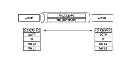
図12に示すように、3GPPで規定されているLTE方式(Release.8)の移動通信システムでは、移動局UEの無線基地局eNB#1から無線基地局eNB#2へのハンドオーバ処理が行われる際に、無線基地局eNB#1と無線基地局eNB#2との間で設定されているX2ベアラを介して、無線基地局eNB#1と無線基地局eNB#2との間で、ハンドオーバ処理に係る制御信号が送受信されるように構成されている。 As illustrated in FIG. 12, in the mobile communication system of the LTE scheme (Release.8) defined in 3GPP, a handover process of the mobile station UE from the radio base station eNB # 1 to the radio base station eNB # 2 is performed. In this case, handover processing is performed between the radio base station eNB # 1 and the radio base station eNB # 2 via the X2 bearer set between the radio base station eNB # 1 and the radio base station eNB # 2. It is comprised so that the control signal which concerns on may be transmitted / received.
図12に示すように、無線基地局eNB#1及び無線基地局#2は、X2ベアラを設定するためのX2ベアラ機能として、ネットワークレイヤ1(NW L1)機能と、ネットワークレイヤ2(NW L2)機能と、IP(Internet Protocol)レイヤ機能と、SCTP(Stream Control Transmission Protocol)レイヤ機能とを具備している。
As illustrated in FIG. 12, the radio base station eNB # 1 and the radio
LTE方式の後継の通信方式であるLTE-Advanced方式の移動通信システムでは、移動局UEと無線基地局eNBとの間に、無線基地局eNBと同様な機能を具備する「リレーノード(Relay Node)RN」を接続することができる。 In an LTE-Advanced mobile communication system, which is a successor to the LTE system, a “relay node (Relay Node) having a function similar to that of the radio base station eNB between the mobile station UE and the radio base station eNB. RN "can be connected.
しかしながら、従来の移動通信システムでは、リレーノードRNが接続された場合、どのように移動局UEのハンドオーバ処理を行うべきか規定されていないという問題点があった。 However, in the conventional mobile communication system, when the relay node RN is connected, there is a problem that it is not specified how to perform the handover process of the mobile station UE.
そこで、本発明は、上述の課題に鑑みてなされたものであり、リレーノードが接続された場合であっても、移動局のハンドオーバ処理を実現することができる移動通信システムを提供することを目的とする。 Therefore, the present invention has been made in view of the above-described problems, and an object of the present invention is to provide a mobile communication system that can realize a handover process of a mobile station even when a relay node is connected. And
本発明の第1の特徴は、移動通信システムであって、リレーノードと第1無線基地局とが無線ベアラを介して接続されており、前記第1無線基地局と第2無線基地局とが接続されており、移動局が、前記リレーノードとの間で無線ベアラを設定し該リレーノード及び前記第1無線基地局を介して通信を行っている状態と、前記第2無線基地局との間で無線ベアラを設定し該第2無線基地局を介して通信を行っている状態との間で、ハンドオーバ処理を行うように構成されており、前記ハンドオーバ処理において、前記リレーノードと前記第2無線基地局との間で無線ベアラを設定し、設定された該リレーノードと該第2無線基地局との間の無線ベアラを介して、前記ハンドオーバ処理に係る制御信号を送受信するように構成されていることを要旨とする。 A first feature of the present invention is a mobile communication system, in which a relay node and a first radio base station are connected via a radio bearer, and the first radio base station and the second radio base station are connected to each other. A state in which the mobile station is connected to the relay node and establishes a radio bearer with the relay node and performs communication via the relay node and the first radio base station; and Configured to perform a handover process with a state in which a radio bearer is set up and a communication is performed via the second radio base station. In the handover process, the relay node and the second A radio bearer is set up with a radio base station, and a control signal related to the handover process is transmitted / received through the radio bearer between the set relay node and the second radio base station. That And effect.
本発明の第1の特徴において、前記リレーノード及び前記第2無線基地局は、前記無線ベアラを設定するための機能の上位レイヤ機能として、該無線ベアラに対するキープアライブ処理を行うように構成されているレイヤ機能を具備してもよい。 In the first aspect of the present invention, the relay node and the second radio base station are configured to perform a keep alive process for the radio bearer as an upper layer function of a function for setting the radio bearer. The layer function may be provided.
本発明の第1の特徴において、前記リレーノード及び前記第2無線基地局は、前記無線ベアラを設定するための機能の上位レイヤ機能として、前記リレーノードと前記第2無線基地局との間のセキュリティ処理を行うように構成されている第1レイヤ機能と、前記第1レイヤ機能の上位レイヤ機能として、前記無線ベアラに対するキープアライブ処理を行うように構成されている第2レイヤ機能とを具備してもよい。 In the first feature of the present invention, the relay node and the second radio base station are configured as an upper layer function of a function for setting the radio bearer between the relay node and the second radio base station. A first layer function configured to perform security processing, and a second layer function configured to perform keep alive processing on the radio bearer as an upper layer function of the first layer function. May be.
本発明の第2の特徴は、移動通信システムであって、リレーノードと第1無線基地局とが無線ベアラを介して接続されており、前記第1無線基地局と第2無線基地局とがベアラを介して接続されており、移動局が、前記リレーノードとの間で無線ベアラを設定し該リレーノード及び前記第1無線基地局を介して通信を行っている第1状態と、前記第2無線基地局との間で無線ベアラを設定し該第2無線基地局を介して通信を行っている第2状態との間で、ハンドオーバ処理を行うように構成されており、前記ハンドオーバ処理において、前記リレーノードと前記第2無線基地局との間の無線ベアラ、及び、該第2無線基地局と前記第1無線基地局との間のベアラを介して、前記ハンドオーバ処理に係る制御信号を送受信するように構成されていることを要旨とする。 A second feature of the present invention is a mobile communication system, in which a relay node and a first radio base station are connected via a radio bearer, and the first radio base station and the second radio base station are connected to each other. A first state in which the mobile station is connected via a bearer, and a mobile station sets up a radio bearer with the relay node and performs communication via the relay node and the first radio base station; Configured to perform a handover process with a second state in which a radio bearer is set up with two radio base stations and communication is performed via the second radio base station. A control signal related to the handover process via a radio bearer between the relay node and the second radio base station, and a bearer between the second radio base station and the first radio base station. Configured to send and receive The gist of the Rukoto.
本発明の第2の特徴において、前記リレーノードは、前記移動局から測定報告を受信した場合、該リレーノードと前記第1無線基地局との間の無線ベアラを介して、該第1無線基地局に対して、該測定報告を転送するように構成されており、 前記第1無線基地局は、前記測定報告に基づいて、前記移動局の前記第1状態から前記第2状態へのハンドオーバ処理を開始することを決定した場合、その旨を通知するハンドオーバ要求信号を、前記ハンドオーバ処理に係る制御信号として、該第1無線基地局と前記第2無線基地局との間のベアラを介して、該第2無線基地局に送信するように構成されていてもよい。 In the second aspect of the present invention, when the relay node receives a measurement report from the mobile station, the relay node receives the first radio base station via a radio bearer between the relay node and the first radio base station. The first radio base station is configured to transfer the measurement report to a station, and based on the measurement report, the first radio base station performs handover processing from the first state to the second state of the mobile station. If it is determined to start the handover request signal to that effect, as a control signal for the handover process, via the bearer between the first radio base station and the second radio base station, It may be configured to transmit to the second radio base station.
本発明の第2の特徴において、前記リレーノードは、前記移動局の前記第1状態から前記第2状態へのハンドオーバ処理を開始することを決定した場合、その旨を通知するハンドオーバ要求信号を、前記ハンドオーバ処理に係る制御信号として、該リレーノードと前記第1無線基地局との間の無線ベアラを介して、該第1無線基地局に送信するように構成されており、前記第1無線基地局は、受信した前記ハンドオーバ要求信号を、該第1無線基地局と前記第2無線基地局との間のベアラを介して、該第2無線基地局に転送するように構成されていてもよい。 In the second aspect of the present invention, when the relay node determines to start a handover process from the first state to the second state of the mobile station, a handover request signal for notifying the fact is provided. The control signal related to the handover process is configured to be transmitted to the first radio base station via a radio bearer between the relay node and the first radio base station. The station may be configured to forward the received handover request signal to the second radio base station via a bearer between the first radio base station and the second radio base station. .
以上説明したように、本発明によれば、リレーノードが接続された場合であっても、移動局のハンドオーバ処理を実現することができる移動通信システムを提供することができる。 As described above, according to the present invention, it is possible to provide a mobile communication system capable of realizing a handover process of a mobile station even when a relay node is connected.
(本発明の第1の実施形態に係る移動通信システム)
図1乃至図5を参照して、本発明の第1の実施形態に係る移動通信システムについて説明する。
(Mobile communication system according to the first embodiment of the present invention)
A mobile communication system according to a first embodiment of the present invention will be described with reference to FIG. 1 to FIG.
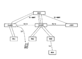
本発明に係る移動通信システムは、LTE-Advanced方式の移動通信システムであって、例えば、図1に示すように、交換局MMEと、リレーノードRN1乃至RN4と、リレーノードRN1が接続されている無線基地局DeNB(Donor eNB)1と、リレーノードRN2及びRN3が接続されている無線基地局DeNB2と、無線基地局eNB1とを具備している。
The mobile communication system according to the present invention is an LTE-Advanced mobile communication system, for example, as shown in FIG. 1, to which an exchange MME, relay nodes RN1 to RN4, and a relay node RN1 are connected. A radio base station DeNB (Donor eNB) 1, a radio base station DeNB 2 to which
ここで、無線基地局DeNB1と無線基地局DeNB2とが、X2-Cインターフェイスを介して接続されており、無線基地局DeNB2と無線基地局eNB1とが、X2-Cインターフェイスを介して接続されている。 Here, the radio base station DeNB1 and the radio base station DeNB2 are connected via the X2-C interface, and the radio base station DeNB2 and the radio base station eNB1 are connected via the X2-C interface. .
また、無線基地局DeNB1、無線基地局DeNB2及び無線基地局eNB1のそれぞれと、交換局MMEとが、S1-MMEインターフェイスを介して接続されている。 In addition, each of the radio base station DeNB1, the radio base station DeNB2, and the radio base station eNB1 is connected to the exchange MME via an S1-MME interface.
かかる移動通信システムにおいて、移動局UEは、無線基地局eNB(DeNB)及びリレーノードRNとの間で無線ベアラを設定して、無線通信を行うように構成されている。 In such a mobile communication system, the mobile station UE is configured to perform radio communication by setting a radio bearer between the radio base station eNB (DeNB) and the relay node RN.
また、かかる移動通信システムでは、図1の(2)に示すように、移動局UEが、リレーノードRN2との間で無線ベアラを設定しリレーノードRN2及び無線基地局DeNB2(第1無線基地局)を介して通信を行っている状態と、無線基地局DeNB1(第2無線基地局)との間で無線ベアラを設定し無線基地局DeNB1を介して通信を行っている状態との間で、ハンドオーバ処理を行うように構成されている。 Further, in such a mobile communication system, as shown in (2) of FIG. 1, the mobile station UE sets up a radio bearer with the relay node RN2, and sets the radio node BS2 and the radio base station DeNB2 (first radio base station). ) Between a state in which communication is performed via the wireless base station DeNB1 (second wireless base station) and a state in which communication is performed via the wireless base station DeNB1 between the wireless base station DeNB1 (second wireless base station), It is configured to perform a handover process.
また、かかるハンドオーバ処理において、リレーノードRN2と無線基地局DeNB1との間でX2-C無線ベアラ(無線ベアラ)を設定し、設定されたX2-C無線ベアラを介して、ハンドオーバ処理に係る制御信号(X2AP信号)を送受信するように構成されている。 In this handover process, an X2-C radio bearer (radio bearer) is set between the relay node RN2 and the radio base station DeNB1, and a control signal related to the handover process is set via the set X2-C radio bearer. (X2AP signal) is transmitted and received.
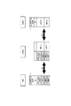
例えば、図2乃至図4に示すように、リレーノードRN2及び無線基地局DeNB1は、X2-C無線ベアラを設定するためのX2-C無線ベアラ機能として、物理(PHY)レイヤ機能と、物理(PHY)レイヤ機能の上位レイヤ機能として設けられているMAC(Media Access Control)レイヤ機能と、MACレイヤ機能の上位レイヤ機能として設けられているRLC(Radio Link Control)レイヤ機能と、RLCレイヤ機能の上位レイヤ機能として設けられているPDCP(Packet Data Convergence Protocol)レイヤ機能とを具備している。 For example, as illustrated in FIG. 2 to FIG. 4, the relay node RN2 and the radio base station DeNB1 have a physical (PHY) layer function and a physical (PHY) function as an X2-C radio bearer function for setting an X2-C radio bearer (PHY) layer function MAC (Media Access Control) layer function provided as an upper layer function, RLC (Radio Link Control) layer function provided as an MAC layer function upper layer function, and RLC layer function upper layer function PDCP (Packet Data Convergence Protocol) layer function provided as a layer function.
なお、リレーノードRN2及び無線基地局DeNB1は、PDCPレイヤ機能の上位レイヤ機能として設けられているRRC(Radio Resource Control)レイヤ機能を具備してもよい。 Note that the relay node RN2 and the radio base station DeNB1 may have an RRC (Radio Resource Control) layer function provided as an upper layer function of the PDCP layer function.
また、図2に示すように、リレーノードRN2及び無線基地局DeNB1は、X2-C無線ベアラ機能の上位レイヤ機能として、リレーノードRN2と無線基地局DeNB1との間のセキュリティ処理を行うように構成されているIPレイヤ機能(第1レイヤ機能)を具備し、IPレイヤ機能の上位レイヤ機能として、X2-C無線ベアラに対するキープアライブ処理を行うように構成されているSCTPレイヤ機能(第2レイヤ機能)とを具備してもよい。 Further, as shown in FIG. 2, the relay node RN2 and the radio base station DeNB1 are configured to perform security processing between the relay node RN2 and the radio base station DeNB1 as an upper layer function of the X2-C radio bearer function. SCTP layer function (second layer function) configured to perform keep-alive processing for the X2-C radio bearer as an upper layer function of the IP layer function. ).
或いは、図3に示すように、リレーノードRN2及び無線基地局DeNB1は、X2-C無線ベアラ機能の上位レイヤ機能として、X2-C無線ベアラに対するキープアライブ処理を行うように構成されているSCTPレイヤ機能を具備してもよい。図3の例では、リレーノードRN2及び無線基地局DeNB1は、リレーノードRN2と無線基地局DeNB2との間のセキュリティ処理を行うように構成されているIPレイヤ機能を具備していない。 Alternatively, as shown in FIG. 3, the relay node RN2 and the radio base station DeNB1 are configured to perform a keep-alive process for the X2-C radio bearer as an upper layer function of the X2-C radio bearer function. A function may be provided. In the example of FIG. 3, the relay node RN2 and the radio base station DeNB1 do not have an IP layer function configured to perform security processing between the relay node RN2 and the radio base station DeNB2.
さらに、図4に示すように、リレーノードRN2及び無線基地局DeNB1は、X2-C無線ベアラ機能の上位レイヤ機能として、X2-C無線ベアラに対するキープアライブ処理を行うように構成されているSCTPレイヤ機能、及び、リレーノードRN2と無線基地局DeNB1との間のセキュリティ処理を行うように構成されているIPレイヤ機能を具備しなくてもよい。 Furthermore, as shown in FIG. 4, the relay node RN2 and the radio base station DeNB1 are configured to perform a keep alive process for the X2-C radio bearer as an upper layer function of the X2-C radio bearer function. The function and the IP layer function configured to perform security processing between the relay node RN2 and the radio base station DeNB1 may not be provided.
以下、図5を参照して、本実施形態に係る移動通信システムにおいて、移動局UEが、リレーノードRN2との間で無線ベアラを設定しリレーノードRN2及び無線基地局DeNB2を介して通信を行っている状態から、無線基地局DeNB1との間で無線ベアラを設定し無線基地局DeNB1を介して通信を行っている状態に、ハンドオーバする動作について説明する。 Hereinafter, with reference to FIG. 5, in the mobile communication system according to the present embodiment, the mobile station UE sets up a radio bearer with the relay node RN2, and performs communication via the relay node RN2 and the radio base station DeNB2. A description will be given of an operation for performing handover from a state in which the wireless bearer is established to the wireless base station DeNB1 to a state in which communication is performed via the wireless base station DeNB1.
図5に示すように、ステップS1000において、リレーノードRN2は、移動局UEのリレーノードRN2から無線基地局DeNB1へのハンドオーバ処理を行うことを決定すると、RRCコネクション設定手順によって、無線基地局DeNB1との間で、X2-C無線ベアラを設定する。 As shown in FIG. 5, in step S1000, when the relay node RN2 determines to perform a handover process from the relay node RN2 of the mobile station UE to the radio base station DeNB1, according to the RRC connection setting procedure, Set up an X2-C radio bearer.
リレーノードRN2は、ステップS1001において、移動局UEの「UE Context」を管理しており、ステップS1002において、無線基地局DeNB1に対して、X2-C無線ベアラを介して、移動局UEのリレーノードRN2から無線基地局DeNB1へのハンドオーバを要求する「HO Request(ハンドオーバ要求信号)」を送信する。
In step S1001, the relay node RN2 manages the “UE Context” of the mobile station UE. In step S1002, the relay node RN2 communicates with the radio base station DeNB1 via the X2-C radio bearer. A “HO Request (handover request signal)” requesting a handover from the
無線基地局DeNB1は、「HO Request」を受信すると、ステップS1003において、移動局UEの「UE Context」を記憶し、ステップS1004において、リレーノードRN2に対して、X2-C無線ベアラを介して、「HO Request Ack(ハンドオーバ要求確認信号)」を送信する。 When receiving the “HO Request”, the radio base station DeNB1 stores “UE Context” of the mobile station UE in Step S1003. In Step S1004, the radio base station DeNB1 passes the X2-C radio bearer to the relay node RN2. “HO Request Ack (handover request confirmation signal)” is transmitted.
ステップS1005において、リレーノードRN2は、移動局UEに対して、RRCレイヤ機能によって、無線基地局DeNB1にハンドオーバするように指示する「HO Command(ハンドオーバ指示信号)」を送信する。 In Step S1005, the relay node RN2 transmits “HO Command (handover instruction signal)” instructing the mobile station UE to perform handover to the radio base station DeNB1 by the RRC layer function.
ステップS1006において、移動局UEは、RRCレイヤ機能によって、無線基地局DeNB1に対して、「HO Complete(ハンドオーバ完了信号)」を送信する。 In step S1006, the mobile station UE transmits “HO Complete (handover completion signal)” to the radio base station DeNB1 by the RRC layer function.
ステップS1007において、無線基地局DeNB1は、S1-MMEインターフェイスを介して、交換局MMEに対して、「Path Swith Request(パス切替要求信号)」を送信する。 In Step S1007, the radio base station DeNB1 transmits a “Path Switch Request (path switching request signal)” to the switching center MME via the S1-MME interface.
ステップS1008において、交換局MMEは、S1-MMEインターフェイスを介して、無線基地局DeNB1に対して、「Path Swith Request Ack(パス切替要求確認信号)」を送信すると共に、移動局UE宛ての信号の転送先を、リレーノードRN2から無線基地局DeNB1に切り替える。 In step S1008, the mobile switching center MME transmits a “Path Switch Request Ack (path switching request confirmation signal)” to the radio base station DeNB1 via the S1-MME interface, and also transmits a signal addressed to the mobile station UE. The transfer destination is switched from the relay node RN2 to the radio base station DeNB1.
ステップS1009において、無線基地局DeNB1は、X2-C無線ベアラを介して、リレーノードRN2に対して、「UE Context Release」を送信し、リレーノードRN2は、「UE Context Release」に応じて、移動局UEの「UE Context」の管理を終了する。 In step S1009, the radio base station DeNB1 transmits “UE Context Release” to the relay node RN2 via the X2-C radio bearer, and the relay node RN2 moves according to the “UE Context Release”. Management of the “UE Context” of the station UE is terminated.
なお、図5において、リレーノードRN2と無線基地局DeNB1とが入れ替わってもよい。 In FIG. 5, the relay node RN2 and the radio base station DeNB1 may be interchanged.
本実施形態に係る移動通信システムによれば、LTE方式の移動通信システムで用いられていた各装置のプロトコルスタックに対して、大きな改修を施すことなく、リレーノードRNが関連するハンドオーバ処理を実現することができる。 According to the mobile communication system according to the present embodiment, the handover process related to the relay node RN is realized without significantly modifying the protocol stack of each device used in the LTE mobile communication system. be able to.
(本発明の第2の実施形態に係る移動通信システム)
図6及び図7を参照して、本発明の第2の実施形態に係る移動通信システムについて説明する。以下、本発明の第2の実施形態に係る移動通信システムについて、上述の第1の実施形態に係る移動通信システムとの相違点に着目して説明する。
(Mobile communication system according to the second embodiment of the present invention)
With reference to FIG.6 and FIG.7, the mobile communication system which concerns on the 2nd Embodiment of this invention is demonstrated. Hereinafter, the mobile communication system according to the second embodiment of the present invention will be described by focusing on differences from the above-described mobile communication system according to the first embodiment.
本実施形態に係る移動通信システムでは、上述のハンドオーバ処理において、リレーノードRN2と無線基地局DeNB2との間のX2-C無線ベアラ(Unインターフェイス)、及び、無線基地局DeNB2と無線基地局DeNB1との間のベアラ(X2-Cインターフェイス)を介して、ハンドオーバ処理に係る制御信号を送受信するように構成されている。 In the mobile communication system according to the present embodiment, in the above handover process, the X2-C radio bearer (Un interface) between the relay node RN2 and the radio base station DeNB2, and the radio base station DeNB2 and the radio base station DeNB1 The control signal related to the handover process is transmitted and received via a bearer (X2-C interface) between the two.
具体的には、図6に示すように、リレーノードRN2は、無線基地局DeNB2との間のX2-C無線ベアラ(Unインターフェイス)を設定するためのX2-C無線ベアラ機能として、物理(PHY)レイヤ機能と、物理(PHY)レイヤ機能の上位レイヤ機能として設けられているMACレイヤ機能と、MACレイヤ機能の上位レイヤ機能として設けられているRLCレイヤ機能と、RLCレイヤ機能の上位レイヤ機能として設けられているPDCPレイヤ機能とを具備している。 Specifically, as illustrated in FIG. 6, the relay node RN2 uses a physical (PHY) as an X2-C radio bearer function for setting up an X2-C radio bearer (Un interface) with the radio base station DeNB2. ) Layer function, MAC layer function provided as upper layer function of physical (PHY) layer function, RLC layer function provided as upper layer function of MAC layer function, and upper layer function of RLC layer function And the provided PDCP layer function.
なお、リレーノードRN2は、PDCPレイヤ機能の上位レイヤ機能として設けられているRRCレイヤ機能を具備してもよい。 Note that the relay node RN2 may include an RRC layer function provided as an upper layer function of the PDCP layer function.
また、図6に示すように、リレーノードRN2は、X2-C無線ベアラ機能の上位レイヤ機能として、リレーノードRN2と無線基地局DeNB2との間のセキュリティ処理を行うように構成されているIPレイヤ機能を具備し、IPレイヤ機能の上位レイヤ機能として、X2-C無線ベアラに対するキープアライブ処理を行うように構成されているSCTPレイヤ機能を具備してもよい。 Further, as shown in FIG. 6, the relay node RN2 is configured to perform security processing between the relay node RN2 and the radio base station DeNB2 as an upper layer function of the X2-C radio bearer function. And an SCTP layer function configured to perform keep-alive processing for the X2-C radio bearer as an upper layer function of the IP layer function.
また、リレーノードRN2は、SCTPレイヤ機能の上位レイヤ機能として、ハンドオーバ処理に係る制御信号を送受信するように構成されているX2APレイヤ機能を具備してもよい。 Further, the relay node RN2 may include an X2AP layer function configured to transmit and receive a control signal related to the handover process as an upper layer function of the SCTP layer function.
また、無線基地局DeNB2は、リレーノードRN2との間のX2-C無線ベアラ(Unインターフェイス)を設定するためのX2-C無線ベアラ機能と、無線基地局DeNB1との間のベアラ(X2-Cインターフェイス)を設定するためのベアラ機能とを具備している。 The radio base station DeNB2 also configures an X2-C radio bearer function for setting an X2-C radio bearer (Un interface) with the relay node RN2, and a bearer (X2-C with the radio base station DeNB1). A bearer function for setting the interface).
ここで、無線基地局DeNB2は、ベアラ機能として、ネットワークレイヤ1(NW L1)機能と、ネットワークレイヤ2(NW L2)機能とを具備している。 Here, the radio base station DeNB2 has a network layer 1 (NW L1) function and a network layer 2 (NW L2) function as bearer functions.
また、無線基地局DeNB2は、X2-C無線ベアラ機能及びベアラ機能の上位レイヤ機能として設けられているIPレイヤ機能と、IPレイヤ機能の上位レイヤ機能として設けられているSCTP機能と、SCTPレイヤ機能の上位レイヤ機能として設けられているX2APレイヤ機能とを具備している。 The radio base station DeNB2 includes an X2-C radio bearer function and an IP layer function provided as an upper layer function of the bearer function, an SCTP function provided as an upper layer function of the IP layer function, and an SCTP layer function. X2AP layer function provided as a higher layer function.
さらに、無線基地局DeNB1は、無線基地局DeNB2との間のベアラを設定するためのベアラ機能として、ネットワークレイヤ1(NW L1)機能と、ネットワークレイヤ2(NW L2)機能とを具備している。 Furthermore, the radio base station DeNB1 has a network layer 1 (NW L1) function and a network layer 2 (NW L2) function as bearer functions for setting up a bearer with the radio base station DeNB2. .
また、無線基地局DeNB1は、かかるベアラ機能の上位レイヤ機能として設けられているIPレイヤ機能と、IPレイヤ機能の上位レイヤ機能として設けられているSCTP機能と、SCTPレイヤ機能の上位レイヤ機能として設けられているX2APレイヤ機能とを具備している。 The radio base station DeNB1 is provided as an IP layer function provided as an upper layer function of the bearer function, an SCTP function provided as an upper layer function of the IP layer function, and an upper layer function of the SCTP layer function. X2AP layer function.
以下、図7を参照して、本実施形態に係る移動通信システムにおいて、移動局UEが、リレーノードRN2との間で無線ベアラを設定しリレーノードRN2及び無線基地局DeNB2を介して通信を行っている状態から、無線基地局DeNB1との間で無線ベアラを設定し無線基地局DeNB1を介して通信を行っている状態に、ハンドオーバする動作について説明する。 Hereinafter, with reference to FIG. 7, in the mobile communication system according to the present embodiment, the mobile station UE sets up a radio bearer with the relay node RN2, and performs communication via the relay node RN2 and the radio base station DeNB2. A description will be given of an operation for performing handover from a state in which the wireless bearer is established to the wireless base station DeNB1 to a state in which communication is performed via the wireless base station DeNB1.
図7に示すように、リレーノードRN2は、ステップS2000において、移動局UEの「UE Context」を管理しており、ステップS2001において、無線基地局DeNB2に対して、X2-C無線ベアラを介して、移動局UEのリレーノードRN2から無線基地局DeNB1へのハンドオーバを要求する「HO Request(ハンドオーバ要求信号)」を送信する。 As shown in FIG. 7, the relay node RN2 manages the “UE Context” of the mobile station UE in step S2000, and in step S2001, the radio base station DeNB2 via the X2-C radio bearer. The mobile station UE transmits a “HO Request (handover request signal)” requesting handover from the relay node RN2 of the mobile station UE to the radio base station DeNB1.
無線基地局DeNB2は、X2APレイヤ機能において、「HO Request」を受信すると、ステップS2002において、移動局UEの「UE Context」を記憶し、ステップS2003において、かかる「HO Request」を、X2-C無線ベアラを介して、無線基地局DeNB1に転送する。 When receiving the “HO Request” in the X2AP layer function, the radio base station DeNB2 stores “UE Context” of the mobile station UE in Step S2002, and in Step S2003, stores the “HO Request” in the X2-C radio. The data is transferred to the radio base station DeNB1 via the bearer.
無線基地局DeNB1は、「HO Request」を受信すると、ステップS2004において、移動局UEの「UE Context」を記憶し、ステップS2005において、無線基地局DeNB2に対して、X2-C無線ベアラを介して、「HO Request Ack(ハンドオーバ要求確認信号)」を送信する。 When receiving the “HO Request”, the radio base station DeNB1 stores “UE Context” of the mobile station UE in step S2004, and in step S2005, the radio base station DeNB1 via the X2-C radio bearer , “HO Request Ack (handover request confirmation signal)” is transmitted.
無線基地局DeNB2は、X2APレイヤ機能において、「HO Request Ack」を受信すると、ステップS2006において、かかる「HO Request Ack」を、X2-C無線ベアラを介して、リレーノードRN2に転送する。 When receiving the “HO Request Ack” in the X2AP layer function, the radio base station DeNB2 transfers the “HO Request Ack” to the relay node RN2 via the X2-C radio bearer in Step S2006.
ステップS2007において、リレーノードRN2は、移動局UEに対して、RRCレイヤ機能によって、無線基地局DeNB1にハンドオーバするように指示する「HO Command(ハンドオーバ指示信号)」を送信する。 In step S2007, the relay node RN2 transmits “HO Command (handover instruction signal)” instructing the mobile station UE to perform handover to the radio base station DeNB1 by the RRC layer function.
ステップS2008において、移動局UEは、RRCレイヤ機能によって、無線基地局DeNB1に対して、「HO Complete(ハンドオーバ完了信号)」を送信する。 In step S2008, the mobile station UE transmits “HO Complete (handover completion signal)” to the radio base station DeNB1 by the RRC layer function.
ステップS2009において、無線基地局DeNB1は、S1-MMEインターフェイスを介して、交換局MMEに対して、「Path Swith Request(パス切替要求信号)」を送信する。 In step S2009, the radio base station DeNB1 transmits a “Path Switch Request (path switching request signal)” to the switching center MME via the S1-MME interface.
ステップS2010において、交換局MMEは、S1-MMEインターフェイスを介して、無線基地局DeNB1に対して、「Path Swith Request Ack(パス切替要求確認信号)」を送信すると共に、移動局UE宛ての信号の転送先を、リレーノードRN2から無線基地局DeNB1に切り替える。 In step S2010, the mobile switching center MME transmits a “Path Switch Request Ack (path switching request confirmation signal)” to the radio base station DeNB1 via the S1-MME interface, and also transmits a signal addressed to the mobile station UE. The transfer destination is switched from the relay node RN2 to the radio base station DeNB1.
ステップS2011において、無線基地局DeNB1は、X2-C無線ベアラを介して、無線基地局DeNB2に対して、「UE Context Release」を送信し、ステップS2012において、無線基地局DeNB2は、X2APレイヤ機能において、リレーノードRN2に対して、X2-C無線ベアラを介して、「UE Context Release」を転送し、リレーノードRN2は、「UE Context Release」に応じて、移動局UEの「UE Context」の管理を終了する。 In step S2011, the radio base station DeNB1 transmits “UE Context Release” to the radio base station DeNB2 via the X2-C radio bearer. In step S2012, the radio base station DeNB2 performs the X2AP layer function. The UE forwards “UE Context Release” to the relay node RN2 via the X2-C radio bearer, and the relay node RN2 manages the “UE Context” of the mobile station UE in accordance with the “UE Context Release”. Exit.
なお、図7において、リレーノードRN2と無線基地局DeNB1とが入れ替わってもよい。 In FIG. 7, the relay node RN2 and the radio base station DeNB1 may be interchanged.
上述のように、無線基地局DeNB2におけるX2APレイヤ機能は、リレーノートRN2と無線基地局DeNB2との間におけるハンドオーバ処理に係る制御信号(X2AP信号)と、無線基地局DeNB1と無線基地局DeNB2との間におけるハンドオーバ処理に係る制御信号(X2AP信号)とを変換するように構成されている。 As described above, the X2AP layer function in the radio base station DeNB2 is the control signal (X2AP signal) related to the handover process between the relay note RN2 and the radio base station DeNB2, and between the radio base station DeNB1 and the radio base station DeNB2. It is configured to convert a control signal (X2AP signal) related to the handover process between them.
また、無線基地局DeNB2におけるX2APレイヤ機能は、リレーノートRN2と無線基地局DeNB2との間で用いられている移動局IDと、無線基地局DeNB1と無線基地局DeNB2との間で用いられている移動局IDとを関連付けて管理するように構成されている。 The X2AP layer function in the radio base station DeNB2 is used between the mobile station ID used between the relay note RN2 and the radio base station DeNB2, and between the radio base station DeNB1 and the radio base station DeNB2. The mobile station ID is configured to be associated and managed.
(本発明の第3の実施形態に係る移動通信システム)
図8及び図9を参照して、本発明の第3の実施形態に係る移動通信システムについて説明する。以下、本発明の第3の実施形態に係る移動通信システムについて、上述の第1の実施形態に係る移動通信システムとの相違点に着目して説明する。
(Mobile communication system according to the third embodiment of the present invention)
With reference to FIG.8 and FIG.9, the mobile communication system which concerns on the 3rd Embodiment of this invention is demonstrated. Hereinafter, the mobile communication system according to the third embodiment of the present invention will be described by focusing on differences from the above-described mobile communication system according to the first embodiment.
本実施形態に係る移動通信システムでは、上述のハンドオーバ処理において、リレーノードRN2と無線基地局DeNB2との間のX2-C無線ベアラ(Unインターフェイス)、及び、無線基地局DeNB2と無線基地局DeNB1との間のベアラ(X2-Cインターフェイス)を介して、ハンドオーバ処理に係る制御信号を送受信するように構成されている。 In the mobile communication system according to the present embodiment, in the above handover process, the X2-C radio bearer (Un interface) between the relay node RN2 and the radio base station DeNB2, and the radio base station DeNB2 and the radio base station DeNB1 The control signal related to the handover process is transmitted and received via a bearer (X2-C interface) between the two.
具体的には、図8に示すように、リレーノードRN2は、無線基地局DeNB2との間のX2-C無線ベアラ(Unインターフェイス)を設定するためのX2-C無線ベアラ機能として、物理(PHY)レイヤ機能と、物理(PHY)レイヤ機能の上位レイヤ機能として設けられているMACレイヤ機能と、MACレイヤ機能の上位レイヤ機能として設けられているRLCレイヤ機能と、RLCレイヤ機能の上位レイヤ機能として設けられているPDCPレイヤ機能とを具備している。 Specifically, as illustrated in FIG. 8, the relay node RN2 uses a physical (PHY) as an X2-C radio bearer function for setting up an X2-C radio bearer (Un interface) with the radio base station DeNB2. ) Layer function, MAC layer function provided as upper layer function of physical (PHY) layer function, RLC layer function provided as upper layer function of MAC layer function, and upper layer function of RLC layer function And the provided PDCP layer function.
なお、リレーノードRN2は、PDCPレイヤ機能の上位レイヤ機能として設けられているRRCレイヤ機能を具備してもよい。 Note that the relay node RN2 may include an RRC layer function provided as an upper layer function of the PDCP layer function.
また、図8に示すように、リレーノードRN2は、移動局UEにおけるRRCレイヤ機能のプロキシとして動作するように構成されており、X2-C無線ベアラ機能の上位レイヤ機能として、リレーノードRN2と無線基地局DeNB2との間のセキュリティ処理を行うように構成されているIPレイヤ機能や、X2-C無線ベアラに対するキープアライブ処理を行うように構成されているSCTPレイヤ機能や、ハンドオーバ処理に係る制御信号を送受信するように構成されているX2APレイヤ機能を具備していない。 Also, as shown in FIG. 8, the relay node RN2 is configured to operate as a proxy for the RRC layer function in the mobile station UE, and as a higher layer function of the X2-C radio bearer function, the relay node RN2 and the radio node IP layer function configured to perform security processing with the base station DeNB2, SCTP layer function configured to perform keep-alive processing for the X2-C radio bearer, and control signal related to handover processing Does not have an X2AP layer function configured to transmit and receive.
また、無線基地局DeNB2は、リレーノードRN2との間のX2-C無線ベアラ(Unインターフェイス)を設定するためのX2-C無線ベアラ機能と、無線基地局DeNB1との間のベアラ(X2-Cインターフェイス)を設定するためのベアラ機能とを具備している。 The radio base station DeNB2 also configures an X2-C radio bearer function for setting an X2-C radio bearer (Un interface) with the relay node RN2, and a bearer (X2-C with the radio base station DeNB1). A bearer function for setting the interface).
ここで、無線基地局DeNB2は、ベアラ機能として、ネットワークレイヤ1(NW L1)機能と、ネットワークレイヤ2(NW L2)機能とを具備している。 Here, the radio base station DeNB2 has a network layer 1 (NW L1) function and a network layer 2 (NW L2) function as bearer functions.
また、無線基地局DeNB2は、X2-C無線ベアラ機能及びベアラ機能の上位レイヤ機能として設けられているIPレイヤ機能と、IPレイヤ機能の上位レイヤ機能として設けられているSCTP機能と、SCTPレイヤ機能の上位レイヤ機能として設けられているX2APレイヤ機能とを具備している。 The radio base station DeNB2 includes an X2-C radio bearer function and an IP layer function provided as an upper layer function of the bearer function, an SCTP function provided as an upper layer function of the IP layer function, and an SCTP layer function. X2AP layer function provided as a higher layer function.
さらに、無線基地局DeNB1は、無線基地局DeNB2との間のベアラ(X2-Cインターフェイス)を設定するためのベアラ機能として、ネットワークレイヤ1(NW L1)機能と、ネットワークレイヤ2(NW L2)機能とを具備している。 Furthermore, the radio base station DeNB1 has a network layer 1 (NW L1) function and a network layer 2 (NW L2) function as bearer functions for setting up a bearer (X2-C interface) with the radio base station DeNB2. It is equipped with.
また、無線基地局DeNB1は、かかるベアラ機能の上位レイヤ機能として設けられているIPレイヤ機能と、IPレイヤ機能の上位レイヤ機能として設けられているSCTP機能と、SCTPレイヤ機能の上位レイヤ機能として設けられているX2APレイヤ機能とを具備している。 The radio base station DeNB1 is provided as an IP layer function provided as an upper layer function of the bearer function, an SCTP function provided as an upper layer function of the IP layer function, and an upper layer function of the SCTP layer function. X2AP layer function.
以下、図9を参照して、本実施形態に係る移動通信システムにおいて、移動局UEが、リレーノードRN2との間で無線ベアラを設定しリレーノードRN2及び無線基地局DeNB2を介して通信を行っている状態から、無線基地局DeNB1との間で無線ベアラを設定し無線基地局DeNB1を介して通信を行っている状態に、ハンドオーバする動作について説明する。 Hereinafter, with reference to FIG. 9, in the mobile communication system according to the present embodiment, the mobile station UE sets up a radio bearer with the relay node RN2, and performs communication via the relay node RN2 and the radio base station DeNB2. A description will be given of an operation for performing handover from a state in which the wireless bearer is established to the wireless base station DeNB1 to a state in which communication is performed via the wireless base station DeNB1.
図9に示すように、リレーノードRN2は、ステップS3000において、移動局UEから「Measurement Report(測定報告)」を受信すると、ステップS3001において、管理している移動局UEの「UE Context」を取得して、ステップS3002において、RRCレイヤ機能によって、かかる移動局UEの「UE Context」を含む「Measurement Report」を無線基地局DeNB2に転送する。 As illustrated in FIG. 9, when the relay node RN2 receives “Measurement Report (measurement report)” from the mobile station UE in step S3000, the relay node RN2 acquires “UE Context” of the managed mobile station UE in step S3001. In step S3002, the “Measurement Report” including the “UE Context” of the mobile station UE is transferred to the radio base station DeNB2 by the RRC layer function.
無線基地局DeNB2は、受信した「Measurement Report」に基づいて、移動局UEのリレーノードRN2から無線基地局DeNB1へのハンドオーバ処理を行うことを決定し、ステップS3003において、移動局UEの「UE Context」を記憶し、ステップS3004において、移動局UEのリレーノードRN2から無線基地局DeNB1へのハンドオーバを要求する「HO Request(ハンドオーバ要求信号)」を、無線基地局DeNB1に対して、X2-C無線ベアラを介して送信する。 Based on the received “Measurement Report”, the radio base station DeNB2 determines to perform a handover process from the relay node RN2 of the mobile station UE to the radio base station DeNB1, and in step S3003, the “UE Context of the mobile station UE In step S3004, “HO Request (handover request signal)” for requesting handover from the relay node RN2 of the mobile station UE to the radio base station DeNB1 is transmitted to the radio base station DeNB1 by the X2-C radio. Send via bearer.
無線基地局DeNB1は、「HO Request」を受信すると、ステップS3005において、移動局UEの「UE Context」を記憶し、ステップS3006において、無線基地局DeNB2に対して、X2-C無線ベアラを介して、「HO Request Ack(ハンドオーバ要求確認信号)」を送信する。 When receiving the “HO Request”, the radio base station DeNB1 stores “UE Context” of the mobile station UE in step S3005, and in step S3006, the radio base station DeNB2 via the X2-C radio bearer. , “HO Request Ack (handover request confirmation signal)” is transmitted.
無線基地局DeNB2は、「HO Request Ack」を受信すると、ステップS3007において、リレーノードRN2に対して、RRCレイヤ機能によって、無線基地局DeNB1にハンドオーバするように指示する「HO Command(ハンドオーバ指示信号)」を送信する。 When receiving the “HO Request Ack”, the radio base station DeNB2 instructs the relay node RN2 to perform handover to the radio base station DeNB1 by the RRC layer function in Step S3007 (“HO Command”). ".
ステップS3008において、リレーノードRN2は、移動局UEに対して、RRCレイヤ機能によって、受信した「HO Command」を転送する。 In step S3008, the relay node RN2 transfers the received “HO Command” to the mobile station UE by the RRC layer function.
ステップS3009において、移動局UEは、RRCレイヤ機能によって、無線基地局DeNB1に対して、「HO Complete(ハンドオーバ完了信号)」を送信する。 In step S3009, the mobile station UE transmits “HO Complete (handover completion signal)” to the radio base station DeNB1 by the RRC layer function.
ステップS3010において、無線基地局DeNB1は、S1-MMEインターフェイスを介して、交換局MMEに対して、「Path Swith Request(パス切替要求信号)」を送信する。 In step S3010, the radio base station DeNB1 transmits a “Path Switch Request (path switching request signal)” to the switching center MME via the S1-MME interface.
ステップS3011において、交換局MMEは、S1-MMEインターフェイスを介して、無線基地局DeNB1に対して、「Path Swith Request Ack(パス切替要求確認信号)」を送信すると共に、移動局UE宛ての信号の転送先を、リレーノードRN2から無線基地局DeNB1に切り替える。 In step S3011, the mobile switching center MME transmits a “Path Switch Request Ack (path switching request confirmation signal)” to the radio base station DeNB1 via the S1-MME interface, and also transmits a signal addressed to the mobile station UE. The transfer destination is switched from the relay node RN2 to the radio base station DeNB1.
ステップS3012において、無線基地局DeNB1は、X2-C無線ベアラを介して、無線基地局DeNB2に対して、「UE Context Release」を送信し、ステップS3013において、無線基地局DeNB2は、RRCレイヤ機能において、リレーノードRN2に対して、「RRC Connection Release」を転送し、リレーノードRN2は、「RRC Connection Release」に応じて、移動局UEの「UE Context」の管理を終了する。 In step S3012, the radio base station DeNB1 transmits “UE Context Release” to the radio base station DeNB2 via the X2-C radio bearer. In step S3013, the radio base station DeNB2 Then, the “RRC Connection Release” is transferred to the relay node RN2, and the relay node RN2 ends the management of the “UE Context” of the mobile station UE according to the “RRC Connection Release”.
(本発明の第4の実施形態に係る移動通信システム)
図10及び図11を参照して、本発明の第4の実施形態に係る移動通信システムについて説明する。以下、本発明の第4の実施形態に係る移動通信システムについて、上述の第1の実施形態に係る移動通信システムとの相違点に着目して説明する。
(Mobile communication system according to the fourth embodiment of the present invention)
With reference to FIG.10 and FIG.11, the mobile communication system which concerns on the 4th Embodiment of this invention is demonstrated. Hereinafter, the mobile communication system according to the fourth embodiment of the present invention will be described by focusing on differences from the above-described mobile communication system according to the first embodiment.
本実施形態に係る移動通信システムでは、上述のハンドオーバ処理において、リレーノードRN2と無線基地局DeNB2との間のX2-C無線ベアラ(Unインターフェイス)、及び、無線基地局DeNB2と無線基地局DeNB1との間のベアラ(X2-Cインターフェイス)を介して、ハンドオーバ処理に係る制御信号を送受信するように構成されている。 In the mobile communication system according to the present embodiment, in the above handover process, the X2-C radio bearer (Un interface) between the relay node RN2 and the radio base station DeNB2, and the radio base station DeNB2 and the radio base station DeNB1 The control signal related to the handover process is transmitted and received via a bearer (X2-C interface) between the two.
具体的には、図10に示すように、リレーノードRN2は、無線基地局DeNB2との間のX2-C無線ベアラ(Unインターフェイス)を設定するためのX2-C無線ベアラ機能として、物理(PHY)レイヤ機能と、物理(PHY)レイヤ機能の上位レイヤ機能として設けられているMACレイヤ機能と、MACレイヤ機能の上位レイヤ機能として設けられているRLCレイヤ機能と、RLCレイヤ機能の上位レイヤ機能として設けられているPDCPレイヤ機能とを具備している。 Specifically, as illustrated in FIG. 10, the relay node RN2 uses a physical (PHY) as an X2-C radio bearer function for setting an X2-C radio bearer (Un interface) with the radio base station DeNB2. ) Layer function, MAC layer function provided as upper layer function of physical (PHY) layer function, RLC layer function provided as upper layer function of MAC layer function, and upper layer function of RLC layer function And the provided PDCP layer function.
なお、リレーノードRN2は、PDCPレイヤ機能の上位レイヤ機能として設けられているRRCレイヤ機能を具備してもよい。 Note that the relay node RN2 may include an RRC layer function provided as an upper layer function of the PDCP layer function.
また、図10に示すように、リレーノードRN2は、X2-C無線ベアラ機能の上位レイヤ機能として、リレーノードRN2と無線基地局DeNB2との間のセキュリティ処理を行うように構成されているIPレイヤ機能を具備し、IPレイヤ機能の上位レイヤ機能として、X2-C無線ベアラに対するキープアライブ処理を行うように構成されているSCTPレイヤ機能を具備してもよい。 Also, as shown in FIG. 10, the relay node RN2 is configured to perform a security process between the relay node RN2 and the radio base station DeNB2 as an upper layer function of the X2-C radio bearer function. And an SCTP layer function configured to perform keep-alive processing for the X2-C radio bearer as an upper layer function of the IP layer function.
また、リレーノードRN2は、SCTPレイヤ機能の上位レイヤ機能として、ハンドオーバ処理に係る制御信号を送受信するように構成されているX2APレイヤ機能を具備してもよい。 Further, the relay node RN2 may include an X2AP layer function configured to transmit and receive a control signal related to the handover process as an upper layer function of the SCTP layer function.
また、無線基地局DeNB2は、リレーノードRN2との間のX2-C無線ベアラ(Unインターフェイス)を設定するためのX2-C無線ベアラ機能と、無線基地局DeNB1との間のベアラ(X2-Cインターフェイス)を設定するためのベアラ機能とを具備している。 The radio base station DeNB2 also configures an X2-C radio bearer function for setting an X2-C radio bearer (Un interface) with the relay node RN2, and a bearer (X2-C with the radio base station DeNB1). A bearer function for setting the interface).
ここで、無線基地局DeNB2は、ベアラ機能として、ネットワークレイヤ1(NW L1)機能と、ネットワークレイヤ2(NW L2)機能とを具備している。 Here, the radio base station DeNB2 has a network layer 1 (NW L1) function and a network layer 2 (NW L2) function as bearer functions.
また、無線基地局DeNB2は、X2-C無線ベアラ機能及びベアラ機能の上位レイヤ機能として、IPレイヤ機能を具備しているが、IPレイヤ機能の上位レイヤ機能として、SCTP機能やX2APレイヤ機能を具備していない。 The radio base station DeNB2 has an IP layer function as an upper layer function of the X2-C radio bearer function and a bearer function, but has an SCTP function and an X2AP layer function as an upper layer function of the IP layer function. Not done.
さらに、無線基地局DeNB1は、無線基地局DeNB2との間のベアラを設定するためのベアラ機能として、ネットワークレイヤ1(NW L1)機能と、ネットワークレイヤ2(NW L2)機能とを具備している。 Furthermore, the radio base station DeNB1 has a network layer 1 (NW L1) function and a network layer 2 (NW L2) function as bearer functions for setting up a bearer with the radio base station DeNB2. .
また、無線基地局DeNB1は、かかるベアラ機能の上位レイヤ機能として設けられているIPレイヤ機能と、IPレイヤ機能の上位レイヤ機能として設けられているSCTP機能と、SCTPレイヤ機能の上位レイヤ機能として設けられているX2APレイヤ機能とを具備している。 The radio base station DeNB1 is provided as an IP layer function provided as an upper layer function of the bearer function, an SCTP function provided as an upper layer function of the IP layer function, and an upper layer function of the SCTP layer function. X2AP layer function.
以下、図11を参照して、本実施形態に係る移動通信システムにおいて、移動局UEが、リレーノードRN2との間で無線ベアラを設定しリレーノードRN2及び無線基地局DeNB2を介して通信を行っている状態から、無線基地局DeNB1との間で無線ベアラを設定し無線基地局DeNB1を介して通信を行っている状態に、ハンドオーバする動作について説明する。 Hereinafter, with reference to FIG. 11, in the mobile communication system according to the present embodiment, the mobile station UE sets up a radio bearer with the relay node RN2, and performs communication via the relay node RN2 and the radio base station DeNB2. A description will be given of an operation for performing handover from a state in which the wireless bearer is established to the wireless base station DeNB1 to a state in which communication is performed via the wireless base station DeNB1.
図11に示すように、リレーノードRN2は、ステップS4000において、移動局UEの「UE Context」を管理しており、ステップS4001において、無線基地局DeNB2に対して、X2-C無線ベアラを介して、移動局UEのリレーノードRN2から無線基地局DeNB1へのハンドオーバを要求する「HO Request(ハンドオーバ要求信号)」を送信する。 As illustrated in FIG. 11, the relay node RN2 manages the “UE Context” of the mobile station UE in step S4000. In step S4001, the relay node RN2 transmits the radio base station DeNB2 via the X2-C radio bearer. The mobile station UE transmits a “HO Request (handover request signal)” requesting handover from the relay node RN2 of the mobile station UE to the radio base station DeNB1.
無線基地局DeNB2は、IPレイヤ機能によって、ステップS4002において、「HO Request」を受信すると、ステップS4003において、かかる「HO Request」を、X2-C無線ベアラを介して、無線基地局DeNB1に転送する。 When receiving the “HO Request” in step S4002 by the IP layer function, the radio base station DeNB2 transfers the “HO Request” to the radio base station DeNB1 via the X2-C radio bearer in step S4003. .
無線基地局DeNB1は、「HO Request」を受信すると、ステップS4004において、移動局UEの「UE Context」を記憶し、ステップS4005において、無線基地局DeNB2に対して、X2-C無線ベアラを介して、「HO Request Ack(ハンドオーバ要求確認信号)」を送信する。 When receiving the “HO Request”, the radio base station DeNB1 stores “UE Context” of the mobile station UE in Step S4004. In Step S4005, the radio base station DeNB1 passes the X2-C radio bearer to the radio base station DeNB2. , “HO Request Ack (handover request confirmation signal)” is transmitted.
無線基地局DeNB2は、IPレイヤ機能において、「HO Request Ack」を受信すると、ステップS4006において、かかる「HO Request Ack」を、X2-C無線ベアラを介して、リレーノードRN2に転送する。 When receiving the “HO Request Ack” in the IP layer function, the radio base station DeNB2 transfers the “HO Request Ack” to the relay node RN2 via the X2-C radio bearer in Step S4006.
ステップS4007において、リレーノードRN2は、移動局UEに対して、RRCレイヤ機能によって、無線基地局DeNB1にハンドオーバするように指示する「HO Command(ハンドオーバ指示信号)」を送信する。 In step S4007, the relay node RN2 transmits “HO Command (handover instruction signal)” instructing the mobile station UE to perform handover to the radio base station DeNB1 by the RRC layer function.
ステップS4008において、移動局UEは、RRCレイヤ機能によって、無線基地局DeNB1に対して、「HO Complete(ハンドオーバ完了信号)」を送信する。 In step S4008, the mobile station UE transmits “HO Complete (handover completion signal)” to the radio base station DeNB1 by the RRC layer function.
ステップS4009において、無線基地局DeNB1は、S1-MMEインターフェイスを介して、交換局MMEに対して、「Path Swith Request(パス切替要求信号)」を送信する。 In step S4009, the radio base station DeNB1 transmits a “Path Switch Request (path switching request signal)” to the switching center MME via the S1-MME interface.
ステップS4010において、交換局MMEは、S1-MMEインターフェイスを介して、無線基地局DeNB1に対して、「Path Swith Request Ack(パス切替要求確認信号)」を送信すると共に、移動局UE宛ての信号の転送先を、リレーノードRN2から無線基地局DeNB1に切り替える。 In step S4010, the switching center MME transmits a “Path Switch Request Ack (path switching request confirmation signal)” to the radio base station DeNB1 via the S1-MME interface, and transmits a signal addressed to the mobile station UE. The transfer destination is switched from the relay node RN2 to the radio base station DeNB1.
ステップS4011において、無線基地局DeNB1は、X2-C無線ベアラを介して、無線基地局DeNB2に対して、「UE Context Release」を送信し、無線基地局DeNB2は、Iレイヤ機能によって、ステップS4012において、「UE Context Release」を受信すると、ステップS4013において、リレーノードRN2に対して、X2-C無線ベアラを介して、「UE Context Release」を転送し、リレーノードRN2は、「UE Context Release」に応じて、移動局UEの「UE Context」の管理を終了する。
In step S4011, the radio base station DeNB1 transmits “UE Context Release” to the radio base station DeNB2 via the X2-C radio bearer, and the radio base station DeNB2 performs the I-layer function in step S4012. When “UE Context Release” is received, in step S 4013, “UE Context Release” is transferred to relay
なお、上述の移動局UEやリレーノードRNや無線基地局eNBや交換局MMEの動作は、ハードウェアによって実施されてもよいし、プロセッサによって実行されるソフトウェアモジュールによって実施されてもよいし、両者の組み合わせによって実施されてもよい。 Note that the operations of the mobile station UE, the relay node RN, the radio base station eNB, and the switching center MME described above may be performed by hardware, may be performed by a software module executed by a processor, or both. It may be implemented by a combination of
ソフトウェアモジュールは、RAM(Random Access Memory)や、フラッシュメモリや、ROM(Read Only Memory)や、EPROM(Erasable Programmable ROM)や、EEPROM(Electronically Erasable and Programmable ROM)や、レジスタや、ハードディスクや、リムーバブルディスクや、CD-ROMといった任意形式の記憶媒体内に設けられていてもよい。 The software module includes a RAM (Random Access Memory), a flash memory, a ROM (Read Only Memory), an EPROM (Erasable Programmable ROM), an EEPROM (Electronically Erasable and Programmable ROM, a Hard Disk, a Registered ROM, a Hard Disk Alternatively, it may be provided in a storage medium of an arbitrary format such as a CD-ROM.
かかる記憶媒体は、プロセッサが当該記憶媒体に情報を読み書きできるように、当該プロセッサに接続されている。また、かかる記憶媒体は、プロセッサに集積されていてもよい。また、かかる記憶媒体及びプロセッサは、ASIC内に設けられていてもよい。かかるASICは、移動局UEやリレーノードRNや無線基地局eNBや交換局MME内に設けられていてもよい。また、かかる記憶媒体及びプロセッサは、ディスクリートコンポーネントとして移動局UEやリレーノードRNや無線基地局eNBや交換局MME内に設けられていてもよい。 Such a storage medium is connected to the processor so that the processor can read and write information from and to the storage medium. Further, such a storage medium may be integrated in the processor. Such a storage medium and processor may be provided in the ASIC. Such an ASIC may be provided in the mobile station UE, the relay node RN, the radio base station eNB, or the exchange MME. Further, the storage medium and the processor may be provided as a discrete component in the mobile station UE, the relay node RN, the radio base station eNB, or the exchange MME.
以上、上述の実施形態を用いて本発明について詳細に説明したが、当業者にとっては、本発明が本明細書中に説明した実施形態に限定されるものではないということは明らかである。本発明は、特許請求の範囲の記載により定まる本発明の趣旨及び範囲を逸脱することなく修正及び変更態様として実施することができる。従って、本明細書の記載は、例示説明を目的とするものであり、本発明に対して何ら制限的な意味を有するものではない。 Although the present invention has been described in detail using the above-described embodiments, it is obvious to those skilled in the art that the present invention is not limited to the embodiments described in this specification. The present invention can be implemented as modified and changed modes without departing from the spirit and scope of the present invention defined by the description of the scope of claims. Therefore, the description of the present specification is for illustrative purposes and does not have any limiting meaning to the present invention.
UE…移動局
RN…リレーノード
eNB…無線基地局
MME…交換局
UE ... mobile station RN ... relay node eNB ... radio base station MME ... switching station
Claims (1)
前記リレーノードは、前記第1無線基地局との間のUnインターフェイスを設定するための無線ベアラ機能として、物理レイヤ機能と、該物理レイヤ機能の上位レイヤ機能として設けられているMACレイヤ機能と、該MACレイヤ機能の上位レイヤ機能として設けられているRLCレイヤ機能と、該RLCレイヤ機能の上位レイヤとして設けられているPDCPレイヤ機能と、該PDCPレイヤ機能の上位レイヤ機能として設けられているRRCレイヤ機能とを具備しており、
前記リレーノードは、前記無線ベアラ機能の上位レイヤ機能として、IPレイヤ機能と、該IPレイヤ機能の上位レイヤ機能として設けられているSCTPレイヤ機能と、該SCTPレイヤ機能の上位レイヤ機能として設けられているX2APレイヤ機能とを具備しており、
前記第1無線基地局は、前記リレーノードとの間のUnインターフェイスを設定するための無線ベアラ機能として、物理レイヤ機能と、該物理レイヤ機能の上位レイヤ機能として設けられているMACレイヤ機能と、該MACレイヤ機能の上位レイヤ機能として設けられているRLCレイヤ機能と、該RLCレイヤ機能の上位レイヤとして設けられているPDCPレイヤ機能と、該PDCPレイヤ機能の上位レイヤ機能として設けられているRRCレイヤ機能とを具備しており、
前記第1無線基地局は、前記無線ベアラ機能の上位レイヤ機能として、IPレイヤ機能と、該IPレイヤ機能の上位レイヤ機能として設けられているSCTPレイヤ機能と、該SCTPレイヤ機能の上位レイヤ機能として設けられているX2APレイヤ機能とを具備しており、
前記第2無線基地局は、X2APレイヤ機能とを具備しており、
ハンドオーバ処理に係る制御信号は、前記リレーノードのX2APレイヤ機能と前記第1無線基地局のX2APレイヤ機能との間、及び、前記第1無線基地局のX2APレイヤ機能と前記第2無線基地局のX2APレイヤ機能との間で終端するように構成されており、
前記リレーノードのSCTPレイヤ機能及び前記第1無線基地局のSCTPレイヤ機能は、前記無線ベアラに対するキープアライブ処理を行うように構成されていることを特徴とする移動通信システム。 And the relay node and the first radio base station is connected via a radio bearer, a mobile communication system in which the a first radio base station and the second radio base station is connected,
The relay node has a physical layer function as a radio bearer function for setting a Un interface with the first radio base station, and a MAC layer function provided as an upper layer function of the physical layer function; RLC layer function provided as an upper layer function of the MAC layer function, PDCP layer function provided as an upper layer of the RLC layer function, and RRC layer provided as an upper layer function of the PDCP layer function With functions,
The relay node is provided as an IP layer function as an upper layer function of the radio bearer function, an SCTP layer function provided as an upper layer function of the IP layer function, and an upper layer function of the SCTP layer function. X2AP layer function,
The first radio base station has a physical layer function as a radio bearer function for setting a Un interface with the relay node, and a MAC layer function provided as an upper layer function of the physical layer function, RLC layer function provided as an upper layer function of the MAC layer function, PDCP layer function provided as an upper layer of the RLC layer function, and RRC layer provided as an upper layer function of the PDCP layer function With functions,
The first radio base station has an IP layer function as an upper layer function of the radio bearer function, an SCTP layer function provided as an upper layer function of the IP layer function, and an upper layer function of the SCTP layer function. X2AP layer function provided, and
The second radio base station has an X2AP layer function,
The control signal related to the handover processing is between the X2AP layer function of the relay node and the X2AP layer function of the first radio base station, and between the X2AP layer function of the first radio base station and the second radio base station. It is configured to terminate with the X2AP layer function ,
The mobile communication system, wherein the SCTP layer function of the relay node and the SCTP layer function of the first radio base station are configured to perform a keep alive process for the radio bearer .
Priority Applications (9)
| Application Number | Priority Date | Filing Date | Title |
|---|---|---|---|
| JP2009108556A JP4937296B2 (en) | 2009-04-27 | 2009-04-27 | Mobile communication system |
| EP10769654.4A EP2426993B1 (en) | 2009-04-27 | 2010-04-21 | Mobile communication system for handover of a mobile station from a relay node to a base station |
| PCT/JP2010/057084 WO2010125955A1 (en) | 2009-04-27 | 2010-04-21 | Mobile communication system |
| US13/266,359 US8498236B2 (en) | 2009-04-27 | 2010-04-21 | Mobile communication system |
| AU2010242666A AU2010242666B2 (en) | 2009-04-27 | 2010-04-21 | Mobile communication system |
| CN201080018594.9A CN102415144B (en) | 2009-04-27 | 2010-04-21 | Mobile communication system |
| KR1020117026175A KR101185427B1 (en) | 2009-04-27 | 2010-04-21 | Mobile communication system |
| RU2011144423/07A RU2491776C2 (en) | 2009-04-27 | 2010-04-21 | Mobile communication system |
| BRPI1014520A BRPI1014520A2 (en) | 2009-04-27 | 2010-04-21 | mobile communication system, |
Applications Claiming Priority (1)
| Application Number | Priority Date | Filing Date | Title |
|---|---|---|---|
| JP2009108556A JP4937296B2 (en) | 2009-04-27 | 2009-04-27 | Mobile communication system |
Publications (3)
| Publication Number | Publication Date |
|---|---|
| JP2010258918A JP2010258918A (en) | 2010-11-11 |
| JP2010258918A5 JP2010258918A5 (en) | 2011-10-27 |
| JP4937296B2 true JP4937296B2 (en) | 2012-05-23 |
Family
ID=43032109
Family Applications (1)
| Application Number | Title | Priority Date | Filing Date |
|---|---|---|---|
| JP2009108556A Active JP4937296B2 (en) | 2009-04-27 | 2009-04-27 | Mobile communication system |
Country Status (9)
| Country | Link |
|---|---|
| US (1) | US8498236B2 (en) |
| EP (1) | EP2426993B1 (en) |
| JP (1) | JP4937296B2 (en) |
| KR (1) | KR101185427B1 (en) |
| CN (1) | CN102415144B (en) |
| AU (1) | AU2010242666B2 (en) |
| BR (1) | BRPI1014520A2 (en) |
| RU (1) | RU2491776C2 (en) |
| WO (1) | WO2010125955A1 (en) |
Families Citing this family (9)
| Publication number | Priority date | Publication date | Assignee | Title |
|---|---|---|---|---|
| CA2760047A1 (en) * | 2009-04-27 | 2010-11-04 | Ntt Docomo, Inc. | Mobile communication system |
| CN105356926A (en) * | 2009-06-17 | 2016-02-24 | 交互数字专利控股公司 | Relay node and method for performing handover |
| JP5728586B2 (en) * | 2010-11-05 | 2015-06-03 | インターデイジタル パテント ホールディングス インコーポレイテッド | Layer 2 measurement related to the interface of the relay node and handling of the relay node during network load balancing |
| CN102752819A (en) * | 2011-04-18 | 2012-10-24 | 中兴通讯股份有限公司 | Method and system for processing wireless relay node switching |
| CN104798392A (en) * | 2012-09-12 | 2015-07-22 | 诺基亚技术有限公司 | Method and apparatus for mobility control in a heterogenous network |
| CN103220821B (en) * | 2013-03-27 | 2016-08-17 | 大唐移动通信设备有限公司 | A kind of X2 link is from method, device and the base station set up |
| US10631287B2 (en) * | 2014-09-26 | 2020-04-21 | Samsung Electronics Co., Ltd. | Method and apparatus for supporting multi-radio access technology |
| CN105657838B (en) * | 2015-04-30 | 2019-12-10 | 宇龙计算机通信科技(深圳)有限公司 | data transfer transmission method, system and UE with relay function |
| JP2020099032A (en) * | 2018-12-19 | 2020-06-25 | シャープ株式会社 | Relay station device, communication system, communication method, and program |
Family Cites Families (18)
| Publication number | Priority date | Publication date | Assignee | Title |
|---|---|---|---|---|
| BRPI0414099A (en) * | 2003-09-03 | 2006-10-31 | Behzad Mohebbi | short range cell booster |
| JP4584896B2 (en) * | 2005-10-17 | 2010-11-24 | 三星電子株式会社 | Terminal handover support apparatus and method according to terminal request in wireless access communication system |
| US8774182B2 (en) * | 2005-11-12 | 2014-07-08 | Apple Inc. | Media access control data plane system and method for wireless communication networks |
| CN1996913A (en) * | 2005-12-31 | 2007-07-11 | 华为技术有限公司 | A network interconnection system and method for separated control and load |
| US8140077B2 (en) * | 2006-04-19 | 2012-03-20 | Nokia Corporation | Handover or location update for optimization for relay stations in a wireless network |
| US7620370B2 (en) | 2006-07-13 | 2009-11-17 | Designart Networks Ltd | Mobile broadband wireless access point network with wireless backhaul |
| US8849961B2 (en) * | 2006-09-06 | 2014-09-30 | Nokia Corporation | Mobile network optimized method for keeping an application IP connection always on |
| JP4838181B2 (en) * | 2007-03-19 | 2011-12-14 | 株式会社エヌ・ティ・ティ・ドコモ | HANDOVER METHOD AND RADIO BASE STATION |
| US8175059B2 (en) * | 2007-03-30 | 2012-05-08 | Telefonaktiebolaget Lm Ericsson (Publ) | Buffer transfer in a communications network |
| JP2009060156A (en) * | 2007-08-03 | 2009-03-19 | Ntt Docomo Inc | Communication method, and radio base station |
| EP2184935A4 (en) | 2007-08-10 | 2013-08-14 | Mitsubishi Electric Corp | Radio communication system and base station |
| CN101431807B (en) * | 2007-11-05 | 2012-02-22 | 上海华为技术有限公司 | Mobile station proxy, base station subsystem and network adapting method |
| WO2010123227A2 (en) * | 2009-04-21 | 2010-10-28 | Lg Electronics Inc. | Method to facilitate user equipment handoff within a packet data communication system |
| GB0907213D0 (en) * | 2009-04-27 | 2009-06-10 | Sharp Kk | Relay apparatus and method |
| EP2259651A1 (en) * | 2009-06-05 | 2010-12-08 | Panasonic Corporation | QoS Multiplexing via base station-relay node interface |
| CN101932007B (en) * | 2009-06-22 | 2014-02-26 | 中兴通讯股份有限公司 | Method and wireless relay system for realizing service flow transmission of mobile terminal |
| KR101315853B1 (en) * | 2009-12-21 | 2013-10-08 | 한국전자통신연구원 | A handover method of Source eNB and Source eNB thereof |
| US20120287790A1 (en) * | 2010-01-11 | 2012-11-15 | Min Huang | Method and Apparatus |
-
2009
- 2009-04-27 JP JP2009108556A patent/JP4937296B2/en active Active
-
2010
- 2010-04-21 RU RU2011144423/07A patent/RU2491776C2/en not_active IP Right Cessation
- 2010-04-21 AU AU2010242666A patent/AU2010242666B2/en not_active Ceased
- 2010-04-21 CN CN201080018594.9A patent/CN102415144B/en active Active
- 2010-04-21 EP EP10769654.4A patent/EP2426993B1/en active Active
- 2010-04-21 WO PCT/JP2010/057084 patent/WO2010125955A1/en active Application Filing
- 2010-04-21 BR BRPI1014520A patent/BRPI1014520A2/en not_active Application Discontinuation
- 2010-04-21 KR KR1020117026175A patent/KR101185427B1/en active IP Right Grant
- 2010-04-21 US US13/266,359 patent/US8498236B2/en active Active
Also Published As
| Publication number | Publication date |
|---|---|
| JP2010258918A (en) | 2010-11-11 |
| RU2491776C2 (en) | 2013-08-27 |
| AU2010242666A1 (en) | 2011-11-24 |
| AU2010242666B2 (en) | 2013-09-05 |
| US8498236B2 (en) | 2013-07-30 |
| WO2010125955A1 (en) | 2010-11-04 |
| CN102415144A (en) | 2012-04-11 |
| EP2426993B1 (en) | 2016-01-13 |
| KR101185427B1 (en) | 2012-10-02 |
| EP2426993A4 (en) | 2013-04-03 |
| BRPI1014520A2 (en) | 2016-04-05 |
| US20120069789A1 (en) | 2012-03-22 |
| KR20120004506A (en) | 2012-01-12 |
| RU2011144423A (en) | 2013-06-10 |
| EP2426993A1 (en) | 2012-03-07 |
| CN102415144B (en) | 2015-02-11 |
Similar Documents
| Publication | Publication Date | Title |
|---|---|---|
| JP5038350B2 (en) | Mobile communication system | |
| JP4954238B2 (en) | Mobile communication system | |
| JP4937296B2 (en) | Mobile communication system | |
| JP5225191B2 (en) | Mobile communication system | |
| JP5164939B2 (en) | Mobile communication method and radio base station | |
| JP5072900B2 (en) | Handover method | |
| JP5247881B2 (en) | Mobile communication system | |
| JP2011120181A (en) | Mobile communication system and radio base station | |
| JP5139575B2 (en) | Mobile communication system | |
| JP5564092B2 (en) | Mobile communication system | |
| JP5058380B2 (en) | Mobile communication system | |
| JP2011124930A (en) | Mobile communication system and relay node | |
| JP2012050152A (en) | Mobile communication system |
Legal Events
| Date | Code | Title | Description |
|---|---|---|---|
| A621 | Written request for application examination |
Free format text: JAPANESE INTERMEDIATE CODE: A621 Effective date: 20110331 |
|
| A521 | Request for written amendment filed |
Free format text: JAPANESE INTERMEDIATE CODE: A523 Effective date: 20110913 |
|
| A871 | Explanation of circumstances concerning accelerated examination |
Free format text: JAPANESE INTERMEDIATE CODE: A871 Effective date: 20110913 |
|
| A975 | Report on accelerated examination |
Free format text: JAPANESE INTERMEDIATE CODE: A971005 Effective date: 20110929 |
|
| A131 | Notification of reasons for refusal |
Free format text: JAPANESE INTERMEDIATE CODE: A131 Effective date: 20111004 |
|
| A521 | Request for written amendment filed |
Free format text: JAPANESE INTERMEDIATE CODE: A523 Effective date: 20111205 |
|
| A521 | Request for written amendment filed |
Free format text: JAPANESE INTERMEDIATE CODE: A523 Effective date: 20111207 |
|
| TRDD | Decision of grant or rejection written | ||
| A01 | Written decision to grant a patent or to grant a registration (utility model) |
Free format text: JAPANESE INTERMEDIATE CODE: A01 Effective date: 20120124 |
|
| A01 | Written decision to grant a patent or to grant a registration (utility model) |
Free format text: JAPANESE INTERMEDIATE CODE: A01 |
|
| A61 | First payment of annual fees (during grant procedure) |
Free format text: JAPANESE INTERMEDIATE CODE: A61 Effective date: 20120221 |
|
| FPAY | Renewal fee payment (event date is renewal date of database) |
Free format text: PAYMENT UNTIL: 20150302 Year of fee payment: 3 |
|
| R150 | Certificate of patent or registration of utility model |
Ref document number: 4937296 Country of ref document: JP Free format text: JAPANESE INTERMEDIATE CODE: R150 Free format text: JAPANESE INTERMEDIATE CODE: R150 |
|
| R250 | Receipt of annual fees |
Free format text: JAPANESE INTERMEDIATE CODE: R250 |
|
| R250 | Receipt of annual fees |
Free format text: JAPANESE INTERMEDIATE CODE: R250 |
|
| R250 | Receipt of annual fees |
Free format text: JAPANESE INTERMEDIATE CODE: R250 |
|
| R250 | Receipt of annual fees |
Free format text: JAPANESE INTERMEDIATE CODE: R250 |
|
| R250 | Receipt of annual fees |
Free format text: JAPANESE INTERMEDIATE CODE: R250 |
|
| R250 | Receipt of annual fees |
Free format text: JAPANESE INTERMEDIATE CODE: R250 |
|
| R250 | Receipt of annual fees |
Free format text: JAPANESE INTERMEDIATE CODE: R250 |
|
| R250 | Receipt of annual fees |
Free format text: JAPANESE INTERMEDIATE CODE: R250 |
|
| R250 | Receipt of annual fees |
Free format text: JAPANESE INTERMEDIATE CODE: R250 |
|
| R250 | Receipt of annual fees |
Free format text: JAPANESE INTERMEDIATE CODE: R250 |