JP5072900B2 - Handover method - Google Patents
Handover method Download PDFInfo
- Publication number
- JP5072900B2 JP5072900B2 JP2009108558A JP2009108558A JP5072900B2 JP 5072900 B2 JP5072900 B2 JP 5072900B2 JP 2009108558 A JP2009108558 A JP 2009108558A JP 2009108558 A JP2009108558 A JP 2009108558A JP 5072900 B2 JP5072900 B2 JP 5072900B2
- Authority
- JP
- Japan
- Prior art keywords
- base station
- radio base
- relay node
- radio
- radio bearer
- Prior art date
- Legal status (The legal status is an assumption and is not a legal conclusion. Google has not performed a legal analysis and makes no representation as to the accuracy of the status listed.)
- Active
Links
- 238000000034 method Methods 0.000 title claims description 19
- 238000004891 communication Methods 0.000 claims description 10
- 238000012790 confirmation Methods 0.000 claims description 4
- 230000006870 function Effects 0.000 description 46
- 238000010295 mobile communication Methods 0.000 description 23
- 238000012545 processing Methods 0.000 description 6
- 238000010586 diagram Methods 0.000 description 5
- JZEPSDIWGBJOEH-UHFFFAOYSA-N 4-decylbicyclo[2.2.1]hept-2-ene Chemical compound C1CC2C=CC1(CCCCCCCCCC)C2 JZEPSDIWGBJOEH-UHFFFAOYSA-N 0.000 description 3
- 230000005540 biological transmission Effects 0.000 description 1
- 238000012546 transfer Methods 0.000 description 1
Images


Classifications
-
- H—ELECTRICITY
- H04—ELECTRIC COMMUNICATION TECHNIQUE
- H04W—WIRELESS COMMUNICATION NETWORKS
- H04W36/00—Hand-off or reselection arrangements
- H04W36/08—Reselecting an access point
-
- H—ELECTRICITY
- H04—ELECTRIC COMMUNICATION TECHNIQUE
- H04W—WIRELESS COMMUNICATION NETWORKS
- H04W36/00—Hand-off or reselection arrangements
- H04W36/0005—Control or signalling for completing the hand-off
- H04W36/0011—Control or signalling for completing the hand-off for data sessions of end-to-end connection
- H04W36/0016—Hand-off preparation specially adapted for end-to-end data sessions
-
- H—ELECTRICITY
- H04—ELECTRIC COMMUNICATION TECHNIQUE
- H04B—TRANSMISSION
- H04B7/00—Radio transmission systems, i.e. using radiation field
- H04B7/14—Relay systems
-
- H—ELECTRICITY
- H04—ELECTRIC COMMUNICATION TECHNIQUE
- H04W—WIRELESS COMMUNICATION NETWORKS
- H04W36/00—Hand-off or reselection arrangements
- H04W36/06—Reselecting a communication resource in the serving access point
-
- H—ELECTRICITY
- H04—ELECTRIC COMMUNICATION TECHNIQUE
- H04B—TRANSMISSION
- H04B7/00—Radio transmission systems, i.e. using radiation field
- H04B7/24—Radio transmission systems, i.e. using radiation field for communication between two or more posts
- H04B7/26—Radio transmission systems, i.e. using radiation field for communication between two or more posts at least one of which is mobile
- H04B7/2603—Arrangements for wireless physical layer control
- H04B7/2606—Arrangements for base station coverage control, e.g. by using relays in tunnels
-
- H—ELECTRICITY
- H04—ELECTRIC COMMUNICATION TECHNIQUE
- H04W—WIRELESS COMMUNICATION NETWORKS
- H04W84/00—Network topologies
- H04W84/02—Hierarchically pre-organised networks, e.g. paging networks, cellular networks, WLAN [Wireless Local Area Network] or WLL [Wireless Local Loop]
- H04W84/04—Large scale networks; Deep hierarchical networks
- H04W84/042—Public Land Mobile systems, e.g. cellular systems
- H04W84/047—Public Land Mobile systems, e.g. cellular systems using dedicated repeater stations
-
- H—ELECTRICITY
- H04—ELECTRIC COMMUNICATION TECHNIQUE
- H04W—WIRELESS COMMUNICATION NETWORKS
- H04W88/00—Devices specially adapted for wireless communication networks, e.g. terminals, base stations or access point devices
- H04W88/08—Access point devices
-
- H—ELECTRICITY
- H04—ELECTRIC COMMUNICATION TECHNIQUE
- H04W—WIRELESS COMMUNICATION NETWORKS
- H04W92/00—Interfaces specially adapted for wireless communication networks
- H04W92/16—Interfaces between hierarchically similar devices
- H04W92/20—Interfaces between hierarchically similar devices between access points
Landscapes
- Engineering & Computer Science (AREA)
- Computer Networks & Wireless Communication (AREA)
- Signal Processing (AREA)
- Mobile Radio Communication Systems (AREA)
- Radio Relay Systems (AREA)
Description
本発明は、移動通信システムに関する。 The present invention relates to a mobile communication system.
図6に示すように、3GPPで規定されているLTE方式(Release.8)の移動通信システムでは、移動局UEの無線基地局eNB#1から無線基地局eNB#2へのハンドオーバ処理が行われる際に、無線基地局eNB#1と無線基地局eNB#2との間で設定されているX2ベアラを介して、無線基地局eNB#1と無線基地局eNB#2との間で、ハンドオーバ処理に係る制御信号が送受信されるように構成されている。 As shown in FIG. 6, in the mobile communication system of the LTE scheme (Release.8) defined in 3GPP, a handover process of the mobile station UE from the radio base station eNB # 1 to the radio base station eNB # 2 is performed. In this case, handover processing is performed between the radio base station eNB # 1 and the radio base station eNB # 2 via the X2 bearer set between the radio base station eNB # 1 and the radio base station eNB # 2. It is comprised so that the control signal which concerns on may be transmitted / received.
図6に示すように、無線基地局eNB#1及び無線基地局#2は、X2ベアラを設定するためのX2ベアラ機能として、ネットワークレイヤ1(NW L1)機能と、ネットワークレイヤ2(NW L2)機能と、IP(Internet Protocol)レイヤ機能と、SCTP(Stream Control Transmission Protocol)レイヤ機能とを具備している。
As illustrated in FIG. 6, the radio base station eNB # 1 and the radio
LTE方式の後継の通信方式であるLTE-Advanced方式の移動通信システムでは、移動局UEと無線基地局eNBとの間に、無線基地局eNBと同様な機能を具備する「リレーノード(Relay Node)RN」を接続することができる。 In an LTE-Advanced mobile communication system, which is a successor to the LTE system, a “relay node (Relay Node) having a function similar to that of the radio base station eNB between the mobile station UE and the radio base station eNB. RN "can be connected.
しかしながら、従来の移動通信システムでは、リレーノードRNが接続された場合、どのように移動局UEのハンドオーバ処理を行うべきか規定されていないという問題点があった。 However, in the conventional mobile communication system, when the relay node RN is connected, there is a problem that it is not specified how to perform the handover process of the mobile station UE.
そこで、本発明は、上述の課題に鑑みてなされたものであり、リレーノードが接続された場合であっても、移動局のハンドオーバ処理を実現することができる移動通信システムを提供することを目的とする。 Therefore, the present invention has been made in view of the above-described problems, and an object of the present invention is to provide a mobile communication system that can realize a handover process of a mobile station even when a relay node is connected. And
本発明の第1の特徴は、移動通信システムであって、リレーノードと無線基地局とが無線ベアラを介して接続されており、移動局が、前記リレーノードとの間で無線ベアラを設定し該リレーノード及び前記無線基地局を介して通信を行っている状態と、該無線基地局との間で無線ベアラを設定し該無線基地局を介して通信を行っている状態との間で、ハンドオーバ処理を行うように構成されており、前記ハンドオーバ処理において、前記リレーノードと前記無線基地局との間の無線ベアラを介して、前記ハンドオーバ処理に係る制御信号を送受信するように構成されていることを要旨とする。 A first feature of the present invention is a mobile communication system, in which a relay node and a radio base station are connected via a radio bearer, and the mobile station sets a radio bearer with the relay node. Between a state in which communication is performed via the relay node and the radio base station, and a state in which a radio bearer is set with the radio base station and communication is performed via the radio base station, It is configured to perform a handover process, and is configured to transmit and receive a control signal related to the handover process via a radio bearer between the relay node and the radio base station in the handover process. This is the gist.
本発明の第1の特徴において、前記リレーノード及び前記無線基地局は、前記無線ベアラを設定するための機能の上位レイヤ機能として、該無線ベアラに対するキープアライブ処理を行うように構成されているレイヤ機能を具備してもよい。 In the first aspect of the present invention, the relay node and the radio base station are configured to perform a keep alive process for the radio bearer as an upper layer function of the function for setting the radio bearer. A function may be provided.
本発明の第1の特徴において、前記リレーノード及び前記無線基地局は、前記無線ベアラを設定するための機能の上位レイヤ機能として、前記リレーノードと前記無線基地局との間のセキュリティ処理を行うように構成されている第1レイヤ機能と、前記第1レイヤ機能の上位レイヤ機能として、前記無線ベアラに対するキープアライブ処理を行うように構成されている第2レイヤ機能とを具備してもよい。 In the first aspect of the present invention, the relay node and the radio base station perform security processing between the relay node and the radio base station as an upper layer function of the function for setting the radio bearer. The first layer function configured as described above and the second layer function configured to perform keep alive processing on the radio bearer may be provided as an upper layer function of the first layer function.
以上説明したように、本発明によれば、リレーノードが接続された場合であっても、移動局のハンドオーバ処理を実現することができる移動通信システムを提供することができる。 As described above, according to the present invention, it is possible to provide a mobile communication system capable of realizing a handover process of a mobile station even when a relay node is connected.
(本発明の第1の実施形態に係る移動通信システム)
図1乃至図5を参照して、本発明の第1の実施形態に係る移動通信システムについて説明する。
(Mobile communication system according to the first embodiment of the present invention)
A mobile communication system according to a first embodiment of the present invention will be described with reference to FIG. 1 to FIG.
本発明に係る移動通信システムは、LTE-Advanced方式の移動通信システムであって、例えば、図1に示すように、交換局MMEと、リレーノードRN1乃至RN4と、リレーノードRN1が接続されている無線基地局DeNB(Donor eNB)1と、リレーノードRN2及びRN3が接続されている無線基地局DeNB2と、無線基地局eNB1とを具備している。
The mobile communication system according to the present invention is an LTE-Advanced mobile communication system, for example, as shown in FIG. 1, to which an exchange MME, relay nodes RN1 to RN4, and a relay node RN1 are connected. A radio base station DeNB (Donor eNB) 1, a radio base station DeNB 2 to which
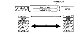
ここで、無線基地局DeNB1と無線基地局DeNB2とが、X2-Cインターフェイスを介して接続されており、無線基地局DeNB2と無線基地局eNB1とが、X2-Cインターフェイスを介して接続されている。 Here, the radio base station DeNB1 and the radio base station DeNB2 are connected via the X2-C interface, and the radio base station DeNB2 and the radio base station eNB1 are connected via the X2-C interface. .
また、無線基地局DeNB1、無線基地局DeNB2及び無線基地局eNB1のそれぞれと、交換局MMEとが、S1-MMEインターフェイスを介して接続されている。 In addition, each of the radio base station DeNB1, the radio base station DeNB2, and the radio base station eNB1 is connected to the exchange MME via an S1-MME interface.
かかる移動通信システムにおいて、移動局UEは、無線基地局eNB(DeNB)及びリレーノードRNとの間で無線ベアラを設定して、無線通信を行うように構成されている。 In such a mobile communication system, the mobile station UE is configured to perform radio communication by setting a radio bearer between the radio base station eNB (DeNB) and the relay node RN.
また、かかる移動通信システムでは、図1の(1)に示すように、移動局UEが、リレーノードRN2との間で無線ベアラを設定しリレーノードRN2及び無線基地局DeNB2を介して通信を行っている状態と、無線基地局DeNB2との間で無線ベアラを設定し無線基地局DeNB2を介して通信を行っている状態との間で、ハンドオーバ処理を行うように構成されている。 Further, in such a mobile communication system, as shown in FIG. 1 (1), the mobile station UE sets up a radio bearer with the relay node RN2, and performs communication via the relay node RN2 and the radio base station DeNB2. And a state in which a radio bearer is set up with the radio base station DeNB2 and a communication is performed via the radio base station DeNB2.
また、かかるハンドオーバ処理において、リレーノードRN2と無線基地局DeNB2との間のX2-C無線ベアラ(無線ベアラ)を介して、ハンドオーバ処理に係る制御信号(X2AP信号)を送受信するように構成されている。 Further, in the handover process, the control signal (X2AP signal) related to the handover process is configured to be transmitted and received via the X2-C radio bearer (radio bearer) between the relay node RN2 and the radio base station DeNB2. Yes.
例えば、図2乃至図4に示すように、リレーノードRN2及び無線基地局DeNB2は、X2-C無線ベアラを設定するためのX2-C無線ベアラ機能として、物理(PHY)レイヤ機能と、物理(PHY)レイヤ機能の上位レイヤ機能として設けられているMAC(Media Access Control)レイヤ機能と、MACレイヤ機能の上位レイヤ機能として設けられているRLC(Radio Link Control)レイヤ機能と、RLCレイヤ機能の上位レイヤ機能として設けられているPDCP(Packet Data Convergence Protocol)レイヤ機能とを具備している。 For example, as illustrated in FIG. 2 to FIG. 4, the relay node RN2 and the radio base station DeNB2 have a physical (PHY) layer function and a physical (PHY) function as an X2-C radio bearer function for setting an X2-C radio bearer. (PHY) layer function MAC (Media Access Control) layer function provided as an upper layer function, RLC (Radio Link Control) layer function provided as an MAC layer function upper layer function, and RLC layer function upper layer function PDCP (Packet Data Convergence Protocol) layer function provided as a layer function.
なお、リレーノードRN2及び無線基地局DeNB2は、PDCPレイヤ機能の上位レイヤ機能として設けられているRRC(Radio Resource Control)レイヤ機能を具備してもよい。 Note that the relay node RN2 and the radio base station DeNB2 may include an RRC (Radio Resource Control) layer function provided as an upper layer function of the PDCP layer function.
また、図2に示すように、リレーノードRN2及び無線基地局DeNB2は、X2-C無線ベアラ機能の上位レイヤ機能として、リレーノードRN2と無線基地局DeNB2との間のセキュリティ処理を行うように構成されているIPレイヤ機能(第1レイヤ機能)を具備し、IPレイヤ機能の上位レイヤ機能として、X2-C無線ベアラに対するキープアライブ処理を行うように構成されているSCTPレイヤ機能(第2レイヤ機能)とを具備してもよい。 Further, as shown in FIG. 2, the relay node RN2 and the radio base station DeNB2 are configured to perform security processing between the relay node RN2 and the radio base station DeNB2 as an upper layer function of the X2-C radio bearer function. SCTP layer function (second layer function) configured to perform keep-alive processing for the X2-C radio bearer as an upper layer function of the IP layer function. ).
或いは、図3に示すように、リレーノードRN2及び無線基地局DeNB2は、X2-C無線ベアラ機能の上位レイヤ機能として、X2-C無線ベアラに対するキープアライブ処理を行うように構成されているSCTPレイヤ機能を具備してもよい。図3の例では、リレーノードRN2及び無線基地局DeNB2は、リレーノードRN2と無線基地局DeNB2との間のセキュリティ処理を行うように構成されているIPレイヤ機能を具備していない。 Or, as shown in FIG. 3, the relay node RN2 and the radio base station DeNB2 are configured to perform a keep-alive process for the X2-C radio bearer as an upper layer function of the X2-C radio bearer function. A function may be provided. In the example of FIG. 3, the relay node RN2 and the radio base station DeNB2 do not have an IP layer function configured to perform security processing between the relay node RN2 and the radio base station DeNB2.
さらに、図4に示すように、リレーノードRN2及び無線基地局DeNB2は、X2-C無線ベアラ機能の上位レイヤ機能として、X2-C無線ベアラに対するキープアライブ処理を行うように構成されているSCTPレイヤ機能、及び、リレーノードRN2と無線基地局DeNB2との間のセキュリティ処理を行うように構成されているIPレイヤ機能を具備しなくてもよい。 Furthermore, as shown in FIG. 4, the relay node RN2 and the radio base station DeNB2 are configured to perform a keep-alive process for the X2-C radio bearer as an upper layer function of the X2-C radio bearer function. The function and the IP layer function configured to perform the security process between the relay node RN2 and the radio base station DeNB2 may not be provided.
以下、図5を参照して、本実施形態に係る移動通信システムにおいて、移動局UEが、リレーノードRN2との間で無線ベアラを設定しリレーノードRN2及び無線基地局DeNB2を介して通信を行っている状態から、無線基地局DeNB2との間で無線ベアラを設定し無線基地局DeNB2を介して通信を行っている状態に、ハンドオーバする動作について説明する。 Hereinafter, with reference to FIG. 5, in the mobile communication system according to the present embodiment, the mobile station UE sets up a radio bearer with the relay node RN2, and performs communication via the relay node RN2 and the radio base station DeNB2. A description will be given of an operation for performing a handover from a state in which communication is performed to a state in which a radio bearer is set with the radio base station DeNB2 and communication is performed via the radio base station DeNB2.
図5に示すように、リレーノードRN2が、ステップS1000において、移動局UEの「UE Context」を管理しており、ステップS1001において、無線基地局DeNB2に対して、X2-C無線ベアラを介して、移動局UEのリレーノードRN2から無線基地局DeNB2へのハンドオーバを要求する「HO Request(ハンドオーバ要求信号)」を送信する。 As shown in FIG. 5, the relay node RN2 manages the “UE Context” of the mobile station UE in step S1000. In step S1001, the relay node RN2 manages the radio base station DeNB2 via the X2-C radio bearer. The mobile station UE transmits a “HO Request (handover request signal)” requesting handover from the relay node RN2 of the mobile station UE to the radio base station DeNB2.
無線基地局DeNB2は、「HO Request」を受信すると、ステップS1002において、移動局UEの「UE Context」を記憶し、ステップS1003において、リレーノードRN2に対して、X2-C無線ベアラを介して、「HO Request Ack(ハンドオーバ要求確認信号)」を送信する。 When receiving the “HO Request”, the radio base station DeNB2 stores “UE Context” of the mobile station UE in Step S1002, and in Step S1003, to the relay node RN2 via the X2-C radio bearer, “HO Request Ack (handover request confirmation signal)” is transmitted.
ステップS1004において、リレーノードRN2は、移動局UEに対して、RRCレイヤ機能によって、無線基地局DeNB2にハンドオーバするように指示する「HO Command(ハンドオーバ指示信号)」を送信する。 In step S1004, the relay node RN2 transmits “HO Command (handover instruction signal)” instructing the mobile station UE to perform handover to the radio base station DeNB2 by the RRC layer function.
ステップS1005において、移動局UEは、RRCレイヤ機能によって、無線基地局DeNB2に対して、「HO Complete(ハンドオーバ完了信号)」を送信する。 In step S1005, the mobile station UE transmits “HO Complete (handover completion signal)” to the radio base station DeNB2 by the RRC layer function.
ステップS1006において、無線基地局DeNB2は、S1-MMEインターフェイスを介して、交換局MMEに対して、「Path Swith Request(パス切替要求信号)」を送信する。 In step S1006, the radio base station DeNB2 transmits a “Path Switch Request (path switching request signal)” to the switching center MME via the S1-MME interface.
ステップS1007において、交換局MMEは、S1-MMEインターフェイスを介して、無線基地局DeNB2に対して、「Path Swith Request Ack(パス切替要求確認信号)」を送信すると共に、移動局UE宛ての信号の転送先を、リレーノードRN2から無線基地局DeNB2に切り替える。 In step S1007, the switching center MME transmits a “Path Switch Request Ack (path switching request confirmation signal)” to the radio base station DeNB2 via the S1-MME interface, and transmits a signal addressed to the mobile station UE. The transfer destination is switched from the relay node RN2 to the radio base station DeNB2.
ステップS1008において、無線基地局DeNB2は、X2-C無線ベアラを介して、リレーノードRN2に対して、「UE Context Release」を送信し、リレーノードRN2は、「UE Context Release」に応じて、移動局UEの「UE Context」の管理を終了する。 In step S1008, the radio base station DeNB2 transmits “UE Context Release” to the relay node RN2 via the X2-C radio bearer, and the relay node RN2 moves according to the “UE Context Release”. Management of the “UE Context” of the station UE is terminated.
なお、図5において、リレーノードRN2と無線基地局DeNB2とが入れ替わってもよい。 In FIG. 5, the relay node RN2 and the radio base station DeNB2 may be interchanged.
本実施形態に係る移動通信システムによれば、LTE方式の移動通信システムで用いられていた各装置のプロトコルスタックに対して、大きな改修を施すことなく、リレーノードRNが関連するハンドオーバ処理を実現することができる。 According to the mobile communication system according to the present embodiment, the handover process related to the relay node RN is realized without significantly modifying the protocol stack of each device used in the LTE mobile communication system. be able to.
また、本実施形態に係る移動通信システムによれば、移動局UEのハンドオーバ処理の際に、無線基地局DeNB2とリレーノードRN2との間で、X2-C無線ベアラを設定する必要がないため、ハンドオーバ処理を迅速に行うことができる。 Further, according to the mobile communication system according to the present embodiment, it is not necessary to set up an X2-C radio bearer between the radio base station DeNB2 and the relay node RN2 during the handover process of the mobile station UE. The handover process can be performed quickly.
なお、上述の移動局UEやリレーノードRNや無線基地局eNBや交換局MMEの動作は、ハードウェアによって実施されてもよいし、プロセッサによって実行されるソフトウェアモジュールによって実施されてもよいし、両者の組み合わせによって実施されてもよい。 Note that the operations of the mobile station UE, the relay node RN, the radio base station eNB, and the switching center MME described above may be performed by hardware, may be performed by a software module executed by a processor, or both. It may be implemented by a combination of
ソフトウェアモジュールは、RAM(Random Access Memory)や、フラッシュメモリや、ROM(Read Only Memory)や、EPROM(Erasable Programmable ROM)や、EEPROM(Electronically Erasable and Programmable ROM)や、レジスタや、ハードディスクや、リムーバブルディスクや、CD-ROMといった任意形式の記憶媒体内に設けられていてもよい。 The software module includes a RAM (Random Access Memory), a flash memory, a ROM (Read Only Memory), an EPROM (Erasable Programmable ROM), an EEPROM (Electronically Erasable and Programmable ROM, a Hard Disk, a Registered ROM, a Hard Disk Alternatively, it may be provided in a storage medium of an arbitrary format such as a CD-ROM.
かかる記憶媒体は、プロセッサが当該記憶媒体に情報を読み書きできるように、当該プロセッサに接続されている。また、かかる記憶媒体は、プロセッサに集積されていてもよい。また、かかる記憶媒体及びプロセッサは、ASIC内に設けられていてもよい。かかるASICは、移動局UEやリレーノードRNや無線基地局eNBや交換局MME内に設けられていてもよい。また、かかる記憶媒体及びプロセッサは、ディスクリートコンポーネントとして移動局UEやリレーノードRNや無線基地局eNBや交換局MME内に設けられていてもよい。 Such a storage medium is connected to the processor so that the processor can read and write information from and to the storage medium. Further, such a storage medium may be integrated in the processor. Such a storage medium and processor may be provided in the ASIC. Such an ASIC may be provided in the mobile station UE, the relay node RN, the radio base station eNB, or the exchange MME. Further, the storage medium and the processor may be provided as a discrete component in the mobile station UE, the relay node RN, the radio base station eNB, or the exchange MME.
以上、上述の実施形態を用いて本発明について詳細に説明したが、当業者にとっては、本発明が本明細書中に説明した実施形態に限定されるものではないということは明らかである。本発明は、特許請求の範囲の記載により定まる本発明の趣旨及び範囲を逸脱することなく修正及び変更態様として実施することができる。従って、本明細書の記載は、例示説明を目的とするものであり、本発明に対して何ら制限的な意味を有するものではない。 Although the present invention has been described in detail using the above-described embodiments, it is obvious to those skilled in the art that the present invention is not limited to the embodiments described in this specification. The present invention can be implemented as modified and changed modes without departing from the spirit and scope of the present invention defined by the description of the scope of claims. Therefore, the description of the present specification is for illustrative purposes and does not have any limiting meaning to the present invention.
UE…移動局
RN…リレーノード
eNB…無線基地局
MME…交換局
UE ... mobile station RN ... relay node eNB ... radio base station MME ... switching station
Claims (1)
前記リレーノードが、前記第1無線ベアラを介して、前記無線基地局に対して、X2APレイヤのハンドオーバ要求信号を送信する工程と、
前記無線基地局が、前記X2APレイヤのハンドオーバ要求信号を受信すると、前記第1無線ベアラを介して、前記リレーノードに対して、X2APレイヤのハンドオーバ要求確認信号を送信する工程と、
前記リレーノードが、前記X2APレイヤのハンドオーバ要求確認信号を受信すると、前記第2無線ベアラを介して、前記移動局に対して、前記無線基地局にハンドオーバするように指示するRRCレイヤのハンドオーバ指示信号を送信する工程とを有することを特徴とするハンドオーバ方法。 When the relay node and the radio base station are connected via the first radio bearer, the mobile station sets up a second radio bearer with the relay node, and passes the relay node and the radio base station. A handover method for switching from a state of performing communication to a state of setting a third radio bearer with the radio base station and performing communication via the radio base station,
The relay node transmitting an X2AP layer handover request signal to the radio base station via the first radio bearer;
When the radio base station receives the X2AP layer handover request signal, the radio base station transmits an X2AP layer handover request confirmation signal to the relay node via the first radio bearer;
When the relay node receives the X2AP layer handover request confirmation signal, the RRC layer handover instruction signal instructs the mobile station to perform handover to the radio base station via the second radio bearer. A handover method characterized by comprising:
Priority Applications (11)
| Application Number | Priority Date | Filing Date | Title |
|---|---|---|---|
| JP2009108558A JP5072900B2 (en) | 2009-04-27 | 2009-04-27 | Handover method |
| KR1020117026173A KR101324298B1 (en) | 2009-04-27 | 2010-04-21 | Mobile communication system |
| RU2011144424/07A RU2498532C2 (en) | 2009-04-27 | 2010-04-21 | Mobile communication system |
| EP10769653.6A EP2426990B1 (en) | 2009-04-27 | 2010-04-21 | Mobile communication system |
| CN201080018580.7A CN102415141B (en) | 2009-04-27 | 2010-04-21 | Mobile communication system |
| HUE13193055A HUE032067T2 (en) | 2009-04-27 | 2010-04-21 | Mobile communication system |
| PCT/JP2010/057082 WO2010125954A1 (en) | 2009-04-27 | 2010-04-21 | Mobile communication system |
| CA2759905A CA2759905C (en) | 2009-04-27 | 2010-04-21 | Mobile communication system |
| MX2011011308A MX2011011308A (en) | 2009-04-27 | 2010-04-21 | Mobile communication system. |
| EP13193055.4A EP2699038B1 (en) | 2009-04-27 | 2010-04-21 | Mobile communication system |
| US13/266,299 US8830901B2 (en) | 2009-04-27 | 2010-04-21 | Mobile communication system |
Applications Claiming Priority (1)
| Application Number | Priority Date | Filing Date | Title |
|---|---|---|---|
| JP2009108558A JP5072900B2 (en) | 2009-04-27 | 2009-04-27 | Handover method |
Related Child Applications (1)
| Application Number | Title | Priority Date | Filing Date |
|---|---|---|---|
| JP2011270331A Division JP5373044B2 (en) | 2011-12-09 | 2011-12-09 | Mobile communication system |
Publications (3)
| Publication Number | Publication Date |
|---|---|
| JP2010258919A JP2010258919A (en) | 2010-11-11 |
| JP2010258919A5 JP2010258919A5 (en) | 2011-10-27 |
| JP5072900B2 true JP5072900B2 (en) | 2012-11-14 |
Family
ID=43032108
Family Applications (1)
| Application Number | Title | Priority Date | Filing Date |
|---|---|---|---|
| JP2009108558A Active JP5072900B2 (en) | 2009-04-27 | 2009-04-27 | Handover method |
Country Status (9)
| Country | Link |
|---|---|
| US (1) | US8830901B2 (en) |
| EP (2) | EP2699038B1 (en) |
| JP (1) | JP5072900B2 (en) |
| KR (1) | KR101324298B1 (en) |
| CN (1) | CN102415141B (en) |
| HU (1) | HUE032067T2 (en) |
| MX (1) | MX2011011308A (en) |
| RU (1) | RU2498532C2 (en) |
| WO (1) | WO2010125954A1 (en) |
Families Citing this family (5)
| Publication number | Priority date | Publication date | Assignee | Title |
|---|---|---|---|---|
| CA2760047A1 (en) * | 2009-04-27 | 2010-11-04 | Ntt Docomo, Inc. | Mobile communication system |
| WO2013070247A1 (en) * | 2011-11-11 | 2013-05-16 | Research In Motion Limited | Method and apparatus for managing mobility of a plurality of relay nodes |
| WO2013070246A1 (en) | 2011-11-11 | 2013-05-16 | Research In Motion Limited | Method an relay node for initiating a direct attachment to a target network node |
| KR102265454B1 (en) * | 2014-04-11 | 2021-06-15 | 삼성전자 주식회사 | Apparatus and method for improving communication quality in mobile communication network |
| US10028186B1 (en) * | 2017-03-24 | 2018-07-17 | Sprint Communications Company L.P. | Wireless communication system to redirect use equipment (UE) from a wireless relay to a donor base station |
Family Cites Families (14)
| Publication number | Priority date | Publication date | Assignee | Title |
|---|---|---|---|---|
| RU2387075C2 (en) * | 2003-09-03 | 2010-04-20 | Бехзад МОХЕББИ | Additional honeycomb amplifier with small operating range |
| CN101009926A (en) | 2005-10-17 | 2007-08-01 | 三星电子株式会社 | Apparatus and method for supporting handover in a wireless access communication system |
| KR100871620B1 (en) | 2005-11-10 | 2008-12-02 | 삼성전자주식회사 | Apparatus and method for handover for multihop system in broadband wireless access communication network |
| WO2007053950A1 (en) * | 2005-11-12 | 2007-05-18 | Nortel Networks Limited | Media access control data plane system and method for wireless communication networks |
| CN101064911B (en) * | 2006-04-28 | 2012-08-22 | 上海贝尔阿尔卡特股份有限公司 | Switch control method, relay station and base station for wireless access system |
| US7620370B2 (en) * | 2006-07-13 | 2009-11-17 | Designart Networks Ltd | Mobile broadband wireless access point network with wireless backhaul |
| KR100908244B1 (en) | 2007-01-08 | 2009-07-20 | 한국전자통신연구원 | Handover Method and Multi-hop Relay System Using Repeater with Handover Control Function |
| JP2009060156A (en) * | 2007-08-03 | 2009-03-19 | Ntt Docomo Inc | Communication method, and radio base station |
| EP2184935A4 (en) * | 2007-08-10 | 2013-08-14 | Mitsubishi Electric Corp | Radio communication system and base station |
| FI20075697A0 (en) | 2007-10-02 | 2007-10-02 | Nokia Siemens Networks Oy | Method, computer program, apparatus and system |
| JP4988644B2 (en) * | 2008-04-24 | 2012-08-01 | 京セラ株式会社 | Relay station, radio communication system, and radio communication method |
| WO2010059100A1 (en) * | 2008-11-21 | 2010-05-27 | Telefonaktiebolaget L M Ericsson (Publ) | Gateway configured to provide a handover, converting and routing function |
| US8305965B2 (en) * | 2009-01-06 | 2012-11-06 | Texas Instruments Incorporated | Protocol stack and scheduler for L3 relay |
| JPWO2010116621A1 (en) | 2009-03-30 | 2012-10-18 | パナソニック株式会社 | Wireless communication device |
-
2009
- 2009-04-27 JP JP2009108558A patent/JP5072900B2/en active Active
-
2010
- 2010-04-21 MX MX2011011308A patent/MX2011011308A/en active IP Right Grant
- 2010-04-21 HU HUE13193055A patent/HUE032067T2/en unknown
- 2010-04-21 KR KR1020117026173A patent/KR101324298B1/en active IP Right Grant
- 2010-04-21 US US13/266,299 patent/US8830901B2/en active Active
- 2010-04-21 EP EP13193055.4A patent/EP2699038B1/en active Active
- 2010-04-21 EP EP10769653.6A patent/EP2426990B1/en active Active
- 2010-04-21 CN CN201080018580.7A patent/CN102415141B/en active Active
- 2010-04-21 RU RU2011144424/07A patent/RU2498532C2/en active
- 2010-04-21 WO PCT/JP2010/057082 patent/WO2010125954A1/en active Application Filing
Also Published As
| Publication number | Publication date |
|---|---|
| MX2011011308A (en) | 2011-12-06 |
| HUE032067T2 (en) | 2017-08-28 |
| EP2699038A1 (en) | 2014-02-19 |
| RU2498532C2 (en) | 2013-11-10 |
| US20120044859A1 (en) | 2012-02-23 |
| CN102415141B (en) | 2014-06-25 |
| EP2699038B1 (en) | 2016-10-12 |
| CN102415141A (en) | 2012-04-11 |
| EP2426990A4 (en) | 2013-05-29 |
| KR20120016226A (en) | 2012-02-23 |
| KR101324298B1 (en) | 2013-10-30 |
| EP2426990A1 (en) | 2012-03-07 |
| WO2010125954A1 (en) | 2010-11-04 |
| JP2010258919A (en) | 2010-11-11 |
| US8830901B2 (en) | 2014-09-09 |
| EP2426990B1 (en) | 2015-01-21 |
| RU2011144424A (en) | 2013-06-10 |
Similar Documents
| Publication | Publication Date | Title |
|---|---|---|
| US8761123B2 (en) | Mobile communication system | |
| JP4954238B2 (en) | Mobile communication system | |
| JP5225191B2 (en) | Mobile communication system | |
| US8498236B2 (en) | Mobile communication system | |
| JP5072900B2 (en) | Handover method | |
| WO2010126052A1 (en) | Mobile communication system | |
| JP5247881B2 (en) | Mobile communication system | |
| JP5373044B2 (en) | Mobile communication system | |
| JP5058380B2 (en) | Mobile communication system | |
| JP5564092B2 (en) | Mobile communication system | |
| CA2759905C (en) | Mobile communication system | |
| JP2011120179A (en) | Mobile communication system and radio base station |
Legal Events
| Date | Code | Title | Description |
|---|---|---|---|
| A621 | Written request for application examination |
Free format text: JAPANESE INTERMEDIATE CODE: A621 Effective date: 20110331 |
|
| A521 | Request for written amendment filed |
Free format text: JAPANESE INTERMEDIATE CODE: A523 Effective date: 20110913 |
|
| A871 | Explanation of circumstances concerning accelerated examination |
Free format text: JAPANESE INTERMEDIATE CODE: A871 Effective date: 20110913 |
|
| A521 | Request for written amendment filed |
Free format text: JAPANESE INTERMEDIATE CODE: A523 Effective date: 20110914 |
|
| A975 | Report on accelerated examination |
Free format text: JAPANESE INTERMEDIATE CODE: A971005 Effective date: 20111003 |
|
| A131 | Notification of reasons for refusal |
Free format text: JAPANESE INTERMEDIATE CODE: A131 Effective date: 20111011 |
|
| A521 | Request for written amendment filed |
Free format text: JAPANESE INTERMEDIATE CODE: A523 Effective date: 20111209 |
|
| A131 | Notification of reasons for refusal |
Free format text: JAPANESE INTERMEDIATE CODE: A131 Effective date: 20120306 |
|
| A521 | Request for written amendment filed |
Free format text: JAPANESE INTERMEDIATE CODE: A523 Effective date: 20120502 |
|
| TRDD | Decision of grant or rejection written | ||
| A01 | Written decision to grant a patent or to grant a registration (utility model) |
Free format text: JAPANESE INTERMEDIATE CODE: A01 Effective date: 20120724 |
|
| A01 | Written decision to grant a patent or to grant a registration (utility model) |
Free format text: JAPANESE INTERMEDIATE CODE: A01 |
|
| A61 | First payment of annual fees (during grant procedure) |
Free format text: JAPANESE INTERMEDIATE CODE: A61 Effective date: 20120821 |
|
| R150 | Certificate of patent or registration of utility model |
Ref document number: 5072900 Country of ref document: JP Free format text: JAPANESE INTERMEDIATE CODE: R150 Free format text: JAPANESE INTERMEDIATE CODE: R150 |
|
| FPAY | Renewal fee payment (event date is renewal date of database) |
Free format text: PAYMENT UNTIL: 20150831 Year of fee payment: 3 |
|
| R250 | Receipt of annual fees |
Free format text: JAPANESE INTERMEDIATE CODE: R250 |
|
| R250 | Receipt of annual fees |
Free format text: JAPANESE INTERMEDIATE CODE: R250 |
|
| R250 | Receipt of annual fees |
Free format text: JAPANESE INTERMEDIATE CODE: R250 |
|
| R250 | Receipt of annual fees |
Free format text: JAPANESE INTERMEDIATE CODE: R250 |
|
| R250 | Receipt of annual fees |
Free format text: JAPANESE INTERMEDIATE CODE: R250 |
|
| R250 | Receipt of annual fees |
Free format text: JAPANESE INTERMEDIATE CODE: R250 |
|
| R250 | Receipt of annual fees |
Free format text: JAPANESE INTERMEDIATE CODE: R250 |
|
| R250 | Receipt of annual fees |
Free format text: JAPANESE INTERMEDIATE CODE: R250 |
|
| R250 | Receipt of annual fees |
Free format text: JAPANESE INTERMEDIATE CODE: R250 |
|
| R250 | Receipt of annual fees |
Free format text: JAPANESE INTERMEDIATE CODE: R250 |