JP4936799B2 - Electronic camera - Google Patents
Electronic camera Download PDFInfo
- Publication number
- JP4936799B2 JP4936799B2 JP2006164118A JP2006164118A JP4936799B2 JP 4936799 B2 JP4936799 B2 JP 4936799B2 JP 2006164118 A JP2006164118 A JP 2006164118A JP 2006164118 A JP2006164118 A JP 2006164118A JP 4936799 B2 JP4936799 B2 JP 4936799B2
- Authority
- JP
- Japan
- Prior art keywords
- setting
- focus
- degree
- lens
- imaging surface
- Prior art date
- Legal status (The legal status is an assumption and is not a legal conclusion. Google has not performed a legal analysis and makes no representation as to the accuracy of the status listed.)
- Expired - Fee Related
Links
Images


Landscapes
- Focusing (AREA)
- Automatic Focus Adjustment (AREA)
- Studio Devices (AREA)
Description
この発明は、電子カメラに関し、特にたとえば、撮像面に照射された被写界の光学像に対応する画像信号に基づいて光学レンズから撮像面までの距離を調整する、電子カメラに関する。 The present invention relates to an electronic camera, and more particularly to an electronic camera that adjusts a distance from an optical lens to an imaging surface based on an image signal corresponding to an optical image of an object scene irradiated on the imaging surface.
従来のこの種の装置の一例が、特許文献1に開示されている。この従来技術によれば、フォーカスレンズの位置は、粗調整の後に微調整される。また、微調整時の補正量が基準値を超えると、粗調整動作が再開される。ここで、基準値は、広角側で大きい値を示す一方、望遠側で小さい値を示す。これによって、ズーム位置の変化に関らず、迅速かつ安定的なフォーカス動作が実現される。
しかし、従来技術では、手振れに起因するフォーカス精度の低下を如何に解決するかについて何ら開示していない。 However, the prior art does not disclose how to solve the decrease in focus accuracy caused by camera shake.
それゆえに、この発明の主たる目的は、手振れに関らずフォーカスを的確に調整することができる、電子カメラを提供することである。 Therefore, a main object of the present invention is to provide an electronic camera capable of accurately adjusting the focus regardless of camera shake.
請求項1の発明に従う電子カメラ(10:実施例で相当する参照符号。以下同じ)は、レンズ(12)を経た被写界像を捉える撮像面を有する撮像手段(14)、レンズから撮像面までの距離を設定幅ずつ変更する変更手段(16)、撮像面で捉えられた被写界像の合焦度を変更手段の変更処理と並行して検出する検出手段(26, S29)、第1変更幅を変更手段に設定する第1設定手段(S1)、第1変更幅よりも短い第2変更幅を変更手段に設定する第2設定手段(S5)、第2設定手段の設定に対応して検出手段によって検出された合焦度の信頼性を示すパラメータ値を第1設定手段の設定に対応して検出手段によって検出された合焦度の大きさに対する第2設定手段の設定に対応して検出手段によって検出された合焦度の大きさの割合として算出する算出手段(S9, S31, S33)、算出手段によって算出されたパラメータ値が既定値範囲に属するとき検出手段によって検出された合焦度に基づいてレンズから撮像面までの適正距離を決定する決定手段(S17, S19)、および算出手段によって算出されたパラメータ値が既定数値範囲から下側に外れるとき検出手段を第2設定手段の設定に対応した状態でのみ再起動する第1再起動手段(S11)を備える。 An electronic camera according to the invention of claim 1 (10: reference numeral corresponding to the embodiment; the same applies hereinafter) includes an image pickup means (14) having an image pickup surface for capturing an object scene image that has passed through the lens (12); Change means (16) for changing the distance up to the set width, detection means (26, S29) for detecting the degree of focus of the object scene image captured on the imaging surface in parallel with the change process of the change means, Corresponds to the setting of the first setting means (S1) for setting the change width as the change means, the second setting means (S5) for setting the second change width shorter than the first change width as the change means, and the setting of the second setting means The parameter value indicating the reliability of the focus degree detected by the detection means corresponds to the setting of the second setting means for the magnitude of the focus degree detected by the detection means corresponding to the setting of the first setting means. calculating means for calculating a ratio of the size of the detected degree of focus by the detecting means and (S9, S31, S33), calculates Determination means (S17, S19) for determining an appropriate distance from the lens to the imaging surface based on the degree of focus detected by the detection means when the parameter value calculated by the stage belongs to the predetermined value range, and calculation by the calculation means parameter values comprises a first restart means (S11) to restart only when the corresponding detection means when the outside on the lower side of the setting of second setting means from the default value range.
撮像手段は、レンズを経た被写界像を捉える撮像面を有する。レンズから撮像面までの距離は、変更手段によって設定幅ずつ変更される。撮像面で捉えられた被写界像の合焦度は、変更手段の変更処理と並行して検出手段によって検出される。第1設定手段は第1変更幅を変更手段に設定し、第2設定手段は第1変更幅よりも短い第2変更幅を変更手段に設定する。 The imaging means has an imaging surface for capturing an object scene image that has passed through the lens. The distance from the lens to the imaging surface is changed by the set width by the changing means. The degree of focus of the object scene image captured on the imaging surface is detected by the detecting unit in parallel with the changing process of the changing unit. The first setting means sets the first change width to the change means, and the second setting means sets the second change width shorter than the first change width to the change means.
算出手段は、第2設定手段の設定に対応して検出手段によって検出された合焦度の信頼性を示すパラメータ値を、第1設定手段の設定に対応して検出手段によって検出された合焦度の大きさに対する第2設定手段の設定に対応して検出手段によって検出された合焦度の大きさの割合として算出する。決定手段は、算出手段によって算出されたパラメータ値が既定値範囲に属するとき、検出手段によって検出された合焦度に基づいてレンズから撮像面までの適正距離を決定する。第1再起動手段は、算出手段によって算出されたパラメータ値が既定数値範囲から下側に外れるとき、検出手段を第2設定手段の設定に対応した状態でのみ再起動する。 The calculation means calculates the parameter value indicating the reliability of the degree of focus detected by the detection means corresponding to the setting of the second setting means, and the focus detected by the detection means corresponding to the setting of the first setting means. It is calculated as a ratio of the magnitude of the degree of focus detected by the detection means corresponding to the setting of the second setting means relative to the magnitude of the degree . The determining unit determines an appropriate distance from the lens to the imaging surface based on the degree of focus detected by the detecting unit when the parameter value calculated by the calculating unit belongs to the predetermined value range. The first restarting means restarts the detecting means only in a state corresponding to the setting of the second setting means when the parameter value calculated by the calculating means falls outside the predetermined numerical value range.
手振れが発生すると、撮像面で捉えられる被写界像の空間周波数が低下する。したがって、手振れがある状態で検出される合焦度の信頼性は、手振れがない状態で検出される合焦度の信頼性よりも小さくなる。また、第2変更幅に従う変更処理に要する時間は、第1変更幅に従う変更処理に要するよりも長い。したがって、第2変更幅に従う変更処理の途中で手振れが発生する確率は、第1変更幅に従う変更処理の途中で手振れが発生する確率よりも高くなる。 When camera shake occurs, the spatial frequency of the object scene image captured on the imaging surface decreases. Therefore, the reliability of the degree of focus detected in the state where there is camera shake is smaller than the reliability of the degree of focus detected in the state where there is no camera shake. Further, the time required for the change process according to the second change width is longer than that required for the change process according to the first change width. Therefore, the probability that camera shake occurs during the change process according to the second change width is higher than the probability that camera shake occurs during the change process according to the first change width.
このような性質を考慮して、請求項1の発明では、パラメータ値が既定値範囲から下側に外れたとき(第2設定手段の設定に対応して検出された合焦度の信頼性が低下したとき)、第2変更幅に従う変更処理の途中で手振れが発生したとみなし、検出手段を第2設定手段の設定に対応した状態でのみ再起動するようにしている。再起動によって検出された合焦度の信頼性が高く、パラメータ値が既定値範囲に属することとなったときは、検出手段によって検出された合焦度に基づいてレンズから撮像面までの適正距離が決定される。これによって、手振れに関らずフォーカスを的確に調整することができる。
Such properties into consideration, in the invention of
請求項2の発明に従う電子カメラは、請求項1に従属し、決定手段は、パラメータ値が既定値範囲内の下側に分布する第1値範囲に属するとき第1設定手段の設定に対応して検出手段によって検出された合焦度に基づいて適正距離を決定する第1距離決定手段(S17)を含む。パラメータ値が第1数値範囲に属するときは、第1設定手段の設定に対応して検出された合焦度の方がより信頼できるとみなされ、この合焦度に対応する距離が合焦点として決定される。
Electronic camera according to the present invention of claim 2 depends on
請求項3の発明に従う電子カメラは、請求項1または2に従属し、決定手段は、パラメータ値が既定値範囲内の上側に分布する第2値範囲に属するとき第2設定手段の設定に対応して検出手段によって検出された合焦度に基づいて適正距離を決定する第2距離決定手段(S19)を含む。パラメータ値が第2値範囲に属するときは、第2設定手段の設定に対応して検出された合焦度の方がより信頼できるとみなされ、この合焦度に対応する距離が合焦点として決定される。
Electronic camera according to the present invention of
請求項4の発明に従う電子カメラは、請求項1ないし3のいずれかに従属し、算出手段によって算出されたパラメータ値が既定値範囲から上側に外れるとき検出手段を第1設定手段の設定に対応した状態で再起動した後に第2設定手段の設定に対応した状態で再起動する第2再起動手段(S15)をさらに備える。パラメータ値が大きいときは、第1設定手段によって検出された合焦度および第2設定手段によって設定された合焦度のいずれも信頼できないとみなされ、前記検出手段は第1設定手段の設定に対応した状態で再起動された後に第2設定手段の設定に対応した状態で再起動される。 An electronic camera according to a fourth aspect of the invention is dependent on any one of the first to third aspects , and the detection means corresponds to the setting of the first setting means when the parameter value calculated by the calculation means deviates from the predetermined value range. And a second restarting means (S15) for restarting in a state corresponding to the setting of the second setting means after restarting in this state. When the parameter value is large, it is considered that neither the in-focus degree detected by the first setting means nor the in-focus degree set by the second setting means is reliable, and the detection means sets the first setting means. After restarting in a corresponding state, restarting is performed in a state corresponding to the setting of the second setting means.
請求項5の発明に従う電子カメラは、請求項1ないし4のいずれかに従属し、距離調整操作を受け付ける受付手段(46)をさらに備え、第1設定手段は第2設定手段の設定処理に先立って設定処理を実行する。 An electronic camera according to a fifth aspect of the present invention is dependent on any one of the first to fourth aspects, further comprising a receiving means (46) for receiving a distance adjustment operation, wherein the first setting means is prior to the setting process of the second setting means. To execute the setting process.
請求項6の発明に従う距離制御プログラムは、レンズ(12)を経た被写界像を捉える撮像面を有する撮像手段(14)、レンズから撮像面までの距離を設定幅ずつ変更する変更手段(16)、撮像面で捉えられた被写界像の合焦度を変更手段の変更処理と並行して検出する検出手段(26)を備える電子カメラ(10)のプロセサ(44)に、第1変更幅を変更手段に設定する第1設定ステップ(S1)、第1変更幅よりも短い第2変更幅を変更手段に設定する第2設定ステップ(S5)、第2設定ステップの設定に対応して検出手段によって検出された合焦度の信頼性を示すパラメータ値を第1設定ステップの設定に対応して検出手段によって検出された合焦度の大きさに対する第2設定ステップの設定に対応して検出手段によって検出された合焦度の大きさの割合として算出する算出ステップ(S9, S31, S33)、算出ステップによって算出されたパラメータ値が既定値範囲に属するとき検出手段によって検出された合焦度に基づいてレンズから撮像面までの適正距離を決定する決定ステップ(S17, S19)、および算出ステップによって算出されたパラメータ値が既定値範囲から下側に外れるとき検出手段を第2設定ステップの設定に対応した状態でのみ再起動する再起動ステップ(S11)を実行させるための、距離制御プログラムである。 The distance control program according to the invention of claim 6 includes an image pickup means (14) having an image pickup surface for capturing an object scene image passing through the lens (12), and a change means (16) for changing the distance from the lens to the image pickup surface by a set width. ), The first change to the processor (44) of the electronic camera (10) provided with the detection means (26) for detecting the focus degree of the object scene image captured on the imaging surface in parallel with the change process of the change means Corresponding to the setting of the first setting step (S1) for setting the width to the changing means, the second setting step (S5) for setting the second changing width shorter than the first changing width to the changing means, and the setting of the second setting step Corresponding to the setting of the second setting step with respect to the magnitude of the focusing degree detected by the detecting means corresponding to the setting of the first setting step, the parameter value indicating the reliability of the focusing degree detected by the detecting means. calculation for calculating the ratio of the size of the detected by the detecting means focus degree Step (S9, S31, S33), a determination step for determining an appropriate distance from the lens to the imaging surface based on the degree of focus detected by the detection means when the parameter value calculated by the calculation step belongs to the predetermined value range ( S17, S19), and executes the restart step (S11) to only restart state corresponding detection means when the outside on the lower side of the setting of second setting step from the parameter values calculated default value range by calculation step This is a distance control program.
請求項1の発明と同様、手振れに関らずフォーカスを的確に調整できる。 As in the first aspect of the invention, the focus can be accurately adjusted regardless of camera shake.
請求項7の発明に従う距離制御方法は、レンズ(12)を経た被写界像を捉える撮像面を有する撮像手段(14)、レンズから撮像面までの距離を設定幅ずつ変更する変更手段(16)、撮像面で捉えられた被写界像の合焦度を変更手段の変更処理と並行して検出する検出手段(26)を備える電子カメラ(10)によって実行される距離制御方法であって、第1変更幅を変更手段に設定する第1設定ステップ(S1)、第1変更幅よりも短い第2変更幅を変更手段に設定する第2設定ステップ(S5)、第2設定ステップの設定に対応して検出手段によって検出された合焦度の信頼性を示すパラメータ値を第1設定ステップの設定に対応して検出手段によって検出された合焦度の大きさに対する前記第2設定ステップの設定に対応して前記検出手段によって検出された合焦度の大きさの割合として算出する算出ステップ(S9, S31, S33)、算出ステップによって算出されたパラメータ値が既定値範囲に属するとき検出手段によって検出された合焦度に基づいてレンズから撮像面までの適正距離を決定する決定ステップ(S17, S19)、および算出ステップによって算出されたパラメータ値が既定数値範囲から下側に外れるとき検出手段を第2設定ステップの設定に対応した状態でのみ再起動する再起動ステップ(S11)を備える。
The distance control method according to the invention of
請求項1の発明と同様、手振れに関らずフォーカスを的確に調整できる。 As in the first aspect of the invention, the focus can be accurately adjusted regardless of camera shake.
この発明によれば、パラメータ値が既定値範囲から下側に外れたとき(第2変更幅の設定に対応して検出された合焦度の信頼性が低下したとき)、第2変更幅に従う変更処理の途中で手振れが発生したとみなし、検出手段を第2設定手段の設定に対応した状態でのみ再起動するようにしている。再起動によって検出された合焦度の信頼性が高く、パラメータ値が既定値範囲に属することとなったときは、検出された合焦度に基づいてレンズから撮像面までの適正距離が決定される。これによって、手振れに関らずフォーカスを的確に調整することができる。 According to the present invention, (when the reliability of the focus degree detected corresponding to the setting of the second change width is decreased) parameter value when out downward from the default range, according to the second variation range It is assumed that camera shake has occurred in the middle of the change process, and the detection means is restarted only in a state corresponding to the setting of the second setting means. When the degree of focus detected by restarting is high and the parameter value belongs to the default value range, the appropriate distance from the lens to the imaging surface is determined based on the detected degree of focus. The As a result, the focus can be accurately adjusted regardless of camera shake.
この発明の上述の目的,その他の目的,特徴および利点は、図面を参照して行う以下の実施例の詳細な説明から一層明らかとなろう。 The above object, other objects, features and advantages of the present invention will become more apparent from the following detailed description of embodiments with reference to the drawings.
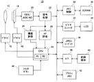
図1を参照して、この実施例の電子カメラ(ディジタルカメラ)10は、フォーカスレンズ12を含む。被写界の光学像は、フォーカスレンズ12を通してイメージセンサ14の受光面つまり撮像面に照射される。撮像面では、光電変換によって被写界の光学像に対応する電荷つまり生画像信号が生成される。
Referring to FIG. 1, an electronic camera (digital camera) 10 of this embodiment includes a
スルー画像処理つまり被写界のリアルタイム動画像をLCDモニタ34に表示する処理を実行するとき、CPU44は、プリ露光および間引き読み出しの繰り返しをドライバ18に命令する。ドライバ18は、イメージセンサ14のプリ露光とこれによって生成された生画像信号の間引き読み出しとを繰り返し実行する。プリ露光および間引き読み出しは、1/30秒毎に発生する垂直同期信号Vsyncに応答して実行される。これによって、被写界の光学像に対応する低解像度の生画像信号が、30fpsのフレームレートでイメージセンサ14から出力される。
When executing through image processing, that is, processing for displaying a real-time moving image of the object scene on the
出力された各フレームの生画像信号は、CDS/AGC/AD回路20によってノイズ除去,レベル調整およびA/D変換の一連の処理を施され、これによってディジタル信号である生画像データが得られる。信号処理回路22は、CDS/AGC/AD回路20から出力された生画像データに白バランス調整,色分離,YUV変換などの処理を施し、YUV形式の画像データを生成する。生成された画像データはメモリ制御回路28によってSDRAM30に書き込まれ、その後同じメモリ制御回路28によって読み出される。ビデオエンコーダ32は、メモリ制御回路28によって読み出された画像データをNTSCフォーマットに従うコンポジットビデオ信号に変換し、変換されたコンポジットビデオ信号をLCDモニタ34に与える。この結果、被写界のスルー画像がモニタ画面に表示される。
The output raw image signal of each frame is subjected to a series of processes of noise removal, level adjustment and A / D conversion by the CDS / AGC /
信号処理回路22から出力された画像データを形成するYデータは、輝度評価回路24にも与えられる。輝度評価回路24は、撮像面に割り当てられた測光エリア(図示せず)に属するYデータを1フレーム期間毎に積分する。CPU44は、こうして求められた積分値つまり輝度評価値を垂直同期信号Vsyncに応答して輝度評価回路24から取り込み、ドライバ18に設定されたプリ露光時間を取り込まれた輝度評価値に基づいて調整する。これによって、モニタ画面に表示されるスルー画像の明るさが適度に調整される。
The Y data forming the image data output from the signal processing circuit 22 is also given to the
シャッタボタン46が半押しされると、撮像面に割り当てられたフォーカスエリア(図示せず)に注目して、次の要領でフォーカス制御が実行される。まず、高速AF処理を実行するべく、ステップ幅W1がドライバ16に設定される。ドライバ16は、垂直同期信号Vsyncが発生する毎に、無限遠側端部から至近側端部に向けてフォーカスレンズ12を1ステップずつ移動させる。
When the
信号処理回路22からは、各ステップで捉えられた被写界像を表す画像データが出力される。AF評価回路26は、このような画像データを形成するYデータから高域周波数成分を抽出し、抽出された高域周波数成分のうちフォーカスエリアに属する高周波成分の絶対値を1フレーム期間毎に積算する。これによって、積分値つまりAF評価値が1フレームに1回の割合で求められる。なお、こうして求められたAF評価値は、“合焦度”と定義できる。
The signal processing circuit 22 outputs image data representing the object scene image captured at each step. The
CPU44は、垂直同期信号Vsyncが発生する毎にAF評価回路26からAF評価値を取り込み、現時点で最大値を示すAF評価値と最大値が検出されたときのフォーカスレンズ12の位置を示すレンズ位置情報とを図2に示すレジスタR1に登録する。フォーカスレンズ12が至近側端部に到達したとき、レジスタR1に登録されたAF評価値は最大値αとして確定し、レジスタR1に登録されたレンズ位置情報は合焦位置よりも2ステップ先の位置を示す。
The
このような高速AF処理が完了すると、低速AF処理を実行するべく、ステップ幅W1よりも短いステップ幅W2がドライバ16に設定される。上述と同様、ドライバ16は、垂直同期信号Vsyncが発生する毎に無限遠側端部から至近側端部に向けてフォーカスレンズ12を1ステップずつ移動させる。AF評価回路26は、信号処理回路22から出力されるYデータに基づいてAF評価値を1フレーム毎に求める。
When such high-speed AF processing is completed, a step width W2 shorter than the step width W1 is set in the
CPU44は、現時点で最大値を示すAF評価値と最大値が検出されたときのフォーカスレンズ12の位置を示すレンズ位置情報とを図2に示すレジスタR2に登録する。フォーカスレンズ12が至近側端部に到達したとき、レジスタR2に登録されたAF評価値が最大値βとして確定し、レジスタR2に登録されたレンズ位置情報は合焦位置よりも2ステップ先の位置を示す。
The
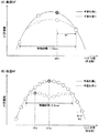
AF評価値は、高速AF処理のとき図3(A)に示す要領で変化する一方、低速AF処理のとき図3(B)に示す要領で変化する。図3(A)および図3(B)から分かるように、高速AF処理の場合にフォーカスレンズ12が合焦位置の近傍を移動するのに要する時間は1/10秒に満たないのに対して、低速AF処理の場合にフォーカスレンズ12が合焦位置の近傍を移動するように要する時間は1/3秒近くに及ぶ。
The AF evaluation value changes in the manner shown in FIG. 3A during high-speed AF processing, and changes in the manner shown in FIG. 3B during low-speed AF processing. As can be seen from FIGS. 3A and 3B, in the case of high-speed AF processing, the time required for the
経験則上、手振れは数秒に1回の割合で発生し、1回の手振れ時間は1/10秒〜1秒である。このため、手振れが発生する確率は、低速AF処理の方が高速AF処理よりも高くなる。また、手振れが発生すると、撮像面で捉えられる被写界像の空間周波数が低下する。このため、手振れがある状態で検出されるAF評価値は、手振れがない状態で検出されるAF評価値よりも小さくなる。 As a rule of thumb, camera shake occurs at a rate of once every few seconds, and one camera shake time is 1/10 second to 1 second. For this reason, the probability that camera shake occurs is higher in the low-speed AF process than in the high-speed AF process. Further, when camera shake occurs, the spatial frequency of the object scene image captured on the imaging surface decreases. For this reason, the AF evaluation value detected in the state where there is camera shake is smaller than the AF evaluation value detected in the state where there is no camera shake.
したがって、高速AF処理の途中で手振れが発生すると、AF評価値はたとえば図3(A)に点線で示すように変化する。また、低速AF処理の途中で手振れが発生すると、AF評価値はたとえば図3(B)に点線で示すように変化する。 Therefore, when camera shake occurs during the high-speed AF process, the AF evaluation value changes as indicated by a dotted line in FIG. 3A, for example. If camera shake occurs during the low-speed AF process, the AF evaluation value changes as indicated by a dotted line in FIG. 3B, for example.
この結果、図3(A)の例では、手振れの有無に関係なく、レンズ位置FP1が合焦位置として検出される。これに対して、図3(B)の例では、手振れがないときはレンズ位置FP2が合焦位置として検出される一方、手振れがあるときはレンズ位置FP3が合焦位置として検出される。このように、低速AF処理時は、高速AF処理時に比べて、合焦位置が誤検出される可能性が高い。 As a result, in the example of FIG. 3A, the lens position FP1 is detected as the in-focus position regardless of the presence or absence of camera shake. On the other hand, in the example of FIG. 3B, the lens position FP2 is detected as the focus position when there is no camera shake, while the lens position FP3 is detected as the focus position when there is camera shake. In this way, the focus position is more likely to be erroneously detected during low-speed AF processing than during high-speed AF processing.
そこで、この実施例では、次の要領で合焦位置を特定し、特定された合焦位置にフォーカスレンズ12を配置するようにしている。まず最大値βを最大値αで割り算し、割り算値β/αを閾値TH1〜TH3の各々と比較する。ここで、割り算値β/αは、低速AF処理によって求められたAF評価値の信頼性を示すパラメータ値であり、高速AF処理によって求められたAF評価値を参照することで算出される。また、閾値TH1〜TH3の間には、TH1<TH2<1<TH3の関係が成り立つ。
Therefore, in this embodiment, the focus position is specified in the following manner, and the
割り算値β/αが閾値TH1以上でかつ閾値TH2未満であれば、最大値βの本来の値からの減少幅は小さいものの、最大値βの信頼性は依然として低いとみなし、高速AF処理によってレジスタR1に登録されたレンズ位置情報に基づいて合焦位置を特定する。 If the divided value β / α is equal to or greater than the threshold value TH1 and less than the threshold value TH2, the maximum value β is considered to be still unreliable although the decrease amount from the original value is small, and is registered by high-speed AF processing. An in-focus position is specified based on the lens position information registered in R1.
割り算値β/αが閾値TH2以上でかつ閾値TH3未満(β/α≒1)であれば、最大値βの信頼性が高いとみなし、低速AF処理によってレジスタR2に登録されたレンズ位置情報に基づいて合焦位置を特定する。 If the divided value β / α is equal to or greater than the threshold value TH2 and less than the threshold value TH3 (β / α≈1), the reliability of the maximum value β is regarded as high, and the lens position information registered in the register R2 by the low-speed AF process is used. Based on this, the in-focus position is specified.
割り算値β/αが閾値TH3以上であれば、最大値αおよびβのいずれの信頼性も低いとみなし、高速AF処理および低速AF処理の両方を再起動する。これによって、最大値αおよびβの両方が再度求められ、新たに算出された割り算値β/αが閾値TH1〜TH3の各々と比較される。 If the divided value β / α is equal to or greater than the threshold value TH3, it is considered that the reliability of the maximum values α and β is low, and both the high-speed AF process and the low-speed AF process are restarted. Thereby, both the maximum values α and β are obtained again, and the newly calculated division value β / α is compared with each of the threshold values TH1 to TH3.
フォーカスレンズ12が合焦位置に配置された後にシャッタボタン46が全押しされると、CPU44によって画像記録処理が実行される。CPU44はまず、本露光および全画素読み出しをドライバ18に命令する。ドライバ18は、イメージセンサ14の本露光とこれによって生成された生画像信号の全画素読み出しとを1回ずつ実行する。これによって、被写界の光学像に対応する高解像度の生画像信号がイメージセンサ14から出力される。出力された生画像信号は上述と同様の処理によってYUV形式の画像データに変換され、変換された画像データはメモリ制御回路28によってSDRAM30に書き込まれる。
When the
CPU44はまた、画像圧縮命令をJPEGコーデック36に向けて発行する。JPEGコーデック36は、メモリ制御回路28を通してSDRAM30から1フレームの画像データを読み出し、読み出された画像データにJPEG圧縮を施し、そして圧縮画像データつまりJPEGデータをメモリ制御回路28を通してSDRAM30に書き込む。CPU44はさらに、メモリ制御回路28を通してSDRAM30からJPEGデータを読み出し、読み出されたJPEGデータを含む画像ファイルをI/F回路38を通して記録媒体40に記録する。このような画像記録処理が完了すると、上述のスルー画像処理が再開される。
The
フォーカスを制御するとき、CPU44は、図4〜図5に示すフロー図に従う処理を実行する。なお、これらのフロー図に対応する制御プログラムは、フラッシュメモリ42に記憶される。
When controlling the focus, the
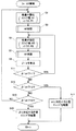
まずステップS1で高速AF設定を行う。これによって、ステップ幅W1がドライバ16に設定され、レジスタR1がAF評価値およびレンズ位置情報の登録先として選択される。ステップS3では、ステップS1の設定に従う高速AF処理を実行する。フォーカスレンズ12はステップ幅W1ずつ光軸方向に移動し、現時点で最大のAF評価値およびこれに対応するレンズ位置情報がレジスタR1に書き込まれる。ステップS3の処理が完了すると、レジスタR1に格納されたAF評価値が最大値αとして確定する。レジスタR1に格納されたレンズ位置情報は、合焦位置よりも2ステップ先の位置を示す。
First, in step S1, high-speed AF setting is performed. As a result, the step width W1 is set in the
ステップS5では低速AF設定を行う。これによって、ステップ幅W2(<W1)がドライバ16に設定され、AF評価値およびレンズ位置情報の登録先としてレジスタR2が選択される。ステップS7では、ステップS5の設定に従う低速AF処理を実行する。フォーカスレンズ12はステップ幅W2ずつ光軸方向に移動し、現時点で最大のAF評価値およびこれに対応するレンズ位置情報がレジスタR2に書き込まれる。ステップS7の処理が完了すると、レジスタR2に格納されたAF評価値が最大値βとして確定する。レジスタR2に格納されたレンズ位置情報は、合焦位置よりも2ステップ先の位置を示す。
In step S5, low speed AF setting is performed. As a result, the step width W2 (<W1) is set in the
ステップS9では、最大値βを最大値αで割り算する。割り算値β/αは、ワークエリア(図示せず)に格納される。ステップS11では割り算値β/αを閾値TH1と比較し、ステップS13では割り算値β/αを閾値TH1と比較し、ステップS15では割り算値β/αを閾値TH3と比較する。上述のように、閾値TH1〜TH3の間にはTH1<TH2<1<TH3の関係が成り立つ。 In step S9, the maximum value β is divided by the maximum value α. The division value β / α is stored in a work area (not shown). In step S11, the division value β / α is compared with the threshold value TH1, in step S13, the division value β / α is compared with the threshold value TH1, and in step S15, the division value β / α is compared with the threshold value TH3. As described above, the relationship TH1 <TH2 <1 <TH3 is established between the thresholds TH1 to TH3.
β/α<TH1と判断されれば、低速AF処理時の手振れに起因して最大値βが本来の値から大きく減少しているとみなし、ステップS11からステップS5に戻る。この結果、低速AF処理を再起動される。TH1≦β/α<TH2と判断されればステップS13からステップS17に進み、レジスタR1に格納されたレンズ位置情報を参照して最大値αに対応する位置にフォーカスレンズ12を配置する。つまり、低速AF処理によって検出された最大値βの信頼性は依然として低いとみなし、高速AF処理によって特定された合焦位置にフォーカスレンズ12を配置する。
If it is determined that β / α <TH1, it is assumed that the maximum value β is greatly reduced from the original value due to camera shake during low-speed AF processing, and the process returns from step S11 to step S5. As a result, the low speed AF process is restarted. If it is determined that TH1 ≦ β / α <TH2, the process proceeds from step S13 to step S17, and the
TH2≦β/α<TH3と判断されればステップS15からステップS19に進み、レジスタR2に格納されたレンズ位置情報を参照して最大値βに対応する位置にフォーカスレンズ12を配置する。つまり、手振れはほとんど生じていないとみなして、低速AF処理によって検出された合焦位置にフォーカスレンズ12を配置する。TH3≦β/αと判断されれば、最大値αおよびβのいずれも信頼できないとみなし、ステップS15からステップS1に戻る。この結果、高速AF処理および低速AF処理の両方が再起動される。
If it is determined that TH2 ≦ β / α <TH3, the process proceeds from step S15 to step S19, and the
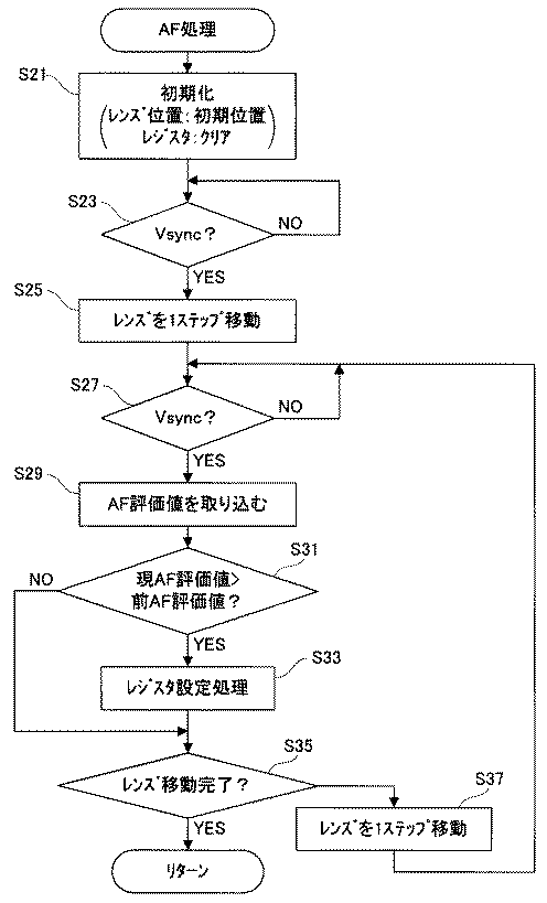
ステップS3およびS7の各々では、図5に示すサブルーチンに従う処理が実行される。まずステップS1で初期化を行う。フォーカスレンズ12は初期位置(無限遠側端部)に配置され、登録先として選択されたレジスタがクリアされる。垂直同期信号Vsyncが発生するとステップS23でYESと判断し、ステップS25でフォーカスレンズ12を至近側に1ステップ移動させる。フォーカスレンズ12は、高速AF処理のときステップ幅W1だけ移動し、低速AF処理のときステップ幅W2だけ移動する。
In each of steps S3 and S7, processing according to the subroutine shown in FIG. 5 is executed. First, initialization is performed in step S1. The
垂直同期信号Vsyncが再度発生すると、ステップS27でYESと判断し、ステップS29でAF評価回路26からAF評価値を取り込む。取り込まれたAF評価値は、2フレーム前に行われたプリ露光に基づく評価値である。ステップS31では、今回取り込まれたAF評価値(現AF評価値)が前回取り込まれたAF評価値(前AF評価値)を上回るか否かを判別する。ここでNOであればそのままステップS35に進む一方、YESであればステップS33の処理を経てステップS35に進む。ステップS33では、今回取り込まれたAF評価値と現時点のフォーカスレンズ12の位置を示すレンズ位置情報とを登録先として選択されたレジスタに書き込む。
When the vertical synchronization signal Vsync is generated again, YES is determined in step S27, and an AF evaluation value is taken in from the
ステップS35では、フォーカスレンズ12が至近側端部に到達したか否かを判別する。NOであれば、ステップS37でフォーカスレンズ12を至近側に1ステップ移動させた後、ステップS27に戻る。YESであれば、上階層のルーチンに復帰する。ステップS35でYESと判断されたとき、登録先のレジスタには、今回のAF処理によって検出された最大AF評価値と合焦位置よりも2ステップ先のレンズ位置を示すレンズ位置情報が格納される。
In step S35, it is determined whether or not the
以上の説明から分かるように、イメージセンサ12は、フォーカスレンズ12を経た被写界像を捉える撮像面を有する。ドライバ16は、フォーカスレンズ12を設定されたステップ幅ずつ至近側に移動させる(S25, S37)。撮像面で捉えられた被写界像のAF評価値を算出する処理は、このようなレンズ移動処理と並行してAF評価回路26によって実行される。CPU44は、共通の設定幅を参照したレンズ移動処理に関連してAF評価回路26によって求められる複数のAF評価値の中から、最大値を検出する(S33)。
As can be seen from the above description, the
CPU44は、高速AF処理を実行するときステップ幅W1をドライバ16に設定し(S1)、低速AF処理を実行するときステップ幅W2(<W1)をドライバ16に設定する(S5)。CPU44はまた、高速AF処理によって検出される最大値αが低速AF処理によって検出される最大値βに占める割合(=β/α:割り算値)を算出する(S9)。CPU44は、算出された割り算値β/αが既定数値範囲(閾値TH1以上で閾値TH3未満の範囲)に属するとき、最大値αおよびβに基づいて合焦点を特定する(S17, S19)。CPU44はまた、割り算値β/αが既定数値範囲から下側に外れるとき低速AF処理を再起動する(S11)。
The
手振れが発生すると、撮像面で捉えられる被写界像の空間周波数が低下する。したがって、手振れがある状態で検出されるAF評価値は、手振れがない状態で検出されるAF評価値よりも小さくなる。また、ステップ幅W2に従うレンズ移動処理に要する時間は、ステップ幅W1に従うレンズ移動処理に要するよりも長い。したがって、ステップ幅W2に従うレンズ移動処理の途中で手振れが発生する確率は、ステップ幅W1に従うレンズ移動処理の途中で手振れが発生する確率よりも高くなる。 When camera shake occurs, the spatial frequency of the object scene image captured on the imaging surface decreases. Therefore, the AF evaluation value detected in the state where there is camera shake is smaller than the AF evaluation value detected in the state where there is no camera shake. Further, the time required for the lens movement process according to the step width W2 is longer than that required for the lens movement process according to the step width W1. Accordingly, the probability that camera shake occurs during the lens movement process according to the step width W2 is higher than the probability that camera shake occurs during the lens movement process according to the step width W1.
このような性質を考慮して、この実施例では、割り算値β/αが既定数値範囲から下側に外れるとき(最大値βが予想以上に低下したとき)、低速AF処理の途中で手振れが発生したとみなし、低速AF処理を再度実行するようにしている。再度の低速AF処理によって求められた最大値βが前回求められた最大値βよりも大きく、割り算値β/αが既定数値範囲に属することとなったときは、最大値αおよびβに基づいて合焦点が特定される。これによって、手振れに関らずフォーカスを的確に調整することができる。 In consideration of such characteristics, in this embodiment, when the divided value β / α deviates from the predetermined numerical value range (when the maximum value β is lowered more than expected), camera shake may occur during the low-speed AF process. The low-speed AF process is executed again, assuming that it has occurred. When the maximum value β obtained by the low-speed AF process again is larger than the previously obtained maximum value β and the divided value β / α belongs to the predetermined numerical value range, the maximum values α and β are used. The focal point is identified. As a result, the focus can be accurately adjusted regardless of camera shake.
なお、この実施例では、フォーカスレンズl2を光軸方向に移動させるようにしているが、フォーカスレンズ12に代えて或いはフォーカスレンズ12とともにイメージセンサ14を光軸方向に移動させるようにしてもよい。
In this embodiment, the
10 …ディジタルカメラ
12 …フォーカスレンズ
14 …イメージセンサ
16,18 …ドライバ
26 …AF評価回路
44 …CPU
DESCRIPTION OF
Claims (7)
前記レンズから前記撮像面までの距離を設定幅ずつ変更する変更手段、
前記撮像面で捉えられた被写界像の合焦度を前記変更手段の変更処理と並行して検出する検出手段、
第1変更幅を前記変更手段に設定する第1設定手段、
前記第1変更幅よりも短い第2変更幅を前記変更手段に設定する第2設定手段、
前記第2設定手段の設定に対応して前記検出手段によって検出された合焦度の信頼性を示すパラメータ値を前記第1設定手段の設定に対応して前記検出手段によって検出された合焦度の大きさに対する前記第2設定手段の設定に対応して前記検出手段によって検出された合焦度の大きさの割合として算出する算出手段、
前記算出手段によって算出されたパラメータ値が既定値範囲に属するとき前記検出手段によって検出された合焦度に基づいて前記レンズから前記撮像面までの適正距離を決定する決定手段、および
前記算出手段によって算出されたパラメータ値が前記既定値範囲から下側に外れるとき前記検出手段を前記第2設定手段の設定に対応した状態でのみ再起動する第1再起動手段を備える、電子カメラ。 An imaging means having an imaging surface for capturing an object scene image that has passed through a lens;
Changing means for changing the distance from the lens to the imaging surface by a set width;
Detecting means for detecting the degree of focus of the object scene image captured on the imaging surface in parallel with the changing process of the changing means;
First setting means for setting a first change width in the changing means;
A second setting means for setting a second change width shorter than the first change width in the change means;
A parameter value indicating the reliability of the degree of focus detected by the detection unit corresponding to the setting of the second setting unit is used as a focus value detected by the detection unit corresponding to the setting of the first setting unit. Calculating means for calculating a ratio of the magnitude of the degree of focus detected by the detecting means corresponding to the setting of the second setting means with respect to the magnitude of
A determination unit that determines an appropriate distance from the lens to the imaging surface based on a degree of focus detected by the detection unit when the parameter value calculated by the calculation unit belongs to a predetermined value range; and the calculation unit calculated parameter value comprises a first re-starting means for only restarted in the state that corresponds to the detecting means when the outside on the lower side from the predetermined value range of the setting of the second setting means, an electronic camera.
前記第1設定手段は前記第2設定手段の設定処理に先立って設定処理を実行する、請求項1ないし4のいずれかに記載の電子カメラ。 It further comprises a receiving means for receiving a distance adjustment operation,
The electronic camera according to claim 1, wherein the first setting unit executes a setting process prior to the setting process of the second setting unit.
第1変更幅を前記変更手段に設定する第1設定ステップ、
前記第1変更幅よりも短い第2変更幅を前記変更手段に設定する第2設定ステップ、
前記第2設定ステップの設定に対応して前記検出手段によって検出された合焦度の信頼性を示すパラメータ値を前記第1設定ステップの設定に対応して前記検出手段によって検出された合焦度の大きさに対する前記第2設定ステップの設定に対応して前記検出手段によって検出された合焦度の大きさの割合として算出する算出ステップ、
前記算出ステップによって算出されたパラメータ値が既定数値範囲に属するとき前記検出手段によって検出された合焦度に基づいて前記レンズから前記撮像面までの適正距離を決定する決定ステップ、および
前記算出ステップによって算出されたパラメータ値が前記既定値範囲から下側に外れるとき前記検出手段を前記第2設定ステップの設定に対応した状態でのみ再起動する再起動ステップを実行させるための、距離制御プログラム。 Imaging means having an imaging surface for capturing an object scene image that has passed through a lens, changing means for changing the distance from the lens to the imaging surface by a set width, and the degree of focus of the object scene image captured on the imaging surface In the processor of the electronic camera provided with detection means for detecting in parallel with the change process of the change means,
A first setting step of setting a first change width in the changing means;
A second setting step of setting a second change width shorter than the first change width in the changing means;
A parameter value indicating the reliability of the degree of focus detected by the detection unit corresponding to the setting of the second setting step is used as the degree of focus detected by the detection unit corresponding to the setting of the first setting step. A calculation step of calculating as a ratio of the magnitude of the degree of focus detected by the detection means corresponding to the setting of the second setting step with respect to the magnitude of
A determination step for determining an appropriate distance from the lens to the imaging surface based on a degree of focus detected by the detection means when the parameter value calculated by the calculation step belongs to a predetermined numerical value range; and for calculated parameter values to perform the restarting step of only restarted in the state that corresponds to the detecting means when the outside on the lower side from the predetermined value range of the setting of the second setting step, a distance control program.
第1変更幅を前記変更手段に設定する第1設定ステップ、
前記第1変更幅よりも短い第2変更幅を前記変更手段に設定する第2設定ステップ、
前記第2設定ステップの設定に対応して前記検出手段によって検出された合焦度の信頼性を示すパラメータ値を前記第1設定ステップの設定に対応して前記検出手段によって検出された合焦度の大きさに対する前記第2設定ステップの設定に対応して前記検出手段によって検出された合焦度の大きさの割合として算出する算出ステップ、
前記算出ステップによって算出されたパラメータ値が既定値範囲に属するとき前記検出手段によって検出された合焦度に基づいて前記レンズから前記撮像面までの適正距離を決定する決定ステップ、および
前記算出ステップによって算出されたパラメータ値が前記既定数値範囲から下側に外れるとき前記検出手段を前記第2設定ステップの設定に対応した状態でのみ再起動する再起動ステップを備える、距離制御方法。 Imaging means having an imaging surface for capturing an object scene image that has passed through a lens, changing means for changing the distance from the lens to the imaging surface by a set width, and the degree of focus of the object scene image captured on the imaging surface A distance control method executed by an electronic camera provided with a detecting means for detecting in parallel with the changing process of the changing means,
A first setting step of setting a first change width in the changing means;
A second setting step of setting a second change width shorter than the first change width in the changing means;
A parameter value indicating the reliability of the degree of focus detected by the detection unit corresponding to the setting of the second setting step is used as the degree of focus detected by the detection unit corresponding to the setting of the first setting step. A calculation step of calculating as a ratio of the magnitude of the degree of focus detected by the detection means corresponding to the setting of the second setting step with respect to the magnitude of
A determination step of determining an appropriate distance from the lens to the imaging surface based on a degree of focus detected by the detection means when the parameter value calculated by the calculation step belongs to a predetermined value range; and by the calculation step calculated parameter values comprises a restart step of only restarted in the state that corresponds to the detection means to set the second setting step when deviating downward from the predetermined numerical value range, the distance control method.
Priority Applications (1)
| Application Number | Priority Date | Filing Date | Title |
|---|---|---|---|
| JP2006164118A JP4936799B2 (en) | 2006-06-14 | 2006-06-14 | Electronic camera |
Applications Claiming Priority (1)
| Application Number | Priority Date | Filing Date | Title |
|---|---|---|---|
| JP2006164118A JP4936799B2 (en) | 2006-06-14 | 2006-06-14 | Electronic camera |
Publications (2)
| Publication Number | Publication Date |
|---|---|
| JP2007333909A JP2007333909A (en) | 2007-12-27 |
| JP4936799B2 true JP4936799B2 (en) | 2012-05-23 |
Family
ID=38933462
Family Applications (1)
| Application Number | Title | Priority Date | Filing Date |
|---|---|---|---|
| JP2006164118A Expired - Fee Related JP4936799B2 (en) | 2006-06-14 | 2006-06-14 | Electronic camera |
Country Status (1)
| Country | Link |
|---|---|
| JP (1) | JP4936799B2 (en) |
Families Citing this family (2)
| Publication number | Priority date | Publication date | Assignee | Title |
|---|---|---|---|---|
| JP5063381B2 (en) * | 2008-01-17 | 2012-10-31 | 三洋電機株式会社 | Electronic camera |
| JP2010134210A (en) * | 2008-12-05 | 2010-06-17 | Sanyo Electric Co Ltd | Electronic camera |
Family Cites Families (3)
| Publication number | Priority date | Publication date | Assignee | Title |
|---|---|---|---|---|
| JPS63125910A (en) * | 1986-11-17 | 1988-05-30 | Sanyo Electric Co Ltd | Automatic focusing circuit |
| JP4241591B2 (en) * | 2001-08-10 | 2009-03-18 | キヤノン株式会社 | Lens barrel |
| JP2005266784A (en) * | 2004-02-18 | 2005-09-29 | Canon Inc | Imaging apparatus, control method thereof, control program thereof, and storage medium |
-
2006
- 2006-06-14 JP JP2006164118A patent/JP4936799B2/en not_active Expired - Fee Related
Also Published As
| Publication number | Publication date |
|---|---|
| JP2007333909A (en) | 2007-12-27 |
Similar Documents
| Publication | Publication Date | Title |
|---|---|---|
| JP5088118B2 (en) | Focus adjustment device | |
| CN103733607B (en) | For detecting the apparatus and method of moving object | |
| US8988529B2 (en) | Target tracking apparatus, image tracking apparatus, methods of controlling operation of same, and digital camera | |
| US8717490B2 (en) | Imaging apparatus, focusing method, and computer-readable recording medium recording program | |
| JP4980982B2 (en) | Imaging apparatus, imaging method, focus control method, and program | |
| KR101625893B1 (en) | Image pickup apparatus that periodically changes exposure condition, a method of controlling image pickup apparatus, and storage medium | |
| JP4887275B2 (en) | Imaging apparatus and shutter drive mode selection method thereof | |
| JP6137840B2 (en) | Camera system | |
| JP4286292B2 (en) | Electronic camera | |
| US20130293766A1 (en) | Imaging device and main photographic subject recognition method | |
| US10237488B2 (en) | Image capturing apparatus and image capturing method | |
| US8471953B2 (en) | Electronic camera that adjusts the distance from an optical lens to an imaging surface | |
| US20100149342A1 (en) | Imaging apparatus | |
| KR20150078275A (en) | Digital Photographing Apparatus And Method For Capturing a Moving Subject | |
| US7567753B2 (en) | Video camera and image extracting apparatus utilized for same | |
| JP5407373B2 (en) | Imaging apparatus and program | |
| JP4936799B2 (en) | Electronic camera | |
| JP2007052061A (en) | Imaging apparatus, focusing operation control method, and electronic information device | |
| JP5195663B2 (en) | Imaging apparatus, focusing method, and program | |
| KR101720775B1 (en) | Photoghraphing apparatus and method | |
| JP5477345B2 (en) | Imaging apparatus, focusing method, and program | |
| JP2006079069A (en) | Electronic camera | |
| JP5561392B2 (en) | Imaging apparatus, focusing method, and program | |
| JP2010169825A (en) | Imaging device | |
| JP4420651B2 (en) | Optical device |
Legal Events
| Date | Code | Title | Description |
|---|---|---|---|
| A621 | Written request for application examination |
Free format text: JAPANESE INTERMEDIATE CODE: A621 Effective date: 20090601 |
|
| A977 | Report on retrieval |
Free format text: JAPANESE INTERMEDIATE CODE: A971007 Effective date: 20110217 |
|
| A131 | Notification of reasons for refusal |
Free format text: JAPANESE INTERMEDIATE CODE: A131 Effective date: 20110222 |
|
| A521 | Request for written amendment filed |
Free format text: JAPANESE INTERMEDIATE CODE: A523 Effective date: 20110425 |
|
| A131 | Notification of reasons for refusal |
Free format text: JAPANESE INTERMEDIATE CODE: A131 Effective date: 20110726 |
|
| A521 | Request for written amendment filed |
Free format text: JAPANESE INTERMEDIATE CODE: A523 Effective date: 20110926 |
|
| TRDD | Decision of grant or rejection written | ||
| A01 | Written decision to grant a patent or to grant a registration (utility model) |
Free format text: JAPANESE INTERMEDIATE CODE: A01 Effective date: 20120124 |
|
| A01 | Written decision to grant a patent or to grant a registration (utility model) |
Free format text: JAPANESE INTERMEDIATE CODE: A01 |
|
| A61 | First payment of annual fees (during grant procedure) |
Free format text: JAPANESE INTERMEDIATE CODE: A61 Effective date: 20120221 |
|
| FPAY | Renewal fee payment (event date is renewal date of database) |
Free format text: PAYMENT UNTIL: 20150302 Year of fee payment: 3 |
|
| FPAY | Renewal fee payment (event date is renewal date of database) |
Free format text: PAYMENT UNTIL: 20150302 Year of fee payment: 3 |
|
| FPAY | Renewal fee payment (event date is renewal date of database) |
Free format text: PAYMENT UNTIL: 20150302 Year of fee payment: 3 |
|
| S111 | Request for change of ownership or part of ownership |
Free format text: JAPANESE INTERMEDIATE CODE: R313113 |
|
| FPAY | Renewal fee payment (event date is renewal date of database) |
Free format text: PAYMENT UNTIL: 20150302 Year of fee payment: 3 |
|
| R350 | Written notification of registration of transfer |
Free format text: JAPANESE INTERMEDIATE CODE: R350 |
|
| LAPS | Cancellation because of no payment of annual fees |