JP4936728B2 - Civil engineering bag - Google Patents
Civil engineering bag Download PDFInfo
- Publication number
- JP4936728B2 JP4936728B2 JP2006003074A JP2006003074A JP4936728B2 JP 4936728 B2 JP4936728 B2 JP 4936728B2 JP 2006003074 A JP2006003074 A JP 2006003074A JP 2006003074 A JP2006003074 A JP 2006003074A JP 4936728 B2 JP4936728 B2 JP 4936728B2
- Authority
- JP
- Japan
- Prior art keywords
- tissue
- civil engineering
- yarn
- bag
- insertion space
- Prior art date
- Legal status (The legal status is an assumption and is not a legal conclusion. Google has not performed a legal analysis and makes no representation as to the accuracy of the status listed.)
- Active
Links
Images


Landscapes
- Revetment (AREA)
Description
本発明は、土砂や栗石、コンクリートガラ等の中詰め材が充填される土木用袋体に関する。
より詳しくは、河川や港湾等において洗堀や侵食を防止するために用いられる根固め用、更には落石、雪崩、土砂崩れ等を防止するための衝撃吸収防護壁用に使われる土嚢袋に関するものである。
TECHNICAL FIELD The present invention relates to a civil engineering bag filled with filling materials such as earth and sand, chestnut stone, and concrete glass.
More specifically, it relates to sandbags used for root consolidation used to prevent scouring and erosion in rivers and harbors, as well as shock absorbing protective walls used to prevent falling rocks, avalanches and landslides. is there.
従来、河川や港湾等において洗堀や侵食を防止するために土砂等を投入した土木用袋体が使用されている。
この袋体は、開口部や底部をロープや紐等により絞り込むことにより、巾着状にするタイプが多い。
そのため製造時において、筒状の布袋の開口部や底部を折り返して縫着し、ロープや紐を挿通するための通路を形成しておく。
そして、製造時や施工現場では、この通路にロープや紐を挿通した後、それを引張って開口部や底部を絞り込む手順を取る(例えば、特許文献1参照)。
また、布袋が明確な網目を有する場合は、製造時において、口絞り糸を布袋の開口部の網目に交互にうねらせて挿通することにより開口部に取り付けておき、施工現場で同様な手順により開口部を絞り込む。
Conventionally, in order to prevent scouring and erosion in rivers, harbors, etc., civil engineering pouches filled with earth and sand have been used.
In many cases, the bag body has a purse-like shape by narrowing the opening and bottom with a rope or string.
Therefore, at the time of manufacture, the opening part and bottom part of a cylindrical cloth bag are folded back and sewn to form a passage for inserting a rope or string.
And at the time of manufacture or at the construction site, after a rope or string is inserted through this passage, a procedure is taken to narrow the opening and bottom by pulling it (for example, see Patent Document 1).
In addition, when the fabric bag has a clear mesh, it is attached to the opening by alternately squeezing the squeezed yarn through the mesh of the opening of the fabric bag at the time of manufacture. Narrow the opening.
しかしながら、上述したような土木用袋体では、開口部や底部を折り返して縫着しロープや紐を挿通するための通路を形成する作業と、この通路にロープを挿通する作業とが必要である。
この縫製による通路の形成方法では、工数が増えて手間がかかる上、通路の幅が個々に不均一になり易いという欠点がある。
また、布袋が明確な網目を有する場合は、絞り糸を布袋の開口部や底部の網目に交互にうねらせて挿入する作業が必要であり、特に網目に絞り糸を迅速且つ均一に挿入していくためには作業に熟練を要する。
However, in the civil engineering bag as described above, it is necessary to fold back the opening and bottom and sew and form a passage for inserting the rope and string, and to insert the rope into the passage. .
This method of forming a passage by sewing has the disadvantages that the number of man-hours is increased and labor is required, and the width of the passage tends to be non-uniform individually.
In addition, when the cloth bag has a clear mesh, it is necessary to insert the squeezing yarn alternately in the mesh at the opening and bottom of the cloth bag. It takes skill to work.
本発明は、上述した課題を解決するためになされたものである。
すなわち、本発明は、製造時において、布袋の開口部や底部に絞り糸を設けるのに極力手間がかからない土木用袋体を提供することを目的とする。
The present invention has been made to solve the above-described problems.
That is, an object of the present invention is to provide a civil engineering bag body that does not require as much effort as possible to provide a drawn thread at the opening or bottom of the cloth bag during manufacture.
かくして、本発明者は、このような課題背景に対して鋭意研究を重ねた結果、布袋を製織により製造し、この製織の際、同時に口絞り糸や底絞り糸を組織的に形成された挿入空間部に挿入することにより、上記のような問題点を解決することができることを見出し、この知見に基づいて本発明を完成させたものである。 Thus, as a result of intensive research on the background of such problems, the present inventor manufactured a fabric bag by weaving, and at the same time of weaving, the mouth-drawn yarn and the bottom-drawn yarn were systematically formed and inserted. It has been found that the above-mentioned problems can be solved by inserting into the space portion, and the present invention has been completed based on this finding.
すなわり、本発明は、(1)、開口部と胴体部と底部とを有する巾着状の布袋よりなり、開口部に口絞り糸が設けられ且つ底部に底絞り糸が設けられた土木用袋体であって、前記口絞り糸及び底絞り糸は布袋の製織時に挿入されたものであり、前記開口部及び胴体部が、前面部を形成する前面組織部と後面部を形成する後面組織部とよりなり、開口部の各組織部の一部に横方向の挿入空間部が形成され、該挿入空間部に緯入れにより前記口絞り糸が挿入されており、前記底部が一体組織部よりなり、該一体組織部の一部に横方向の挿入空間部が形成され、該挿入空間部に緯入れにより前記底絞り糸が挿入されている土木用袋体に存する。 In other words, the present invention is (1) for civil engineering comprising a purse-like cloth bag having an opening, a body portion, and a bottom, and having a mouth-drawn yarn at the opening and a bottom-drawn yarn at the bottom. A squeezing thread and a bottom squeezing thread, which are inserted when weaving a cloth bag, and the opening and the body part form a front part forming a front part and a rear part structure forming a rear part. A lateral insertion space portion is formed in a part of each tissue portion of the opening, and the mouth-drawn yarn is inserted into the insertion space portion by weft insertion, and the bottom portion is formed from the integral tissue portion. Therefore, the present invention resides in a civil engineering bag body in which a lateral insertion space portion is formed in a part of the integrated tissue portion, and the bottom drawn yarn is inserted into the insertion space portion by weft insertion .
また、本発明は、(2)、前記底部の一体組織部は胴体部の前面組織部と後面組織部とが一体化した組織となっている上記(1)記載の土木用袋体に存する。 Further, the present invention is (2), integral structure part of the bottom consists in civil engineering bag body (1), characterized in that a tissue and the front structure part and rear structure of the body part are integrated.
また、本発明は、(3)、前記胴体部には中詰め材の投入量を示す着色した緯糸が織り込まれている(1)記載の土木用袋体に存する。 The present invention also relates to (3), the colored weft showing the input of the medium filling material in the body portion is woven (1) consists in civil engineering bag body according.
また、本発明は、(4)、前記布袋の両側は一定幅に渡って前面組織部と後面組織部とが一体化した一体組織部となっている上記(1)記載の土木用袋体に存する。 The invention also relates to (4), both sides of the sack in the civil engineering for bag according to (1), which is a front tissue section and the rear surface tissue section are integrated tissue portion that is integrated over a constant width Exist.
また、本発明は、(5)、前記布袋の両側の一体組織部には吊り上げ用の穴が形成されている上記(4)記載の土木用袋体に存する。 Moreover, this invention exists in the civil engineering bag body of the said ( 4 ) description by which the hole for lifting is formed in the integral structure part of the both sides of the said cloth bag ( 5 ).
また、本発明は、(6)、前記口絞り糸及び底絞り糸は、他の組織部を構成する糸より補強された太糸である上記(1)記載の土木用袋体に存する。 The invention also relates to (6), thread stop the mouth aperture yarns and bottom lies in civil engineering bag body (1), wherein the thick yarn reinforced from the yarn constituting the other tissue portion.
なお、本発明の目的に添ったものであれば、上記発明を適宜組み合わせた構成も採用可能である。 In addition, as long as the objective of this invention is met, the structure which combined the said invention suitably is also employable.
本発明の土木用袋体によれば、口絞り糸及び底絞り糸は布袋の製織時に挿入され、製織時にロープを挿入する挿入空間部が組織的に形成されるので、従来のようにわざわざ縫製等により口絞りロープの挿入空間部を別工程で作る必要がなく、また挿入空間部に口絞りロープを挿入する操作も不必要である。
よって全体的に製造工数が少なくなり土木用袋体自体の品質も向上する。
According to the civil engineering bag of the present invention, the mouth squeezing yarn and the bottom squeezing yarn are inserted during weaving of the cloth bag, and the insertion space for inserting the rope during weaving is systematically formed. Thus, it is not necessary to make the insertion space portion of the mouthpiece rope in a separate process, and the operation of inserting the mouthpiece rope into the insertion space portion is unnecessary.
Therefore, the manufacturing man-hour is reduced as a whole, and the quality of the civil engineering bag itself is improved.
以下、本発明を実施するための最良の形態を図面を用いて説明する。
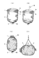
図1は、中詰め材Wが投入される前の土木用袋体を示しており、また図2は中詰め材Wが投入された後の土木用袋体を示している。
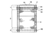
更に図3は、土木用袋体の組織を説明するための長さ方向の断面図である。
この実施形態の土木用袋体は、織機を使って製織される巾着状で矩形の布袋Aよりなり、該布袋Aは開口部1と胴体部2と底部3とを有する。
そして土木用袋体は、胴体部2に中詰め材Wが所定の量だけ投入された状態(すなわち充填された状態)では立体形状を呈するものである。
開口部1及び胴体部2は前面部と後面部とよりなり、これらの部分を広げると中詰め材Wの投入空間Sが形成される。
に存する。
The best mode for carrying out the present invention will be described below with reference to the drawings.
FIG. 1 shows the civil engineering bag body before the filling material W is introduced, and FIG. 2 shows the civil engineering bag body after the filling material W is introduced.
Further, FIG. 3 is a longitudinal sectional view for explaining the structure of the civil engineering bag.
The civil engineering bag body of this embodiment is formed of a drawstring-like rectangular cloth bag A woven using a loom, and the cloth bag A has an
The civil engineering bag has a three-dimensional shape in a state where a predetermined amount of the filling material W is charged into the body portion 2 (that is, a state in which the filling material W is filled).
The
Exist.
中詰め材Wとしては、主として土砂や栗石、コンクリートガラ等が採用されるが、使用用途によっては他の種々のものが使用可能である。 As the filling material W, mainly earth and sand, chestnut stone, concrete glass or the like is adopted, but other various materials can be used depending on the intended use.
また、布袋Aの材質としては、中詰め材Wを投入可能な強度を有するものであればよく、ポリエステル、ポリアミド、ポリエチレン、又はポリプロピレン等の合成繊維や綿、麻等の天然繊維が採用される。 Moreover, as a material of the cloth bag A, what is necessary is just to have the intensity | strength which can insert the filling material W, Natural fibers, such as synthetic fibers, such as polyester, polyamide, polyethylene, or polypropylene, and cotton, hemp, are employ | adopted. .
土木用袋体において開口部1や胴体部2の前面部は前面組織部1Aにより形成され、また後面部は後面組織部1Bにより形成されており、これら両組織部1A,1Bが底部3において一体化され一体組織部3ABを形成しているものである。
ここで、これらの各組織部1A,1Bは織機によって製織され、その製織時に例えば平織組織として織り込まれていくものであり、いわゆる織組織を構成する。
底部3における一体組織部3ABの織密度は、開口部1及び胴体部2における前面組織部1A及び後面組織部1Bの織密度の2倍となる。
更にいうと、製織時における縦糸や緯糸の(緯糸の調製はどの部分でも可能である)糸密度は、一体組織部3ABでは前面組織部1Aや後面組織部1Bの2倍の糸密度を有するものである。
なお、各組織の密度は緯入れする緯糸の本数により調整することができる。
In the civil engineering bag body, the front surface portion of the
Here, each of these
The woven density of the monolithic tissue part 3AB in the
Furthermore, the yarn density of the warp and weft during weaving (weft preparation is possible at any part) has a yarn density twice that of the
The density of each structure can be adjusted by the number of wefts to be inserted.
(開口部)
ところで本発明の土木用袋体は、開口部1に口絞り糸R1が設けられ且つ底部3に底絞り糸R2が設けられており、これらは絞り込みのため機能する。
(Aperture)
By the way, the civil engineering bag of the present invention is provided with a mouth-drawn yarn R1 at the opening 1 and a bottom-drawn yarn R2 at the
詳しくは、開口部1には、製織時に前面組織部1A及び後面組織部1Bの一部に横方向の挿入空間部S1が形成されると、この挿入空間部S1に口絞り糸R1が挿入されている。
この場合、開口部1を織機で製織する際、前面組織部1Aが挿入空間部S1を作るための二枚の前薄組織部1A1,1A1に分離組織化され、同様に後面組織部1Bも挿入空間部S1を作るための二枚の後薄組織部1B1,1B1に分離組織化される。
前面組織部1Aは前薄組織部1A1の織密度の2倍であり、同様に後面組織部1Bも後薄組織部1B1の織密度の2倍となる。
Specifically, when a lateral insertion space S1 is formed in a part of the
In this case, when weaving the
The
製織時の縦糸や緯糸でいうと、それらの糸密度は前面組織部1Aや後面組織部1Bにおいて、それぞれ前薄組織部1A1や後薄組織部1B1の2倍の糸密度となっている。
口絞り糸R1は二枚の前薄組織部1A1により形成された挿入空間部S1に横方向に一方通行で挿入されており、また二枚の後薄組織部1B1により形成された挿入空間部S1に横方向に一方通行で挿入されており、計2本となる。
これらの口絞り糸R1の挿入は、製織時に例えばレピアグリッパを使って緯入れにより一方通行に挿入することが可能である。
In the case of warp and weft during weaving, the yarn density of the
The squeezed yarn R1 is inserted in the insertion space S1 formed by the two front thin tissue portions 1A1 by one-way in the lateral direction, and the insertion space portion S1 formed by the two rear thin tissue portions 1B1. Are inserted in one direction in the horizontal direction, and there are a total of two.
These squeezed yarns R1 can be inserted in one way by weft insertion using, for example, a rapier gripper during weaving.
挿入空間部S1は、従来のように縫製代を取って縫い込むようなことがないため、内部に縫い代の部分が顔を出さず、その結果、織組織により形成された真っ直ぐで均一な空間となり、且つ従来に較べて縫い代による硬さが少なる。
またこの口絞り糸R1は該糸に較べて広めの挿入空間部S1に自由度を有する状態で配置されている。
このようなことから口絞り糸R1により開口部1を絞り込む際には、均一な絞り込みができ、更に極めて作業がし易いものとなる。
Since the insertion space S1 does not sew with a sewing allowance unlike the conventional case, the portion of the sewing allowance does not appear inside, and as a result, a straight and uniform space formed by the woven structure is formed. In addition, the hardness due to the seam allowance is less than in the prior art.
The squeezed yarn R1 is arranged in a state having a degree of freedom in the insertion space S1 that is wider than the yarn.
For this reason, when narrowing the
(底部)
一方、底部3は一体組織部3ABとなっているが、この一体組織部3ABの一部にも横方向の挿入空間部S2が形成される。
この場合、一体組織部3ABが挿入空間部S2を作るために前面組織部3Aと後面組織部3Bとに分離されており、これらは開口部1や胴体部2における前面組織部1Aと後面組織部1Bに相当する組織である。
この場合も挿入空間部S2は、従来のように縫い代を作り折り返して縫製するようなことがなく、底絞り糸R2も該糸に較べて広めの挿入空間部S2に自由度を有する状態で配置されている。
このようなことから底部のいわゆる硬さが低下して底絞り糸R2によって極めて絞り込み易くなり、且つ底部3を絞り込む際により操作し易い。
(bottom)
On the other hand, the
In this case, the monolithic tissue portion 3AB is separated into the
Also in this case, the insertion space portion S2 is not sewed by making a seam allowance unlike the conventional case, and the bottom drawn thread R2 is also arranged in a state having a degree of freedom in the insertion space portion S2 that is wider than the thread. Has been.
For this reason, the so-called hardness of the bottom portion is reduced, it is very easy to narrow down by the bottom drawn yarn R2, and it is easier to operate when narrowing the
因みに、従来のように縫製によって挿入空間部S2を形成した場合は、底部を絞り込む場合に硬さが邪魔して滑らかな絞りができない。
製織時、この前面組織部3Aと後面組織部3Bとにより挿入空間部S2が形成され、同時にこの挿入空間部S2に底絞り糸R2が前述した口絞り糸R1のように緯入れによって挿入されることとなる。
Incidentally, in the case where the insertion space portion S2 is formed by sewing as in the conventional case, when the bottom portion is narrowed down, the hardness is obstructed and smooth drawing cannot be performed.
At the time of weaving, an insertion space portion S2 is formed by the
(両側組織)
布袋Aの両側は、一定幅に渡って前面組織部1A,2A,3Aと後面組織部1B,2B,3B,とが一体化した一体組織部Zとなっており、丁度、底部3の一体組織部3ABと同様な織組織である。
従って、中詰め材Wを投入するための投入空間(充填空間)Sは、この両側に形成された一体組織部Zと底部3に形成された一体組織部3ABとにより三方が閉じられた空間となる。
一方側の一体組織部Zには縦方向に一定間隔をおいて穴Hが形成されており、この穴Hは吊り上げ用の穴として用いられる。
すなわち、現場で施工する場合に、中詰め材Wが充填されている土木用袋体は極めて重く(例えば1トン以上になる場合が多い)クレーン等を使用してフックFを、その穴Hに挿入し吊り上げて移動する。
(Bilateral organization)
Both sides of the cloth bag A are integrated tissue portions Z in which the
Therefore, the charging space (filling space) S for charging the filling material W is a space in which three sides are closed by the integral tissue portion Z formed on both sides and the integral tissue portion 3AB formed on the
Holes H are formed in the monolithic tissue portion Z on the one side at regular intervals in the vertical direction, and the holes H are used as lifting holes.
That is, when constructing at the site, the civil engineering bag body filled with the filling material W is extremely heavy (for example, it is often 1 ton or more) and the hook F is inserted into the hole H using a crane or the like. Insert, lift and move.
ところで、上述したように中詰め材Wを充填する際、その投入量を正確にする必要があり、そのために、図1に示すように、布袋Aの胴体部2に、中詰め材Wの投入量の目安となるライン状の目印を設けることが好ましい。
この目印は、製織の際、緯糸として、例えば蛍光色、鮮明色等の目立った着色した緯糸Lを織り込んで使うことにより容易に付与することができる。
中詰め材Wの投入量が正確となり安定することで、設定重量をオーバするようなことが回避され袋自体の品質がよくなり施工設計に沿って正確に施工できる。
By the way, when filling the filling material W as described above, it is necessary to make the amount of the filling accurate, and for this reason, as shown in FIG. 1, the filling material W is put into the
This mark can be easily provided by weaving, for example, a weft L that is conspicuously colored such as a fluorescent color or a clear color as a weft during weaving.
Since the amount of filling of the filling material W is accurate and stable, it is possible to avoid exceeding the set weight, improve the quality of the bag itself, and perform construction accurately according to the construction design.
(作業工程)
次に、土木用袋体に中詰め材W(例として便宜的に小石で示した)を投入する作業手順を述べる。
図4は、土木用袋体に中詰め材Wを投入して使用状態とするまでの作業手順を示した説明図である。
先ず、図1に示すような中詰め材Wを投入する前の状態の土木用袋体から、底絞り糸R2を使って底部3を絞り状態とする〔図4(A)参照〕。
この場合、底絞り糸R2は一体組織部3ABに形成された挿入空間部S2に横方向に一本挿入されているため、底絞り糸R2の両端を持って底部3を回し込むように絞り、その後は更に底絞り糸R2を幾重にも巻回することが好ましい。
(Working process)
Next, an operation procedure for putting the filling material W (shown as pebbles as an example for convenience) into the civil engineering bag will be described.
FIG. 4 is an explanatory view showing a work procedure until the filling material W is put into the civil engineering bag body and put into use.
First, from the civil engineering bag body before the filling material W as shown in FIG. 1 is put in, the
In this case, the bottom squeezing thread R2 is inserted in the insertion space part S2 formed in the integral tissue part 3AB in the lateral direction, so that the bottom squeezing thread R2 is squeezed so that the
底部3を絞り込んだ後は、次に中詰め材Wを充填する〔図4(B)参照〕。
この場合、例えば、図示しない充填用の型枠に土木用袋体を開口部1の口縁を開いた状態になるようにセットしておき、その状態で胴体部2に中詰め材Wを充填する(投入する)方法が採用される。
土木用袋体の型枠としては、例えば、本出願人の出願に係る特開2005−240348号公報がある。
After the
In this case, for example, a civil engineering bag body is set in a filling mold (not shown) so that the opening edge of the
As a formwork of a civil engineering bag body, for example, there is JP-A-2005-240348 related to the application of the present applicant.
中詰め材Wを投入した後は、開口部1を閉じるために口絞り糸R1により開口部1を絞り込む〔図4(C)参照〕。
この場合も口絞り糸R1は、前薄組織部1A1の間の挿入空間部S1に一本と後薄組織部1B1の間の挿入空間部S1の間に一本と計2本が挿入されているので、各二本の口絞り糸同士をクロスして一方の端部或いは両方の端部にて結んだ状態にしておき、その後、開口部1を絞り込み、最後に縮小した状態にて口絞り糸R1を幾重にも巻回することが好ましい。
以上のようにして中詰め材Wが充填された土木用袋体が完成する。
中詰め材Wが充填された土木用袋体は、通常、人手では扱えないような荷重があり、クレーン等で吊り上げて移動する〔図4(D)参照〕。
After the filling material W is introduced, the
In this case as well, two squeezed yarns R1 are inserted between the insertion space portion S1 between the front thin tissue portion 1A1 and one insertion space portion S1 between the rear thin tissue portion 1B1 and a total of two. Therefore, each of the two squeezed yarns is crossed and tied at one end or both ends, then the
As described above, the civil engineering bag body filled with the filling material W is completed.
The civil engineering bag filled with the filling material W usually has a load that cannot be handled manually, and is lifted and moved by a crane or the like (see FIG. 4D).
以上、本発明を説明してきたが、本発明は上述した実施形態にのみ限定されるものではなく、その本質を逸脱しない範囲で、種々の変形が可能であることはいうまでもない。 Although the present invention has been described above, the present invention is not limited to the above-described embodiments, and it goes without saying that various modifications can be made without departing from the essence thereof.
例えば、図5及び図6に示すように、開口部1や底部3に挿入した口絞り糸R1の本数は一つの挿入空間部に複数本を挿入してもよい。
図5及び図6では、開口部1における挿入空間部S1に3本の口絞り糸R1,R1,R1を挿入した場合を示した。
なお挿入空間部S1は、前面部の前面組織部1Aと後面部の後面組織部1Bとの2つの挿入空間部を有するために開口部1における口絞り糸R1は計6本となっているが、図5では前面部の口絞り糸R1,R1,R1のみを示した。
For example, as shown in FIGS. 5 and 6, a plurality of squeezed yarns R1 inserted into the
5 and 6 show a case where three squeezed yarns R1, R1, R1 are inserted into the insertion space S1 in the
The insertion space portion S1 has two insertion space portions, that is, a front
また図7及び図8は、前面組織部1Aに上下並んで2つの挿入空間部S1を形成し、後面組織部1Bにも同様に上下並んで2つの挿入空間部S1を形成し、それらの挿入空間部S1に各1本ずつの口絞り糸R1を挿入した例を示す。
なお、この場合、開口部1における口絞り糸R1,R1,R1,R1は計4本となっているが図7では前面部の口絞り糸R1,R1のみを示した。
またこの場合、底部3における挿入空間部S1には2本の口絞り糸R2,R2を挿入している。
7 and 8 form two insertion space portions S1 vertically arranged on the
In this case, there are four squeezed yarns R1, R1, R1, R1 in the
In this case, two squeezed yarns R2 and R2 are inserted into the insertion space S1 in the
本発明の土木用袋体においては、このように挿入空間部S1の数及びそれに挿入する絞り糸の数も自由に設定が可能である。
また口絞り糸R1や底絞り糸R2は、土木用袋体の前面組織部1A〜3A、前薄組織部1A1、後面組織部1B〜3B、後薄組織部1B1、一体組織部3AB等を構成する糸とは異なる形態を有するものも採用可能である。
例えば、他の組織部を構成する糸よりも補強された太糸を用いたり、または他の組織部を構成する糸とは異なった材質を採用する。
In the civil engineering bag of the present invention, the number of insertion space portions S1 and the number of drawn yarns inserted into the insertion space portion S1 can be freely set as described above.
Further, the mouth drawn yarn R1 and the bottom drawn yarn R2 constitute the
For example, a thick yarn reinforced than the yarn constituting the other tissue part is used, or a material different from the yarn constituting the other tissue part is adopted.
また後面部と前面部との織組織を異なった組織とすることも可能である。
また土木用袋体の布袋Aに把手を設けて運び易くすることも適宜変更可能である。
また本発明の土木用袋体においては、底絞り糸R2を全く使用せずに底部の一体組織部3ABによって閉じた状態だけで使用することも当然可能である。
It is also possible to make the woven structures of the rear surface portion and the front surface portion different from each other.
Further, it is possible to appropriately change the provision of a handle on the cloth bag A of the civil engineering bag body to facilitate carrying.
Further, in the civil engineering bag of the present invention, it is naturally possible to use the bottom squeezed yarn R2 without using the bottom drawn yarn R2 at all, but only in the state of being closed by the monolithic tissue portion 3AB.
1 開口部
1A 前面組織部
1B 後面組織部
1A1 前薄組織部
1B1 後薄組織部
2 胴体部
2A 前面組織部
2B 後面組織部
3 底部
3A 前面組織部
3B 後面組織部
3AB 一体組織部
A 布袋(土木用袋体)
F フック
H 穴
L 着色した緯糸
R1 口絞り糸
R2 底絞り糸
S 投入空間
S1 挿入空間部
S2 挿入空間部
W 中詰め材
Z 一体組織部
DESCRIPTION OF
F Hook H Hole L Colored weft R1 Mouth draw thread R2 Bottom draw thread S Input space S1 Insert space portion S2 Insert space portion W Filling material Z Monolithic structure portion
Claims (6)
前記口絞り糸及び底絞り糸は布袋の製織時に挿入されたものであり、
前記開口部及び胴体部が、前面部を形成する前面組織部と後面部を形成する後面組織部とよりなり、開口部の各組織部の一部に横方向の挿入空間部が形成され、該挿入空間部に緯入れにより前記口絞り糸が挿入されており、
前記底部が一体組織部よりなり、該一体組織部の一部に横方向の挿入空間部が形成され、該挿入空間部に緯入れにより前記底絞り糸が挿入されていることを特徴とする土木用袋体。 A civil engineering bag body comprising a drawstring-shaped cloth bag having an opening, a body part, and a bottom part, wherein a mouth-drawn yarn is provided at the opening part and a bottom-drawn thread is provided at the bottom part,
The mouth-drawn yarn and the bottom-drawn yarn are inserted when weaving the cloth bag,
The opening part and the body part are composed of a front tissue part forming a front part and a rear tissue part forming a rear part, and a lateral insertion space part is formed in a part of each tissue part of the opening part, The squeezing thread is inserted into the insertion space by weft insertion,
The civil engineering characterized in that the bottom portion comprises a monolithic tissue portion, a lateral insertion space portion is formed in a part of the monolithic tissue portion, and the bottom drawn yarn is inserted into the insertion space portion by weft insertion. Bag body.
Priority Applications (1)
| Application Number | Priority Date | Filing Date | Title |
|---|---|---|---|
| JP2006003074A JP4936728B2 (en) | 2006-01-10 | 2006-01-10 | Civil engineering bag |
Applications Claiming Priority (1)
| Application Number | Priority Date | Filing Date | Title |
|---|---|---|---|
| JP2006003074A JP4936728B2 (en) | 2006-01-10 | 2006-01-10 | Civil engineering bag |
Publications (2)
| Publication Number | Publication Date |
|---|---|
| JP2007182739A JP2007182739A (en) | 2007-07-19 |
| JP4936728B2 true JP4936728B2 (en) | 2012-05-23 |
Family
ID=38339051
Family Applications (1)
| Application Number | Title | Priority Date | Filing Date |
|---|---|---|---|
| JP2006003074A Active JP4936728B2 (en) | 2006-01-10 | 2006-01-10 | Civil engineering bag |
Country Status (1)
| Country | Link |
|---|---|
| JP (1) | JP4936728B2 (en) |
Families Citing this family (6)
| Publication number | Priority date | Publication date | Assignee | Title |
|---|---|---|---|---|
| JP5503823B2 (en) * | 2009-08-07 | 2014-05-28 | 大成建設株式会社 | Cast-in-place pile construction method and cast-in-place pile |
| JP6355199B2 (en) * | 2014-09-22 | 2018-07-11 | 前田工繊株式会社 | Civil engineering bags and civil engineering structures |
| JP7038398B2 (en) * | 2017-09-13 | 2022-03-18 | 日本ワイドクロス株式会社 | Non-sewn bag sandbag and its manufacturing method |
| KR102021232B1 (en) * | 2018-03-14 | 2019-09-16 | 성기태 | Manufacturing method of tarpaulins for packing with drawstring And tarpaulin packing material |
| CN109853572B (en) * | 2019-01-08 | 2020-10-02 | 武汉理工大学 | Concrete anchor in-situ pouring process method and floating structure |
| JP6589081B1 (en) * | 2019-07-19 | 2019-10-09 | 前田工繊株式会社 | Civil engineering bags and civil engineering structures |
Family Cites Families (6)
| Publication number | Priority date | Publication date | Assignee | Title |
|---|---|---|---|---|
| JPS5646806B2 (en) * | 1974-10-22 | 1981-11-05 | ||
| JPS63161923A (en) * | 1986-12-26 | 1988-07-05 | 東芝テック株式会社 | Electric cleaner |
| JPH11181739A (en) * | 1997-12-18 | 1999-07-06 | Asahi Chem Ind Co Ltd | Mold of colored cloth |
| JP2000110141A (en) * | 1998-10-01 | 2000-04-18 | Toshihiko Nakagawa | Sand bag |
| JP4084734B2 (en) * | 2003-10-17 | 2008-04-30 | 前田工繊株式会社 | Filling sandbags with filling material |
| JP4050711B2 (en) * | 2004-02-25 | 2008-02-20 | 前田工繊株式会社 | Forming material for bag body and filling method of filling material into bag body for root hardening method |
-
2006
- 2006-01-10 JP JP2006003074A patent/JP4936728B2/en active Active
Also Published As
| Publication number | Publication date |
|---|---|
| JP2007182739A (en) | 2007-07-19 |
Similar Documents
| Publication | Publication Date | Title |
|---|---|---|
| JP4936728B2 (en) | Civil engineering bag | |
| EP0190039A2 (en) | Fabric form consisting of multilayer fabric and composite structure made by using fabric form | |
| JP4766525B2 (en) | Easy-to-connect bag material | |
| JP2013241816A (en) | Bag body for sandbag, sandbag aggregate and solid sandbag aggregate using the same | |
| JP6188184B1 (en) | Civil engineering bag | |
| JP4084734B2 (en) | Filling sandbags with filling material | |
| JP4989160B2 (en) | Soil bag and how to make a soil bag using this bag | |
| JP3730021B2 (en) | Large sandbag | |
| KR101997786B1 (en) | Joint block structure comprised of S-type limit of sewing line by machine and method reinforcing the soft ground with civil engineering textiles thereof | |
| JP2008063767A (en) | Sandbag for civil engineering | |
| JP6594154B2 (en) | Stacked sandbag structure | |
| JP2000054342A (en) | Gabion | |
| JP3787781B2 (en) | Bag body for root hardening method and manufacturing method thereof | |
| JP3635136B2 (en) | Multi-layer geogrid | |
| JP2014156674A (en) | Partly expandable cylindrical warp knitted fabric and method for knitting the same | |
| KR101381945B1 (en) | Fabrics for civil engineering with wide width to weft direction | |
| KR20120071096A (en) | Slope reinforcing bag with environment-friendly by coir | |
| CN214573734U (en) | Underwater structural joint geotextile | |
| JP2003082634A (en) | Container bag for embankment, and materials for embankment | |
| KR20060018303A (en) | Multiple warp reinforcing portion provided bulk bag | |
| KR101069102B1 (en) | Tube of duble weave | |
| JP3631377B2 (en) | Method for forming concrete structures in water | |
| Saha et al. | Study on manufacturing process of leno weave by modification of hand loom | |
| JPH032413A (en) | Coupling construction of civil engineering fiber net | |
| JPH0913377A (en) | Net structure for vegetation |
Legal Events
| Date | Code | Title | Description |
|---|---|---|---|
| A621 | Written request for application examination |
Free format text: JAPANESE INTERMEDIATE CODE: A621 Effective date: 20081212 |
|
| A977 | Report on retrieval |
Free format text: JAPANESE INTERMEDIATE CODE: A971007 Effective date: 20101001 |
|
| A131 | Notification of reasons for refusal |
Free format text: JAPANESE INTERMEDIATE CODE: A131 Effective date: 20110512 |
|
| A521 | Written amendment |
Free format text: JAPANESE INTERMEDIATE CODE: A523 Effective date: 20110705 |
|
| TRDD | Decision of grant or rejection written | ||
| A01 | Written decision to grant a patent or to grant a registration (utility model) |
Free format text: JAPANESE INTERMEDIATE CODE: A01 Effective date: 20120214 |
|
| A01 | Written decision to grant a patent or to grant a registration (utility model) |
Free format text: JAPANESE INTERMEDIATE CODE: A01 |
|
| A61 | First payment of annual fees (during grant procedure) |
Free format text: JAPANESE INTERMEDIATE CODE: A61 Effective date: 20120221 |
|
| FPAY | Renewal fee payment (event date is renewal date of database) |
Free format text: PAYMENT UNTIL: 20150302 Year of fee payment: 3 |
|
| R150 | Certificate of patent or registration of utility model |
Ref document number: 4936728 Country of ref document: JP Free format text: JAPANESE INTERMEDIATE CODE: R150 Free format text: JAPANESE INTERMEDIATE CODE: R150 |
|
| R250 | Receipt of annual fees |
Free format text: JAPANESE INTERMEDIATE CODE: R250 |
|
| R250 | Receipt of annual fees |
Free format text: JAPANESE INTERMEDIATE CODE: R250 |
|
| R250 | Receipt of annual fees |
Free format text: JAPANESE INTERMEDIATE CODE: R250 |