JP4935983B2 - Exhaust gas purification device for internal combustion engine - Google Patents
Exhaust gas purification device for internal combustion engine Download PDFInfo
- Publication number
- JP4935983B2 JP4935983B2 JP2006316902A JP2006316902A JP4935983B2 JP 4935983 B2 JP4935983 B2 JP 4935983B2 JP 2006316902 A JP2006316902 A JP 2006316902A JP 2006316902 A JP2006316902 A JP 2006316902A JP 4935983 B2 JP4935983 B2 JP 4935983B2
- Authority
- JP
- Japan
- Prior art keywords
- oxidation catalyst
- temperature
- exhaust
- oxidation
- function
- Prior art date
- Legal status (The legal status is an assumption and is not a legal conclusion. Google has not performed a legal analysis and makes no representation as to the accuracy of the status listed.)
- Active
Links
Images


Classifications
-
- Y—GENERAL TAGGING OF NEW TECHNOLOGICAL DEVELOPMENTS; GENERAL TAGGING OF CROSS-SECTIONAL TECHNOLOGIES SPANNING OVER SEVERAL SECTIONS OF THE IPC; TECHNICAL SUBJECTS COVERED BY FORMER USPC CROSS-REFERENCE ART COLLECTIONS [XRACs] AND DIGESTS
- Y02—TECHNOLOGIES OR APPLICATIONS FOR MITIGATION OR ADAPTATION AGAINST CLIMATE CHANGE
- Y02T—CLIMATE CHANGE MITIGATION TECHNOLOGIES RELATED TO TRANSPORTATION
- Y02T10/00—Road transport of goods or passengers
- Y02T10/10—Internal combustion engine [ICE] based vehicles
- Y02T10/40—Engine management systems
Landscapes
- Exhaust Gas After Treatment (AREA)
- Processes For Solid Components From Exhaust (AREA)
- Electrical Control Of Air Or Fuel Supplied To Internal-Combustion Engine (AREA)
- Combined Controls Of Internal Combustion Engines (AREA)
Description
本発明は、内燃機関の排気浄化装置に係り、詳しくは、酸化触媒における酸化機能の低下を的確に判定し、酸化機能の回復を図る技術に関する。 The present invention relates to an exhaust gas purification apparatus for an internal combustion engine, and more particularly to a technique for accurately determining a reduction in oxidation function in an oxidation catalyst and recovering the oxidation function.
ディーゼルエンジンの排気を浄化する装置として、ディーゼルパティキュレートフィルタ(以下、DPFという)を備えるものが知られている。DPFは、排気通路に設けられ、排気中のパティキュレート(以下、PMという)を捕集する。また、DPFに捕集されて堆積したPMを除去するために、DPFの上流に酸化触媒を備え、この酸化触媒に未燃燃料を流入させて排気温度を上昇させることにより、DPFに捕集されたPMの主成分であるすすを燃焼させる強制再生装置が知られている。 As a device for purifying exhaust gas from a diesel engine, one having a diesel particulate filter (hereinafter referred to as DPF) is known. The DPF is provided in the exhaust passage and collects particulates (hereinafter referred to as PM) in the exhaust. In addition, in order to remove the PM collected and accumulated in the DPF, an oxidation catalyst is provided upstream of the DPF, and the unburnt fuel is allowed to flow into the oxidation catalyst to raise the exhaust gas temperature. A forced regeneration device that burns soot, which is the main component of PM, is known.
更に、この酸化触媒の温度が低下している状態では、未燃燃料を供給しても酸化触媒において酸化機能が発揮できず、再生が不十分となる虞がある。あるいは、酸化触媒の温度が低下している状態で未燃燃料が供給されると、この未燃燃料がPMと混合して泥状となり酸化触媒に付着してしまう場合がある。これに対し、酸化触媒が活性状態となるように(未燃燃料が酸化触媒上で酸化反応可能となるように)酸化触媒に流入する排気温度を上昇させる技術も知られている(特許文献1)。この特許文献1では、酸化触媒の下流側の排気温度を検出する温度センサを配置している。そして、この温度センサの検出値が所定の閾値を超えているときには未燃燃料を適宜添加し、所定の閾値以下であるときには排気温度を上昇させてから未燃燃料を添加している。
ところで、特許文献1の技術は、酸化触媒の下流側の排気温度を温度センサで検出し、その検出値に応じて未燃燃料添加を制御している。この技術によれば、温度センサの検出した排気温度が低い場合、未燃燃料とPMとの混合物が付着して酸化触媒の酸化機能が低下していて十分な昇温ができないためであるか、あるいは、酸化触媒自体は正常であるが、例えばエンジンの始動時や燃料カット等の要因により排気温度が低くなっているためであるかを判別できない。そのため、排気温度の上昇制御が的確に実施されず、結果として酸化触媒を的確に活性状態とすることができない。 By the way, the technique of patent document 1 detects the exhaust temperature of the downstream of an oxidation catalyst with a temperature sensor, and controls unburned fuel addition according to the detected value. According to this technique, when the exhaust temperature detected by the temperature sensor is low, a mixture of unburned fuel and PM adheres and the oxidation function of the oxidation catalyst is reduced, so that sufficient temperature rise cannot be performed. Alternatively, although the oxidation catalyst itself is normal, it cannot be determined whether the exhaust temperature is low due to factors such as engine startup or fuel cut. Therefore, the exhaust temperature increase control is not accurately performed, and as a result, the oxidation catalyst cannot be accurately activated.
本発明はこのような問題点を解決するためになされたもので、その目的とするところは、酸化触媒における酸化機能の低下を的確に判定し、酸化機能の回復を図ることができる内燃機関の排気浄化装置を提供することにある。 The present invention has been made to solve such problems, and an object of the present invention is to provide an internal combustion engine that can accurately determine a reduction in oxidation function in an oxidation catalyst and restore the oxidation function. An object is to provide an exhaust emission control device.
上記の目的を達成するために、請求項1の発明では、内燃機関の排気通路に設けられ、排気中のパティキュレートを捕集するフィルタと、フィルタの上流側の排気通路に設けられた酸化触媒と、酸化触媒に未燃燃料を供給して酸化させ、酸化触媒の下流側の排気温度を上昇させることにより、フィルタに捕集されたパティキュレートを燃焼除去する強制再生手段と、前記強制再生手段により未燃燃料の供給が開始されてから、通常時に前記強制再生手段から未燃燃料の供給が開始され前記フィルタから流出する排気の温度が十分上昇するまでの期間である所定時間経過後に前記酸化触媒の酸化機能の低下を判定する触媒機能低下判定手段と、触媒機能低下判定手段により酸化触媒における酸化機能の低下が判定されたときに、酸化触媒に流入する排気の温度を上昇させる排気温度上昇制御手段と、を含んで内燃機関の排気浄化装置を構成することを特徴とする。 In order to achieve the above object, according to the first aspect of the present invention, there is provided a filter provided in an exhaust passage of an internal combustion engine for collecting particulates in exhaust gas, and an oxidation catalyst provided in an exhaust passage upstream of the filter. And forced regeneration means for burning and removing particulates collected by the filter by supplying unburned fuel to the oxidation catalyst for oxidation and raising the exhaust temperature downstream of the oxidation catalyst, and the forced regeneration means After the start of the supply of unburned fuel, the oxidation after a lapse of a predetermined time, which is a period from the start of the supply of unburned fuel from the forced regeneration means at a normal time until the temperature of the exhaust gas flowing out from the filter sufficiently rises When the deterioration of the oxidation function of the oxidation catalyst is determined by the catalyst function deterioration determination means for determining the deterioration of the oxidation function of the catalyst and the catalyst function deterioration determination means, the flow into the oxidation catalyst That is characterized in that it constitutes an exhaust purifying apparatus for an internal combustion engine including an exhaust temperature rise control means for raising the temperature of the exhaust gas, a.
また、請求項2の発明では、請求項1において、触媒機能低下判定手段は、酸化触媒に流入する排気の温度と酸化触媒から流出する排気の温度とに基づいて、酸化触媒における酸化機能の低下を判定することを特徴とする。
また、請求項3の発明では、請求項1において、触媒機能低下判定手段は、酸化触媒に流入する排気の温度とフィルタから流出する排気の温度とに基づいて、酸化触媒における酸化機能の低下を判定することを特徴とする。
Further, in the invention of
Further, in the invention of
また、請求項4の発明では、請求項1においてフィルタが酸化機能を持つ場合に、触媒機能低下判定手段は、フィルタに流入する排気の温度とフィルタから流出する排気の温度とに基づいて、酸化触媒における酸化機能の低下を判定することを特徴とする。
また、請求項5の発明では、請求項1、2、3又は4において、触媒機能低下判定手段は、強制再生手段により供給された未燃燃料と排気中のパティキュレートとの混合物が酸化触媒に付着することによる酸化機能の低下を判定することを特徴とする。
Further, in the invention of claim 4, if the filter according to claim 1 has an oxidation function, catalytic function drop judging means, based on the temperature of the exhaust gas flowing out of the temperature and the filter of the exhaust gas flowing into the filter, It is characterized by determining a reduction in oxidation function in the oxidation catalyst.
Further, in the invention of
また、請求項6の発明では、請求項5において、排気温度上昇制御手段は、酸化触媒に付着した混合物が燃焼するように酸化触媒に流入する排気の温度を上昇させることを特徴とする。
なお、酸化触媒における酸化機能の低下が判定されたときには、排気温度上昇制御手段が、所定時間、排気の温度を所定温度以上にする。こうすることで、未燃燃料の供給によるフィルタの再生を的確に実施できる。この際の所定時間、排気の温度を所定温度以上にする制御は、連続的又は断続的のいずれであってもよい。
The invention according to
When it is determined that the oxidation function of the oxidation catalyst is lowered, the exhaust temperature increase control means sets the exhaust temperature to a predetermined temperature or higher for a predetermined time. By doing so, it is possible to accurately regenerate the filter by supplying unburned fuel. In this case, the control for setting the temperature of the exhaust gas to be equal to or higher than the predetermined temperature for a predetermined time may be either continuous or intermittent.
本発明の請求項1の内燃機関の排気浄化装置によれば、未燃燃料の供給から所定時間経過後の触媒前後での温度差で酸化触媒の酸化機能の低下の判定を行い、酸化触媒における酸化機能が低下したときには、これを触媒機能低下判定手段で的確に判定し、排気温度上昇制御手段が酸化触媒に流入する排気の温度を上昇させる。この排気温度の上昇により、酸化触媒に付着した未燃燃料と排気中のPMとの混合物等が燃焼して除去されるので、酸化触媒における酸化機能を回復させることができる。 According to the exhaust gas purification apparatus for an internal combustion engine according to claim 1 of the present invention, the deterioration of the oxidation function of the oxidation catalyst is determined based on the temperature difference between before and after the catalyst after a lapse of a predetermined time from the supply of unburned fuel . When the oxidation function decreases, this is accurately determined by the catalyst function decrease determination means, and the exhaust temperature increase control means increases the temperature of the exhaust gas flowing into the oxidation catalyst. Due to the rise in the exhaust temperature, the mixture of unburned fuel adhering to the oxidation catalyst and PM in the exhaust is burned and removed, so that the oxidation function in the oxidation catalyst can be recovered.
また、請求項2の内燃機関の排気浄化装置によれば、例えば酸化触媒に流入する排気の温度と酸化触媒から流出する排気の温度との差が小さい場合は、酸化触媒において未燃燃料の酸化が不十分であることから、酸化触媒における酸化機能の低下を容易に判定することができる。
また、請求項3の内燃機関の排気浄化装置によれば、例えば酸化触媒に流入する排気の温度とフィルタから流出する排気の温度との差が小さい場合は、酸化触媒において未燃燃料の酸化が不十分であることから、酸化触媒における酸化機能の低下を容易に判定することができる。
Further, according to the exhaust purification system of an internal combustion engine according to
Further, according to the exhaust purification system of an internal combustion engine according to
また、請求項4の内燃機関の排気浄化装置によれば、例えばフィルタに流入する排気の温度とフィルタから流出する排気の温度との差が大きい場合には、酸化触媒にて未燃燃料の酸化が不十分であってフィルタにおいて未燃燃料が燃焼していることから、酸化触媒における酸化機能の低下を容易に判定することができる。 Further, according to the exhaust purification system of an internal combustion engine according to claim 4, in case of a large difference between the temperature of the exhaust gas flowing out of the temperature and the filter of the exhaust gas flowing into the filter if example embodiment, the unburned fuel at the oxidation catalyst Since the oxidation is insufficient and the unburned fuel is combusted in the filter, it is possible to easily determine the deterioration of the oxidation function in the oxidation catalyst.
また、請求項5の内燃機関の排気浄化装置によれば、強制再生手段により供給された未燃燃料と排気中のパティキュレートとの混合物が付着することによる酸化機能の低下を判定することで、酸化触媒の異常状態を正確に判定することができる。
また、請求項6の内燃機関の排気浄化装置によれば、酸化触媒に流入する排気の温度を上昇させて酸化触媒に付着した混合物を燃焼し除去することで、酸化触媒における酸化機能を回復させることができる。
Further, according to the exhaust gas purification apparatus for an internal combustion engine of
According to the exhaust gas purification apparatus for an internal combustion engine of
以下、図面に基づき本発明の実施形態について説明する。
図1は、本発明の一実施形態に係る排気浄化装置が適用されたエンジン(内燃機関)1の全体構成図を示している。
エンジン1は、例えばコモンレール式直列多気筒のディーゼルエンジンである。エンジン1のシリンダヘッド2には、燃焼室3に臨んで電磁式の燃料噴射ノズル4が気筒毎に設けられている。各燃料噴射ノズル4は高圧パイプ5によりコモンレール6に接続されるとともに、コモンレール6は高圧パイプ7を介して高圧ポンプ8に接続されている。高圧ポンプ8は燃料タンク9に貯留された燃料(軽油)をコモンレール6に供給する機能を有しており、コモンレール6に供給された燃料は高圧の状態で蓄えられ、各燃料噴射ノズル4から燃焼室3内に噴射される。
Hereinafter, embodiments of the present invention will be described with reference to the drawings.
FIG. 1 shows an overall configuration diagram of an engine (internal combustion engine) 1 to which an exhaust emission control device according to an embodiment of the present invention is applied.
The engine 1 is, for example, a common rail type in-line multi-cylinder diesel engine. The
シリンダヘッド2には、各気筒毎に燃焼室と連通する吸気ポート10及び排気ポート11が夫々形成されており、吸気ポート10には吸気管12が、排気ポート11には排気管13が接続されている。また、シリンダヘッド2には、吸気ポート10を開閉する吸気バルブ14と、排気ポート11を開閉する排気バルブ15とが設けられている。
吸気管12には、吸入空気量を調節する電磁式の吸気絞り弁16と、その上流側に吸気流量を検出するエアフローセンサ17が設けられている。
The
The
排気管13と吸気管12との間には、電磁開閉弁であるEGR弁19が介挿されたEGR管18が設けられている。EGR管18は、一端が排気ポート11近傍で排気管13に接続される一方、他端が吸気ポート10近傍で吸気管12に接続され、排気管13と吸気管12とを連通する。
排気管13には、上流側から順番に、触媒ユニット20、DPF(本発明のフィルタに該当する)21が介装されている。触媒ユニット20は、筒状のケースの中に第1の酸化触媒22及び第2の酸化触媒23が収容されて形成されている。第1の酸化触媒22は排気上流側に設けられ、第2の酸化触媒23は第1の酸化触媒22と間隔をおいて下流側に設けられている。第1の酸化触媒22及び第2の酸化触媒23は、通路を形成する多孔質の壁にプラチナ(Pt)、パラジウム(Pd)、ロジウム(Rh)等の触媒貴金属を担持して形成されており、排気中のCO及びHCを酸化させてCO2及びH2Oに変換させるとともに、排気中のNOを酸化させてNO2を生成する機能を有する。
Between the
A
本実施の形態のDPF21は、酸化触媒機能付き(酸化触媒担持型)のものである。DPF21は、例えば、ハニカム担体の通路の上流側及び下流側を交互にプラグで閉鎖して、排気中のPMを捕集する機能を有しており、更に、通路を形成する多孔質の壁にプラチナ(Pt)、パラジウム(Pd)、ロジウム(Rh)等の触媒貴金属を担持して形成されている。
The
また、第1の酸化触媒22の上流側には、第1の酸化触媒22に流入する直前の排気温度Tfaを検出する第1の温度センサ24が設けられている。第1の酸化触媒22と第2の酸化触媒23との間には、第1の酸化触媒22を通過した直後の排気温度Tfbを検出する第2の温度センサ25が備えられている。DPF21の下流側にはDPF21通過直後の排気温度Tfcを検出する第3の温度センサ26が設けられている。更に、DPF21の上流側及び下流側には、DPF21の上流側と下流側との差圧Pdを検出する差圧センサ27が備えられている。
A
ECU30は、エンジン1の運転制御をはじめとして総合的な制御を行うための制御装置であり、入出力装置、記憶装置(ROM、RAM、不揮発性RAM等)、中央処理装置(CPU)等を含んで構成されている。
ECU30の入力側には、上述したエアフローセンサ17、第1の温度センサ24、第2の温度センサ25、第3の温度センサ26及び差圧センサ27の他に、エンジン1のクランク角を検出するクランク角センサ31、アクセルペダルの踏込量を検出するアクセルポジションセンサ32、及び車速を検出する車速センサ33等が接続されており、これらセンサ類からの検出情報が入力される。
The
On the input side of the
一方、ECU30の出力側には、燃料噴射ノズル4、吸気絞り弁16、EGR弁19等の各種出力デバイスが接続されている。これら各種出力デバイスには各種センサ類からの検出情報に基づきECU30において演算された燃料噴射量、燃料噴射時期、EGR量等がそれぞれ出力され、これにより、適正なタイミングで吸気絞り弁16、燃料噴射ノズル4、EGR弁19等の制御が実施される。
On the other hand, various output devices such as the fuel injection nozzle 4, the
そして、以上のようにDPF21の上流に第1の酸化触媒22及び第2の酸化触媒23を配置することにより、下流側の第2の酸化触媒23からNO2がDPF21に流入し、DPF21に捕集され堆積しているPM中の炭素成分であるすすと反応して酸化させる。酸化したすすはCO2となり、DPF21から除去され、DPF21が連続的に再生される(連続再生)。
As described above, by disposing the
上記の連続再生では、エンジン1の運転状況により十分にDPF21の再生が行われない場合がある。そこで、ECU30は、DPF21に所定量以上のPMが堆積した場合に強制再生を実施させる。強制再生は、エンジン運転時における燃料のメイン噴射の後にポスト噴射を行って、未燃燃料を含んだ排気を排気管13に一定時間排出させることによって行われる。排気中の未燃燃料は、第1の酸化触媒22に流入して酸化し、排気温度を上昇させる。これにより、DPF21に堆積したPM中のすすを燃焼させ、DPF21を再生させる。なお、この強制再生を行うシステムが本発明の強制再生手段に該当する。強制再生の開始時期は、ECU30において、差圧センサ27により検出されたDPFの前後の差圧Pdと排気流量Qeとに基づいて判定される。排気流量Qeは、例えばエアフローセンサ17により検出された吸気流量から演算したり、排気管13に流量計を設け直接検出したりして得ればよい。
In the continuous regeneration described above, the
更に、ECU30は、燃料噴射パターン及び噴射時期を制御することで、排気温度を上昇させる排気温度上昇制御機能を有している(排気温度上昇制御手段)。
図2は、燃料噴射パターン及び噴射時期を示すタイミングチャートである。図2に示すように、通常運転時では、プレ噴射Pu、メイン噴射M、アフター噴射A1が実施される。排気温度上昇制御時には、パイロット噴射Pi、プレ噴射Pu、メイン噴射M、アフター噴射A1、更に排気温度上昇用のアフター噴射A2が実施されるとともに、メイン噴射M等の噴射時期を遅角させている。このように噴射パターン、噴射時期を変更することで第1の酸化触媒22に流入する排気の温度を上昇させる。また、強制再生時には、更に、アフター噴射A2の後に、未燃燃料供給用のポスト噴射Poを実施させる。
Further, the
FIG. 2 is a timing chart showing the fuel injection pattern and the injection timing. As shown in FIG. 2, during normal operation, pre-injection Pu, main injection M, and after-injection A1 are performed. At the time of exhaust temperature increase control, pilot injection Pi, pre-injection Pu, main injection M, after injection A1, and after-injection A2 for increasing exhaust temperature are performed, and the injection timing of main injection M and the like is retarded. . Thus, the temperature of the exhaust gas flowing into the
図3は、排気温度上昇制御の開始判定手順を示すフローチャートであり、以下、同フローチャートに沿って本発明に係る排気温度上昇制御の開始判定について説明する。
本ルーチンは、エンジン1の作動開始に伴い実行が開始され、エンジン1の作動中は繰り返し実行される。
先ずステップS10では、記憶装置から第1の酸化触媒22が異常であるか否か(酸化機能が低下しているか否か)の判定結果を読み出す。第1の酸化触媒22が異常であるか否かの判別の詳細は後述する。第1の酸化触媒22が異常である場合(酸化機能が低下している)は、ステップS12に進む。
FIG. 3 is a flowchart showing the start determination procedure of the exhaust gas temperature increase control. Hereinafter, the start determination of the exhaust gas temperature increase control according to the present invention will be described along the same flowchart.
This routine is started when the engine 1 starts operating, and is repeatedly executed while the engine 1 is operating.
First, in step S10, a determination result of whether or not the
ステップS12では、第1の温度センサ24により検出された排気温度Tfaが所定温度T1(例えば、350℃)より高いか否かを判別する。排気温度Tfaが所定温度T1より高い場合は、ステップS14に進む。排気温度Tfaが所定温度T1以下である場合はステップS20に進む。なお、所定温度T1は第1の酸化触媒22に付着した未燃燃料が燃焼する温度に設定すればよい。
In step S12, it is determined whether or not the exhaust temperature Tfa detected by the
ステップS14では、タイマをカウントさせる。このタイマは、排気温度Tfaが所定温度T1より高くなっている経過時間taをカウントする。そしてステップS16に進む。
ステップS16では、タイマによりカウントされている経過時間taが所定時間t1より少ないか否かを判別する。経過時間taが所定時間t1より少ない場合はステップS20に進む。
In step S14, a timer is counted. This timer counts the elapsed time ta when the exhaust temperature Tfa is higher than the predetermined temperature T1. Then, the process proceeds to step S16.
In step S16, it is determined whether or not the elapsed time ta counted by the timer is less than the predetermined time t1. If the elapsed time ta is less than the predetermined time t1, the process proceeds to step S20.
ステップS20では、排気温度上昇制御を実施する。この制御は排気温度Tfaを所定温度T1より高くなるように実施されるものであって、前述のように噴射パターン、噴射時期を変更する他に、燃料噴射量、コモンレール圧、EGRバルブ開度及びターボ加給圧等を1つあるいは複数制御して実施してもよい。そして、本ルーチンの制御を終了する。
一方、上記ステップS10の判別により第1の酸化触媒22が正常である(酸化機能が低下していない)と判定された場合、ステップS16の判別により経過時間taが所定時間t1以上であると判定された場合は、ステップS22に進む。
In step S20, exhaust temperature increase control is performed. This control is performed so that the exhaust temperature Tfa becomes higher than the predetermined temperature T1, and in addition to changing the injection pattern and the injection timing as described above, the fuel injection amount, the common rail pressure, the EGR valve opening degree, It may be carried out by controlling one or a plurality of turbo pressures or the like. Then, the control of this routine is finished.
On the other hand, if it is determined in step S10 that the
ステップS22では、第2の温度センサ25により検出された排気温度Tfbが所定温度T2より高いか否かを判別する。排気温度Tfbが所定温度T2より高い場合は、ステップS24に進む。排気温度Tfbが所定温度T2以下である場合は、ステップS20に進む。
ステップS24では、強制再生における未燃燃料の供給の許可判定をする。そして、本ルーチンの制御を終了する。
In step S22, it is determined whether or not the exhaust temperature Tfb detected by the
In step S24, it is determined whether to permit the supply of unburned fuel in forced regeneration. Then, the control of this routine is finished.
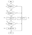
次に、ステップS10における第1の酸化触媒22が異常であるか否かの判定制御の制御手順を、図4を用いて説明する。なお、本ルーチンは、本発明の触媒機能低下判定手段に該当する。
本ルーチンは、強制再生による未燃燃料の供給が開始してから所定時間t2経過後に実行を開始する。所定時間t2は、未燃燃料の供給が開始されてから、未燃燃料の燃焼により、DPF24から流出する排気の温度Tfcが十分に上昇するような時間に適宜設定すればよい。
Next, a control procedure for determining whether or not the
This routine starts execution after a predetermined time t2 has elapsed since the supply of unburned fuel by forced regeneration started. The predetermined time t2 may be appropriately set to a time such that the temperature Tfc of the exhaust gas flowing out from the
ステップS52では、第1の温度センサ24により検出された排気温度Tfaが所定温度T3より高いか否かを判別する。排気温度Tfaが所定温度T3より高い場合は、ステップS54に進む。所定温度T3は、第1の酸化触媒22において酸化機能が確保される下限温度に設定すればよい。
ステップS54では、第2の温度センサにより検出された排気温度Tfbが所定温度T4より低いか否かを判別する。排気温度Tfbが所定温度T4より低い場合は、ステップS56に進む。所定温度T4は、第1の酸化触媒22に所定温度T3の排気が流入し、かつ強制再生により未燃燃料が所定時間t2供給され、第1の酸化触媒22にて未燃燃料が正常に燃焼された場合の第1の酸化触媒22通過後の排気温度をあらかじめ確認しておき、その下限値に設定すればよい。
In step S52, it is determined whether or not the exhaust temperature Tfa detected by the
In step S54, it is determined whether or not the exhaust temperature Tfb detected by the second temperature sensor is lower than a predetermined temperature T4. If the exhaust temperature Tfb is lower than the predetermined temperature T4, the process proceeds to step S56. At the predetermined temperature T4, the exhaust gas at the predetermined temperature T3 flows into the
ステップS56では、タイマをカウントさせる。このタイマは、排気温度Tfaが所定温度T3より高く、かつ排気温度Tfbが所定温度T4より低いと判定されてからの経過時間Tbをカウントする。そしてステップS58に進む。
ステップS58では、タイマによりカウントされている経過時間Tbが所定時間t3以上であるか否かを判別する。経過時間tbが所定時間t3以上である場合はステップS60に進む。経過時間tbが所定時間t3未満である場合は本ルーチンを終了する。なお、所定時間t3は、排気の温度変動により異常判定が頻発しないように適宜設定すればよい。
In step S56, a timer is counted. This timer counts an elapsed time Tb after it is determined that the exhaust temperature Tfa is higher than the predetermined temperature T3 and the exhaust temperature Tfb is lower than the predetermined temperature T4. Then, the process proceeds to step S58.
In step S58, it is determined whether or not the elapsed time Tb counted by the timer is equal to or longer than a predetermined time t3. If the elapsed time tb is equal to or longer than the predetermined time t3, the process proceeds to step S60. When the elapsed time tb is less than the predetermined time t3, this routine is finished. The predetermined time t3 may be set as appropriate so that abnormality determination does not occur frequently due to exhaust gas temperature fluctuations.
ステップS60では、第1の酸化触媒22が異常であると判定し、その結果を記憶装置に記憶する。そして、本ルーチンを終了する。
一方、上記ステップS52の判別により排気温度Tfaが所定温度T3以下であると判定された場合、ステップS54の判別により排気温度Tfbが所定温度T4以上であると判定された場合はステップS80に進む。
In step S60, it is determined that the
On the other hand, if it is determined in step S52 that the exhaust temperature Tfa is equal to or lower than the predetermined temperature T3, or if it is determined in step S54 that the exhaust temperature Tfb is equal to or higher than the predetermined temperature T4, the process proceeds to step S80.
ステップS80では、ステップS56においてカウントしたタイマ(排気温度Tfaが所定温度T3より高く、かつ排気温度Tfbが所定温度T4より低いと判定されてからの経過時間Tb)をクリアする。そして、本ルーチンを終了する。
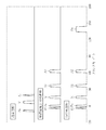
図5は、第1の酸化触媒22が異常時、即ち、酸化機能が低下しているときの排気温度の推移を示すグラフである。
In step S80, the timer counted in step S56 (elapsed time Tb after it is determined that the exhaust temperature Tfa is higher than the predetermined temperature T3 and the exhaust temperature Tfb is lower than the predetermined temperature T4) is cleared. Then, this routine ends.
FIG. 5 is a graph showing the transition of the exhaust temperature when the
第1の酸化触媒22が異常であるときは、図5に示すように、未燃燃料を供給して所定時間t2が経過しても、第1の酸化触媒22にて未燃燃料が燃焼しないことから、第1の酸化触媒22通過後の排気温度Tfbがほとんど上昇しない。そして、第2の酸化触媒23またはDPF21において未燃燃料が燃焼することから、DPF21通過後の排気温度Tfcは上昇する。これに対し、第1の酸化触媒22が正常であるときは、第1の酸化触媒22にて未燃燃料が燃焼することから、未燃燃料を供給して所定時間t2経過後には、第1の酸化触媒22通過後の排気温度Tfbが上昇する。そして、これに伴い、DPF21通過後の排気温度Tfcも上昇するが、第1の酸化触媒22にてほとんどの未燃燃料が燃焼することから、排気温度Tfbと排気温度Tfcとの差は少ない。したがって、第1の酸化触媒22に流入する排気の温度Tfaと第1の酸化触媒22から流出する排気の温度Tfbとの差が少ない場合には第1の酸化触媒22が異常であると判別することができる。また、第1の酸化触媒22から流出する排気の温度TfbとDPF21から流出する排気の温度Tfcとの差が大きい場合にも第1の酸化触媒22が異常であると判別することができる。
When the
以上のように、本実施形態では、排気温度に基づいて第1の酸化触媒22が異常であるか否かを判別し、異常であるときには、強制再生時における未燃燃料の供給の前に、排気温度を上昇させる。一方、正常であるときには、排気の温度を所定温度以上とする制御を所定時間実施し、強制再生における未燃燃料の供給を許可する。これにより、第1の酸化触媒22に付着した未燃燃料とPMとの混合物が燃焼される。したがって、第1の酸化触媒22に付着した未燃燃料とPMとの混合物が除去されることとなり、第1の酸化触媒22の酸化機能が回復される。更に、第1の酸化触媒22における酸化機能が確保されてから強制再生が可能となるので、余剰の未燃燃料がDPF21に流入することが抑制され、燃料の無駄な消費が抑制される。
As described above, in the present embodiment, it is determined whether or not the
なお、本実施形態では、第2の温度センサ25を第1の酸化触媒22と第2の酸化触媒23との間に設けているが、第2の酸化触媒23とDPF21との間に設けてもよい。このように配置すれば、第1の酸化触媒22及び第2の酸化触媒23における酸化機能を確保することができる。
In the present embodiment, the
1 エンジン
4 燃料噴射ノズル
21 DPF
27 差圧センサ
17 エアフローセンサ
22 第1の酸化触媒
23 第2の酸化触媒
24 第1の温度センサ
25 第2の温度センサ
26 第3の温度センサ
30 ECU
1 Engine 4
27
Claims (6)
前記フィルタの上流側の排気通路に設けられた酸化触媒と、
前記酸化触媒に未燃燃料を供給して酸化させ、前記酸化触媒の下流側の排気温度を上昇させることにより、前記フィルタに捕集されたパティキュレートを燃焼除去する強制再生手段と、
前記強制再生手段により未燃燃料の供給が開始されてから、通常時に前記強制再生手段から未燃燃料の供給が開始され前記フィルタから流出する排気の温度が十分上昇するまでの期間である所定時間経過後に前記酸化触媒の酸化機能の低下を判定する触媒機能低下判定手段と、
前記触媒機能低下判定手段により前記酸化触媒における酸化機能の低下が判定されたときに、前記酸化触媒に流入する排気の温度を上昇させる排気温度上昇制御手段と、
を含んで構成されることを特徴とする内燃機関の排気浄化装置。 A filter provided in an exhaust passage of the internal combustion engine for collecting particulates in the exhaust;
An oxidation catalyst provided in an exhaust passage upstream of the filter;
Forcibly regenerating means for burning and removing particulates collected in the filter by supplying unburned fuel to the oxidation catalyst to oxidize it, and raising the exhaust temperature downstream of the oxidation catalyst;
A predetermined time period from when the supply of unburned fuel is started by the forced regeneration means until the temperature of the exhaust gas flowing out from the filter is sufficiently increased after the supply of unburned fuel is started from the forced regeneration means at a normal time Catalyst function lowering determination means for determining a decrease in the oxidation function of the oxidation catalyst after elapse of time;
Exhaust temperature increase control means for increasing the temperature of the exhaust gas flowing into the oxidation catalyst when the catalyst function decrease determination means determines that the oxidation function of the oxidation catalyst is reduced;
An exhaust emission control device for an internal combustion engine, comprising:
Priority Applications (1)
| Application Number | Priority Date | Filing Date | Title |
|---|---|---|---|
| JP2006316902A JP4935983B2 (en) | 2006-11-24 | 2006-11-24 | Exhaust gas purification device for internal combustion engine |
Applications Claiming Priority (1)
| Application Number | Priority Date | Filing Date | Title |
|---|---|---|---|
| JP2006316902A JP4935983B2 (en) | 2006-11-24 | 2006-11-24 | Exhaust gas purification device for internal combustion engine |
Publications (2)
| Publication Number | Publication Date |
|---|---|
| JP2008128170A JP2008128170A (en) | 2008-06-05 |
| JP4935983B2 true JP4935983B2 (en) | 2012-05-23 |
Family
ID=39554256
Family Applications (1)
| Application Number | Title | Priority Date | Filing Date |
|---|---|---|---|
| JP2006316902A Active JP4935983B2 (en) | 2006-11-24 | 2006-11-24 | Exhaust gas purification device for internal combustion engine |
Country Status (1)
| Country | Link |
|---|---|
| JP (1) | JP4935983B2 (en) |
Families Citing this family (11)
| Publication number | Priority date | Publication date | Assignee | Title |
|---|---|---|---|---|
| JP5277891B2 (en) * | 2008-11-17 | 2013-08-28 | 三菱自動車工業株式会社 | Exhaust purification device |
| US8806928B2 (en) | 2010-04-30 | 2014-08-19 | Toyota Jidosha Kabushiki Kaisha | Catalyst deterioration detection apparatus and catalyst deterioration detection method for internal combustion engine |
| JP6011224B2 (en) * | 2012-10-09 | 2016-10-19 | いすゞ自動車株式会社 | Exhaust gas purification system and exhaust gas purification method |
| JP5959465B2 (en) * | 2013-03-29 | 2016-08-02 | 株式会社クボタ | Engine exhaust treatment equipment |
| JP5959464B2 (en) * | 2013-03-29 | 2016-08-02 | 株式会社クボタ | Engine exhaust treatment equipment |
| JP5905427B2 (en) * | 2013-09-27 | 2016-04-20 | 三菱重工業株式会社 | DPF regeneration control device |
| EP3184769B1 (en) * | 2015-12-25 | 2018-07-18 | Kubota Corporation | Exhaust apparatus for diesel engine |
| JP6963968B2 (en) * | 2017-10-31 | 2021-11-10 | 三菱重工エンジン&ターボチャージャ株式会社 | Vehicles, cargo handling vehicles, and exhaust gas treatment systems |
| JP7024392B2 (en) * | 2017-12-25 | 2022-02-24 | いすゞ自動車株式会社 | Exhaust aftertreatment device |
| JP7135612B2 (en) * | 2018-09-05 | 2022-09-13 | いすゞ自動車株式会社 | Exhaust purification device and exhaust purification method |
| JP7232167B2 (en) * | 2019-10-28 | 2023-03-02 | 株式会社クボタ | diesel engine |
Family Cites Families (3)
| Publication number | Priority date | Publication date | Assignee | Title |
|---|---|---|---|---|
| JP3799758B2 (en) * | 1997-08-05 | 2006-07-19 | トヨタ自動車株式会社 | Catalyst regeneration device for internal combustion engine |
| JP2005120986A (en) * | 2003-10-20 | 2005-05-12 | Toyota Motor Corp | Exhaust emission control system for internal combustion engine |
| JP4211611B2 (en) * | 2004-01-14 | 2009-01-21 | トヨタ自動車株式会社 | Exhaust gas purification device for internal combustion engine |
-
2006
- 2006-11-24 JP JP2006316902A patent/JP4935983B2/en active Active
Also Published As
| Publication number | Publication date |
|---|---|
| JP2008128170A (en) | 2008-06-05 |
Similar Documents
| Publication | Publication Date | Title |
|---|---|---|
| JP4935983B2 (en) | Exhaust gas purification device for internal combustion engine | |
| JP4673226B2 (en) | Exhaust gas purification method and exhaust gas purification system | |
| JP3933172B2 (en) | Exhaust gas purification system control method and exhaust gas purification system | |
| US6622480B2 (en) | Diesel particulate filter unit and regeneration control method of the same | |
| JP4100451B1 (en) | Exhaust gas purification method and exhaust gas purification system | |
| JP3979437B1 (en) | Exhaust gas purification system control method and exhaust gas purification system | |
| JP3956992B1 (en) | Exhaust gas purification method and exhaust gas purification system | |
| JP2009138704A (en) | Exhaust emission aftertreatment device | |
| JP2002371827A (en) | Exhaust emission control device for engine | |
| JP2008274835A (en) | Deterioration diagnosis device for oxidation catalyst | |
| JP4363289B2 (en) | Exhaust gas purification device for internal combustion engine | |
| JP4174685B1 (en) | Exhaust gas purification device for internal combustion engine | |
| JP5251711B2 (en) | Exhaust gas purification device for internal combustion engine | |
| JP2005282477A (en) | Method for controlling exhaust emission control system and exhaust emission control system | |
| JP2008121557A (en) | Exhaust emission control device of internal combustion engine | |
| JP4636278B2 (en) | Exhaust gas purification device for internal combustion engine | |
| JP2010249076A (en) | Exhaust emission control device of internal combustion engine | |
| JP5569690B2 (en) | Exhaust gas purification device for internal combustion engine | |
| JP2009299617A (en) | Exhaust emission control device for internal combustion engine | |
| JP2008138537A (en) | Exhaust emission control device for internal combustion engine | |
| JP4052268B2 (en) | Exhaust gas purification device for internal combustion engine | |
| JP4780335B2 (en) | Exhaust gas purification device for internal combustion engine | |
| JP4697474B2 (en) | Exhaust gas purification device for internal combustion engine | |
| JP2010133307A (en) | Exhaust emission control device for engine | |
| JP2006274978A (en) | Exhaust emission control device of internal combustion engine |
Legal Events
| Date | Code | Title | Description |
|---|---|---|---|
| A621 | Written request for application examination |
Free format text: JAPANESE INTERMEDIATE CODE: A621 Effective date: 20090205 |
|
| A131 | Notification of reasons for refusal |
Free format text: JAPANESE INTERMEDIATE CODE: A131 Effective date: 20101013 |
|
| A977 | Report on retrieval |
Free format text: JAPANESE INTERMEDIATE CODE: A971007 Effective date: 20101014 |
|
| A521 | Written amendment |
Free format text: JAPANESE INTERMEDIATE CODE: A523 Effective date: 20101203 |
|
| A131 | Notification of reasons for refusal |
Free format text: JAPANESE INTERMEDIATE CODE: A131 Effective date: 20110427 |
|
| A521 | Written amendment |
Free format text: JAPANESE INTERMEDIATE CODE: A523 Effective date: 20110620 |
|
| TRDD | Decision of grant or rejection written | ||
| A01 | Written decision to grant a patent or to grant a registration (utility model) |
Free format text: JAPANESE INTERMEDIATE CODE: A01 Effective date: 20120125 |
|
| A01 | Written decision to grant a patent or to grant a registration (utility model) |
Free format text: JAPANESE INTERMEDIATE CODE: A01 |
|
| A61 | First payment of annual fees (during grant procedure) |
Free format text: JAPANESE INTERMEDIATE CODE: A61 Effective date: 20120207 |
|
| FPAY | Renewal fee payment (event date is renewal date of database) |
Free format text: PAYMENT UNTIL: 20150302 Year of fee payment: 3 |
|
| R151 | Written notification of patent or utility model registration |
Ref document number: 4935983 Country of ref document: JP Free format text: JAPANESE INTERMEDIATE CODE: R151 |
|
| FPAY | Renewal fee payment (event date is renewal date of database) |
Free format text: PAYMENT UNTIL: 20150302 Year of fee payment: 3 |
|
| S531 | Written request for registration of change of domicile |
Free format text: JAPANESE INTERMEDIATE CODE: R313531 |
|
| R350 | Written notification of registration of transfer |
Free format text: JAPANESE INTERMEDIATE CODE: R350 |