JP4935775B2 - Control device for internal combustion engine - Google Patents
Control device for internal combustion engine Download PDFInfo
- Publication number
- JP4935775B2 JP4935775B2 JP2008187186A JP2008187186A JP4935775B2 JP 4935775 B2 JP4935775 B2 JP 4935775B2 JP 2008187186 A JP2008187186 A JP 2008187186A JP 2008187186 A JP2008187186 A JP 2008187186A JP 4935775 B2 JP4935775 B2 JP 4935775B2
- Authority
- JP
- Japan
- Prior art keywords
- control
- engine
- vvt
- amount
- idle
- Prior art date
- Legal status (The legal status is an assumption and is not a legal conclusion. Google has not performed a legal analysis and makes no representation as to the accuracy of the status listed.)
- Active
Links
Images


Classifications
-
- Y—GENERAL TAGGING OF NEW TECHNOLOGICAL DEVELOPMENTS; GENERAL TAGGING OF CROSS-SECTIONAL TECHNOLOGIES SPANNING OVER SEVERAL SECTIONS OF THE IPC; TECHNICAL SUBJECTS COVERED BY FORMER USPC CROSS-REFERENCE ART COLLECTIONS [XRACs] AND DIGESTS
- Y02—TECHNOLOGIES OR APPLICATIONS FOR MITIGATION OR ADAPTATION AGAINST CLIMATE CHANGE
- Y02T—CLIMATE CHANGE MITIGATION TECHNOLOGIES RELATED TO TRANSPORTATION
- Y02T10/00—Road transport of goods or passengers
- Y02T10/10—Internal combustion engine [ICE] based vehicles
- Y02T10/12—Improving ICE efficiencies
-
- Y—GENERAL TAGGING OF NEW TECHNOLOGICAL DEVELOPMENTS; GENERAL TAGGING OF CROSS-SECTIONAL TECHNOLOGIES SPANNING OVER SEVERAL SECTIONS OF THE IPC; TECHNICAL SUBJECTS COVERED BY FORMER USPC CROSS-REFERENCE ART COLLECTIONS [XRACs] AND DIGESTS
- Y02—TECHNOLOGIES OR APPLICATIONS FOR MITIGATION OR ADAPTATION AGAINST CLIMATE CHANGE
- Y02T—CLIMATE CHANGE MITIGATION TECHNOLOGIES RELATED TO TRANSPORTATION
- Y02T10/00—Road transport of goods or passengers
- Y02T10/10—Internal combustion engine [ICE] based vehicles
- Y02T10/40—Engine management systems
Description
本発明は、機関バルブの開閉タイミングを機関運転状態に応じて制御する可変バルブタイミング機構が搭載された内燃機関の制御装置に関する。 The present invention relates to a control device for an internal combustion engine equipped with a variable valve timing mechanism that controls opening / closing timing of an engine valve according to an engine operating state.
車両等に搭載される内燃機関(以下、エンジンとも言う)においては、クランクシャフトの回転がタイミングチェーン等を介してカムシャフトに伝達される。エンジンの機関バルブ(吸気バルブ・排気バルブ)は、カムシャフトのカムにより周期的に押し下げられて往復動し、吸気通路・排気通路を開閉する。このタイプのエンジンでは、クランクシャフトに対するカムシャフトの回転位相は常に一定である。これに対し、近年では、エンジンに可変バルブタイミング(VVT:Variable Valve Timing)機構を搭載している(例えば、特許文献1、2参照)。可変バルブタイミング機構は、エンジンの出力向上、燃費向上、排気エミッション低減などを目的として、クランクシャフトに対するカムシャフトの回転位相を変化させ、機関バルブの開閉タイミングを変更する機構である。 In an internal combustion engine (hereinafter also referred to as an engine) mounted on a vehicle or the like, rotation of a crankshaft is transmitted to a camshaft via a timing chain or the like. The engine valve (intake valve / exhaust valve) of the engine is periodically pushed down by the cam of the camshaft and reciprocates to open and close the intake passage and the exhaust passage. In this type of engine, the rotational phase of the camshaft relative to the crankshaft is always constant. On the other hand, in recent years, a variable valve timing (VVT: Variable Valve Timing) mechanism is mounted on the engine (see, for example, Patent Documents 1 and 2). The variable valve timing mechanism is a mechanism for changing the opening / closing timing of the engine valve by changing the rotational phase of the camshaft relative to the crankshaft for the purpose of improving engine output, improving fuel consumption, and reducing exhaust emissions.
可変バルブタイミング機構(以下、VVTとも言う)としては、例えばヘリカルスプライン式とベーン式の機構とがある。これらのうち、ベーン式VVTは、例えば、内周面に凹部が形成されたハウジングと、そのハウジングの凹部を2つの油圧室(遅角側油圧室、進角側油圧室)に区画するベーンを有する内部ロータとを備え、前記ハウジングをクランクシャフトに連結し、内部ロータをカムシャフトに連結した状態で、前記遅角側油圧室及び進角側油圧室に供給する油圧をオイルコントロールバルブ(OCV)によって制御することにより、クランクシャフトとカムシャフトとの回転位相をずらして機関バルブの開閉タイミングを連続的に変化させる構造となっている。 Examples of the variable valve timing mechanism (hereinafter also referred to as VVT) include a helical spline type and a vane type mechanism. Among these, the vane type VVT includes, for example, a housing in which a recess is formed on the inner peripheral surface, and a vane that divides the recess of the housing into two hydraulic chambers (retarding-side hydraulic chamber, advance-side hydraulic chamber). An oil control valve (OCV) for supplying hydraulic pressure to the retard side hydraulic chamber and the advance side hydraulic chamber in a state where the housing is connected to the crankshaft and the internal rotor is connected to the camshaft. By controlling by the above, the rotational phase of the crankshaft and the camshaft is shifted to continuously change the opening / closing timing of the engine valve.
また、車両に搭載されるエンジンにおいては、アイドル運転時の実際のアイドル回転数が目標アイドル回転数に一致するように、スロットルバルブの開度(スロットル開度)を調整してエンジンへの吸入空気量をフィードバック制御するアイドル回転数制御(ISC:Idle Speed Control)が実行されている。 Also, in an engine mounted on a vehicle, the throttle valve opening (throttle opening) is adjusted so that the actual idling speed during idling matches the target idling speed, and the intake air to the engine is adjusted. Idle speed control (ISC: Idle Speed Control) for feedback control of the amount is executed.
さらに、車両に搭載されるエンジンにおいては、燃焼によって得られる出力を効率よく得ること、及び、排気ガス浄化性能や燃費性能を良好とすることを目的として点火時期制御が行われている。このようなエンジンの点火時期制御では、エンジン回転数及び負荷などのエンジンの運転状態に基づいて点火時期を求めている。 Furthermore, in an engine mounted on a vehicle, ignition timing control is performed for the purpose of efficiently obtaining an output obtained by combustion and improving exhaust gas purification performance and fuel consumption performance. In such engine ignition timing control, the ignition timing is obtained based on the engine operating state such as the engine speed and load.
一方、車両に搭載されるエンジンにおいては、例えば、スロットル開度が全閉状態(アイドルオン)で、かつ、エンジン回転数が所定値(カット回転数)以上であるという条件が成立したときに、フューエルカット(以下、F/Cとも言う)を実行している。 On the other hand, in the engine mounted on the vehicle, for example, when the condition that the throttle opening is in a fully closed state (idle on) and the engine speed is a predetermined value (cut speed) or more is satisfied, A fuel cut (hereinafter also referred to as F / C) is performed.
このようなアイドルオンF/C制御においては、通常、カット回転数を、アイドルオンで定常走行が可能なエンジン回転数よりも高く設定することで、F/Cハンチングを防止している。しかし、燃費・触媒臭等の要求に応えるにはカット回転数を低めに設定することが必要である。このような点から、従来制御では、エンジン水温に応じたカット回転数の可変設定(ファーストアイドル変化対応)や、エアコンON/OFFやフレックスロックアップ有無等の切り分け設定(補機、ECT(Electronic Controlled Automatic Transmission)の負荷変化対応)などを行っている。 In such idle-on F / C control, F / C hunting is usually prevented by setting the cut rotational speed higher than the engine rotational speed at which steady running is possible with idle-on. However, it is necessary to set the cut rotational speed to be lower in order to meet the demands for fuel consumption, catalyst odor, and the like. From this point, in the conventional control, the variable setting of the cutting speed according to the engine water temperature (corresponding to the first idle change) and the separation setting such as air conditioner ON / OFF and flex lockup (auxiliary machine, ECT (Electronic Controlled) (Automatic Transmission)).
なお、F/Cハンチングに関する技術として下記の特許文献3に記載のものがある。この特許文献3に記載の技術では、アイドル時のバイパス空気量の大小に応じて燃料カット復帰回転数を補正することで、F/Cハンチングを抑制している。
ところで、VVTが搭載されたエンジンにおいては、冷間時(例えば冷間ファーストアイドル時)のエミッション向上のためにVVT制御(例えば排気側VVTの制御)を実行することが検討されている。しかし、VVT制御を実行するとトルクが変化するため、例えば上記したアイドルオンF/C制御を実施する場合、F/Cハンチングが発生する可能性がある。この点について図14を参照して説明する。 By the way, in an engine equipped with a VVT, it has been studied to execute VVT control (for example, control of the exhaust side VVT) in order to improve emissions during cold (for example, during cold first idling). However, since the torque changes when the VVT control is executed, F / C hunting may occur, for example, when the above-described idle-on F / C control is performed. This point will be described with reference to FIG.
まず、図14において、例えばVVTが非制御状態(アクセルペダルが軽く踏まれた状態)であり、トルクTQ1で走行している時(b1)はスロットル開度TAは開(アイドルオフ)である。このような状況からVVT制御の実行条件が成立してVVT制御が実行されると、スロットル開度TAが同じでも、トルクがTQ2に増加するためエンジンの動作点はa2となる。こうした状況になると、(A)『ドライバは定常走行を保つ(トルクTQ1を維持する)ように、アクセル戻し操作を行うのでスロットル開度TAが全閉(a1)となってアイドルオンとなる。ここで、ある定常走行時のつりあいトルクがTQ1であるとすると、VVT非制御時ではスロットル開度TAがb2となるが、VVT制御時ではスロットル開度TAがb2となるので、TQ2までトルクがでるためドライバは足を戻してトルクをTQ1に近づけようとする。VVT制御時の全閉トルクがTQ3であるとすると、TQ3>TQ1の関係にあるときは、走行抵抗がつりあうまでエンジン回転数NEが上昇する(なお、TQ3=TQ1ならば、エンジン回転数NEは維持される)。このとき、エンジン回転数NEがカット回転数に達する』とF/Cが実行される。F/Cが実行されると、エンジン回転数NE及び車速が低下し、F/C解除条件(NE<復帰回転数)が成立した時点でF/C復帰(F/C解除)となる。この後、ドライバが定常走行(車速)を保つようにアクセル操作を行うと、上記した(A)の過程のあと、再度F/C条件が成立してF/Cが実行される。このようにしてF/C実行とF/C解除とが交互に繰り返される(F/Cハンチング)。 First, in FIG. 14, for example, when the VVT is in an uncontrolled state (a state where the accelerator pedal is lightly depressed) and the vehicle is running at the torque TQ1 (b1), the throttle opening degree TA is open (idle off). If the execution condition of the VVT control is established from such a situation and the VVT control is executed, the engine operating point becomes a2 because the torque increases to TQ2 even if the throttle opening degree TA is the same. In such a situation, (A) “The driver performs the accelerator return operation so as to keep steady running (maintain torque TQ1), so that the throttle opening degree TA is fully closed (a1) and the engine is idle-on. Here, assuming that the balancing torque during a certain steady running is TQ1, the throttle opening TA is b2 when VVT is not controlled, but the throttle opening TA is b2 when VVT is controlled, so the torque is up to TQ2. Therefore, the driver tries to return the foot to bring the torque closer to TQ1. Assuming that the fully closed torque at the time of VVT control is TQ3, when TQ3> TQ1, the engine speed NE increases until the running resistance is balanced (If TQ3 = TQ1, the engine speed NE is Maintained). At this time, when the engine speed NE reaches the cut speed, "F / C is executed. When the F / C is executed, the engine speed NE and the vehicle speed are reduced, and the F / C return (F / C release) is established when the F / C release condition (NE <return speed) is satisfied. Thereafter, when the driver performs an accelerator operation so as to maintain steady running (vehicle speed), the F / C condition is again established and the F / C is executed after the above-described process (A). In this way, F / C execution and F / C release are alternately repeated (F / C hunting).
このようなF/Cハンチングを防止するには、アイドルオンF/C制御の実施条件であるカット回転数を高く設定することが考えられるが、カット回転数を一律に上げてしまうと、VVT制御を実行しないときに燃費が悪化し、触媒臭が発生する可能性がある。 In order to prevent such F / C hunting, it is conceivable to set the cut rotation speed, which is the execution condition of the idle-on F / C control, to be high. However, if the cut rotation speed is increased uniformly, VVT control is performed. The fuel consumption may deteriorate and the catalyst odor may be generated.
本発明はそのような実情を考慮してなされたもので、機関バルブの開閉タイミングを機関運転状態に応じて制御する可変バルブタイミング機構が搭載された内燃機関の制御装置において、可変バルブタイミング機構の制御を実行したときのトルク変化による影響(例えばF/Cハンチング)を抑制することが可能な制御の実現を目的とする。 The present invention has been made in view of such circumstances, and in an internal combustion engine control device equipped with a variable valve timing mechanism for controlling the opening / closing timing of an engine valve in accordance with the engine operating state, the variable valve timing mechanism is It aims at realization of control which can control influence (for example, F / C hunting) by torque change at the time of performing control.
本発明は、燃焼室内に連通する吸気通路及び排気通路と、前記燃焼室と吸気通路との間を選択的に開閉する吸気バルブと、前記燃焼室と排気通路との間を選択的に開閉する排気バルブと、前記吸気バルブ及び排気バルブのうちの少なくとも一方のバルブの開閉タイミングを当該内燃機関の運転状態に応じて調整する可変バルブタイミング機構とを備えた内燃機関の制御装置を前提としており、このような内燃機関の制御装置において、アイドルオンのときに機関回転数に基づいてフューエルカットを実行するアイドルオンフューエルカット制御手段を備えており、前記アイドルオンフューエルカットのカット条件を、前記アイドルオンフューエルカットの実行条件であるカット回転数、及び、前記アイドルオンフューエルカットからの復帰条件である復帰回転数とする。そして、前記可変バルブタイミング機構の制御量が所定の判定閾値以上である場合には、下限ガード値を用いて前記復帰回転数に対して下限ガード処理を行うことにより、前記可変バルブタイミング機構の制御時の前記カット回転数及び前記復帰回転数を当該可変バルブタイミング機構の非制御時に対して高い側に設定することを特徴としている。なお、以下の説明では、可変バルブタイミング機構の制御のことをVVT制御と言い、可変バルブタイミング機構の非制御のことをVVT非制御と言う場合もある。 The present invention selectively opens and closes between an intake passage and an exhaust passage communicating with a combustion chamber, an intake valve that selectively opens and closes between the combustion chamber and the intake passage, and between the combustion chamber and the exhaust passage. Assuming an internal combustion engine control device comprising an exhaust valve and a variable valve timing mechanism that adjusts the opening / closing timing of at least one of the intake valve and the exhaust valve according to the operating state of the internal combustion engine, Such a control device for an internal combustion engine includes idle-on-fuel cut control means for executing fuel cut based on the engine speed when idling is on. The cutting speed that is the execution condition of the fuel cut, and the return condition from the idle on fuel cut To return speed and is. When the control amount of the variable valve timing mechanism is equal to or greater than a predetermined determination threshold, the lower limit guard value is used to perform the lower limit guard process on the return rotational speed, thereby controlling the variable valve timing mechanism. The cut rotation speed and the return rotation speed at the time are set to a higher side than when the variable valve timing mechanism is not controlled . In the following description, the control of the variable valve timing mechanism may be referred to as VVT control, and the non-control of the variable valve timing mechanism may be referred to as VVT non-control.
本発明によれば、例えば冷間時にVVT制御が実行されても、そのVVT制御による影響(例えばF/Cハンチング)を抑制することができる。この点について説明する。 According to the present invention, for example, even if VVT control is executed at the time of cold can win influence of the VVT control (e.g. F / C hunting) depression. This point will be described.
まず、アイドルオンのときに機関回転数に基づいてF/Cを実行するアイドルオンF/C制御手段を備えている場合、アイドルオンF/Cのカット条件を、VVT制御の制御量に応じて変更するという構成を採用する。なお、本発明で言う「カット条件」とは、アイドルオンF/Cを実行条件であるカット回転数、及び、アイドルオンF/Cからの復帰条件(解除条件)である復帰回転数である。これらカット回転数と復帰回転数との関係は、例えば[カット回転数=復帰回転数+α(ヒステリシス)]である。 First, when an idle-on F / C control means for executing F / C based on the engine speed when idling is on is provided, the idling-on F / C cut condition is set according to the control amount of the VVT control. Use a configuration that changes. The “cut condition” referred to in the present invention is a cut rotation speed that is an execution condition of idle-on F / C and a return rotation speed that is a return condition (release condition) from idle-on F / C. The relationship between the cut rotational speed and the return rotational speed is, for example, [cut rotational speed = return rotational speed + α (hysteresis)].
そして、この発明においては、VVTの制御量に応じてアイドルトルクが変化し、これに伴ってアイドルオン走行可能なエンジン回転数が変化する点を考慮して、例えばVVT制御量が一定以上変化したときにアイドルオンF/Cのカット条件を変更する。具体的には、例えば、上記した復帰回転数に下限ガードを設けてカット回転数を高い側に設定することによって、F/Cハンチングの発生を抑制することができる。これにより、例えば冷間時にVVT制御を実行することが可能になる。 In the present invention, in consideration of the fact that the idle torque changes in accordance with the control amount of VVT and the engine speed at which the engine can be idle-on changes accordingly, for example, the VVT control amount changes more than a certain value. Sometimes the idle-on F / C cut condition is changed. Specifically, for example, by providing a lower limit guard for the above-described return rotational speed and setting the cut rotational speed to the higher side, occurrence of F / C hunting can be suppressed. Thereby, it becomes possible to perform VVT control, for example at the time of cold.
この発明において、VVT制御量に応じて変化するトルク変化量を求め、そのトルク変化量に基づいてカット条件を可変に設定する。具体的には、トルク変化量に基づいて上記F/C復帰回転数(カット回転数)の下限ガードを可変に設定するという構成を採用すれば、F/Cハンチングの発生をより効果的に抑制することができる。 In the present invention, a torque change amount that changes in accordance with the VVT control amount is obtained, and the cutting condition is variably set based on the torque change amount. Specifically, if a configuration is adopted in which the lower limit guard of the F / C return rotation speed (cut rotation speed) is variably set based on the amount of torque change, the occurrence of F / C hunting can be more effectively suppressed. can do.
本発明によれば、例えば、冷間時にVVT制御を実行しても、F/Cハンチングの発生を抑制することができるので、排気エミッションの向上とドライバビリティの向上を図ることができる。 According to the present invention, for example, even when the VVT control is executed in the cold state, the occurrence of F / C hunting can be suppressed, so that it is possible to improve exhaust emission and drivability.
以下、本発明の実施形態を図面に基づいて説明する。
まず、本発明を適用するエンジン(内燃機関)について説明する。
Hereinafter, embodiments of the present invention will be described with reference to the drawings.
First, an engine (internal combustion engine) to which the present invention is applied will be described.
−エンジン−
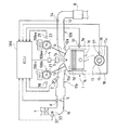
図1は本発明を適用するエンジンの概略構成を示す図である。なお、図1にはエンジンの1気筒の構成のみを示している。
-Engine-
FIG. 1 is a diagram showing a schematic configuration of an engine to which the present invention is applied. FIG. 1 shows only the configuration of one cylinder of the engine.
エンジン1は、車両に搭載されるポート噴射型多気筒ガソリンエンジンであって、その各気筒を構成するシリンダブロック1a内には上下方向に往復動するピストン1cが設けられている。ピストン1cはコネクティングロッド16を介してクランクシャフト15に連結されており、ピストン1cの往復運動がコネクティングロッド16によってクランクシャフト15の回転へと変換される。エンジン1のクランクシャフト15は自動変速機等のトランスミッション(図示せず)に連結される。
The engine 1 is a port injection type multi-cylinder gasoline engine mounted on a vehicle, and a
クランクシャフト15にはシグナルロータ17が取り付けられている。シグナルロータ17の外周面には複数の突起(歯)17aが等角度ごとに設けられている。シグナルロータ17の側方近傍にはクランクポジションセンサ(エンジン回転数センサ)37が配置されている。クランクポジションセンサ37は、例えば電磁ピックアップであって、クラン
クシャフト15が回転する際にシグナルロータ17の突起17aに対応するパルス状の信号(出力パルス)を発生する。
A
エンジン1のシリンダブロック1aには冷却水温を検出する水温センサ31が配置されている。また、シリンダブロック1aの上端にはシリンダヘッド1bが設けられており、このシリンダヘッド1bとピストン1cとの間に燃焼室1dが形成されている。エンジン1の燃焼室1dには点火プラグ3が配置されている。点火プラグ3の点火タイミングはイグナイタ4によって調整される。
A
エンジン1のシリンダブロック1aの下部には、潤滑油を貯留するオイルパン18が設けられている。このオイルパン18に貯留された潤滑油は、エンジン1の運転時に、異物を除去するオイルストレーナ20(図3参照)を介してオイルポンプ19によって汲み上げられて、ピストン1c、クランクシャフト15、コネクティングロッド16などに供給され、各部の潤滑・冷却等に使用される。そして、このようにして供給された潤滑油は、エンジン1の各部の潤滑・冷却等のために使用された後、オイルパン18に戻され、再びオイルポンプ19によって汲み上げられるまでオイルパン18内に貯留される。
An
また、この例においては、オイルパン18に貯留された潤滑油を、後述する可変バルブタイミング機構(以下、VVTと言う)100in,100exの作動油にも利用している。なお、オイルポンプ19は、エンジン1のクランクシャフト15の回転によって駆動される機械式ポンプである。
In this example, the lubricating oil stored in the
エンジン1の燃焼室1dには吸気通路11と排気通路12とが接続されている。吸気通路11の一部は吸気ポート11a及び吸気マニホールド11bによって形成されている。また、排気通路12の一部は排気ポート12a及び排気マニホールド12bによって形成されている。
An
吸気通路11には、エアクリーナ7、熱線式のエアフロメータ32、吸気温センサ33(エアフロメータ32に内蔵)、エンジン1の吸入空気量を調整するための電子制御式のスロットルバルブ5などが配置されている。スロットルバルブ5はスロットルモータ6によって駆動される。スロットルバルブ5の開度(スロットル開度TA)はスロットル開度センサ36によって検出される。
An
スロットルバルブ5は、エンジン回転数NEと運転者のアクセルペダル踏み込み量(アクセル開度)等のエンジン1の運転状態に応じた最適な吸入空気量(目標吸気量)が得られるようにスロットル開度TAが制御される。具体的には、スロットル開度センサ36にて実際のスロットル開度TAを検出し、その実スロットル開度TAが、上記目標吸気量が得られるスロットル開度(目標スロットル開度)に一致するようにスロットルバルブ5のスロットルモータ6がフィードバック制御される。なお、このようなスロットルバルブ5の制御は後述するECU(Electronic Control Unit)300によって実行される。
The
一方、エンジン1の排気通路12には、排気ガス中の酸素濃度を検出するO2センサ34及び三元触媒8が配置されている。
On the other hand, an O 2 sensor 34 and a three-
吸気通路11と燃焼室1dとの間に吸気バルブ13が設けられており、この吸気バルブ13を開閉駆動することにより、吸気通路11と燃焼室1dとが連通または遮断される。また、排気通路12と燃焼室1dとの間に排気バルブ14が設けられており、この排気バルブ14を開閉駆動することにより、排気通路12と燃焼室1dとが連通または遮断される。これら吸気バルブ13及び排気バルブ14の開閉駆動は、クランクシャフト15の回転がタイミングチェーン等を介して伝達される吸気カムシャフト21及び排気カムシャフト22の各回転によって行われる。吸気カムシャフト21と排気カムシャフト22の各端部にはそれぞれ吸気側VVT100inと排気側VVT100exとが設けられている。これら吸気側VVT100in及び排気側VVT100exについては後述する。
An
また、吸気カムシャフト21及び排気カムシャフト22の近傍にはそれぞれカムポジションセンサ38,39が配置されている。各カムポジションセンサ38,39は、例えば電磁ピックアップであって、吸気カムシャフト21及び排気カムシャフト22に一体的に設けられたロータ外周面の1個の突起(図示せず)に対向するように配置されており、その各カムシャフト21,22が回転する際にパルス状の信号を出力する。なお、吸気カムシャフト21及び排気カムシャフト22は、クランクシャフト15の1/2の回転速度で回転するので、クランクシャフト15が720°回転するごとに各カムポジションセンサ38,39が1つのパルス状の信号を発生する。
Further,
そして、吸気通路11には燃料噴射用のインジェクタ(燃料噴射弁)2が配置されている。インジェクタ2には燃料タンクから燃料ポンプによって所定圧力の燃料が供給され、吸気通路11の吸気ポート11a内に燃料が噴射される。この噴射燃料は吸入空気と混合されて混合気となってエンジン1の燃焼室1dに導入される。燃焼室1dに導入された混合気(燃料+空気)は点火プラグ3にて点火されて燃焼・爆発する。この混合気の燃焼室1d内での燃焼・爆発によりピストン1cが往復運動してクランクシャフト15が回転する。
A fuel injection injector (fuel injection valve) 2 is disposed in the
以上のエンジン1の運転状態はECU300によって制御される。そして、このECU300により実行されるプログラムによって本発明の内燃機関の制御装置が実現される。
The operation state of the engine 1 is controlled by the
−VVT−
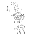
吸気側VVT100in及び排気側VVT100exは、図2及び図3に示すように、略中空円盤状のハウジング101と、このハウジング101内に回転自在に収容されたベーンロータ104とを備えている。ベーンロータ104には複数(この例では4枚)のベーン105が一体形成されている。ベーンロータ104はセンタボルト106によって吸気カムシャフト21(または排気カムシャフト22)に固定されており、吸気カムシャフト21(または排気カムシャフト22)と一体となって回転する。
-VVT-
As shown in FIGS. 2 and 3, the intake side VVT 100 in and the exhaust side VVT 100 ex include a substantially hollow disk-shaped
ハウジング101の前面側はフロントカバー107によって覆われている。これらハウジング101とフロントカバー107とはボルト108にてスプロケット109に固定されており、ハウジング101及びフロントカバー107はスプロケット109と一体となって回転する。スプロケット109は、タイミングチェーン110を介してクランクシャフト15に連結される。
The front side of the
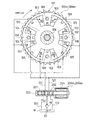
ハウジング101の内部には、ベーンロータ104のベーン105と同数の凸部102が形成されており、その各凸部102間に形成された凹部103内にベーンロータ104の各ベーン105が収容されている。各ベーン105の先端面は凹部103の内周面に摺動可能に接触している。ベーンロータ104は、作動油の圧力をベーン105で受けることによりハウジング101に対して相対回転する。この相対回転により、クランクシャフト15に対する吸気カムシャフト21(または排気カムシャフト22)の回転位相が変化する。
The same number of
ハウジング101の各凹部103には、ベーンロータ104のベーン105によって区画された2つの空間が形成されている。これら2つの空間のうち、ベーン105に対してカムシャフト回転方向(図3の矢印の方向)の後側の空間が進角側油圧室111を構成しており、カムシャフト回転方向の前側の空間が遅角側油圧室112を構成している。
In each
以上の構造のVVT100in,100exでは、進角側油圧室111内の油圧と遅角側油圧室112内の油圧によってベーンロータ104がハウジング101に対して相対回転する。すなわち、進角側油圧室111内の油圧を遅角側油圧室112内の油圧よりも高くすると、ベーンロータ104はハウジング101に対して吸気カムシャフト21(または排気カムシャフト22)の回転方向に相対回転する。このとき、吸気カムシャフト21(または排気カムシャフト22)の回転位相はクランクシャフト15の回転位相に対して進められる(進角)。これとは逆に、遅角側油圧室112内の油圧を進角側油圧室111の油圧よりも高くすると、ベーンロータ104はハウジング101に対して吸気カムシャフト21(または排気カムシャフト22)の回転方向と逆方向に相対回転され、吸気カムシャフト21(または排気カムシャフト22)の回転位相はクランクシャフト15の回転位相に対して遅らされる(遅角)。そして、このような回転位相の調整によって吸気バルブ13(または排気バルブ14)の開閉タイミングを可変とすることができる。
In the VVT 100 in and 100 ex having the above structure, the
次に、進角側油圧室111と遅角側油圧室112に供給する作動油の油圧を制御する油圧制御系の構成について図3を参照して説明する。
Next, the configuration of a hydraulic control system that controls the hydraulic pressure of the hydraulic oil supplied to the advance side
まず、吸気側VVT100in及び排気側VVT100exには、その各進角側油圧室111と遅角側油圧室112とに供給する作動油の油圧を制御するオイルコントロールバルブ(以下、OCVという)200in,200exが接続されている。
First, the intake-side VVT 100in and the exhaust-side VVT 100ex include oil control valves (hereinafter referred to as OCV) 200in, 200ex that control the hydraulic pressure of the hydraulic oil supplied to the advance-side
OCV200in,200exには、オイルポンプ19によってオイルパン18からオイルストレーナ20を介して汲み上げられた潤滑油(作動油)がオイル供給通路131を介して供給される。また、各OCV200in,200exには2つのオイル排出通路132,133が接続されている。OCV200in,200exは電磁駆動式の流量制御弁であり、ECU300によって制御される。
The OCV 200in, 200ex is supplied with lubricating oil (operating oil) pumped from the
OCV200in,200exは、4ポート弁であって、ケーシング201の内部に往復移動可能に配設されたスプール202と、スプール202に弾性力を付勢する圧縮コイルばね203と、電磁ソレノイド204とを備えており、電磁ソレノイド204に電圧が印加されたときにスプール202が吸引されるようになっている。電磁ソレノイド204に印加する電圧は、ECU300(図4参照)によってデューティ制御される。電磁ソレノイド204が発生する吸引力は印加電圧のデューティ比に応じて変化する。この電磁ソレノイド204が発生する吸引力と圧縮コイルばね203の付勢力との釣り合いによってスプール202の位置が決定される。
The OCV 200in, 200ex is a 4-port valve, and includes a
そして、スプール202が移動することによって、進角側通路121及び遅角側通路122と、オイル供給通路131及びオイル排出通路132,133との連通量が変化し、進角側通路121及び遅角側通路122に対して供給される作動油の量、あるいは、これら進角側通路121及び遅角側通路122から排出される作動油の量が変化する。
As the
例えば、吸気側のOCV200inは、電磁ソレノイド204に印加される電圧のデューティ比が大きいほど、進角側通路121に供給される作動油の供給量が多くなって吸気カムシャフト21の回転位相が進角される。一方、デューティ比が小さいほど、遅角側通路122に供給される作動油の供給量が多くなって吸気カムシャフト21の回転位相が遅角される。このようにして進角側油圧室111及び遅角側油圧室112内の油圧を調整することにより、ベーンロータ104の回転位相(クランクシャフト15に対する吸気カムシャフト21の回転位相)を調整することができ、これによって吸気バルブ13の開閉タイミングを最遅角位置から最進角位置までの範囲で任意に調整することができる。
For example, in the intake side OCV 200in, the larger the duty ratio of the voltage applied to the
なお、排気側のOCV200exについても、吸気側のOCV200inと同様にデューティ制御され、排気バルブ14の開閉タイミングを最進角位置から最遅角位置までの範囲で任意に調整することができる。ただし、遅角と進角との関係が吸気側のOCV200inの場合とは逆になる。
The exhaust-side OCV 200ex is also duty-controlled in the same manner as the intake-side OCV 200in, and the opening / closing timing of the
以上の吸気側VVT100in及び排気側VVT100exの作動(OCV200in,200exの制御)はECU300によって制御される。ECU300は、エンジン1の運転状態(例えばエンジン回転数・負荷)に基づいて、各VVT100in,100exに対しそれぞれ個別に設定されたマップを参照して、当該VVT100in,100exの作動を制御する。
The operation of the intake side VVT 100in and the exhaust side VVT 100ex (control of the OCV 200in, 200ex) is controlled by the
−ECU−
ECU300は、図4に示すように、CPU301、ROM302、RAM303及びバックアップRAM304などを備えている。ROM302は、各種制御プログラムや、それら各種制御プログラムを実行する際に参照されるマップ等が記憶されている。
-ECU-
The
CPU301は、ROM302に記憶された各種制御プログラムやマップに基づいて演算処理を実行する。また、RAM303はCPU301での演算結果や各センサから入力されたデータ等を一時的に記憶するメモリであり、バックアップRAM304はエンジン1の停止時にその保存すべきデータ等を記憶する不揮発性のメモリである。
The
これらCPU301、ROM302、RAM303、及び、バックアップRAM304はバス307を介して互いに接続されるとともに、入力インターフェース305及び出力インターフェース306と接続されている。
The
入力インターフェース305には、水温センサ31、エアフロメータ32、吸気温センサ33、O2センサ34、アクセル開度を検出するアクセル開度センサ35、スロットル開度センサ36、クランクポジションセンサ37、カムポジションセンサ38,39、及び、イグニッションスイッチ40などの各種センサ・スイッチが接続されている。
The
出力インターフェース306には、インジェクタ2、点火プラグ3のイグナイタ4、スロットルバルブ5を駆動するスロットルモータ6、エンジン始動時のクランキング動作を行うためのスタータモータ10、及び、OCV200in,200exなどが接続されている。
Connected to the
そして、ECU300は、上記した各種センサの出力に基づいて、燃料噴射量制御などを含むエンジン1の各種制御を実行する。さらに、ECU300は、下記のアイドルオンF/C制御、ISC制御、及び、点火時期制御を実行する。
−アイドルオンF/C制御−
ECU300は、アイドルオン時に燃料の噴射を中断するアイドルオンF/C制御を実行する。具体的には、スロットル開度センサ36の出力信号から読み込まれるスロットル開度TAと、クランクポジションセンサ37の出力信号から読み込まれるエンジン回転数NEとに基づいて、スロットルバルブ5が全閉状態(アイドルオン)で、かつ、エンジン回転数NEが所定のカット回転数以上であるという条件が成立したときにアイドルオンF/Cを実行する。
-Idle-on F / C control-
ここで、この例では、冷間時(例えば冷間ファーストアイドル時)のエミッション向上を目的として、冷間時に排気側VVT200exの制御を実行するようにしている(この排気側VVT200exの制御を、以下、「VVT制御」と言う)。しかし、VVT制御を実行すると、そのVVT制御の制御量に応じてアイドルトルクが変化(トルクアップ)し、そのトルクアップによるF/Cハンチングが懸念される。 Here, in this example, the control of the exhaust side VVT 200ex is executed in the cold state for the purpose of improving the emission during the cold time (for example, during the cold first idling) (the control of the exhaust side VVT 200ex is described below). , "VVT control"). However, when the VVT control is executed, the idle torque changes (torque up) according to the control amount of the VVT control, and there is a concern about F / C hunting due to the torque up.
すなわち、上述したように、VVT制御を実行すると、アイドルオン走行できる車速が上昇し、それに伴ってエンジン回転数も上昇(例えば図14のトルクb1でバランスする回転数からトルクa1でバランスする回転数に上昇)するため、そのエンジン回転数NEがカット回転数に達するとF/Cが実行され、このF/C実行により車速及びエンジン回転数NEが低下してF/C復帰となり、この後にスロットル開度TAが「開」となることにより再度F/C条件が成立してF/Cが実施される、というF/Cハンチングが発生する可能性がある。 That is, as described above, when the VVT control is executed, the vehicle speed at which the vehicle can be idle-on increases, and the engine speed increases accordingly (for example, the rotational speed balanced by the torque a1 from the rotational speed balanced by the torque b1 in FIG. 14). Therefore, when the engine rotational speed NE reaches the cut rotational speed, the F / C is executed, and by executing the F / C, the vehicle speed and the engine rotational speed NE are reduced to return to the F / C, and then the throttle There is a possibility that F / C hunting that the F / C condition is satisfied again and the F / C is performed when the opening degree TA becomes “open”.
このような点を考慮して、この例では、アイドルオンF/C制御の実施条件であるカット回転数を、VVT制御の制御量に応じて変更する点に特徴がある。その具体的な制御の例について図5及び図8を参照して説明する。なお、図5及び図8に示す制御では、VVT非制御時をベースとしたベース復帰回転数をVVT制御の制御量に応じて変更する例を示す。ここで、ベース復帰回転数とカット回転数とは、[カット回転数=ベース復帰回転数+α(ヒステリシス)]の関係にある。 In consideration of such points, this example is characterized in that the cut rotation speed, which is an execution condition of the idle-on F / C control, is changed according to the control amount of the VVT control. A specific example of the control will be described with reference to FIGS. In the control shown in FIGS. 5 and 8, an example is shown in which the base return rotation speed based on the non-VVT control is changed according to the control amount of the VVT control. Here, the base return rotational speed and the cut rotational speed have a relationship of [cut rotational speed = base return rotational speed + α (hysteresis)].
まず、図5に示す制御は、VVT制御量が一定量以上変化したときにアイドルオンF/Cのベース復帰回転数enrtbを変更する場合の例を示している。図5の制御ルーチンはECU300において実行される。 First, the control shown in FIG. 5 shows an example in which the base return rotation speed enrtb of the idle-on F / C is changed when the VVT control amount changes by a certain amount or more. The control routine of FIG.
ステップST11において、水温センサ31の出力信号からエンジン1の冷却水温THWを読み込み、その冷却水温THWを用いて、図6に示すマップを参照してベース復帰回転数enrtbを算出する。図6に示すマップは、エンジン1の冷却水温THWをパラメータとして、アイドルオンF/Cを解除する復帰回転数enrtbを実験・計算等によって経験的に求めた値をマップ化したものであり、ECU300のROM302内に記憶されている。図6のマップにおいて、ベース復帰回転数enrtbは、冷却水温THWが低いほど大きな値となるように設定されている。
In step ST11, the coolant temperature THW of the engine 1 is read from the output signal of the
次に、ステップST12において、アイドル時のVVT制御量が所定の判定閾値以上であるか否かを判定し、その判定結果が否定判定である場合はリターンする。ステップST12の判定結果が肯定判定である場合はステップST13に進む。 Next, in step ST12, it is determined whether or not the VVT control amount during idling is equal to or greater than a predetermined determination threshold value. If the determination result is negative, the process returns. If the determination result of step ST12 is affirmative, the process proceeds to step ST13.
ステップST12の判定処理に用いる判定閾値については、例えば、VVT制御量の変化量とトルクアップ量とをパラメータとし、トルクアップによるF/Cハンチングが発生するVVT制御量の変化量を実験・計算等によって求めておき、その結果に基づいて経験的に適合した値を判定閾値とする。なお、この例では、判定閾値を定数としているが、これに限られることなく、エンジン1の運転条件に応じて判定閾値を可変に設定するようにしてもよい。 As for the determination threshold used in the determination process of step ST12, for example, the amount of change in VVT control amount and the amount of torque increase are used as parameters, and the amount of change in VVT control amount that causes F / C hunting due to torque increase is experimentally calculated. And a value that is empirically adapted based on the result is used as the determination threshold. In this example, the determination threshold is a constant. However, the present invention is not limited to this, and the determination threshold may be variably set according to the operating conditions of the engine 1.
そして、ステップST13では、冷却水温THWに基づいて図7のマップを参照してベース復帰回転数enrtbの下限ガード値を算出し、その下限ガード値を用いて、VVT制御によるトルクアップ有時のベース復帰回転数に対して下限ガード処理(enrtb←enrtb_≧[enrtbの下限ガード値])を実施する。 In step ST13, the lower limit guard value of the base return rotation speed enrtb is calculated based on the coolant temperature THW with reference to the map of FIG. 7, and the base when the torque is increased by VVT control is calculated using the lower limit guard value. A lower limit guard process (enrtb ← enrtb_ ≧ [lower limit guard value of enrtb]) is performed on the return rotational speed.
このようにして下限ガード処理を実施することにより、アイドルオンF/C条件であるカット回転数及びベース復帰回転数enrtbを、VVT非制御時に対して高い側に設定することができる。これによってVVT非制御時でアイドルオフの状況からVVT制御が実行されてエンジン回転数Neが上昇する状況となっても、エンジン回転数がカット回転数よりも高くなることを回避することができ、F/Cハンチングの発生を抑制することができる。 By performing the lower limit guard process in this way, the cut rotation speed and the base return rotation speed enrtb, which are the idle-on F / C conditions, can be set to a higher side than when VVT is not controlled. As a result, even when the VVT control is executed from the idle-off state when the VVT is not controlled and the engine speed Ne increases, it is possible to avoid the engine speed from becoming higher than the cut speed. Generation of F / C hunting can be suppressed.
なお、図7に示すマップは、アイドル時のVVT制御量が上記した判定閾値以上であるときにエンジン回転数の上昇分を考慮して、ベース復帰回転数enrtbの下限ガード値を実験・計算等によって経験的に求めた値をマップ化したものであり、ECU300のROM302内に記憶されている。図7のマップにおいて、下限ガード値は冷却水温THWが低いほど大きな値となるように設定されている。
In the map shown in FIG. 7, the lower limit guard value of the base return rotational speed enrtb is experimentally and calculated in consideration of the increase in the engine rotational speed when the VVT control amount during idling is equal to or greater than the above-described determination threshold. Is a map obtained by empirically, and is stored in the
以上の図5に示す制御では、アイドル時のVVT制御量が一定値(判定閾値)以上であるときに、ベース復帰回転数enrtbの下限ガード処理を実施しているが、これに限られることなく、VVT制御量に応じて変化するアイドルトルクアップ量に応じて、ベース復帰回転数enrtbの下限ガード値を可変に設定するようにしてもよい。 In the control shown in FIG. 5 described above, the lower limit guard process for the base return rotational speed enrtb is performed when the VVT control amount during idling is equal to or greater than a certain value (determination threshold), but the present invention is not limited to this. The lower limit guard value of the base return rotation speed enrtb may be variably set according to the idle torque increase amount that changes according to the VVT control amount.
その具体的な制御の例について図8を参照して説明する。図8の制御ルーチンはECU300において実行される。 A specific example of the control will be described with reference to FIG. The control routine of FIG.
まず、ステップST21において、水温センサ31の出力信号からエンジン1の冷却水温THWを読み込み、その冷却水温THWを用いて図6に示すマップを参照してベース復帰回転数enrtbを算出する。
First, in step ST21, the coolant temperature THW of the engine 1 is read from the output signal of the
次に、ステップST22において、アイドル時のVVT制御量によるトルクアップ量tqvvtupをマップ等を参照して推定し、その推定したトルクアップ量tqvvtupからアイドルオン走行可能な回転数envvtidlを算出する。なお、トルクアップ量tqvvtupは、エンジン1の運転条件(エンジン回転数NE、負荷KL、冷却水温THWなど)を考慮して推定してもよい。 Next, in step ST22, a torque increase amount tqvvtup based on the VVT control amount at the time of idling is estimated with reference to a map or the like, and a rotational speed envvtidl capable of idling on is calculated from the estimated torque increase amount tqvvtup. The torque increase amount tqvvtup may be estimated in consideration of the operating conditions of the engine 1 (engine speed NE, load KL, cooling water temperature THW, etc.).
そして、ステップST23において、上記ステップST22で算出したアイドルオン走行可能な回転数envvtidlを用いてベース復帰回転数enrtbの下限ガード処理を実行する。具体的には、[enrtb←enrtb_≧envvtidl−α+β]の処理を実行してベース復帰回転数enrtbの下限ガード処理を行う。ここで、[α]は上記したように[α=カット回転数−ベース復帰回転数]である。また、[β]はアイドルオン走行可能な回転数envvtidlに対する余裕代である。 In step ST23, the lower limit guard process for the base return rotational speed enrtb is executed using the rotational speed envvtidl that can be idle-on calculated in step ST22. Specifically, the process of [enrtb ← enrtb_ ≧ envvtidl−α + β] is executed to perform the lower limit guard process for the base return speed enrtb. Here, [α] is [α = cut rotation speed−base return rotation speed] as described above. [Β] is a margin for the rotational speed envvtidl that can be idle-on traveled.
このようにVVT制御量に応じて変化するトルクアップ量に応じて、ベース復帰回転数enrtbの下限ガードを可変に設定することで、F/Cハンチングの発生をより効果的に抑制することができる。 Thus, by setting the lower limit guard of the base return rotation speed enrtb variably according to the torque increase amount that changes according to the VVT control amount, occurrence of F / C hunting can be more effectively suppressed. .
−ISC制御−
ISC制御は、エンジン1のアイドル運転時に実行される制御であり、アイドル運転時の実際のアイドル回転数が目標アイドル回転数に一致するようにスロットルバルブ5の開度を調整してエンジン1への吸入空気量をフィードバック制御する。
-ISC control-
The ISC control is executed when the engine 1 is idling, and the opening of the
具体的には、エンジン1の運転状態に基づいてマップ等を参照して目標アイドル回転数を算出するとともに、クランクポジションセンサ24の出力信号から実際のアイドル回転数(エンジン回転数NE)を読み込み、その実際のアイドル回転数がアイドル目標回転数(以下、単に「目標回転数」とも言う)に一致するようにスロットルバルブ5の開度を制御してエンジン1への吸入空気量をフィードバック制御する。
Specifically, the target idle speed is calculated with reference to a map or the like based on the operating state of the engine 1, and the actual idle speed (engine speed NE) is read from the output signal of the crank position sensor 24, The amount of intake air to the engine 1 is feedback controlled by controlling the opening of the
このようなISC制御を利用して、VVT非制御時でアイドルオフの状況からVVT制御が実行されたときのトルクアップによる影響を抑制する制御について図9及び図11を参照して説明する。 A control for suppressing the influence of the torque increase when the VVT control is executed from the idle-off state when the VVT is not controlled using such ISC control will be described with reference to FIGS.
まず、図9に示す制御は、VVT制御量が一定量以上変化したときに、アイドルトルクのトルクアップ量をISC制御の制御量によって相殺する場合の例を示している。図9の制御ルーチンはECU300において実行される。 First, the control shown in FIG. 9 shows an example in which the torque increase amount of the idle torque is canceled by the control amount of the ISC control when the VVT control amount changes by a certain amount or more. The control routine of FIG.
ステップST31において、水温センサ31の出力信号からエンジン1の冷却水温THWを読み込み、その冷却水温THWを用いて、図6に示すマップを参照してベース復帰回転数enrtbを算出する。次に、ステップST32において、アイドル時のVVT制御量が所定の判定閾値以上であるか否かを判定し、その判定結果が否定判定である場合はリターンする。ステップST32の判定結果が肯定判定である場合はステップST33に進む。なお、以上のステップST31及びステップST32の各処理は、図5の制御ルーチンのステップST11及びステップST12と同じ処理である。
In step ST31, the coolant temperature THW of the engine 1 is read from the output signal of the
そして、この例では、ステップST33において、VVT制御によるトルクアップ量が相殺されるように、ISC制御の制御量eqcalを減量する[eqcal←eqcal−eqvvt]。ここで、ISC制御の制御量eqcalの減量値eqvvtは、例えばエンジン回転数NEと冷却水温THWとをパラメータとし、アイドル時のVVT制御量が上記した判定閾値以上であるときのトルクアップ量を考慮して作成した2次元マップを用いて算出する。 In this example, in step ST33, the control amount eqcal of ISC control is reduced [eqcal ← eqcal-eqvvt] so that the amount of torque increase due to VVT control is offset. Here, the reduction value eqvvt of the control amount eqcal of the ISC control takes into account the torque increase amount when the VVT control amount during idling is equal to or more than the above-described determination threshold, for example, using the engine speed NE and the coolant temperature THW as parameters. The two-dimensional map created in this way is used for calculation.
図9に示す制御によれば、VVT非制御時でアイドルオフの状況からVVT制御が実行されても、そのVVT制御実行によるトルクアップ量を、ISC制御量eqcalの減量により小さくすることができるので、VVT制御時にエンジン回転数NEが上がることを抑制することができ、アイドルオンとなることを回避することができる。これによってF/Cハンチングの発生を抑制することができる。 According to the control shown in FIG. 9, even when the VVT control is executed from the idle-off state when the VVT is not controlled, the torque increase amount by the execution of the VVT control can be reduced by reducing the ISC control amount eqcal. Further, it is possible to suppress an increase in the engine speed NE during the VVT control, and to avoid idling on. As a result, occurrence of F / C hunting can be suppressed.
以上の図9に示す制御では、アイドル時のVVT制御量が一定値(判定閾値)以上であるときに、ISC制御量eqcalを一定量減量しているが、これに限られることなく、ISC制御量eqcalをVVT制御量に応じて可変に設定するようにしてもよい。すなわち、例えば図10に示すように、VVT制御を実行したときには、そのVVT制御量に応じてトルク(トルクアップ量)が変化するので、そのトルクの変化量に応じて、ISC制御量eqcalの減量量を可変に設定するようにしてもよい。 In the control shown in FIG. 9 described above, the ISC control amount eqcal is decreased by a certain amount when the VVT control amount at the time of idling is equal to or greater than a certain value (determination threshold), but the present invention is not limited to this. The amount eqcal may be variably set according to the VVT control amount. That is, for example, as shown in FIG. 10, when the VVT control is executed, the torque (torque-up amount) changes according to the VVT control amount, so that the ISC control amount eqcal is reduced according to the torque change amount. The amount may be set variably.
その具体的な制御の例について図11を参照して説明する。図11の制御ルーチンはECU300において実行される。
A specific example of the control will be described with reference to FIG. The control routine of FIG. 11 is executed in the
まず、ステップST41において、水温センサ31の出力信号からエンジン1の冷却水温THWを読み込み、その冷却水温THWを用いて図6に示すマップを参照してベース復帰回転数enrtbを算出する。
First, in step ST41, the coolant temperature THW of the engine 1 is read from the output signal of the
次に、ステップST42において、アイドル時のVVT制御量によるトルクアップ量tqvvtupをマップ等を参照して推定する。なお、トルクアップ量tqvvtupは、エンジン1の運転条件(エンジン回転数NE、負荷KL、冷却水温THWなど)を考慮して推定してもよい。 Next, in step ST42, the torque increase amount tqvvtup due to the VVT control amount during idling is estimated with reference to a map or the like. The torque increase amount tqvvtup may be estimated in consideration of the operating conditions of the engine 1 (engine speed NE, load KL, cooling water temperature THW, etc.).
そして、ステップST43において、上記ステップST42で推定したトルクアップ量tqvvtupを相殺するためのISC制御量eqcalの減量量を算出し、その算出値に基づいてISC制御量eqcalを減量する。 In step ST43, a reduction amount of the ISC control amount eqcal for canceling the torque increase amount tqvvtup estimated in step ST42 is calculated, and the ISC control amount eqcal is reduced based on the calculated value.
このようにVVT制御量に応じて変化するアイドルトルクのトルクアップ量に応じて、ISC制御量eqcalの減量量を可変に設定することで、F/Cハンチングの発生をより効果的に抑制することができる。 In this way, the amount of decrease in the ISC control amount eqcal is variably set according to the torque increase amount of the idle torque that changes in accordance with the VVT control amount, thereby more effectively suppressing the occurrence of F / C hunting. Can do.
なお、ISC制御量eqcalの減量量は、例えば、当該ISC制御量eqcalを変化(減量)させたときのエンジン1のトルクダウン量を予め実験・計算等によって求めておき、その結果を基に作成したマップ(例えば[トルクアップ量tqvvtup−ISC減量量]の1次元マップ)を用いて算出する。 The amount of decrease in the ISC control amount eqcal is created based on the result of, for example, obtaining the torque reduction amount of the engine 1 when the ISC control amount eqcal is changed (decreasing) in advance through experiments and calculations. (For example, a one-dimensional map of [torque up amount tqvvtup-ISC reduction amount]).
−点火時期制御−
この例のエンジン1においては、排気ガス浄化性能や燃費性能を良好とすることを目的として点火時期制御を実行する。エンジン1の点火時期制御では、エンジン回転数NE及び負荷KLなどのエンジンの運転状態に基づいて点火時期を求めている。また、通常、このように算出される点火時期は、ノッキングの発生が抑制される条件の下で、エンジン1の出力トルク及び燃料消費率が最良となる点火時期(MBT:Minimum spark advance for Best Torque)に近い時期が選ばれる。
-Ignition timing control-
In the engine 1 of this example, ignition timing control is executed for the purpose of improving exhaust gas purification performance and fuel efficiency performance. In the ignition timing control of the engine 1, the ignition timing is obtained based on the engine operating state such as the engine speed NE and the load KL. Normally, the ignition timing calculated in this way is an ignition timing (MBT: Minimum spark advance for Best Torque) at which the output torque of the engine 1 and the fuel consumption rate are the best under the condition that the occurrence of knocking is suppressed. The time close to) is selected.
このような点火時期制御を利用して、VVT非制御時でアイドルオフの状況からVVT制御が実行されたときのトルクアップによる影響を抑制する制御について図12及び図13を参照して説明する。 A control for suppressing the influence of the torque increase when the VVT control is executed from the idle-off state when the VVT is not controlled using such ignition timing control will be described with reference to FIGS.
まず、図12に示す制御は、VVT制御量が一定量以上変化したときに、アイドルトルクのトルクアップ量をISC制御の制御量によって相殺する例を示している。図12の制御ルーチンはECU300において実行される。 First, the control shown in FIG. 12 shows an example in which the torque increase amount of the idle torque is canceled by the control amount of the ISC control when the VVT control amount changes by a certain amount or more. The control routine of FIG.
ステップST51において、水温センサ31の出力信号からエンジン1の冷却水温THWを読み込み、その冷却水温THWを用いて、図6に示すマップを参照してベース復帰回転数enrtbを算出する。次に、ステップST52において、アイドル時のVVT制御量が所定の判定閾値以上であるか否かを判定し、その判定結果が否定判定である場合はリターンする。ステップST52の判定結果が肯定判定である場合はステップST53に進む。なお、以上のステップST51及びステップST52の各処理は、図5の制御ルーチンのステップST11及びステップST12と同じ処理である。
In step ST51, the coolant temperature THW of the engine 1 is read from the output signal of the
そして、この例では、ステップST53において、VVT制御によるトルクアップ量が相殺されるように、点火時期eaopを遅角する[eaop←eaop−eavvtfc]。ここで、点火時期eaopの遅角量eavvtfcは、例えばエンジン回転数NEと負荷KLとをパラメータとし、アイドル時のVVT制御量が上記した判定閾値以上であるときのトルクアップ量を考慮して作成した2次元マップを用いて算出する。なお、点火時期eaopの遅角量eavvtfcは、パラメータとして上記したエンジン回転数NE及び負荷KLに冷却水温THWを加えて、上記と同様にして作成した3次元マップを用いて算出するようにしてもよい。 In this example, in step ST53, the ignition timing eaop is retarded so that the amount of torque increase due to the VVT control is canceled [eaop ← eaop-eavvtfc]. Here, the retard amount eavvtfc of the ignition timing eaop is created in consideration of the torque increase amount when the engine speed NE and the load KL are used as parameters and the VVT control amount during idling is equal to or greater than the above-described determination threshold. Calculation is performed using the two-dimensional map. The retard amount eavvtfc of the ignition timing eaop may be calculated using the three-dimensional map created in the same manner as described above by adding the coolant temperature THW to the engine speed NE and the load KL as parameters. Good.
図12に示す制御によれば、VVT非制御時でアイドルオフの状況からVVT制御が実行されても、そのVVT制御実行によるトルクアップ量を、点火時期eaopの遅角により小さくすることができるので、VVT制御時にエンジン回転数NEが上がることを抑制することができ、アイドルオンとなることを回避することができる。これによってF/Cハンチングの発生を抑制することができる。 According to the control shown in FIG. 12, even when the VVT control is executed from the idle-off state when the VVT is not controlled, the torque increase amount by the execution of the VVT control can be reduced by the retard of the ignition timing eaop. Further, it is possible to suppress an increase in the engine speed NE during the VVT control, and to avoid idling on. As a result, occurrence of F / C hunting can be suppressed.
以上の図12に示す制御では、アイドル時のVVT制御量が一定値(判定閾値)以上であるときに、点火時期eaopを一定量遅角しているが、これに限られることなく、VVT制御量に応じて変化するトルクアップ量に応じて、点火時期eaopの遅角量を可変に設定するようにしてもよい。 In the control shown in FIG. 12 described above, the ignition timing eaop is retarded by a certain amount when the VVT control amount during idling is equal to or greater than a certain value (determination threshold), but the VVT control is not limited to this. The retard amount of the ignition timing eaop may be variably set in accordance with the torque increase amount that changes according to the amount.
その具体的な制御の例について図13を参照して説明する。図13の制御ルーチンはECU300において実行される。
A specific example of the control will be described with reference to FIG. The control routine of FIG. 13 is executed in
まず、ステップST61において、水温センサ31の出力信号からエンジン1の冷却水温THWを読み込み、その冷却水温THWを用いて図6に示すマップを参照してベース復帰回転数enrtbを算出する。
First, in step ST61, the coolant temperature THW of the engine 1 is read from the output signal of the
次に、ステップST62において、アイドル時のVVT制御量によるトルクアップ量tqvvtupをマップ等を参照して推定する。なお、トルクアップ量tqvvtupは、エンジン1の運転条件(エンジン回転数NE、負荷KL、冷却水温THWなど)を考慮して推定してもよい。 Next, in step ST62, the torque increase amount tqvvtup due to the VVT control amount during idling is estimated with reference to a map or the like. The torque increase amount tqvvtup may be estimated in consideration of the operating conditions of the engine 1 (engine speed NE, load KL, cooling water temperature THW, etc.).
そして、ステップST63において、上記ステップST62で推定したトルクアップ量tqvvtupを相殺するための点火時期eaopの遅角量を算出し、その算出した遅角量に基づいてISC制御量eqcalを減量する。 In step ST63, a retard amount of the ignition timing eaop for canceling the torque increase amount tqvvtup estimated in step ST62 is calculated, and the ISC control amount eqcal is decreased based on the calculated retard amount.
このようにVVT制御量に応じて変化するアイドルトルクのトルクアップ量に応じて、点火時期eaopの遅角量を可変に設定することで、F/Cハンチングの発生をより効果的に抑制することができる。 In this way, the retard amount of the ignition timing eaop is variably set according to the torque increase amount of the idle torque that changes according to the VVT control amount, thereby more effectively suppressing the occurrence of F / C hunting. Can do.
なお、点火時期eaopの遅角量は、例えば、当該点火時期eaopを遅角させたときのエンジン1のトルクダウン量を予め実験・計算等によって求めておき、その結果を基に作成したマップ(例えば[トルクアップ量tqvvtup−点火遅角量]の1次元マップ)を用いて算出する。 The retard amount of the ignition timing eaop is, for example, a map created based on the results obtained by previously obtaining the torque reduction amount of the engine 1 when the ignition timing eaop is retarded by experiments and calculations. For example, it is calculated using [a one-dimensional map of [torque up amount tqvvtup−ignition retard amount]].
−他の実施形態−
以上の例では、VVT制御の実行時に、アイドルオンF/Cのカット回転数(復帰回転数)の変更や、ISC制御の制御量または点火時期の制御量の変更を行っているが、このほか、VVT制御の実行時に、例えばアクセルペダル−スロットル特性や自動変速機等の変速線を切り替えて、上記したF/CハンチングなどのVVT制御による影響を抑制するようにしてもよい。
-Other embodiments-
In the above example, when the VVT control is executed, the cut speed (return speed) of the idle-on F / C is changed, the control amount of the ISC control or the control amount of the ignition timing is changed. When the VVT control is executed, for example, an accelerator pedal-throttle characteristic or a shift line such as an automatic transmission may be switched to suppress the influence of the VVT control such as the above-described F / C hunting.
以上の例では、吸気カムシャフトと排気カムシャフトの双方にVVTを設けた例を示しているが、本発明はこれに限られることなく、吸気カムシャフトまたは排気カムシャフトのいずれか一方にVVTを設けたエンジンにも適用することができる。 In the above example, the VVT is provided on both the intake camshaft and the exhaust camshaft. However, the present invention is not limited to this, and the VVT is applied to either the intake camshaft or the exhaust camshaft. It can also be applied to the engine provided.
以上の例では、ベーン式VVTを搭載したエンジンの制御について説明したが、これに替えて、例えばヘリカルスプライン式VVT等の他の方式のVVTを搭載したエンジンの制御にも本発明を適用することができる。 In the above example, the control of the engine equipped with the vane type VVT has been described. Instead, the present invention is also applied to the control of the engine equipped with another type of VVT such as a helical spline type VVT. Can do.
以上の例では、VVTを搭載したポート噴射型ガソリンエンジンの制御に本発明を適用した例を示したが、本発明はこれに限られることなく、VVTを搭載した筒内直噴型ガソリンエンジンの制御にも適用可能である。また、直列多気筒ガソリンエンジンのほか、V型多気筒ガソリンエンジンの制御にも本発明を適用することができる。 In the above example, an example in which the present invention is applied to control of a port-injection gasoline engine equipped with a VVT has been shown. However, the present invention is not limited to this example. It can also be applied to control. In addition to the in-line multi-cylinder gasoline engine, the present invention can be applied to control of a V-type multi-cylinder gasoline engine.
1 エンジン
1d 燃焼室
5 スロットルバルブ
6 スロットルモータ
11 吸気通路
12 排気通路
13 吸気バルブ
14 排気バルブ
15 クランクシャフト
21 吸気カムシャフト
22 排気カムシャフト
36 スロットル開度センサ
100in 吸気側VVT
100ex 排気側VVT
200in,200ex OCV
300 ECU
DESCRIPTION OF SYMBOLS 1
100ex Exhaust side VVT
200in, 200ex OCV
300 ECU
Claims (2)
アイドルオンのときに機関回転数に基づいてフューエルカットを実行するアイドルオンフューエルカット制御手段を備え、
前記アイドルオンフューエルカットのカット条件を、前記アイドルオンフューエルカットの実行条件であるカット回転数、及び、前記アイドルオンフューエルカットからの復帰条件である復帰回転数とし、
前記可変バルブタイミング機構の制御量が所定の判定閾値以上である場合には、下限ガード値を用いて前記復帰回転数に対して下限ガード処理を行うことにより、前記可変バルブタイミング機構の制御時の前記カット回転数及び前記復帰回転数を当該可変バルブタイミング機構の非制御時に対して高い側に設定することを特徴とする内燃機関の制御装置。 An intake passage and an exhaust passage communicating with the combustion chamber; an intake valve that selectively opens and closes between the combustion chamber and the intake passage; and an exhaust valve that selectively opens and closes between the combustion chamber and the exhaust passage; In a control device for an internal combustion engine, comprising: a variable valve timing mechanism that adjusts an opening / closing timing of at least one of the intake valve and the exhaust valve according to an operating state of the internal combustion engine;
Idle on fuel cut control means for performing fuel cut based on the engine speed when idling on,
The cutting condition of the idle on fuel cut is a cutting speed that is an execution condition of the idle on fuel cut, and a return rotational speed that is a return condition from the idle on fuel cut,
When the control amount of the variable valve timing mechanism is equal to or greater than a predetermined determination threshold value, a lower limit guard process is performed on the return rotation speed using a lower limit guard value, whereby the variable valve timing mechanism is controlled. The control apparatus for an internal combustion engine, wherein the cut rotational speed and the return rotational speed are set to a higher side than when the variable valve timing mechanism is not controlled .
前記可変バルブタイミング機構の制御量に応じて変化するトルク変化量を求め、そのトルク変化量に基づいて前記アイドルオンフューエルカットのカット条件を可変に設定することを特徴とする内燃機関の制御装置。 The control apparatus for an internal combustion engine according to claim 1,
A control apparatus for an internal combustion engine, characterized in that a torque change amount that changes in accordance with a control amount of the variable valve timing mechanism is obtained, and a cut condition for the idle-on-fuel cut is variably set based on the torque change amount .
Priority Applications (1)
| Application Number | Priority Date | Filing Date | Title |
|---|---|---|---|
| JP2008187186A JP4935775B2 (en) | 2008-07-18 | 2008-07-18 | Control device for internal combustion engine |
Applications Claiming Priority (1)
| Application Number | Priority Date | Filing Date | Title |
|---|---|---|---|
| JP2008187186A JP4935775B2 (en) | 2008-07-18 | 2008-07-18 | Control device for internal combustion engine |
Publications (2)
| Publication Number | Publication Date |
|---|---|
| JP2010024955A JP2010024955A (en) | 2010-02-04 |
| JP4935775B2 true JP4935775B2 (en) | 2012-05-23 |
Family
ID=41731024
Family Applications (1)
| Application Number | Title | Priority Date | Filing Date |
|---|---|---|---|
| JP2008187186A Active JP4935775B2 (en) | 2008-07-18 | 2008-07-18 | Control device for internal combustion engine |
Country Status (1)
| Country | Link |
|---|---|
| JP (1) | JP4935775B2 (en) |
Families Citing this family (1)
| Publication number | Priority date | Publication date | Assignee | Title |
|---|---|---|---|---|
| JP5563958B2 (en) * | 2010-11-12 | 2014-07-30 | 株式会社デンソー | Engine automatic stop / start control device |
Family Cites Families (7)
| Publication number | Priority date | Publication date | Assignee | Title |
|---|---|---|---|---|
| JPH03260353A (en) * | 1990-03-09 | 1991-11-20 | Mazda Motor Corp | Control device of engine |
| JP3166539B2 (en) * | 1995-03-14 | 2001-05-14 | トヨタ自動車株式会社 | Control device for internal combustion engine |
| JPH11324733A (en) * | 1998-05-13 | 1999-11-26 | Toyota Motor Corp | Control device of internal combustion engine |
| JP4617598B2 (en) * | 2001-04-27 | 2011-01-26 | トヨタ自動車株式会社 | Internal combustion engine control method and apparatus |
| JP4160745B2 (en) * | 2001-10-09 | 2008-10-08 | ダイハツ工業株式会社 | Control method for internal combustion engine |
| JP4140242B2 (en) * | 2002-01-28 | 2008-08-27 | トヨタ自動車株式会社 | Control device for internal combustion engine |
| JP2005098236A (en) * | 2003-09-25 | 2005-04-14 | Toyota Motor Corp | Valve timing control device and drive device equipped with the same |
-
2008
- 2008-07-18 JP JP2008187186A patent/JP4935775B2/en active Active
Also Published As
| Publication number | Publication date |
|---|---|
| JP2010024955A (en) | 2010-02-04 |
Similar Documents
| Publication | Publication Date | Title |
|---|---|---|
| JP4701871B2 (en) | Engine control device | |
| US8355857B2 (en) | Control apparatus of internal combustion engine for vehicle | |
| JP4656052B2 (en) | Valve characteristic control device for internal combustion engine | |
| EP1918552B1 (en) | Internal EGR control system for internal combustion engine | |
| KR101204604B1 (en) | Variable valve device for an internal combustion engine | |
| JP2007224744A (en) | Valve timing control device of internal combustion engine | |
| JP5216925B2 (en) | Control device for internal combustion engine | |
| JP4935775B2 (en) | Control device for internal combustion engine | |
| JP5018563B2 (en) | Valve timing control device | |
| JP4849475B2 (en) | Ignition timing control device for spark ignition internal combustion engine | |
| JP2009293567A (en) | Valve control device for internal combustion engine | |
| JP6222210B2 (en) | Control device for internal combustion engine | |
| JP5034404B2 (en) | Control device for internal combustion engine | |
| JP2002309974A (en) | Control device for internal combustion engine | |
| JP2008088928A (en) | Variable valve timing control device for internal combustion engine | |
| JP2008274822A (en) | Control device for internal combustion engine | |
| JP4386199B2 (en) | Variable valve timing device | |
| JP2010203383A (en) | Control device for internal combustion engine | |
| JP2004245192A (en) | Control device for variable valve timing mechanism | |
| JP3265711B2 (en) | Valve timing control device for internal combustion engine | |
| JP6607530B2 (en) | Engine control device | |
| JP2010084730A (en) | Control device for internal combustion engine | |
| JP2008128055A (en) | Control device for internal combustion engine | |
| JP2004278324A (en) | Engine control device | |
| JP2002155767A (en) | Variable valve timing device |
Legal Events
| Date | Code | Title | Description |
|---|---|---|---|
| A621 | Written request for application examination |
Free format text: JAPANESE INTERMEDIATE CODE: A621 Effective date: 20100923 |
|
| A977 | Report on retrieval |
Free format text: JAPANESE INTERMEDIATE CODE: A971007 Effective date: 20111007 |
|
| A131 | Notification of reasons for refusal |
Free format text: JAPANESE INTERMEDIATE CODE: A131 Effective date: 20111018 |
|
| A521 | Written amendment |
Free format text: JAPANESE INTERMEDIATE CODE: A523 Effective date: 20111206 |
|
| RD02 | Notification of acceptance of power of attorney |
Free format text: JAPANESE INTERMEDIATE CODE: A7422 Effective date: 20111206 |
|
| TRDD | Decision of grant or rejection written | ||
| A01 | Written decision to grant a patent or to grant a registration (utility model) |
Free format text: JAPANESE INTERMEDIATE CODE: A01 Effective date: 20120124 |
|
| A01 | Written decision to grant a patent or to grant a registration (utility model) |
Free format text: JAPANESE INTERMEDIATE CODE: A01 |
|
| A61 | First payment of annual fees (during grant procedure) |
Free format text: JAPANESE INTERMEDIATE CODE: A61 Effective date: 20120206 |
|
| FPAY | Renewal fee payment (event date is renewal date of database) |
Free format text: PAYMENT UNTIL: 20150302 Year of fee payment: 3 |
|
| R151 | Written notification of patent or utility model registration |
Ref document number: 4935775 Country of ref document: JP Free format text: JAPANESE INTERMEDIATE CODE: R151 |
|
| FPAY | Renewal fee payment (event date is renewal date of database) |
Free format text: PAYMENT UNTIL: 20150302 Year of fee payment: 3 |