JP4933043B2 - How to measure input device movement - Google Patents
How to measure input device movement Download PDFInfo
- Publication number
- JP4933043B2 JP4933043B2 JP2004509537A JP2004509537A JP4933043B2 JP 4933043 B2 JP4933043 B2 JP 4933043B2 JP 2004509537 A JP2004509537 A JP 2004509537A JP 2004509537 A JP2004509537 A JP 2004509537A JP 4933043 B2 JP4933043 B2 JP 4933043B2
- Authority
- JP
- Japan
- Prior art keywords
- input device
- laser
- scroll
- measurement
- action
- Prior art date
- Legal status (The legal status is an assumption and is not a legal conclusion. Google has not performed a legal analysis and makes no representation as to the accuracy of the status listed.)
- Expired - Lifetime
Links
- 230000033001 locomotion Effects 0.000 title claims description 98
- 230000009471 action Effects 0.000 claims description 164
- 230000005855 radiation Effects 0.000 claims description 104
- 238000005259 measurement Methods 0.000 claims description 97
- 238000000034 method Methods 0.000 claims description 73
- 230000003287 optical effect Effects 0.000 claims description 66
- 238000004458 analytical method Methods 0.000 claims description 26
- 230000008859 change Effects 0.000 claims description 20
- 230000004913 activation Effects 0.000 claims description 7
- 238000006243 chemical reaction Methods 0.000 claims description 3
- 230000005540 biological transmission Effects 0.000 claims description 2
- 230000036961 partial effect Effects 0.000 claims description 2
- 238000011896 sensitive detection Methods 0.000 claims description 2
- 238000004422 calculation algorithm Methods 0.000 description 41
- 230000000694 effects Effects 0.000 description 30
- 238000002156 mixing Methods 0.000 description 17
- 238000012545 processing Methods 0.000 description 16
- 230000005684 electric field Effects 0.000 description 12
- 239000000463 material Substances 0.000 description 12
- 230000008901 benefit Effects 0.000 description 8
- 230000006870 function Effects 0.000 description 8
- 229920003023 plastic Polymers 0.000 description 8
- 238000001514 detection method Methods 0.000 description 7
- 239000000835 fiber Substances 0.000 description 7
- 239000004033 plastic Substances 0.000 description 7
- 238000000354 decomposition reaction Methods 0.000 description 4
- 230000007423 decrease Effects 0.000 description 4
- 230000005057 finger movement Effects 0.000 description 4
- 238000005286 illumination Methods 0.000 description 4
- 238000012544 monitoring process Methods 0.000 description 4
- 230000036962 time dependent Effects 0.000 description 4
- 230000006399 behavior Effects 0.000 description 3
- 238000004364 calculation method Methods 0.000 description 3
- 230000008878 coupling Effects 0.000 description 3
- 238000010168 coupling process Methods 0.000 description 3
- 238000005859 coupling reaction Methods 0.000 description 3
- 238000013461 design Methods 0.000 description 3
- 238000010586 diagram Methods 0.000 description 3
- 239000011521 glass Substances 0.000 description 3
- 230000010354 integration Effects 0.000 description 3
- 239000010410 layer Substances 0.000 description 3
- 230000000737 periodic effect Effects 0.000 description 3
- 230000008569 process Effects 0.000 description 3
- 239000004593 Epoxy Substances 0.000 description 2
- 230000001154 acute effect Effects 0.000 description 2
- 230000001413 cellular effect Effects 0.000 description 2
- 239000004020 conductor Substances 0.000 description 2
- 230000004069 differentiation Effects 0.000 description 2
- 238000004599 local-density approximation Methods 0.000 description 2
- 238000004519 manufacturing process Methods 0.000 description 2
- 238000000691 measurement method Methods 0.000 description 2
- 230000010363 phase shift Effects 0.000 description 2
- 229920003229 poly(methyl methacrylate) Polymers 0.000 description 2
- 239000004926 polymethyl methacrylate Substances 0.000 description 2
- 230000002441 reversible effect Effects 0.000 description 2
- 238000011426 transformation method Methods 0.000 description 2
- 238000012935 Averaging Methods 0.000 description 1
- 101000878457 Macrocallista nimbosa FMRFamide Proteins 0.000 description 1
- 239000012790 adhesive layer Substances 0.000 description 1
- 238000013459 approach Methods 0.000 description 1
- 230000001174 ascending effect Effects 0.000 description 1
- 239000003990 capacitor Substances 0.000 description 1
- 239000011248 coating agent Substances 0.000 description 1
- 238000000576 coating method Methods 0.000 description 1
- 238000004891 communication Methods 0.000 description 1
- 238000001816 cooling Methods 0.000 description 1
- 230000001419 dependent effect Effects 0.000 description 1
- 238000011161 development Methods 0.000 description 1
- 238000006073 displacement reaction Methods 0.000 description 1
- 239000000428 dust Substances 0.000 description 1
- 230000007613 environmental effect Effects 0.000 description 1
- 239000012530 fluid Substances 0.000 description 1
- 238000003384 imaging method Methods 0.000 description 1
- 238000010348 incorporation Methods 0.000 description 1
- 238000012905 input function Methods 0.000 description 1
- 239000012212 insulator Substances 0.000 description 1
- 238000000960 laser cooling Methods 0.000 description 1
- 238000012886 linear function Methods 0.000 description 1
- 239000012811 non-conductive material Substances 0.000 description 1
- 239000013307 optical fiber Substances 0.000 description 1
- 230000010355 oscillation Effects 0.000 description 1
- 239000004417 polycarbonate Substances 0.000 description 1
- 229920000515 polycarbonate Polymers 0.000 description 1
- 238000002310 reflectometry Methods 0.000 description 1
- 230000004044 response Effects 0.000 description 1
- 238000005070 sampling Methods 0.000 description 1
- 239000004065 semiconductor Substances 0.000 description 1
- 230000035945 sensitivity Effects 0.000 description 1
- 229910052710 silicon Inorganic materials 0.000 description 1
- 239000010703 silicon Substances 0.000 description 1
- 239000007787 solid Substances 0.000 description 1
- 239000011343 solid material Substances 0.000 description 1
- 239000000758 substrate Substances 0.000 description 1
- 230000001360 synchronised effect Effects 0.000 description 1
- 238000012549 training Methods 0.000 description 1
- 239000012780 transparent material Substances 0.000 description 1
- 238000010792 warming Methods 0.000 description 1
- XLYOFNOQVPJJNP-UHFFFAOYSA-N water Substances O XLYOFNOQVPJJNP-UHFFFAOYSA-N 0.000 description 1
Images


Classifications
-
- G—PHYSICS
- G06—COMPUTING; CALCULATING OR COUNTING
- G06F—ELECTRIC DIGITAL DATA PROCESSING
- G06F3/00—Input arrangements for transferring data to be processed into a form capable of being handled by the computer; Output arrangements for transferring data from processing unit to output unit, e.g. interface arrangements
- G06F3/01—Input arrangements or combined input and output arrangements for interaction between user and computer
- G06F3/03—Arrangements for converting the position or the displacement of a member into a coded form
- G06F3/033—Pointing devices displaced or positioned by the user, e.g. mice, trackballs, pens or joysticks; Accessories therefor
- G06F3/0354—Pointing devices displaced or positioned by the user, e.g. mice, trackballs, pens or joysticks; Accessories therefor with detection of 2D relative movements between the device, or an operating part thereof, and a plane or surface, e.g. 2D mice, trackballs, pens or pucks
-
- G—PHYSICS
- G06—COMPUTING; CALCULATING OR COUNTING
- G06F—ELECTRIC DIGITAL DATA PROCESSING
- G06F3/00—Input arrangements for transferring data to be processed into a form capable of being handled by the computer; Output arrangements for transferring data from processing unit to output unit, e.g. interface arrangements
- G06F3/01—Input arrangements or combined input and output arrangements for interaction between user and computer
- G06F3/03—Arrangements for converting the position or the displacement of a member into a coded form
- G06F3/041—Digitisers, e.g. for touch screens or touch pads, characterised by the transducing means
- G06F3/042—Digitisers, e.g. for touch screens or touch pads, characterised by the transducing means by opto-electronic means
- G06F3/0421—Digitisers, e.g. for touch screens or touch pads, characterised by the transducing means by opto-electronic means by interrupting or reflecting a light beam, e.g. optical touch-screen
-
- G—PHYSICS
- G06—COMPUTING; CALCULATING OR COUNTING
- G06F—ELECTRIC DIGITAL DATA PROCESSING
- G06F3/00—Input arrangements for transferring data to be processed into a form capable of being handled by the computer; Output arrangements for transferring data from processing unit to output unit, e.g. interface arrangements
- G06F3/01—Input arrangements or combined input and output arrangements for interaction between user and computer
- G06F3/03—Arrangements for converting the position or the displacement of a member into a coded form
- G06F3/041—Digitisers, e.g. for touch screens or touch pads, characterised by the transducing means
- G06F3/042—Digitisers, e.g. for touch screens or touch pads, characterised by the transducing means by opto-electronic means
Description
本発明は、センサ信号を供給し、各々がスクロール・アクションとクリック・アクションとを測定する少なくとも1つのセンサ・ユニットと、該センサ信号を分析する分析手段とを有するユーザ入力デバイスを用いて、少なくとも1つのスクロール・アクション又はクリック・アクションを含むユーザ入力デバイスに対する物体の移動を測定する方法に関する。 The present invention provides at least a user input device having at least one sensor unit that provides sensor signals, each measuring a scroll action and a click action, and an analysis means for analyzing the sensor signals. It relates to a method for measuring the movement of an object with respect to a user input device including a scroll action or a click action.
また、本発明は、上記方法を実行する入力デバイス及びこのような入力デバイスを有する装置にも関する。 The invention also relates to an input device for carrying out the above method and an apparatus comprising such an input device.
このような方法及びユーザ入力デバイス(以下、入力デバイス)は、欧州特許出願EP−A1113385から知られている。「センサ・ユニットがスクロール・アクション及びクリック・アクションを測定するのに用いられる」という文章は、センサ・ユニットが情報(例えば、スクロール・アクションに関する第一の情報又はクリック・アクションに関する第二の情報)を供給することを意味していると考えられる。実際には、これら第一の情報と第二の情報は同時に存在しない。EP−A1113385の入力デバイスは、光学式装置であり、光学式マウスとして機能する。それは、例えば、コンピュータ構成において、コンピュータ・ディスプレイ又はモニタ上でカーソルを動かして例えば表示されたメニュのアイテムや機能を選択するのに用いられることが意図されている。従来、このような光学式マウスは、より昔の機械式マウスのように、手でマウスパッド上を動かされる。入力デバイスは、「逆」光学式マウスであることが好ましい。その場合、入力デバイスは、静止しており、例えばデスクトップ、ノートブック、又はパームトップ・コンピュータのキーボードに内蔵される。メニュからアイテムを選択するには、人間の指(物体)を入力デバイスのハウジング内の透明な窓の上を一方向に移動させる。この移動は、スクロール・アクションと呼ばれる。指の移動を測定するオプティカル・モジュールは非常に小さくすることができるため、この入力デバイスは小さくすることができる。事実、入力デバイスは、光学式測定モジュールへと低減させることができる。これは、入力デバイスに新しい用途への道を開く。例えば、ユーザの入力機能は、メニュ上のアイテムを選択し、インターネット・ページにアクセスする携帯電話や、他の携帯型装置や、ノートパソコンなどに組み込むことができる。 Such a method and a user input device (hereinafter input device) are known from European patent application EP-A 1113385. The sentence “The sensor unit is used to measure scroll and click actions” is a sentence that the sensor unit has information (eg, first information about the scroll action or second information about the click action). It is thought that it means to supply. Actually, the first information and the second information do not exist at the same time. The input device of EP-A1113385 is an optical device and functions as an optical mouse. It is intended to be used, for example, in a computer configuration to move a cursor on a computer display or monitor to select, for example, displayed menu items or functions. Conventionally, such an optical mouse is moved on a mouse pad by hand like an old mechanical mouse. The input device is preferably a “reverse” optical mouse. In that case, the input device is stationary and is built into the keyboard of a desktop, notebook or palmtop computer, for example. To select an item from a menu, a human finger (object) is moved in one direction over a transparent window in the input device housing. This movement is called a scroll action. Since the optical module that measures finger movement can be very small, this input device can be small. In fact, the input device can be reduced to an optical measurement module. This opens the way to new applications for input devices. For example, the user's input function can be incorporated into a mobile phone, other portable device, notebook computer, etc. that selects an item on a menu and accesses an Internet page.
EP−A1113385には、スクロール・アクションに加えて、ユーザは、メニュのオプションの選択を示す入力アクションをとることもできるべきであると記載されている。これは、従来のキーボードの一部を構成する選択ボタン又はキーを用いて、行うことができる。選択入力の別の可能性は、入力デバイスへの指でのタップ(フィンガー・タップ)などの短い入力である。このような指でのタップは、スクロール・アクションを測定するセンサによって検出することができる。この場合、センサ信号を処理する回路が採用されるべきであるが、EP−A1113385はこの検出がどのように実行されるのかについて開示していない。 EP-A 1113385 states that in addition to scrolling actions, the user should also be able to take input actions that indicate the selection of menu options. This can be done using selection buttons or keys that form part of a conventional keyboard. Another possibility for selective input is a short input such as a finger tap on the input device (finger tap). Such a finger tap can be detected by a sensor that measures the scroll action. In this case, a circuit for processing the sensor signal should be employed, but EP-A 1113385 does not disclose how this detection is performed.
EP−A1113385の入力デバイスにおいて、イメージング・レンズは、指紋センサと呼ばれる多数のセンサ素子を有するセンサ上で指の表面レリーフを画像化するのに用いられる。指の移動は、指紋センサによって感知された多くの連続した指画像を比較することによって測定される。 In the input device of EP-A 1113385, an imaging lens is used to image a finger surface relief on a sensor having a number of sensor elements called a fingerprint sensor. Finger movement is measured by comparing a number of consecutive finger images sensed by a fingerprint sensor.
最近、発明者らの研究室で、指紋センサに基づく方法及び装置よりも大幅に簡単で、安価で、信頼性の高い新しいスクロール及びクリック入力測定方法及び装置が開発されている。この新しい方法及び入力デバイスは、ここに説明した入力デバイス種類にとって新しい概念を用いる。後述するように、この概念は、測定ビーム内で動いている指によって導入されたドップラー・シフトとダイオード・レーザにおけるいわゆるセルフミキシング効果との組み合わせである。これは、ダイオード・レーザによって発せられ、反射後にダイオード・レーザの空洞に再突入する放射線がレーザのゲインに変動をもたらし、よってレーザにより発せられた放射線にも変動をもたらす現象である。この新しいスクロール・アンド・クリック方法及び装置は、スクロール・アクションの速さ及び方向の双方を測定することを可能にすると共に、例えば装置の窓に対して反対の鋭角に向けられた2つのダイオード・レーザ測定パス(センサ・ユニット)を用いてクリック・アクションを検出することを可能にする。この方法をベクトル分解法と呼ぶ。ダイオード・レーザには周期的に変化する電流を供給することができ、前半期間及び後半期間において生成された測定信号を比較して、スクロール・アクションの方向を決定することができる。 Recently, new scroll and click input measurement methods and devices have been developed in the inventors' laboratory that are significantly simpler, cheaper and more reliable than methods and devices based on fingerprint sensors. This new method and input device uses a new concept for the input device types described herein. As will be described later, this concept is a combination of the Doppler shift introduced by a finger moving in the measurement beam and the so-called self-mixing effect in a diode laser. This is a phenomenon in which the radiation emitted by the diode laser and re-entering the diode laser cavity after reflection causes variations in the laser gain and thus also variations in the radiation emitted by the laser. This new scroll-and-click method and device makes it possible to measure both the speed and direction of the scrolling action and, for example, two diodes oriented at opposite acute angles with respect to the device window. It makes it possible to detect a click action using a laser measurement path (sensor unit). This method is called a vector decomposition method. The diode laser can be supplied with a periodically changing current and the measurement signals generated during the first and second half periods can be compared to determine the direction of the scroll action.
本発明の目的は、スクロール・アクションとクリック・アクションの明白な区別及び非常に信頼性の高いスクロール・アクション方向の測定が可能となり、更に、スクロール及びクリック装置におけるセンサ・ユニットの数の低減が可能となるように、上記方法及び装置を大幅に改良する手段を提供することである。 The object of the present invention is to enable a clear distinction between scroll and click actions and to measure the direction of the scroll action very reliably, and also to reduce the number of sensor units in the scroll and click device. Thus, a means for significantly improving the above method and apparatus is provided.
この方法は、スクロール・アクション情報及びクリック・アクション情報が少なくとも1つの同じセンサ信号から導かれること、及び、センサ信号を分析する際に該信号が第一の典型的なクリック・アクションの時間パターンを示しているか、或いは、第一の時間パターンとは異なる第二の典型的なスクロール・アクションの時間パターンを示しているかを判断すること、を特徴とする。 In this method, the scroll action information and the click action information are derived from at least one same sensor signal, and when analyzing the sensor signal, the signal determines the time pattern of the first typical click action. Or determining whether a second typical scroll action time pattern different from the first time pattern is shown.
本発明は、ユーザは決してスクロールとクリックを同時には行わないという事実とクリック・アクションはスクロール・アクションにより生成されたセンサ・ユニット信号とは大幅に異なるセンサ・ユニット信号を生成するという洞察とを用いる。クリック・アクションは、素早い短時間の動きであり、前後には動きの無い期間が存在するため、パルスのような応答又はセンサ出力信号を生成する。クリック・アクションは、個々人のユーザの指の移動及びクリックの方向(アップ・クリック又はダウン・クリック)からは独立して検出することができる。スクロール・アクションは、同じ時間期間中に、クリック・アクションが生成する単一の振動(すなわち、パルス)よりも圧倒的に多くの信号振動をセンサ出力信号中に生成する。 The present invention uses the fact that the user never scrolls and clicks at the same time and the insight that the click action produces a sensor unit signal that is significantly different from the sensor unit signal produced by the scroll action. . The click action is a quick and short movement, and there is a period of no movement before and after, so that a response like a pulse or a sensor output signal is generated. The click action can be detected independently from the movement of the individual user's finger and the direction of the click (up-click or down-click). The scroll action generates overwhelmingly more signal vibrations in the sensor output signal during the same time period than the single vibration (ie, pulse) that the click action generates.
本方法の好ましい実施形態は、ある時間間隔中の上記少なくとも1つのセンサ信号の分析に他の時間間隔中に得られた移動データが用いられることを特徴とする。 A preferred embodiment of the method is characterized in that movement data obtained during another time interval is used for the analysis of the at least one sensor signal during a time interval.
ある時間間隔中に測定された信号を分析するときに過去の測定及び未来の測定を考慮することにより、スクロール・アクション方向(すなわち、上方へのスクロールか、下方へのスクロールか)の決定の信頼性が非常に高くなる。上記ある時間間隔中に得られた信号の分析を遅延させることにより、上記未来の測定(すなわち、上記ある時間間隔の後で行われた測定)を用いることができる。 Confidence in determining the scroll action direction (ie scrolling up or scrolling down) by taking into account past and future measurements when analyzing signals measured during a time interval The sex becomes very high. By delaying the analysis of the signal obtained during the time interval, the future measurement (ie, a measurement made after the time interval) can be used.
本方法は、更に、上記少なくとも1つのセンサが起動パルスによって起動され、センサ信号分析はこの起動化パルスにより決定された測定時間間隔中に実行される、ことを特徴とする。 The method is further characterized in that the at least one sensor is activated by an activation pulse and the sensor signal analysis is performed during a measurement time interval determined by the activation pulse.
ダイオード・レーザを用いる光学式入力デバイスの場合、起動パルスは、ダイオード・レーザを制御する電流パルスである。センサ信号は、ダイオード・レーザ制御パルスの各々においてサンプリングされる。 In the case of an optical input device using a diode laser, the activation pulse is a current pulse that controls the diode laser. The sensor signal is sampled at each diode laser control pulse.
本方法の一実施形態は、測定時間間隔の前半及び後半それぞれにおけるセンサ信号の第一及び第二の振動数が求められ、第一及び第二の振動数の合計を用いて該測定時間間隔中のクリック・アクション動きを検出すること、を特徴とする。 One embodiment of the method determines the first and second frequencies of the sensor signal in the first and second half of the measurement time interval, respectively, and uses the sum of the first and second frequencies during the measurement time interval. It is characterized by detecting a click action movement.
したがって、クリック・アクションがセンサ信号と半信号期間内の振動数とについて有するスクロール・アクションのそれとは異なる固有の効果が用いられる。信号期間は、ダイオード・レーザ駆動電流の期間に対応する。好ましくは過去及び未来の値と組み合わせられた後の上記合計値をクリック閾値と比較することによって、上記測定時間間隔におけるクリック・アクション動きの存在を立証することができる。 Thus, a unique effect is used that is different from that of the scroll action that the click action has for the sensor signal and the frequency within the half-signal period. The signal period corresponds to the period of the diode laser drive current. The presence of click action movement in the measurement time interval can be verified by comparing the total value, preferably combined with past and future values, with a click threshold.
スクロール・アクション方向を信頼性高く決定することができる本方法の一実施形態は、測定時間間隔の前半及び後半それぞれにおけるセンサ信号の第一及び第二の振動数が求められ、第一及び第二の振動数の差を用いてスクロール移動の方向を求め、該移動の速さが第一及び第二の振動数の合計から求められる、ことを特徴とする。 One embodiment of the method that can reliably determine the scroll action direction is to determine the first and second frequencies of the sensor signal in the first and second half of the measurement time interval, respectively. The direction of scroll movement is obtained by using the difference between the frequencies, and the speed of the movement is obtained from the sum of the first and second frequencies.
スクロール・アクションは、正の値しかとらない速さと、正か負かいずれかをとる方向という2つのパラメータを有する。速さ及び方向は、一体として、ベクトル量である速度を構成する。スクロール・アクションの方向(上/下)について、ユーザは予め決定された時間期間中に2回以上スクロール方向を変えることはないという事実、及び、スクロール方向の変化は一時的な低い速さを伴う(すなわち、数学的に、無限短瞬間の間、速さは0となる)という事実、が用いられる。信号処理回路〈例えば、マイクロプロセッサ〉は、高周波で(例えば、10ミリ秒ごとに)速さの値を計算する。 The scroll action has two parameters: a speed that only takes a positive value and a direction that takes either positive or negative. The speed and direction together form a speed that is a vector quantity. For the direction of scroll action (up / down), the fact that the user will not change the scroll direction more than once during a pre-determined time period, and the change in scroll direction is accompanied by a temporary low speed (I.e., mathematically, the speed is zero for an infinitely short moment) is used. A signal processing circuit (eg, a microprocessor) calculates a speed value at a high frequency (eg, every 10 milliseconds).
特にスクロール移動方向の検出は、過去及び未来の時間間隔の測定結果を上記時間間隔のそれらと組み合わせることによって、大幅に改善させることができる。したがって、最近の過去の時間間隔及び近い未来の時間間隔の双方の中で速さが最小値となる時間間隔が存在するか否かが確認される。存在する場合、移動方向に変化はなく、実際に分析された時間間隔における移動方向は、速さが最小であった2つの時間間隔の間の平均方向として考えることができる。実際に分析された時間間隔におけるスクロール移動速さは、この時間間隔における信号振動の第一及び第二の数を合計することによって求められる。 In particular, the detection of the scroll movement direction can be greatly improved by combining the measurement results of past and future time intervals with those of the time intervals. Therefore, it is confirmed whether or not there is a time interval having a minimum speed in both the recent past time interval and the near future time interval. If present, there is no change in the direction of movement, and the direction of movement in the time interval actually analyzed can be considered as the average direction between the two time intervals where the speed was minimal. The scrolling speed in the time interval actually analyzed is determined by summing the first and second numbers of signal oscillations in this time interval.
このスクロール方向(上/下)決定方法は、周期的に変化する電流をセンサのダイオード・レーザに供給することによって生成された周期的なセンサ信号の連続した半周期における振動数を単に比較するだけの上述のベクトル分解法よりも信頼性が高い。さらに、この新しい方法は、スクロール・アクションの突然の開始又は終了が誤ってクリック・アクションとして解釈される可能性を最小化する。後者は、指でのタップなどの突然の入力にしか言及していないEP−A1113385の方法及び装置において発生し得る。 This method of determining the scroll direction (up / down) simply compares the frequency in successive half cycles of the periodic sensor signal generated by supplying a periodically changing current to the sensor diode laser. More reliable than the above-described vector decomposition method. Furthermore, this new method minimizes the possibility that a sudden start or end of a scroll action is mistakenly interpreted as a click action. The latter can occur in the method and apparatus of EP-A 1113385 which only mentions a sudden input, such as a finger tap.
上述の分析工程は、センサ・ユニットを1つしか持たない入力デバイスに対しても、2つ以上のセンサ・ユニットを持つ入力デバイスに対しても、実行される。最も一般的なケースであろう後者の場合、上述の合計及び減算には、第二及びそれ以上のセンサ・ユニットによって供給された信号の信号振動数が含まれる。 The analysis process described above is performed both for input devices having only one sensor unit and for input devices having two or more sensor units. In the latter case, which is the most common case, the above summation and subtraction includes the signal frequency of the signal supplied by the second and more sensor units.
上記分析工程を実行するために、本方法の別の実施形態を反射した異なる形のアルゴリズムを用いることもできる。 Different forms of algorithms reflecting other embodiments of the method can also be used to perform the above analysis steps.
第一の実施形態は、センサ信号を分析する際に、最初にクリック・アクションが実行されたか否かを判断する工程と、次にスクロール・アクションが実行されたか否かを判断すると共にそのスクロール移動の方向及び速さを決定する工程とを有するアルゴリズムを用いる、ことを特徴とする。 In the first embodiment, when analyzing a sensor signal, a step of determining whether or not a click action is executed first, a step of determining whether or not a scroll action is executed next, and the scroll movement thereof are determined. Using an algorithm having a step of determining a direction and a speed of the.
第二の実施形態は、センサ信号を分析する際に、最初にスクロール・アクションが実行されたか否かを判断すると共にスクロール移動の方向及び速さを決定する工程と、次にクリック・アクションが実行されたか否かを決定する工程とを有するアルゴリズムを用いる、ことを特徴とする。 In the second embodiment, when analyzing the sensor signal, it is determined whether or not the scroll action is first executed, the direction and the speed of the scroll movement are determined, and then the click action is executed. And an algorithm having a step of determining whether or not it has been done.
この新しいセンサ信号解釈法は、更なる利点を得るためにベクトル分解法などの他の方法と組み合わせることができる。 This new sensor signal interpretation method can be combined with other methods such as vector decomposition to obtain further advantages.
本発明は、様々な種類のユーザ入力デバイスと共に用いることができる。 The present invention can be used with various types of user input devices.
本方法の第一の実施形態は、少なくともスクロール・アクション及びクリック・アクションを測定する少なくとも1つの容量性センサ(capacitive sensor)を有する容量性入力デバイスを用いる、ことを特徴とする。 A first embodiment of the method is characterized by using a capacitive input device having at least one capacitive sensor that measures at least a scroll action and a click action.
容量性センサは、安価且つ小型であるため、携帯型の小型軽量装置において用いるのに非常に適している。容量性センサは、導電性材料だけでなく、空気中の指などのその周囲とは異なる誘電率を有する材料も検出することができる。このようなセンサは、2次元における指の位置の測定を可能にする。 Capacitive sensors are inexpensive and small in size and are therefore very suitable for use in portable small and light devices. Capacitive sensors can detect not only conductive materials, but also materials that have a different dielectric constant from their surroundings, such as fingers in the air. Such a sensor allows measurement of the finger position in two dimensions.
本方法の好ましい実施形態は、少なくともスクロール・アクション及びクリック・アクションを測定する少なくとも1つの光学式センサを有する光学式入力デバイスを用いることを特徴とする。 A preferred embodiment of the method is characterized by using an optical input device having at least one optical sensor that measures at least a scroll action and a click action.
光学式入力デバイスは、よりフレキシブルで、環境状況への依存が比較的低い。また、このデバイスも、シンプルな構造で、且つ、安価、小型、とすることができる。様々な種類の光学式入力が本方法と共に用いることができる。 Optical input devices are more flexible and relatively less dependent on environmental conditions. In addition, this device can also have a simple structure, low cost, and small size. Various types of optical inputs can be used with the method.
各光学式センサ・ユニットによって実行される測定は、物体表面を測定レーザ光線で照射する工程と、該表面によって反射された測定ビーム放射線の選択された一部分を電気信号に変換する工程とを有する本方法の一実施形態が用いられることが好ましい。この実施形態は、測定ビームに沿って反射され、測定ビームを発するレーザ空洞に再突入する測定ビーム放射線が選択されること、及び、再突入した放射とレーザ空洞における光波との干渉を原因とし、相対的な物体移動を表すレーザ空洞の作動中の変化が測定されること、を特徴とする。 The measurement performed by each optical sensor unit comprises the steps of illuminating the object surface with a measurement laser beam and converting a selected portion of the measurement beam radiation reflected by the surface into an electrical signal. Preferably one embodiment of the method is used. This embodiment is due to the selection of measurement beam radiation that is reflected along the measurement beam and re-enters the laser cavity emitting the measurement beam, and the interference between the re-entry radiation and the light wave in the laser cavity, It is characterized in that changes during the operation of the laser cavity representing relative object movement are measured.
本方法の上記実施形態は、ダイオード・レーザにおけるいわゆるセルフミキシング効果を用いる。これは、ダイオード・レーザによって発せられ、ダイオード・レーザの空洞に再突入する放射線が、レーザのゲインに変動を生じさせ、それによりレーザによって発せられる放射線にも変動が生じる現象である。物体及び入力デバイスは、移動方向がレーザ光線方向成分を有するように、互いに相対的に移動させられる。物体及び入力デバイスが動くと、物体によって散乱させられた放射線は、ドップラー効果のために物体を照射する放射線の周波数と異なる周波数を有する。散乱した光の一部は、物体上に照射ビームの焦点を合わせるのと同じレンズによってダイオード・レーザ上にその焦点が合わせられる。散乱した放射線の一部はレーザ鏡を通ってレーザ空洞に入るため、レーザ内では光の干渉が生じる。これにより、レーザ及び発せられる放射線の特性に抜本的な変化が引き起こされる。セルフミキシング効果により変化するパラメータは、レーザ放射線のパワ、周波数、及び線幅、及び、レーザ・スレッショルド・ゲイン、である。レーザ空洞における干渉により、2つ放射線周波数の差と等しい周波数でこれらのパラメータの値が変動する。この差は、物体の速度に比例する。したがって、物体の速度及び時間積分による物体の移動は、上記パラメータのうちの1つの値を測定することによって決定することができる。この方法は、ほんの数個のシンプルな構成要素により実行が可能であり、これら構成要素の正確なアラインメントも必要としない。 The above embodiment of the method uses the so-called self-mixing effect in a diode laser. This is a phenomenon in which the radiation emitted by the diode laser and re-entering the cavity of the diode laser causes variations in the laser gain, which in turn causes variations in the radiation emitted by the laser. The object and the input device are moved relative to each other such that the moving direction has a laser beam direction component. As the object and input device move, the radiation scattered by the object has a frequency that is different from the frequency of the radiation that illuminates the object due to the Doppler effect. A portion of the scattered light is focused on the diode laser by the same lens that focuses the illumination beam on the object. Since some of the scattered radiation enters the laser cavity through the laser mirror, light interference occurs within the laser. This causes a drastic change in the characteristics of the laser and the emitted radiation. Parameters that vary due to the self-mixing effect are laser radiation power, frequency and line width, and laser threshold gain. Interference in the laser cavity causes these parameter values to vary at a frequency equal to the difference between the two radiation frequencies. This difference is proportional to the speed of the object. Therefore, the movement of the object due to the speed and time integration of the object can be determined by measuring the value of one of the above parameters. This method can be performed with only a few simple components and does not require precise alignment of these components.
物体の速度又は一般的に固体及び流体の速度を測定する際にセルフミキシング効果を用いること自体は既知である。例えば、文献:「Small laser Doppler velocimeter based on the self−mixing effect in a diode laser」、Applied Optics、Vol.27、No.2、1988年1月15日、379〜385頁、及び、文献:「Laser Doppler velocimeter based on the self−mixing effect in a fiber−coupled semiconductor laser theory」、Applied Optics、Vol.31、No.8、1992年6月20日、3,401〜3,408頁、参照。しかしながら、今に至るまで、上に定義した入力デバイスにおけるセルフミキシング効果を用いることは提案されていない。この新しい用途は、セルフミキシング効果を用いる測定モジュールは、小型で且つ安価なため、容易且つ多くの追加的コスト無しで既存のデイバス及び装置にインストールすることができる、という認識に基づく。 It is known per se to use the self-mixing effect in measuring the velocity of an object or in general the velocity of solids and fluids. For example, literature: “Small laser Doppler velocimetry based on the self-mixing effect in a diode laser”, Applied Optics, Vol. 27, no. 2, pp. 379-385, January 15, 1988, and literature: “Laser Doppler velocimetry based on the self-mixing effect in a coupled semiconductor laser. 31, no. 8, June 20, 1992, pages 3,401 to 3,408. To date, however, it has not been proposed to use the self-mixing effect in the input device defined above. This new application is based on the recognition that measurement modules that use the self-mixing effect can be installed in existing devices and devices easily and without much additional cost because they are small and inexpensive.
本方法の好ましい実施形態は、更に、ダイオード・レーザ空洞のインピーダンスが測定されることを特徴とすることもできる。 A preferred embodiment of the method may further be characterized in that the impedance of the diode laser cavity is measured.
レーザダイオードのインピーダンスは、干渉効果により変化し、入力デバイスと物体の相対的移動の関数であるパラメータの1つである。このインピーダンスは、ダイオード・レーザ全域の電圧を測定し、測定された電圧値をダイオード・レーザを通って送られた既知の電流値で除することによって決定することができる。 The impedance of the laser diode changes due to interference effects and is one of the parameters that is a function of the relative movement of the input device and the object. This impedance can be determined by measuring the voltage across the diode laser and dividing the measured voltage value by the known current value sent through the diode laser.
本方法の好ましい実施形態は、レーザ放射線の強度が測定されることを特徴とすることが好ましい。 A preferred embodiment of the method is preferably characterized in that the intensity of the laser radiation is measured.
レーザ放射線の強度を測定することは、レーザ空洞の変化を決定するのに最もシンプルな方法である。なぜなら、シンプルな光ダイオードを用いて行うことができるからである。 Measuring the intensity of the laser radiation is the simplest way to determine the laser cavity change. This is because a simple photodiode can be used.
本発明は、更に、上記方法を実行し、少なくとも1つのセンサ・ユニットと信号分析手段とを有し、各センサ・ユニットはスクロール・アクション及びクリック・アクションを測定してセンサ信号を該分析手段に供給する、入力デバイスに関する。 The present invention further performs the above method and has at least one sensor unit and signal analysis means, each sensor unit measuring a scroll action and a click action to send the sensor signal to the analysis means. It relates to an input device to be supplied.
この入力デバイスは、信号分析手段が、クリック・アクションの第一の典型的なセンサ信号時間パターンをスクロール・アクションの第二の典型的なセンサ信号時間パターンと区別する手段を有することを特徴とする。 The input device is characterized in that the signal analysis means comprises means for distinguishing the first typical sensor signal time pattern of the click action from the second typical sensor signal time pattern of the scroll action. .
この入力デバイスは、更に、信号分析手段が異なる時間間隔において得られた測定結果を組み合わせる記憶及び/又は遅延手段を有することを特徴とすることができる。 This input device may further be characterized in that the signal analysis means comprises storage and / or delay means for combining the measurement results obtained at different time intervals.
この入力デバイスは、更に、少なくとも1つのセンサ・ユニットは起動信号によって起動され、分析手段は例えば起動信号によって決定された測定時間間隔における分析の実行などについて上記センサ・ユニットと時間的に同期が取られる、ことを特徴とすることができる。 The input device further includes at least one sensor unit activated by an activation signal, and the analysis means is synchronized in time with the sensor unit, e.g. for performing an analysis at a measurement time interval determined by the activation signal. It can be characterized by that.
この入力デバイスの一実施形態は、分析手段が、測定時間間の前半及び後半それぞれにおけるセンサ信号の第一及び第二の振動数を計数する手段と、これら第一及び第二の振動数を加算してクリック・アクション情報を含む信号を供給する加算手段とを有することを特徴とする。 In one embodiment of this input device, the analyzing means adds the first and second frequencies to the means for counting the first and second frequencies of the sensor signal in the first half and second half of the measurement time, respectively. And adding means for supplying a signal including click action information.
この入力デバイスの別の一実施形態は、分析手段が、測定時間間の前半及び後半それぞれにおけるセンサ信号の第一及び第二の振動数を計数する手段と、これら第一及び第二の振動数の差を求めてスクロール移動方向に関する情報を含む信号及び移動速さ情報を含む信号を供給する減算手段とを有する、ことを特徴とする。 Another embodiment of this input device is characterized in that the analyzing means counts the first and second frequencies of the sensor signal in the first half and second half of the measurement time, respectively, and the first and second frequencies. And subtracting means for supplying a signal including information related to the scroll moving direction and a signal including moving speed information.
この入力デバイスの現実的な一実施形態は、分析手段が、最初にクリック・アクションが実行された否かを判断する工程と、次にスクロール・アクションが実行されたか否か及びスクロール・アクションの方向及び速さを判断する工程とを有するアルゴリズムを備える、ことを特徴とする。 One practical embodiment of this input device is that the analyzing means first determines whether a click action has been performed, whether the scroll action has been performed next, and the direction of the scroll action. And an algorithm having a step of determining speed.
この入力デバイスの代替的な一実施形態は、分析手段が、最初にスクロール・アクションが実行されたか否か及びスクロール移動の方向及び速さを判断し、次にクリック・アクションが実行されたか否かを決定する工程を有するアルゴリズムを備える、ことを特徴とする。 An alternative embodiment of this input device is that the analysis means first determines whether the scroll action has been performed and the direction and speed of the scroll movement and then whether the click action has been performed. An algorithm having a step of determining.
上記2つのアルゴリズムを含む信号分析手段は、信号処理・制御手段(例えば、この入力デバイスが用いられる装置のマイクロプロセッサ)に内蔵されてもよい。 The signal analysis means including the above two algorithms may be incorporated in signal processing / control means (for example, a microprocessor of an apparatus in which this input device is used).
この入力デバイスの第一の主要な実施形態は、それが少なくとも1つの容量性センサ・ユニットを有する容量性デバイスであることを特徴とする。 The first main embodiment of this input device is characterized in that it is a capacitive device having at least one capacitive sensor unit.
本発明により、たった1つのセンサ・ユニットを用いてスクロール・アクション及びクリック・アクションの双方の測定が可能となる。なぜなら、本発明は、スクロール移動とクリック移動の異なる性質を用いるからである。 The present invention allows measurement of both scroll and click actions using just one sensor unit. This is because the present invention uses different properties of scroll movement and click movement.
より多くの移動が測定されなければならない場合又はより多くのオプションが必要とされる場合、別の種類の上記第一の主要な実施形態を用いることもできる。この種の入力デバイスは、少なくとも2つの容量性センサ・ユニットを有することを特徴とする。 If more movements have to be measured or more options are needed, another kind of the first main embodiment can be used. This type of input device is characterized by having at least two capacitive sensor units.
状況によっては、周囲の温度及び湿度が変わると、容量性センサはドリフトしてしまうおそれがある。2つの容量性センサを用いることにより、比較的速いスクロール及びクリック移動のドリフトのない(移動式)測定が可能となる。 In some situations, the capacitive sensor may drift as the ambient temperature and humidity change. By using two capacitive sensors, relatively fast scrolling and click movement drift-free (mobile) measurements are possible.
この入力デバイスの好ましい第二の主要な実施形態は、それが、レーザ空洞を備え、測定ビームを生成するダイオード・レーザと物体近くの一平面内に測定ビームを集中させる光学手段と物体によって反射された測定ビーム放射線を電気センサ信号へ変換する変換手段とを含む少なくとも1つの光学式センサ・ユニットを有する光学式デバイスであることを特徴とする。 The preferred second main embodiment of this input device is that it is reflected by an object comprising a laser cavity and optical means for focusing the measurement beam in a plane near the object and a diode laser generating the measurement beam. And an optical device having at least one optical sensor unit including conversion means for converting the measured beam radiation into an electrical sensor signal.
容量性入力デバイスのように、光学式入力デバイスは1つの光学式センサ・ユニットと良好に機能するが、別の種類の光学式入力デバイスが好ましい状況もあり得る。この種の入力デバイスは、少なくとも2つの光学式センサ・ユニットを有することを特徴とする。 Like a capacitive input device, an optical input device works well with one optical sensor unit, but there may be situations where another type of optical input device is preferred. This type of input device is characterized by having at least two optical sensor units.
この光学式入力デバイスは、更に、このデバイスの透明窓の近くに配置され、測定ビームの一部を参照ビームとして分離する部分伝達構成要素と、参照ビーム及び物体によって反射された測定ビーム放射線を受信する小さい開口部を備えた放射線感応検出手段とを有することを特徴とすることもできる。 The optical input device is further positioned near the transparent window of the device and receives a partial transmission component that separates a portion of the measurement beam as a reference beam and measurement beam radiation reflected by the reference beam and the object. And a radiation sensitive detection means having a small opening.
この光学式デバイスの構造自体は、ホモダイン又はヘテロダイン検出を用いた光学式入力デバイスに関するEP−A0942285に開示されている。すべての開示された実施形態は、デバイスの透明窓の近くに配置された回折格子を有する。この格子は、測定ビームの一部(好ましくは一次の1つにおいて回析された放射線)を物体(指)表面によって反射・散乱された放射線の一部を受信する検出器へ反射する。格子によって一次回析したレーザ放射線は、局部発振器ビームと呼ばれ、検出器はこの局部発振器ビームを用いて物体表面からの放射線をコヒーレントに検出する。局部発振器ビームと物体により反射され、検出器に入射した放射線との干渉は検出器からのビート信号を生み出す。この信号は、物体表面のそれ自体の面での相対的移動によって決定される。EP−A0942285の入力デバイスは、格子に加えて、検出器の手前に配置され、伸張に位置合わせされるべきである、コリメータ・レンズ、フォーカス・レンズ、及びピンホール・ダイヤフラムを有する。 The structure of this optical device itself is disclosed in EP-A0942285 relating to an optical input device using homodyne or heterodyne detection. All disclosed embodiments have a diffraction grating located near the transparent window of the device. This grating reflects a part of the measurement beam (preferably radiation diffracted in one of the first order) to a detector that receives part of the radiation reflected and scattered by the object (finger) surface. The laser radiation first analyzed by the grating is called a local oscillator beam, and the detector uses this local oscillator beam to detect radiation from the object surface coherently. Interference between the local oscillator beam and radiation reflected by the object and incident on the detector produces a beat signal from the detector. This signal is determined by the relative movement of the object surface in its own plane. In addition to the grating, the input device of EP-A092285 has a collimator lens, a focus lens, and a pinhole diaphragm, which are placed in front of the detector and should be aligned in the stretch.
この光学式入力デバイスは、変換手段が、レーザ空洞と、レーザ空洞に再突入した反射測定ビーム放射線とこの空洞における光波との干渉を原因とし、物体と入力デバイスとの相対的な移動を表すレーザ空洞の変化を作動中に測定する測定手段との組み合わせによって構成される、ことを特徴とすることが好ましい。 In this optical input device, the conversion means is a laser that represents the relative movement of the object and the input device due to the interference between the laser cavity, the reflected measurement beam radiation re-entering the laser cavity and the light wave in this cavity. It is preferably characterized in that it is constituted by a combination with measuring means for measuring the change of the cavity during operation.
この光学式入力デバイスは、より少ない構成要素を有し、より容易に製造することができ、EP−A0942285の入力デバイスよりも低コストである。 This optical input device has fewer components, can be more easily manufactured, and is less expensive than the input device of EP-A0942285.
この光学式入力デバイスの第一の実施形態は、測定手段がレーザ空洞のインピーダンスの変動を測定する手段であることを特徴とする。 A first embodiment of this optical input device is characterized in that the measuring means is means for measuring fluctuations in the impedance of the laser cavity.
この光学式入力デバイスの好ましい実施形態は、測定手段がレーザによって発せられた放射線を測定する放射線検出器であることを特徴とする。 A preferred embodiment of this optical input device is characterized in that the measuring means is a radiation detector that measures the radiation emitted by the laser.
この放射線検出器は、測定ビームの放射線の一部を受信するように配置されてもよい。 The radiation detector may be arranged to receive a part of the radiation of the measurement beam.
しかし、上記入力デバイスのこの実施形態は、放射線検出器が測定ビームが発せられる側とは反対側のレーザ空洞の側に配置されることを特徴とすることが好ましい。 However, this embodiment of the input device is preferably characterized in that the radiation detector is arranged on the side of the laser cavity opposite to the side on which the measuring beam is emitted.
通常、ダイオード・レーザには、それらの背面に監視ダイオードが設けられる。通常、このような監視ダイオードは、ダイオード・レーザの正面において発せられたレーザ光線の強度を安定化させるために用いられる。ここで、監視ダイオードは、レーザ空洞に再突入した測定ビームの放射線によって生成されたレーザ空洞の変化を検出するのに用いられる。 Typically, diode lasers are provided with a monitoring diode on their back. Typically, such monitoring diodes are used to stabilize the intensity of the laser beam emitted in front of the diode laser. Here, the monitoring diode is used to detect changes in the laser cavity produced by the radiation of the measurement beam re-entering the laser cavity.
この入力デバイスは、請求項29〜33に記載された、携帯電話、コードレス電話、ラップトップ・コンピュータ、デスクトップ・コンピュータ用マウス、及びリモコン装置などの様々な用途に用いることができる。 This input device can be used for various applications such as a mobile phone, a cordless phone, a laptop computer, a mouse for a desktop computer, and a remote control device according to claims 29 to 33.
本発明の上記及び他の態様は、非限定的に、以下に説明する実施形態を参照して明らかにされる。 These and other aspects of the present invention include, but are not limited to, be elucidated with reference to the implementation embodiments described below.
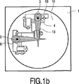
図1aは、光学式入力デバイスの概略横断面である。このデバイスは、その下側にベースプレート1を有する。ベースプレート1は、ダイオード・レーザ(本実施形態においてはVCSELタイプのレーザ)用及び検出器(例えば光ダイオード)用のキャリアである。図1aにおいて、ダイオード・レーザ3が1つだけとそれに関連した光ダイオード4が見えるが、通常、少なくとも第二のダイオード・レーザ5と関連した検出器6が本装置の上面図である図1bに示すようにベースプレート上に設けられる。ダイオード・レーザ3及び5は、レーザ・ビーム又は測定ビーム13及び17をそれぞれ発する。このデバイスは、その上側に、例えば人の指である物体15を動かすための透明窓12が設けられる。例えば平凸レンズであるレンズ10が、ダイオード・レーザとこの窓との間に配置される。このレンズは、透明窓の上側又はその近くに測定ビーム13及び17の焦点を合わせる。物体15がこの位置に存在する場合、それはビーム13を散乱させる。ビーム13の放射線の一部は、測定ビーム13の方向へ散乱し、該一部はレンズ10によってダイオード・レーザ3の放射面上に収束させられ、このレーザの空洞に再突入する。後述するように、空洞に戻ってくる放射線は、この空洞に変化を引き起こし、それにより、特に、ダイオード・レーザによって発せられるレーザ放射線の強度が変化する。この変化は、ダイオード・レーザ3の後ろの側に配置することが可能で、放射線変動を電気信号へ変換する光ダイオード4と、この信号を処理する電子回路18とによって検出することができる。また、測定ビーム17は、物体上に焦点が合わせられ、よって散乱し、散乱した放射線の一部はダイオード・レーザ5の空洞に再突入する。図1a及び1bに示す光ダイオード6の信号のための回路18及び19は、例示であり、より従来通りであってもよく、或いは、より従来通りでなくてもよい。図1bに示すように、これら回路は相互接続される。
FIG. 1a is a schematic cross section of an optical input device. This device has a
図2は、セルフミキシング効果を用いた移動測定の原理を示す。この図には、例えばダイオード・レーザ3であるダイオード・レーザがその空洞20によって概略的に表されている。ここで、ダイオード・レーザの前面及び後面は、レーザ・ミラー21及び22によってそれぞれ表されている。空洞は、長さLを有する。移動が測定される物体は、符号15で示される。この物体と前面21の間のスペースは、外部空洞を形成し、その長さはL0である。前面を通って発せられたレーザ光線は符号25で示され、前面の方向に物体により反射された放射線は符号26で示される。レーザ空洞において生成された放射線の一部は、後面を通過して、光ダイオード4によって捕らえられる。
FIG. 2 shows the principle of movement measurement using the self-mixing effect. In this figure, a diode laser, for example a
物体15が測定ビーム25の方向に移動する場合、反射された放射線26はドップラー・シフトを受ける。これは、この放射線の周波数が変化すること、又は、周波数シフトが発生すること、を意味する。この周波数シフトは、物体の移動速度に依存し、数kHz〜MHzのオーダーである。レーザ空洞に再突入した周波数シフトした放射線は、この空洞で生成された光波又は放射線と干渉する。すなわち、空洞においてセルフミキシング効果が発生する。光波と空洞に再突入した放射線との間の位相シフト量に応じて、この干渉は建設的か又は消極的である。すなわち、レーザ放射線の強度は、周期的に増加又は減少する。このように生成されたレーザ放射線変調の周波数は、空洞における光波の周波数と空洞に再突入したドップラー・シフトされた放射線の周波数との差にちょうど等しい。周波数の差は、数kHz〜MHzのオーダーであるため、容易に検出できる。セルフミキシング効果とドップラー・シフトの組み合わせは、レーザ空洞の挙動を変動させる。特に、そのゲイン又は光振幅が変化する。
When the
これを図3に示す。この図において、曲線31及び32は、物体15とフロント・ミラー21との間の距離L0に対する発せられたレーザ放射線の周波数νの変動及びダイオード・レーザのゲインgの変動をそれぞれ表す。ν、g、及びL0は、いずれも任意の単位である。距離L0の変動は物体移動の結果であるため、時間に対するゲインをプロットするために図3の横座標を時間軸でリスケールすることができる。物体の速度vに対するゲイン変動Δgは、以下の数式によって与えられる。
This is shown in FIG. In this figure, curves 31 and 32 represent the variation in the frequency ν of the emitted laser radiation and the variation in the gain g of the diode laser with respect to the distance L 0 between the

− Kは、外部空洞への結合係数であり、レーザ空洞外で結合された放射線量を表している。
− νは、レーザ放射線の周波数である。
− vは、測定ビーム方向における物体の速さである。
− tは、時間モーメントである。
− cは、光速である。
-K is the coupling coefficient to the external cavity and represents the radiation dose coupled outside the laser cavity.
Ν is the frequency of the laser radiation.
V is the speed of the object in the direction of the measurement beam.
T is the time moment.
C is the speed of light.
この数式は、上述の2つの「Appiled Optics」の文献に開示されたセルフミキシング効果に関する理論から導くことができる。物体表面は、図2の矢印16によって示されるように、それ自体の面において移動させられる。ドップラー・シフトはビーム方向における物体移動に対してのみ発生するため、この移動16はこの方向の成分16’を有するべきである。したがって、XZ面(すなわち、図2の図面平面)における移動(X移動と呼ぶ)を測定することができるようになる。図2は、物体表面がシステムの他の部分に対して斜めの位置をとっていることを示している。実際には、測定ビームは斜めのビームであり、物体表面の移動はXY面で発生するのが通常であろう。Y方向は、図2の図面平面に垂直である。この方向の移動は、第二の測定ビームによって測定することができる。第二の測定ビームは、第二のダイオード・レーザによって発せられ、その散乱光は、第二のダイオード・レーザに関連付けられた第二の光ダイオードによって捕らえられる。斜め照射ビームは、図1に示すように、ダイオード・レーザをレンズ10に対して偏心して配置することによって得られる。
This equation can be derived from the theory regarding the self-mixing effect disclosed in the above two "Applied Optics" documents. The object surface is moved in its own plane, as indicated by
監視ダイオードによってレーザ後面における放射線強度を測定することによって物体移動によって引き起こされたレーザ空洞ゲインの変動を測定することが、最もシンプルで、よって最も魅力的な方法である。従来、このダイオードは、レーザ放射線の強度を一定に保つために使われていたが、ここでは物体の移動を測定するのにも用いられる。 Measuring the laser cavity gain variation caused by object movement by measuring the radiation intensity at the back of the laser with a monitoring diode is the simplest and therefore the most attractive method. Traditionally, this diode has been used to keep the intensity of the laser radiation constant, but here it is also used to measure the movement of the object.
ゲイン変動を測定し、よって物体の移動を測定する別の方法は、レーザ放射線の強度がレーザの接点の伝導バンドにおける電子数に比例するという事実を利用する。次に、この数は、接点の抵抗に反比例する。この抵抗を測定することによって、物体の移動を割り出すことができる。この測定方法の一実施形態を図4に示す。この図において、ダイオード・レーザのアクティブ層は符号35で示され、このレーザを供給する電流源は符号36で示される。ダイオード・レーザに掛かる電圧は、コンデンサ38を経由して電子回路40へ供給される。レーザを通る電流によって正規化されるこの電圧は、レーザ空洞の抵抗又はインピーダンスに比例する。ダイオード・レーザと直列に配置されたインダクタンス37は、ダイオード・レーザを通る信号に対する高インピーダンスを構成する。
Another method of measuring gain variation and thus measuring object movement takes advantage of the fact that the intensity of laser radiation is proportional to the number of electrons in the conduction band of the laser contact. This number is then inversely proportional to the contact resistance. By measuring this resistance, the movement of the object can be determined. One embodiment of this measurement method is shown in FIG. In this figure, the active layer of the diode laser is indicated at 35 and the current source supplying this laser is indicated at 36. The voltage applied to the diode laser is supplied to the
移動量(すなわち、物体が移動した距離であって、測定された速度を時間積分することによって測定することができる)以外に、移動方向も検出されなければならない。これは、物体が移動軸に沿って前進したか又は後退したかを判断しなければならないことを意味する。移動方向を割り出す第一の方法は、セルフミキシング効果により生じた信号の形状を用いる。図3のグラフ32に示すように、この信号は非対称信号である。グラフ32は、物体15がレーザに向かって移動している状況を表している。上り勾配32’は、下り勾配32’’より急勾配である。上述の文献「Applied Optics、Vol.31、No.8、1992年6月20日、3,401〜3,408頁」に記載されているように、この非対称性は、レーザから離れていく物体の移動に対しては逆になる。すなわち、下り勾配が上り勾配よりも急勾配となる。セルフミキシングした信号の非対称性の種類を判断することによって、物体の移動方向を確認することができる。
In addition to the amount of movement (ie, the distance that the object has moved and can be measured by time integrating the measured velocity), the direction of movement must also be detected. This means that it must be determined whether the object has advanced or retracted along the movement axis. The first method for determining the direction of movement uses the shape of the signal produced by the self-mixing effect. As shown in
例えば物体の反射係数が比較的小さい場合又は物体とダイオード・レーザとの間の距離が比較的大きい場合などの特定の状況下では、セルフミキシングした信号の形状又は非対称性を判断することが困難となる場合もある。したがって、第二の移動方向を判断する方法が好ましいかもしれない。この第二の方法は、レーザ放射線の波長λはダイオード・レーザの温度、引いてはそれを通る電流、に依存するという事実を利用する。例えば、ダイオード・レーザの温度が上昇した場合、レーザ空洞の長さは長くなり、増幅される放射線の波長は大きくなる。図5の曲線45は、発せられた放射線の波長λの温度(Td)依存性を示す。この図において、水平軸Tdと縦軸λはいずれも任意の単位である。
Under certain circumstances, such as when the reflection coefficient of the object is relatively small or when the distance between the object and the diode laser is relatively large, it may be difficult to determine the shape or asymmetry of the self-mixed signal. Sometimes it becomes. Therefore, a method of determining the second moving direction may be preferable. This second method takes advantage of the fact that the wavelength λ of the laser radiation depends on the temperature of the diode laser and hence the current through it. For example, when the temperature of a diode laser increases, the length of the laser cavity increases and the wavelength of the amplified radiation increases.
図6に示すようにグラフ50で表された周期的な駆動電流Idがダイオード・レーザに供給される場合、ダイオード・レーザの温度Tdは、グラフ52に示すように、周期的に上昇及び下降する。これにより、定常光波がレーザ空洞に生じる。この定常光波は、周期的に変化する周波数を持ち、よって、物体によって反射されて、ある程度の時間遅延を伴って空洞に再突入する放射線に対して連続的な変化する位相シフトを持つ。ここでは、駆動電流の半周期ごとに、ダイオード・レーザ利得が空洞における波と空洞に再突入する反射された放射線との位相相関に応じて高い/低いを交互に繰り返す連続した時間セグメントが存在する。これは図6のグラフ54に示すように、発せられた放射線の時間依存強度変動(I)をもたらす。このグラフは、静止して、移動していない物体についての状況を表している。前半期間1/2p(a)におけるパルス数は、後半期間1/2p(b)におけるパルス数と等しい。
As shown in FIG. 6, when the periodic drive current I d represented by the
物体の移動により、レーザ空洞に再突入する放射線にドップラー・シフトが生じる。すなわち、この周波数は、移動方向に応じて増加又は減少する。一方向(前進方向)への物体の移動により再突入する放射線の波長は小さくなり、反対方向への移動によりこの放射線の波長は大きくなる。レーザ空洞における光波の周期的な周波数変調の効果は以下の通りである。ドップラー・シフトがレーザ空洞における周波数変調と同じ符号を有する場合、空洞に再突入するドップラー・シフトした放射線の効果は、上記周波数変調とドップラー・シフトとが反対の符号を有する場合にこの放射線が有する効果と異なる。これら2つの周波数シフトが同じ符号を持つ場合、波と再突入放射線との間の位相差はゆっくりと変化し、得られるレーザ放射線の変調の周波数が低くなる。これら2つの周波数シフトが反対の符号を持つ場合、波と放射線との間の位相差はより速く変化し、得られるレーザ放射線の変調の周波数が高くなる。駆動レーザ電流の前半期間1/2p(a)の間に、生成されたレーザ放射線の波長は大きくなる。物体が後退する場合、再突入する放射線の波長も大きくなるため、空洞における波の周波数とこの空洞に再突入する放射線の周波数との差が小さくなる。このように、再突入する放射線の波長が生成された放射線の波長に合っている時間セグメントの数は、発せられたレーザ放射線の電気変調がない場合よりも小さい。これは、物体が後退する場合、前半期間におけるパルス数が何らの変調も適用されない場合より小さいことを意味している。レーザ温度及び生成された放射線の波長が低下する後半期間1/2p(b)において、再突入する放射線の波長が生成された放射線の波長に合っている時間セグメントの数は増える。このように、後退する物体については、前半期間におけるパルス数が後半期間におけるパルス数より小さい。これを図7のグラフ58に示す。このグラフは、物体が後方へ移動する場合に発せられたレーザ放射線の強度Ibを示す。このグラフを図6のグラフ54と比較すると、前半期間におけるパルス数が減少し、後半期間におけるパルス数が増加していることがわかる。
The movement of the object causes a Doppler shift in the radiation that re-enters the laser cavity. That is, this frequency increases or decreases depending on the moving direction. The wavelength of the re-entry radiation is reduced by moving the object in one direction (forward direction), and the wavelength of the radiation is increased by moving in the opposite direction. The effect of periodic frequency modulation of light waves in the laser cavity is as follows. If the Doppler shift has the same sign as the frequency modulation in the laser cavity, the effect of the Doppler shifted radiation re-entering the cavity has this radiation if the frequency modulation and the Doppler shift have opposite signs Different from effect. If these two frequency shifts have the same sign, the phase difference between the wave and the re-entry radiation will change slowly, resulting in a lower modulation frequency of the laser radiation. If these two frequency shifts have opposite signs, the phase difference between the wave and the radiation will change faster and the resulting frequency of modulation of the laser radiation will be higher. During the
上記説明から明らかなように、物体が前方へ移動する場合、すなわち、物体によって散乱されてレーザ空洞に再突入する放射線の波長がドップラー効果により減少する場合、前半期間1/2p(a)におけるパルス数が後半期間1/2p(b)におけるパルス数より大きくなる。これは、物体が前進している場合に発せられた放射線の強度Ifを表す図7のグラフ56と比較することによって確認することができる。電子処理回路において、後半期間1/2p(b)中に計数された光ダイオード信号パルス数が、前半期間1/2p(a)中に計数されたパルス数から減算される。得られた信号が0である場合、物体は静止している。得られた信号が正の場合、物体は前進しており、この信号が負の場合、物体は後退している。これら得られたパルス数は、前進速度及び後退速度にそれぞれ比例している。
As is clear from the above description, when the object moves forward, that is, when the wavelength of the radiation scattered by the object and re-entering the laser cavity is reduced by the Doppler effect, the pulse in the
特定の状況下では、ドップラー効果によって生成されたパルス数が電気変調によって生成されたパルス数より多いこともあり得る。これは、例えば、レーザと物体の間の光路長が比較的小さく、電気変調の周波数及び振幅が比較的小さいにもかかわらず、検出する移動が比較的速い場合など、に起こり得る。このような状況において、移動方向は、依然として、前半期間におけるパルス数を後半期間におけるパルス数と比較することによって検出することができる。しかし、その際、速度はこれらの2つの数の差に比例しない。このような状況において速度を求めるには、上述の2つの数を平均して、そこから定数を減算するべきである。このようにして得られた数は、速度の指標である。当業者は、この計算を実行する電子回路を容易に設計することができる。 Under certain circumstances, the number of pulses generated by the Doppler effect may be greater than the number of pulses generated by electrical modulation. This can occur, for example, when the optical path length between the laser and the object is relatively small and the frequency of electrical modulation is relatively small, but the detected movement is relatively fast. In such a situation, the direction of travel can still be detected by comparing the number of pulses in the first half period with the number of pulses in the second half period. However, the speed is not proportional to the difference between these two numbers. To determine the speed in such a situation, the above two numbers should be averaged and a constant subtracted from there. The number thus obtained is an indicator of speed. One skilled in the art can easily design an electronic circuit that performs this calculation.
図5及び6を参照して説明した実施形態において用いられる三角波の駆動電流Idの代わりに、正弦波や矩形波などの別の形の駆動電流を用いることもできる。 Instead of the drive current I d of the triangular wave used in the embodiment described with reference to FIGS. 5 and 6, it is also possible to use another form of drive current such as a sine wave or a rectangular wave.
上述の物体移動の速度及び方向を測定する方法は、ゲイン変動がダイオード・レーザ空洞の抵抗の変動を測定することによって求められる場合においても用いることができる。 The method of measuring the speed and direction of object movement described above can also be used when gain variation is determined by measuring the variation in resistance of the diode laser cavity.
この測定方法は、小さいドップラー・シフト、波長で言えば例えば1.5×10⁻¹⁶mオーダーのシフト、しか必要としない。このシフトは、680nmのレーザ波長に対して100kHzオーダーのドップラー周波数シフトに相当する。 This measuring method only requires a small Doppler shift, for example a shift of the order of 1.5 × 10 −16 m in terms of wavelength. This shift corresponds to a Doppler frequency shift on the order of 100 kHz for a laser wavelength of 680 nm.
垂直方向に2つのダイオード・レーザと2つの関連した光ダイオードとを有する図1の入力デバイスは、1つの平面において、2つの直交する(X及びY)方向又は測定軸に沿って物体の移動を測定することを可能にする。このようなデバイスは、ディスプレイ上において2方向へのカーソルの移動が制御されなければならない装置に適切である。このような装置において、クリック・アクションも測定されなければならない場合、第三のダイオード・レーザ及び関連した光ダイオードが該デバイスに追加されなければならない。これら第三のダイオード・レーザ及び光ダイオードにより、該デバイスは、第三のZ方向又は測定軸に沿った移動も測定できるようになる。この第三のダイオード・レーザは、第三の測定ビームが窓12及び物体に垂直に入射し、他方向成分を一切持たないように、レンズ10の光軸上に配置することが可能である。その際、Z方向について最適な測定信号を得ることができる。X及びY測定信号の信頼性及び精度を向上させるためには、3つのダイオード・レーザは1つの円上に120°の角度間隔で配置されることが好ましい。この構成を図8に示す。図8では、第三のダイオード・レーザ及び第三の光ダイオードがそれぞれ符号7及び8で示されている。光ダイオード4、6、及び8の出力信号又は抵抗測定信号はS4、S6、及びS8でそれぞれ表され、X、Y、及びZ測定軸にそれぞれ沿った物体速度Vx、Vy、及びVzは、例えば以下のように計算することができる。
Vx=2S4−S6−S8
Vy=√3・(S8−S6)
Vz=1/√2・(S4+S6+S8)
この計算を実行する電子回路は、加算要素及び減算要素を有し、実施が比較的容易である。
The input device of FIG. 1, which has two diode lasers and two associated photodiodes in the vertical direction, can move the object along two orthogonal (X and Y) directions or measurement axes in one plane. Makes it possible to measure. Such a device is suitable for an apparatus in which the movement of the cursor in two directions on the display must be controlled. In such an apparatus, if a click action must also be measured, a third diode laser and associated photodiode must be added to the device. These third diode lasers and photodiodes also allow the device to measure movement along the third Z direction or measurement axis. This third diode laser can be placed on the optical axis of the
V x = 2S 4 -S 6 -S 8
V y = √3 · (S 8 −S 6 )
V z = 1 / √2 · (S 4 + S 6 + S 8 )
The electronic circuit that performs this calculation has an addition element and a subtraction element and is relatively easy to implement.
このようにして得られたX及びY方向における移動の速度値及び時間積分による移動距離は、それらが、少なくとも2つの光ダイオードの出力信号を平均して得られた結果であるため、より信頼性が高く、正確である。わずかに指を持ち上げるなどの移動エラー又は望まれない移動は、光ダイオードの出力信号に類似の影響を及ぼす。X及びY測定軸に沿った移動は互いからの出力信号を引くことによって求められるため、X及びY測定信号上での望まれない移動の影響は除去される。3つの光ダイオードの出力信号を加算することによって得られたZ測定信号Vzだけが指又は別の物体の上下移動を表す。 The speed values of movement in the X and Y directions and the movement distance by time integration obtained in this way are the results obtained by averaging the output signals of at least two photodiodes, so that they are more reliable. Is high and accurate. Movement errors or unwanted movements, such as lifting a finger slightly, have a similar effect on the output signal of the photodiode. Since movement along the X and Y measurement axes is determined by subtracting output signals from each other, the effects of unwanted movement on the X and Y measurement signals are eliminated. Only the Z measurement signal V z obtained by adding the output signals of the three photodiodes represents the vertical movement of the finger or another object.
クリック・アクションを判断するためには、このような移動が発生したことを検出すれば十分であり、物体の変位の正確な測定は必要ではないため、Z測定値は幾分粗くなり得る。 To determine the click action, it is sufficient to detect that such movement has occurred, and an accurate measurement of the displacement of the object is not necessary, so the Z measurement can be somewhat coarse.
ダイオード・レーザ、引いては測定ビームのデバイス窓に対する適正な配置及び光ダイオードの信号の適正な処理により、ダイオード・レーザを2つしか備えていない入力デバイスを用いてもX、Y、及びZ方向における測定が可能となる。この入力デバイスは、メニュ・チャートをスクロール及びクリックする機能を備えた装置において用いることができる。光学式スクロール・アンド・クリック・デバイスとも言えるこのような入力デバイスは、離散的な構成要素から容易に組み立てることができ、新しい開発を速く行うことが可能となる。 The diode laser, and hence the proper placement of the measurement beam with respect to the device window and the proper processing of the photodiode signal, makes it possible to use X, Y, and Z directions even with input devices with only two diode lasers. Measurement at is possible. This input device can be used in an apparatus having a function of scrolling and clicking a menu chart. Such an input device, which can be referred to as an optical scroll-and-click device, can be easily assembled from discrete components, enabling rapid new development.
図9は、光学式スクロール・アンド・クリック入力デバイス60の第一の実施形態を示す。これは、各々がダイオード・レーザ及び光ダイオードのアセンブリ66、68を有し得る2つの光学式センサ・ユニット62、64を有する。このようなアセンブリの代わりに、別体のダイオード・レーザ及び光ダイオードを用いることもできる。ユニット62、64によって発せられた放射線路中に、レンズ70、72がそれぞれ配置される。これらレンズは、例えば窓と同じ平面の作用面88に関連したユニット62、64の放射線ビーム74、76)の焦点を合わせる。この窓78は、本デバイスが用いられている装置(例えば、図10に側面図で示したような携帯電話など)のハウジング82の一部を構成する。これらセンサ・ユニットは、測定ビーム74、76の主光線が窓78の法線に対して反対の角度(例えば、+45°及び−45°)となるように配置される。
FIG. 9 shows a first embodiment of an optical scroll and click
物体(例えば人の指)80は、スクロール・アクション及び/又はクリック・アクションのために作用面上を移動する。上述のように、両アクションとも指によってレーザ/ダイオード・アセンブリ・ユニット66、68へ向けて反射された放射線にドップラー・シフトを生じさせる。これらのユニットの検出器の出力信号は、信号処理/レーザ駆動電子回路84へ供給される。この回路は、例えば制御指80の移動を評価し、これら移動に関する情報をその出力86において供給する。センサ・ユニット62、64、窓88、並びに、電子回路84及びソフトウェアは、1つのモジュールに統合することも可能である。このモジュールは、それ自体、携帯電話内に置かれてもよく、或いは、スクロール・アンド・クリック機能を備えた別の装置内に置かれてもよい。離散した要素を用いてこの入力デバイスを実施することも可能である。特に、信号処理の一部は、携帯電話又は他の装置(例えば、リモコン、コードレス電話、ポータブル・コンピュータなど)の一部を構成するマイクロコントローラ又は他の制御手段によって実行することができる。
An object (eg, a human finger) 80 moves on the working surface for scroll and / or click actions. As described above, both actions cause a Doppler shift in the radiation reflected by the finger toward the laser /
上述のように、センサ・ユニットに対する指などの移動は、レーザ電流を調節し、検出器によって受信されたパルスを計数することによって検出することができる。測定ビーム74、76の主光線に沿った物体の速度を表すこれらの検出器の出力信号Sign1及びSign2から、窓に平行な速度Vscroll及び窓に垂直な速度Vclickを以下のように計算することができる。
Vscroll=1/2√2(Sign1−Sign2)
Vclick=1/2√2(Sign1+Sign2)
図11は、スクロール・アンド・クリック入力デバイス90の第二の実施形態を示す。この実施形態は、2つのレンズ70、72及び窓88が1つの構成要素92によって置き換えられている点で、図9及び10のものと異なる。この要素は、両方のビーム74、76の焦点を窓を構成するその上面94に合わせる。
As described above, movement of a finger or the like relative to the sensor unit can be detected by adjusting the laser current and counting the pulses received by the detector. From these detector output signals Sign 1 and Sign 2 representing the velocity of the object along the chief ray of the measurement beams 74, 76, the velocity V scroll parallel to the window and the velocity V click perpendicular to the window are as follows: Can be calculated.
V scroll = 1 / 2√2 (Sign 1 -Sign 2 )
V click = 1 / 2√2 (Sign 1 + Sign 2 )
FIG. 11 shows a second embodiment of the scroll and click input device 90. This embodiment differs from that of FIGS. 9 and 10 in that the two
ここまで記載してきたように、スクロール・アクション及びクリック・アクションは、すべての入手可能な方向に関する情報(すなわち、入力デバイスに存在するすべての検出器の信号)をベクトル変換することによって求められる。状況によっては、スクロール・アクションとクリック・アクションの区別、及び、スクロール・アクション及びクリック・アクションにおける前進と後退の区別、が難しい場合もある。特に、デバイスが更に小型化されて、センサ信号の信号対雑音比が低下したときに、後者のケースとなり得る。本発明は、これらの問題を解決する方法を提供し、さらに、デバイス内のダイオード・レーザの数を減らすことを可能にする。後者は、大幅なコスト及びスペースの低減を実現することができることを意味している。この新しい方法は、スクロール・アクション及びクリック・アクションの間に生成された信号の時間依存特性と、より信頼性の高い信号解釈を得るための先行アクションの履歴データとを用いる。履歴データを用いることによって、漠然とした信号を今のところ良好に解釈することができるように、確率チェックを実行することができる。 As described so far, scroll and click actions are determined by vectorizing all available direction information (ie, all detector signals present in the input device). In some situations, it may be difficult to distinguish between a scroll action and a click action, and to distinguish between forward and backward in a scroll action and a click action. In particular, the latter case can occur when the device is further miniaturized and the signal-to-noise ratio of the sensor signal is reduced. The present invention provides a method to solve these problems, and further allows the number of diode lasers in the device to be reduced. The latter means that significant cost and space savings can be realized. This new method uses the time-dependent properties of the signal generated during scroll and click actions and historical data of previous actions to obtain a more reliable signal interpretation. By using historical data, a probability check can be performed so that a vague signal can now be interpreted well.
この新しい方法の出発点は以下の事実である。
− ユーザは、決してスクロールとクリックを同時には行わない。
− スクロール・アクションの時間依存特性は、クリック・アクションの特性と大きく異なる。
これらの事実は、センサ信号を解釈するソフトウェアに組み込むことができる。このソフトウェアは、入力デバイス及び/又は入力デバイスが埋め込まれた装置の一部を構成する。第一の事実は、故意のスクロール・アクションと故意のクリック・アクションの間のクロストークは不可能であることを意味する。第二の事実を図12及び13に示す。
The starting point of this new method is the following facts.
-The user never scrolls and clicks at the same time.
-The time-dependent characteristics of scroll actions are very different from those of click actions.
These facts can be incorporated into software that interprets sensor signals. This software forms part of the input device and / or the device in which the input device is embedded. The first fact means that crosstalk between a deliberate scroll action and a deliberate click action is not possible. The second fact is shown in FIGS.
図12は、セルフミキシング効果を用いるスクロール・アンド・クリック・デバイスによって供給されたクリック信号Sclick示す。水平軸は時間(t)軸であり、縦軸に沿って、クリック・アクション中のレーザパルス総数Npがプロットされている。通常、クリック・アクションの際に、ユーザは、クリックする前に、スクロール速さを低減し、最終的には所望の位置に到着した時にスクロールを停止する。そして、素早いクリック・アクションが実行され、その後には移動のない期間が続く。素早いクリック・アクションの各々は、多数のダイオード・レーザ・パルスを生じさせ、図12から分かるように信号SclickにピークCpを生じさせる。図12は、このようなピークを複数個示している。これは、交互に実行された対応した数のクリック・アクションにより生じたものである。図12に示した信号パターンは、常に起こるであろう一般的なクリック・パターンであり、ユーザによって異ならず、ユーザによって為されたアップ・クリック又はダウン・クリックによって異ならない。 FIG. 12 shows the click signal S click supplied by the scroll and click device using the self-mixing effect. The horizontal axis is the time (t) axis, along a longitudinal axis, the laser pulse total number N p in click action is plotted. Typically, during a click action, the user reduces the scrolling speed before clicking and eventually stops scrolling when it reaches the desired position. A quick click action is then performed, followed by a period of no movement. Each of the quick click actions produces a number of diode laser pulses, causing a peak C p in the signal S click as can be seen in FIG. FIG. 12 shows a plurality of such peaks. This is caused by a corresponding number of click actions performed alternately. The signal pattern shown in FIG. 12 is a general click pattern that will always occur, does not vary from user to user, and does not depend on the up or down click made by the user.
図13は、複数のスクロール・アクションが次々に実行されたときに同じ入力デバイスによって供給されるスクロール信号Sscrollを示す。1回のスクロール・アクションの間、指はずっと移動する。速度は通常一定でないため、スクロール・アクション期間中の時間間隔ごとに、ダイオード・レーザ・パルスの数は異なる。これにより、各スクロール・アクションについて波状(Su)スクロール信号が生じる。また、この信号は、複数のピークSpを有するが、ここで、スクロール・アクションの始まり及び終わり並びにこれらピークは、通常、図12のクリック信号のピークより低い。 FIG. 13 shows the scroll signal S scroll supplied by the same input device when a plurality of scroll actions are executed one after the other. During a single scrolling action, the finger moves all the way. Since the speed is usually not constant, the number of diode laser pulses is different for each time interval during the scroll action. This produces a wavy (Su) scroll signal for each scroll action. This signal also has a plurality of peaks Sp, where the beginning and end of the scroll action and these peaks are usually lower than the click signal peak of FIG.
図12のグラフSclickと図13のSscrollとの比較から、クリック・アクションがクリック・アクションによって生成されたセンサ信号とは大幅に異なるセンサ信号を生成することが分かる。これらの信号の異なる時間特性を検出することができるため、追加的アルゴリズムを用いてクリック・アクションとスクロール・アクションを区別することができる。このアルゴリズムは、入力デバイスのソフトウェアに埋め込まれる。このソフトウェアは、デバイスの信号プロセッサ内に記憶されるか、或いは、装置のマイクロプロセッサ内に記憶される。 Comparison with S scroll graph S the click and Figure 1 3 in FIG. 12, it can be seen that generate different sensor signals significantly from sensor signals generated click action by a click action. Because different time characteristics of these signals can be detected, additional algorithms can be used to distinguish between click and scroll actions. This algorithm is embedded in the input device software. This software can be stored in the signal processor of the device or stored in the microprocessor of the apparatus.
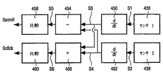
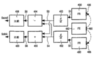
スクロール・アクションについては、2つのパラメータが興味深い。1つは、正の値しか採らない速さであり、1つは正の値(アップ・スクロール)も負の値(ダウン・スクロール)も採り得るスクロール方向である。例えば10ミリ秒ごとなどの規則的な時間間隔で、スクロール・アクション又はクリック・アクション中に、信号プロセッサは、検出器信号を取り込み、これら信号を適正に合成することによって、速さ及び方向についての数値を計算する。信号プロセッサは、関連したダイオード・レーザのウォームアップ運転段階中に検出器によって生成された信号とダイオード・レーザのクールダウン段階中に生成された信号の双方を取り込む。これらの段階を図6に示す(グラフ52)。図6及び7の手において記載したように、そこでは半周期と呼ばれるこれらの段階中のレーザパルスの数は、物体(指)の速さと物体移動の方向とに依存する。また、これは、これら段階の間、出力パルスについて検出器サプライも保持する。この出力パルスは、検出器ごとに別個のカウンタによって計数される。したがって、このようなカウンタは、スクロール・アクションが発生したときに上記複数の段階の間に様々な値を供給し、よってこれら値の差はスクロール方向を表している。 Two parameters are interesting for the scroll action. One is a speed that takes only a positive value, and one is a scrolling direction that can take a positive value (up scroll) or a negative value (down scroll ). At regular time intervals, such as every 10 milliseconds, during a scroll or click action, the signal processor captures the detector signals and synthesizes them appropriately to ensure speed and direction. Calculate numerical values. The signal processor captures both the signal generated by the detector during the associated diode laser warm-up phase and the signal generated during the diode laser cool-down phase. These stages are shown in FIG. 6 (graph 52). As described in the hands of FIGS. 6 and 7, the number of laser pulses during these stages, called half-cycles there, depends on the speed of the object (finger) and the direction of object movement. It also holds the detector supply for output pulses during these phases. This output pulse is counted by a separate counter for each detector. Thus, such a counter provides various values during the plurality of stages when a scroll action occurs, and thus the difference between these values represents the scroll direction.
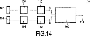
図14は、2つの検出器102、104と信号プロセッサ84の一部の構成要素との詳細を概略的に示す。符号110及び112は、検出器110及び112からのパルスを計数するカウンタをそれぞれ示す。数値であるカウンタ出力値A、Bは、計算機100に供給される。検出器とカウンタの間に検出器信号を増幅する増幅器106、108を配置することもできる。例えば10ミリ秒ごとなどのサンプリング瞬間の各々において、上記2つの半周期中に得られた値A及びBを加算すると物体移動の瞬間的な速度が得られ、互いに引き算すると物体移動の方向が得られる。
FIG. 14 schematically shows details of the two
一般的に、満足のいく結果はこのようにして得られる。しかし、入力デバイスを更に小型化したい場合、検出器信号へのノイズの影響が増加し、2つの半周期中の信号間の差を検出するのがより難しくなる。これは、計算機の出力114の信頼性が減少することを意味する。しかし、スクロール・アクションの速度及び方向に関する信頼性の高い情報及びクリック・アクションに関する信頼性の高い情報は、以下の事実を利用するとき、比較的信頼性の低い測定信号からであっても得ることができる。
− ユーザは特定の時間期間中に複数回スクロール方向を変更しない。
− スクロール方向が変更されるとき、速さは低い。数学的に言えば、無限短時間間隔について速さは0である。実際に分析される時間間隔前後の他の時間間隔におけるユーザ入力に関する情報を用いて、上記実際の時間間隔中に得られたセンサ信号を解釈して該実際の時間間隔におけるスクロール移動方向に関する信頼性の高い情報を得ることができる。
In general, satisfactory results are obtained in this way. However, if the input device is desired to be further miniaturized, the effect of noise on the detector signal increases and it becomes more difficult to detect the difference between the signals in the two half-cycles. This means that the reliability of the computer output 114 is reduced. However, reliable information about the speed and direction of the scroll action and reliable information about the click action can be obtained even from a relatively unreliable measurement signal when using the following facts: Can do.
-The user does not change the scroll direction more than once during a specific time period.
-The speed is low when the scroll direction is changed. Mathematically speaking, the speed is zero for an infinite short time interval. Using information about user input in other time intervals before and after the actual time interval to be analyzed, the sensor signal obtained during the actual time interval is interpreted to determine the reliability of the scrolling direction in the actual time interval. High information can be obtained.
この新しい方法は、スクロール・アクションとクリック・アクションを区別するのにベクトル分解法を用いないため、この方法により光学式センサ・ユニットを1つしか用いなくてもこれらアクションの測定ができるようになる。 This new method does not use a vector decomposition method to distinguish between scroll and click actions, so this method allows these actions to be measured using only one optical sensor unit. .
図15は、光学式センサ・ユニット122を1つだけ有する光学式スクロール・アンド・クリック・デバイス120の一実施形態を概略的に示し、図16はこのようなデバイスが実施され得る携帯電話の側面図を示す。センサ・ユニットは、ダイオード・レーザ・光ダイオード・アセンブリ124と、指132を載せて動かすデバイス窓130の面又はこの窓の周囲の面に測定ビーム128の焦点を合わせるためのレンズ126と、を有する。このデバイスは、更に、レーザ駆動/信号検出回路136を有する。この回路136は、ここで説明したアルゴリズムを埋め込み得るソフトウェアを有し得る。また、このソフトウェアは、入力デバイスがその一部を構成する装置のマイクロプロセッサ内に配置することもできる。符号138は、例えば携帯電話メニュと関連する外部機能を制御するためのデバイス出力及び/又はインタフェースを示す。
FIG. 15 schematically illustrates one embodiment of an optical scroll and click
測定ビームの主光線は窓130及び指表面に鋭角に入射するため、単一のセンサ・ユニット122で、窓に垂直な移動(クリック・アクション)だけでなく、窓に平行な移動(スクロール・アクション)も測定することができる。このデバイスにおいて、クリック・アクションは、指の移動の窓に垂直な方向の成分を求めることによってではなく、検出器信号の時間特性を分析することによって、検出される。
Since the chief ray of the measurement beam is incident on the
また、原理として3つのセンサ・ユニット(1方向について1つ)が用いられ、3つの方向(Xスクロール、Yスクロール、及びクリック)において物体の移動を測定する入力デバイスにおいて、この方法を用いるとき、センサ・ユニットを1つ省くことができる。センサ・ユニットの節約では、特に、ダイオード・レーザが現実的には非常に重要となり得る。なぜなら、ダイオード・レーザは入力デバイスの中で最も高価な部品であるからである。さらに、センサ・ユニットを節約することは、このデバイスをよりコンパクトにできること、及び、心に描かれた装置により容易に組み込むことができること、を意味する。この新しい方法は、センサ・ユニットを元々の数備えた入力デバイスを用いても使用することができる。センサ・ユニットの1つは、2つの方向に沿った移動を測定するのに用いることができ、元々はこれら方向の一方に沿って測定していた残りのセンサ・ユニットは、今回、追加的情報を生成するのに利用可能である。 Also, when using this method in an input device that measures the movement of an object in three directions (X scroll, Y scroll, and click) using three sensor units (one per direction) in principle, One sensor unit can be omitted. In terms of sensor unit savings, in particular, diode lasers can be very important in practice. This is because the diode laser is the most expensive part of the input device. Furthermore, saving the sensor unit means that the device can be made more compact and can be easily integrated with the device depicted in the mind. This new method can also be used with input devices with the original number of sensor units. One of the sensor units can be used to measure movement along two directions, and the remaining sensor units that were originally measuring along one of these directions now have additional information. Can be used to generate
次に、本方法を実行するのに用いられるアルゴリズムのいくつかの実施形態を説明する。図17〜20は、1回のスクロール・アクション(X又はY)及びクリック・アクションを判断するのに用いることができるアルゴリズムのブロック図を示す。これらアルゴリズムの各々は、過去の、すなわち実際の測定・分析時間間隔の前の、ユーザ入力又はアクションに関するデータを記憶し、これらデータをこの間隔で用いる能力を有する。以下、ユーザ・アクションをイベントと呼ぶ。アルゴリズムは、実際のイベントに先行する最後のn回のイベントの間に入力デバイスの状態がチェックされたときに得られた完全なデータを記憶することができる。また、このアルゴリズムは、最後のイベント(クリック又はスクロール移動)が検出されてからの期限切れ時間などの処理された情報に関するデータのみを記憶してもよい。アルゴリズムは、それに加えて、瞬間的に分析された時間間隔に続くイベントに関するデータを用いてもよい。これは、幾分かの時間遅延後に入力信号を処理することによって実現することができる。 Next, some embodiments of the algorithm used to perform the method will be described. Figures 17-20 show block diagrams of algorithms that can be used to determine a single scroll action (X or Y) and click action. Each of these algorithms has the ability to store data relating to user input or actions in the past, ie prior to the actual measurement and analysis time interval, and to use these data in this interval. Hereinafter, the user action is referred to as an event. The algorithm can store the complete data obtained when the state of the input device was checked during the last n events preceding the actual event. The algorithm may also store only data relating to processed information such as the expiration time since the last event (click or scroll movement) was detected. In addition, the algorithm may use data regarding events that follow the time interval analyzed instantaneously. This can be achieved by processing the input signal after some time delay.
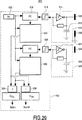
後者のアルゴリズムの一例のブロック図又はフローチャートを図17に示す。このアルゴリズムは、クリック・アクションの発生についてチェックされる時間間隔の前の10サイクルと後の10サイクルに関するデータを用いる。したがって、測定は、20の時間間隔から成るフィールドで行われる。図17においては、これらの時間間隔を「[I]」で示す。このアルゴリズムは、1つの光学式センサ・ユニットと1つのカウンタとを有し、カウンタ出力Aのみを供給する入力デバイスについて用いることができる。また、このアルゴリズムは、2つのセンサ・ユニットと2つのカウンタとを有し、2つのカウンタ出力A及びBを供給する入力デバイスに対しても用いることができる。これらの可能性について、図17の右上及び左上の部分にブロック210及び204としてそれぞれ示す。前半期間(ダイオード・レーザのウォーミングアップ)中のカウンタ値及び後半期間(ダイオード・レーザのクーリングダウン)中のカウンタ値の双方が用いられる。前半期間及び後半期間は、添字「up」及び「down」でそれぞれ示される。したがって、ブロック212及び206にそれぞれ示すように、センサが1つのデバイスに対してはカウンタ値Aup及びAdownが用いられ(ブロック212)、センサが2つのデバイスに対しては、カウンタ値Aup、Adown、Bup、及びBdownが用いられる。
A block diagram or flowchart of an example of the latter algorithm is shown in FIG. This algorithm uses data about the 10 cycles before and after the time interval checked for the occurrence of a click action. Therefore, the measurement is performed in a field consisting of 20 time intervals. In FIG. 17, these time intervals are indicated by “[I]”. This algorithm can be used for input devices that have one optical sensor unit and one counter and provide only counter output A. The algorithm can also be used for input devices that have two sensor units and two counters and provide two counter outputs A and B. These possibilities are shown as
ブロック208及び216において、移動速度及びスクロール移動方向が求められる。速度はすべてのカウンタ値の合計であるため、「sum」で示す。速度の方向は、同じカウンタの「up」値と「down」値の差である。センサが2つのデバイスでは、速度の方向は、2つのカウンタそれぞれにおける2つの差の間の差である。移動速度及び方向は、図17に示す瞬間的測定において考慮される最後の間隔であるI=20について計算される。 In blocks 208 and 216, the movement speed and scroll movement direction are determined. Since the speed is the sum of all counter values, it is indicated by “sum”. The direction of speed is the difference between the “up” value and the “down” value of the same counter. For devices with two sensors, the direction of velocity is the difference between the two differences in each of the two counters. The travel speed and direction are calculated for I = 20, the last interval considered in the instantaneous measurement shown in FIG.
ブロック218及びそれに続くブロックは、センサが1つのデバイスとセンサが2つのデバイスに共通である。この先行する時間間隔0〜19のブロック・データは、シフトレジスタを移動させることによって呼び起こされる。ブロック220において、パラメータclick_vについてi=10のときの値が計算される。このパラメータは、時間間隔10においてクリック・アクションが実行された確率を表す。この計算には、間隔10のデータだけでなく、間隔9及び11のデータも用いられる。計算されたclick_vの値は、ブロック222において、記憶されたクリック閾値と比較され、計算値が閾値より大きいとき、時間間隔10においてクリック・アクションが実行されたと判明する(ブロック224)。計算値が閾値より小さいとき(ブロック226)、図17のブロック226に示すように、別のアルゴリズムによって分析を続行し、スクロール方向を求めることができる。
後者のアルゴリズムを図18に示す。このアルゴリズムを用いると、スクロール方向検出の信頼性が大幅に増大する。これは、実際に速度が分析される時間間隔の前のいずれの時間間隔と後の時間間隔のいずれとのsum[i]が最小となるかを判断することによって実現される。これらの時間間隔の間の時間に移動方向は変化しないことを前提とする。なぜなら、理論上、速さで0でないと方向を変えることはできないからである。 The latter algorithm is shown in FIG. Use of this algorithm greatly increases the reliability of scroll direction detection. This is achieved by determining which time interval before and after the time interval where the velocity is actually analyzed has the smallest sum [i]. It is assumed that the direction of movement does not change during the time between these time intervals. This is because, in theory, the direction cannot be changed unless the speed is zero.
図18のステップ228において、時間間隔I=0〜I=9の中から最小のsum[i]が測定された時間間隔mが求められる。ステップ230において、同じ処理が時間間隔i=10〜I=20に対して行われる。求められた時間間隔はnである。次いで、パラメータav_dirの値が求められる(ステップ232)。このパラメータは、mとnの間のiについて測定された方向の値dir[i]の平均を表す。計算されたav_dirの値は、ステップ234において、記憶されたスクロール閾値と比較され、計算値が記憶された値より大きいとき、時間間隔i=10においてスクロール・アクションが実行されたが判明する(ステップ238)。スクロール移動方向は、ちょうど測定されたav_dirであり、スクロール移動速さはsum[10]である。av_dirの計算値がスクロール閾値より小さい場合、ステップ236において、スクロール・アクションは実行されなかったことが確認される。これを「方向=0」及び「速度=0」で示す。
In
図17及び18のアルゴリズムは、実際に分析される時間間隔ではない時間間隔において測定されたデータを記憶する。測定する時間間隔中に得られたデータの分析を遅延させることによって、この分析にこの測定する時間間隔前後の間隔からのデータを用いることができ、これにより入力デバイスの信頼性がより高い、これまで存在していないレベルに向上する。このアルゴリズムは情報:
− 測定された時間間隔中にクリック・アクションが実行された、又は
− この時間間隔中のスクロール移動方向
を提供する。
The algorithms of FIGS. 17 and 18 store data measured at time intervals that are not actually analyzed time intervals. By delaying the analysis of the data obtained during the time interval to be measured, data from intervals before and after this time interval can be used for this analysis, which makes the input device more reliable. Improve to a level that does not exist until. This algorithm is informative:
-A click action was performed during the measured time interval, or-provide a scrolling direction during this time interval.
図17及び18のアルゴリズムと図19及び20のアルゴリズムとは、新しい値群が入力デバイスのセンサによって生成されるたびに実行される。 The algorithms of FIGS. 17 and 18 and the algorithms of FIGS. 19 and 20 are executed each time a new value group is generated by the sensor of the input device.
図19に示すアルゴリズム250は、図17及び18のそれと同じ原理に基づく。但し、アルゴリズム250は、最初にスクロール移動を検出し、次にクリック移動を検出する。このアルゴリズムは、追加的定数「future(未来)」及び「past(過去)」を用いる。これは、所定数の未来及び過去の時間間隔をそれぞれ表しており、その測定データは、実際の時間間隔中に得られた測定されたデータの分析において用いられる。実際の時間間隔(すなわち、スクロール・アクション及びクリック・アクションについてチェックされる時間間隔)を図19では「now(現在)」と呼ぶ。 The algorithm 250 shown in FIG. 19 is based on the same principle as that of FIGS. However, the algorithm 250 first detects scroll movement and then detects click movement. This algorithm uses the additional constants “future” and “past”. This represents a predetermined number of future and past time intervals, respectively, and the measured data is used in the analysis of the measured data obtained during the actual time interval. The actual time interval (ie, the time interval checked for the scroll action and click action) is referred to as “now” in FIG.
測定されたデータは、円形レジスタに記憶されるものとする。最初のステップ252には、すべての過去の時間間隔のデータが用いられることが示されている。ステップ254において、実際の測定及び未来の測定における速さ(sum[now+future])とこれら時間間隔における方向(dir)とが測定される。次いで、ステップ256において、過去の時間間隔のうち、その過去の時間間隔(n)中に測定された速さと実際の時間間隔中に測定された速さとの差sum[now−n]が最小となる時間間隔(n)が求められる。また、このステップにおいて、未来の時間間隔のうち、その未来の時間間隔(m)中に測定された速さと「現在の」間隔(now)中の測定された速さとの合計が最小となる未来の時間間隔(m)も求められる。ステップ258において、時間間隔[now−n]と時間間隔[now+m]との間の測定値から値平均方向av_dirが計算される。また、現在([now])の時間間隔においてクリック・アクションが実行された確率click_vが計算される。次いで、この計算された計算値av_dirが記憶されたスクロール閾値より大きいか否かが判断される(ステップ260)。計算値av_dirが記憶されたスクロール閾値より大きい場合、スクロール・アクションが現在([now])の時間間隔中に実行されたことが(ステップ262において)確認される。スクロール移動速さは、時間間隔10(すなわち、現在([now])の間隔)中に測定された速さである。値av_dirがスクロール閾値より大きくなく、且つ、スクロール・アクションが実行されなかったことがステップ264において確認された場合、クリック・アクション確率値click_vが記憶されたクリック閾値より大きいか否かがステップ266において判断される。クリック・アクション確率値click_vが記憶されたクリック閾値より大きい場合、ステップ268において、クリック・アクションが時間間隔[now]において実行されたことが確認される。クリック・アクション確率値click_vが記憶されたクリック閾値より大きくない場合、スクロール・アクションもクリック・アクションも時間間隔[now=10]において実行されなかったことが確認される。
The measured data shall be stored in a circular register. The
図20のアルゴリズム300は、クリック確率値click_vがよりシンプルな方法で計算される(ステップ308)という点、及び、最近においてスクロール・アクションが測定されたか否かがチェックされるという点において、図19のアルゴリズムと異なる。アルゴリズム300のステップ302、302、306、310、312、314、318、320、及び322は、図19に示したアルゴリズム250のステップ252、254、256、260、262、264、266、258、及び270と同じである。アルゴリズム300は、ステップ314と318の間で、追加ステップ316を用いる。このステップ316では、スクロール・アクションがここ最近の10ミリ秒の間に検出されたか否かがチェックされる。スクロール・アクションがここ最近の10ミリ秒の間に検出されなかった場合のみ、クリック・アクションが実行されたか否かが判断される。
The algorithm 300 of FIG. 20 differs in that the click probability value click_v is calculated in a simpler way (step 308) and in that it is checked whether a scroll action has been measured recently. Different from the algorithm.
図17〜20のアルゴリズムは、この新しい方法を実行するのに用いることが可能なアルゴリズムの単なる例であり、これは、スクロール・アクション及びクリック・アクションの様々な時間依存挙動と、実際に測定される時間間隔とは異なる時間間隔において行われた測定に関する履歴データとを用いる。この方法は、移動方向を求めるために図5〜7の手において説明したベクトル変換法の代わりに用いることができるだけでなく、より良い結果を得るためにベクトル変換法と組み合わせることも可能である。 The algorithms of FIGS. 17-20 are merely examples of algorithms that can be used to implement this new method, which are actually measured with various time-dependent behaviors of scroll and click actions. And historical data relating to measurements made at different time intervals. This method can not only be used in place of the vector transformation method described in the hands of FIGS. 5-7 to determine the direction of movement, but can also be combined with the vector transformation method to obtain better results.
本方法を実施することができる環境に関して、光学式入力デバイスを用いるとき、光学式入力デバイスに対して相対的に移動する物体の構造又は反射率に対して何らの要件も設定される必要はない。また、一枚の紙と本デバイスとの相対的移動は容易に測定できることが実証されている。 With respect to the environment in which the method can be implemented, when using an optical input device, no requirements need to be set on the structure or reflectivity of the moving object relative to the optical input device. . It has also been demonstrated that the relative movement between a piece of paper and the device can be easily measured.
光学の観点から、セルフミキシング法を用いる光学式入力の寸法は非常に小さくすることができる。このデバイスのサイズは、主として、該デバイスに組み入れられる必要があるエレクトロニクスの量と、容易な製造の態様とによって決定される。現実的な実施形態において、窓のサイズは3〜5mm平方である。このデバイスにおいて用いられる測定原理のおかげで、本デバイスの構成要素は正確に位置合わせされる必要がない。これは大量生産にとっては大きな利点である。 From an optical point of view, the dimensions of the optical input using the self-mixing method can be very small. The size of the device is largely determined by the amount of electronics that need to be incorporated into the device and the mode of easy manufacturing. In a practical embodiment, the window size is 3-5 mm square. Thanks to the measurement principle used in this device, the components of the device do not need to be accurately aligned. This is a great advantage for mass production.
図1の実施形態において、レンズ10は、ガラス或いはポリカーボネート(PC)又はポリメタクリル酸メチル(PMMA)のような透明なプラスチック材料から作ることができる。このようなレンズは、例えばエポキシなどの透明な接着層11を用いて、ダイオード・レーザ、光ダイオード、及び処理回路を載せた基板に固定することができる。この実施形態については、ダイオード・レーザが垂直方向に放射するため、これらレーザはVCSELタイプでもよい、ものとする。このようなレーザは、ワイヤボンディング法を用いて、容易にベースプレート上に置くことができる。
In the embodiment of FIG. 1, the
水平方向に空胴を有するより旧式の側方放射ダイオード・レーザが用いられることが好ましい。なぜなら、それらは大幅に安いからである。このようなレーザは、それが垂直方向に放射するように設置することができる。例えば、レーザを小さなテーブルの上に設置することができる。しかし、側方放射ダイオード・レーザが水平方向に放射するようにそれらを設置することも可能である。 Older side emitting diode lasers with cavities in the horizontal direction are preferably used. Because they are much cheaper. Such a laser can be placed so that it emits vertically. For example, the laser can be placed on a small table. However, it is also possible to install them so that the side-emitting diode lasers emit in the horizontal direction.
図21aは、このようなレーザを備えた光学式入力デバイスの一実施形態の垂直横断面であり、図21bはこの実施形態の下部の上面図である。これら図面において、符号1は、電気接触ピン352が突き出ているベースプレート又はハウジング・プレートを示す。このベースプレートは、ダイオード・レーザに対する冷却要素として機能し得るような熱伝導を有する。図1及び8に概略的に示された電子回路は、シリコン又は別の材料から成り、回路基板を構成する層350上に設置することができる。また、図1の実施形態もこのような層を有し得る。要素3、5、及び7は、側方放射ダイオード・レーザである。これらレーザの各々には、反射部材354が備えられる。この反射部材354は、ダイオード・レーザから水平に放射されたビーム358、360をレンズ10を通じて本デバイスの上面の窓12へ向けて垂直方向に反射させる。これら反射要素は、それらもいくらかの光出力を有し、入射拡散ビーム358、360をより発散の少ないビーム又は平行ビーム又はわずかに集光するビームへと変換するように、球形であることが好ましい。その際のレンズ10の光出力は、図1の実施形態におけるレンズ10のそれより小さくすることができる。また、図21a及び21bの実施形態において、レンズ10はガラスレンズでもよいが、プラスチックレンズであると好ましい。プラスチックレンズは、ガラスレンズより安価且つ軽量であり、本用途には非常に適している。なぜなら、厳格な光学要件がこのレンズに設定されないからである。プラスチック製であることが好ましく、透明な窓12を備えたキャップ356は、ハウジング・プレート1と共に本デバイスのハウジングを構成する。3つの(ダイオード・レーザが2つしか用いられない場合には2つの)反射部材は、反射コーティングで被覆された1つのプラスチックリングにより構成され得る。このリングは、ベースプレート1の一部を形成し得る。その際、本入力デバイスは、主として、プラスチック材から成り、容易に組み立てることができるたった3つの構造部品から構成される。これら部分は、反射リングと接触ピン352とダイオード・レーザ及び関連する光ダイオードとを備えたベースプレート1;レンズ10;及び、窓12を備えたキャップ356;である。
FIG. 21a is a vertical cross-section of one embodiment of an optical input device with such a laser, and FIG. 21b is a top view of the lower portion of this embodiment. In these drawings,
図22は、更なる部分の統合が実行された本入力デバイスの好ましい実施形態を示す。この実施形態において、図21aの実施形態のキャップ356及びレンズ10は、下部がベースプレートに向けて湾曲した単一のプラスチック要素362によって置き換えられる。この湾曲面は、図21aのレンズ10と同じ照射ビームに対する屈折効果を有する。図22の実施形態の下部の上面図は、この部分が図21a及び21bのそれと同じであるため、図示されない。図22に示した実施形態は、たった2つの構造部品から構成され、図21a及び21bに示した実施形態より更に組み立てやすい。
FIG. 22 shows a preferred embodiment of the input device in which further part integration has been performed. In this embodiment, the
図8、21a、21b、22、23a、及び23bに示した実施形態において、照射ビームは窓の面に焦点が合わせられていない。さらに、これらビームはベースプレートレベルにおいて異なる位置を起点としているため、照射ビームは作用面(例えば、窓面)の様々な位置に照射スポットを形成する。照射ビーム及びそれらの散乱放射線は、空間的に十分に離間しているため、異なる測定軸間でのクロストークはこの入力デバイスでは問題とならない。必要であれば、波長が少しずつ異なるダイオード・レーザを用いることによって、残留クロストークを低減することができる。この目的のためには、数nmの波長差で十分である。 In the embodiment shown in FIGS. 8, 21a, 21b, 22, 23a, and 23b, the illumination beam is not focused on the plane of the window. Further, since these beams start at different positions at the base plate level, the irradiation beams form irradiation spots at various positions on the working surface (for example, the window surface). Since the illumination beams and their scattered radiation are sufficiently spaced apart, crosstalk between different measurement axes is not a problem with this input device. If necessary, residual crosstalk can be reduced by using diode lasers with slightly different wavelengths. For this purpose, a wavelength difference of a few nm is sufficient.
1度に1つのレーザしか作動させないダイオード・レーザ用制御ドライブを用いてクロストークを除去することも考えられる。異なるダイオード・レーザを交互に作動させる多重化駆動回路は、このような制御ドライブを構成し得る。このような多重化回路により、ダイオード・レーザの各々から届く範囲内に配置され、タイム・シェアリング・モードで用いられる1つの検出器又は光ダイオードを用いて2つ又は3つのダイオード・レーザを監視することが可能となる。このような駆動回路を備えた本実施形態の追加的利点は、回路に必要なスペース及び本デバイスによる電力消費が低減することである。 It is also conceivable to eliminate crosstalk using a diode laser control drive that operates only one laser at a time. Multiplexed drive circuits that alternately operate different diode lasers may constitute such a control drive. With such a multiplexing circuit, two or three diode lasers can be monitored using one detector or photodiode that is placed within reach from each of the diode lasers and used in the time sharing mode. It becomes possible to do. An additional advantage of this embodiment with such a drive circuit is that the space required for the circuit and the power consumption by the device are reduced.
図23a及び23bは、照射ビームが光ファイバによって窓へ誘導される入力デバイスの一実施形態を示す。図32は垂直横断面であり、図23bはこの実施形態の上面図である。ファイバ370、372、及び374の入力端は、良く知られた方法でダイオード・レーザ3、5、及び7に光学的にそれぞれ連結される。ファイバのすべての出力端は、本デバイスの窓に置かれる。これらファイバは、例えばエポキシや別の透明/不透明材料である固体材料のキャップ376に埋め込まれてもよい。これらのファイバの各々は、このファイバによって誘導された放射線:関連したダイオード・レーザからの測定放射線及びこのレーザに戻ってくる散乱放射線の双方に対する絶縁体を構成する。結果として、異なる測定軸間でのクロストークの可能性は0に非常に近い。ファイバの他の利点は、それらがフレキシブルであり、デザインの可能性を増やすこと、及び、任意の距離にわたって放射線をトランスポートすることができるため、ダイオード・レーザ及び光ダイオードを入力デバイスの窓からかなり離れたところに配置することができる。図23a及び23bの実施形態において、ダイオード・レーザ及び関連する光ダイオードは、共に接近して配置されている。これらの要素は、図23aに示すように、別体のコンパートメント378に配置することができる。このコンパートメントは、キャップと同じ材料から成ってもよく、或いは、別の材料から成ってもよい。
Figures 23a and 23b show one embodiment of an input device in which the illumination beam is directed to the window by an optical fiber. FIG. 32 is a vertical cross section and FIG. 23b is a top view of this embodiment. The input ends of
ファイバの代わりに、他の軽量なガイド、例えば透明な又は透明でない材料から成るボディのチャネルなど、が用いられてもよい。 Instead of fibers, other lightweight guides may be used, such as channels in the body made of transparent or non-transparent material.
上述の入力デバイスは低コストで製造することができるため、大衆消費者装置内に組み込むのに非常に適している。その非常に小さいサイズ及び軽い重量のおかげで、このデバイスは、既存の装置に容易に一体化させることができ、よって、コスト及び重量を大幅に増やすことなく、これらの装置の能力を増やすことができる。入力デバイスの構成要素が1つのモジュール(図21〜23)に統合されている代わりに、別々の要素である場合、これら構成要素はいくらかのスペースが残っている装置の所定の位置に配置することができるため、装置の当初のデザインを変更する必要はない。 The input device described above can be manufactured at low cost and is therefore very suitable for incorporation in a consumer device. Thanks to its very small size and light weight, this device can be easily integrated into existing equipment, thus increasing the capacity of these equipment without significantly increasing cost and weight. it can. If the components of the input device are separate components instead of being integrated into one module (FIGS. 21-23), these components should be placed in place on the device where some space remains Therefore, it is not necessary to change the original design of the device.
この新しい方法は、他の種類の光学式入力デバイス(例えば、EP−A0924285から複製され、例えば指表面である表面402の移動を測定することを意図した、図24に示す入力デバイスなど)と共に用いることもできる。本デバイスは、表面402に入射する測定ビーム406を供給するダイオード・レーザ404を有する。部分透過回折格子408が表面402近くに配置される。この格子から反射された放射線及び表面402から反射された放射線はいずれも、空間フィルタを通った後、放射線感受検出器420に入射する。このフィルタは、レンズ412と、ピンホール・ダイヤフラム416とから構成される。検出器と干渉する放射線は、ビート信号、すなわち、表面402の移動に依存した振動信号、を生成する。格子408によって反射されて、検出器420によって捕らえられた放射線ビームは、局部発振器ビームとして用いられる。このビームは、格子によって0次に反射された放射線を有することが好ましい。また、格子は、±1次ビーム414、418も生成する。これらビームもまた用いられてもよい。図24の符号410は、表面402によって散乱させられた放射線を示す。本入力デバイスについての詳細及びその実施形態については、EP−A0942285を参照のこと。
This new method is used with other types of optical input devices, such as the input device shown in FIG. 24 that is replicated from EP-A0924285 and intended to measure the movement of the
また、本発明は、容量性入力デバイスとして実施することもできる。これは、良く知られた機械的なスクロール・アンド・クリック・デバイスを置き換えるために発明者らの研修室で発明・開発された新しいタイプの入力デバイスである。この機械的デバイスは、比較的高価であり、摩耗にさらされ、埃と水に敏感であり、既存の又は未来の装置に一体化することが容易にはできない。容量性入力デバイスは、これらの欠点を示すことなく、安価且つ小型で、電子部品のみから構成されるという利点を示す。さらに、この容量性入力デバイスは、それが埋め込まれた装置のハウジングを通って作動するため、ハウジング上に置かれる必要もなく、ハウジングに窓を設ける必要もない。 The present invention can also be implemented as a capacitive input device. This is a new type of input device that was invented and developed in our training room to replace the well-known mechanical scroll-and-click device. This mechanical device is relatively expensive, subject to wear, is sensitive to dust and water, and cannot be easily integrated into existing or future equipment. Capacitive input devices do not exhibit these drawbacks, but exhibit the advantage of being inexpensive and small and consisting only of electronic components. Furthermore, since the capacitive input device operates through the housing of the device in which it is embedded, it need not be placed on the housing and need not be provided with a window in the housing.
それ自体良く知られた容量性センサは、周囲の誘電率と異なる誘電率を有する材料だけでなく、導電性材料の存在も検出することができる。それらは、そのような材料の距離及びサイズを測定することができる。容量性センサは、上記材料の存在によって影響を受けるAC電界を生成する。本容量性入力デバイスは、人間の指はそのような材料であるため、容量性センサは、例えば装置のハウジング表面上などセンサから数センチメートル離れた指の存在を検出するのに用いることができる、という洞察を利用する。 Capacitive sensors, which are well known per se, can detect the presence of conductive materials as well as materials having a dielectric constant different from the surrounding dielectric constant. They can measure the distance and size of such materials. Capacitive sensors generate an AC electric field that is affected by the presence of the material. Since the capacitive input device is such a material for human fingers, a capacitive sensor can be used to detect the presence of a finger several centimeters away from the sensor, such as on the housing surface of the device. Use the insight that
図25は、2つのセンサ436、438を有し、指80の移動を測定する、容量性入力デバイス434を備えた携帯電話装置430の一例を概略的に示す。この携帯電話(任意の形状でよい)は、ハウジング43と、ディスプレイ434とを有する。本発明とは関連しない携帯電話の他の構成要素は、図25には図示しない。図25の実施形態の入力デバイス434は、スクロール・アンド・クリック・デバイスであり、2つの容量性センサ436、438及び関連する電子駆動・信号処理回路440、442を有する。容量性センサの原理自体は既知であるため、ここでは説明しない。容量性センサは、一般的に、AC電界を生成する電極と、該電極を駆動し、該電界の変化を測定する電子回路とを有する点だけ述べておく。この容量性入力デバイスは、図25と図26及び27の右手に示すような2つの容量性センサを有してもよく、或いは、図28の右手に示すような1つの電界生成電極と2つの受信(すなわち電界検出)電極とを有してもよい。いずれの場合であっても、2つの信号が容量性的に生成され、各々は指が個々の電極に近づくと増加する。これらセンサの電極は、入力デバイスが一部分を構成する装置のプリント基板(PCB)上の導電性トラックによって構成されてもよい。関連する電子回路440、442は、それ自体がPCB上にマウントされてもよく、或いは、携帯電話などの装置の他の電気回路の一部を構成してもよい。変化する電界を図25では符号444で示す。容量性入力デバイスは2つの測定信号を生成する2つのセンサを有するため、指の移動を2方向で測定することができる。
FIG. 25 schematically shows an example of a
図26、27、28は、センサ436、438からの2つの測定信号S1、S2を処理する別の実施形態を示す。これらの信号は、信号S1、S2の一次(プライム)関数S3、S4をそれぞれ求める微分回路450、452に供給される。微分信号は、ドリフト効果に対して感受性がなく、個々のセンサ又は電極へ接近するのか又は遠ざかるのかという移動の正負に関する印を有する。指がセンサに近づいているとき、微分信号は正であり、指がセンサから離れているとき、微分信号は負である。信号S3及びS4はいずれも、信号S4が信号S3から差し引かれる減算回路454と、加算回路456に供給される。減算回路からの信号S5は、この信号を記憶されたスクロール閾値と比較する比較回路458へ供給される。加算回路456からの信号S6は、この信号を記憶されたクリック閾値と比較する比較回路460へ供給される。信号S3とS4が類似し、いずれも負から正へ高速に変化している場合、信号S6は高速に増加する正の値を有し、回路460はクリック信号Sclickを供給する。信号S3とS4が正反対の符号を有する場合、減算回路からの信号S5は大きい絶対値を有し、回路458はスクロール信号Sscrollを供給する。指がセンサ436へ向けて上方(すなわちセンサ438から離れる方向)へ移動する場合、信号S3は正で、信号S4は負で、信号S5は大きな正の値を有する。その際、信号Sscrollはアップ・スクロール移動を示す。指がセンサ438へ向けて下方(すなわちセンサ436から離れる方向)へ移動する場合、信号S3は負で、信号S4は正で、信号S5は大きな負の値を有する。その際、信号Sscrollはダウン・スクロール移動を示す。
FIGS. 26, 27, 28 show another embodiment for processing two measurement signals S1, S2 from
図27の実施形態は、減算回路462において信号S2が最初に信号S1から差し引かれ、加算回路464において信号S1及びS2が最初に加算され、それぞれ信号S7及びS8を得る点において、図26の実施形態と異なる。次に、後者の信号の一次関数が微分回路466及び468において求められる。その結果得られた信号S9、S10は、再度、比較回路470、472へ供給される。図27の信号処理の原理は、図26のものと同じである。
In the embodiment of FIG. 27, the signal S 2 is first subtracted from the signal S 1 in the
これは、図28にも当てはまる。この図は、2つの容量性センサが共通のAC電界生成電極480及び関連する電子部品(FE)482と2つの検出(電界受信)電極484、486及びそれらにそれぞれ関連する電子部品(FR)486、及び490とによって構成される容量性センサデバイスの原理を示すために追加されたものである。電界検出器からの信号S1、S2は、図26に示したのと同じように処理される。
This is also true for FIG. This figure shows that two capacitive sensors share a common AC
図26〜28に示した信号解釈論理回路の電子部品は、容量性入力デバイスが内部に配置された装置のマイクロプロセッサに埋め込むことができる。 The electronic components of the signal interpretation logic circuit shown in FIGS. 26-28 can be embedded in the microprocessor of the device in which the capacitive input device is located.
このデバイスに第三の容量性センサを追加して、指又は他の物体の移動を3次元で測定できるようにすることも可能である。その際、クリック・アクション及び2つのスクロール・アクションは、同じ面の異なる方向として、測定することができる。 It is also possible to add a third capacitive sensor to the device so that the movement of a finger or other object can be measured in three dimensions. The click action and the two scroll actions can then be measured as different directions on the same surface.
図29は、実行に非常に適しており、図26の回路の更なる推敲である信号解釈回路500を示す。2つの容量性センサを符号502及び504で示す。第三の基準又はグランド電極506が用いられる。2つのセンサについての電界は、それぞれ独立した2つの発振器510及び520によって生成される。これら発振器の周波数は、個々のセンサ電極の近辺における指の存在とその指又は他の物体の電極からの距離とによって決定される。というのは、指が発振器の静電容量を変えるからである。各発振器は、緩衝化インバータ514、524と、キャパシタンス512、522とを有する。各発振器の出力は、シュミット・トリガ(Schmitt−trigger)518、528へ供給される。各シュミット・トリガの出力は、タイマ(TR)532によって制御された周波数カウンタ(FC)518、528の入力に接続される。各周波数カウンタの出力は、微分回路(DIFF)と呼ぶことができる回路520、530の入力へ結合される。また、これら回路もタイマ532によって制御され、メモリと最後に測定された値を現在の(実際の)値から減算する減算回路とを有する。各微分回路520、530の出力は、加算回路534と減算回路536の双方の入力に結合される。加算回路の出力は、比較回路(CTH)538の入力に接続される。比較回路(CTH)は、合計信号を記憶されたクリック閾値と比較し、測定値が閾値より大きい場合にクリック信号Sclickを発する。減算回路536の出力は、比較回路(STH)540の入力に結合される。比較回路(STH)は、測定値を記憶されたスクロール閾値と比較し、測定値が閾値より大きい場合にスクロール信号Sscrollを発する。
FIG. 29 shows a
ブロック542内の電子回路は、ディジタルIC内に容易に統合できるディジタル回路であることが好ましい。
The electronic circuitry in
図30は、実行に非常に適しており、図28の回路の更なる推敲である信号解釈回路550の一実施形態を示す。2つの容量性センサは、共通の電界生成電極552を有し、各センサは受信電極554、556を有する。ここで、電界は、1つの発振器558のみによって生成される。電界内に指が存在すると、電界生成電極と受信電極との間に結合が生じる。この結合は指と個々の受信電極との間の距離に依存する。各受信電極において生成された電流(信号)は、例えば位相固定増幅器である関連した増幅器(AM)560、562において増幅される。増幅器の出力は、微分回路564、566の入力に接続される。各増幅器の出力は、加算回路568と減算回路570の双方の入力に接続される。比較回路(CTH)572は、加算回路によって供給された値が記憶されたクリック閾値より大きいか否かをチェックする。加算回路によって供給された値が記憶されたクリック閾値より大きい場合、回路572はクリック信号Sclickを発する。比較回路(CTH)574は、減算回路によって供給された値が記憶されたスクロール閾値より大きいか否かをチェックする。減算回路によって供給された値が記憶されたスクロール閾値より大きい場合、回路574はスクロール信号Sscrollを発する。
FIG. 30 illustrates one embodiment of a
上記タスクを実行するのに高精度は必要でなく、低コストな構成要素を用いることができる。図30の回路は、例えば、完全なアナログ回路であってもよい。 High accuracy is not required to perform the above tasks, and low-cost components can be used. The circuit of FIG. 30 may be a complete analog circuit, for example.
図29及び30の実施形態の容量性センサは、容量性入力デバイスを採用した装置のメインボード上に一体化されることが好ましい。電極は装置のプリント基板上の電気的に案内するトラックによって構成することができるため、容量性入力デバイスはそれ自体を装置内に組み込まなければならない別体のモジュールではない。この容量性入力デバイスは、低コストで小さい部品だけを必要とする。この容量性入力デバイスの具体的な利点は、どの構成要素も装置のハウジング内又はハウジング上に配置する必要がなく、ハウジング材料をプラスチックなどの非導電性材料とすることができる点である。 The capacitive sensor of the embodiment of FIGS. 29 and 30 is preferably integrated on the main board of an apparatus employing a capacitive input device. A capacitive input device is not a separate module that must itself be incorporated into the apparatus because the electrodes can be constituted by electrically guided tracks on the apparatus printed circuit board. This capacitive input device requires only small parts at low cost. A particular advantage of this capacitive input device is that no components need to be placed in or on the housing of the device and the housing material can be a non-conductive material such as plastic.
上記容量性入力デバイスにおいては、クリック・アクション信号及びスクロール・アクション信号及び/又はこれらアクションの履歴データの様々な性質(時間挙動)を用いる新しいアルゴリズムを、図26〜30の信号解釈方法に代えて又は加えて用いることもできる。 In the above capacitive input device, a new algorithm using various properties (time behavior) of the click action signal and the scroll action signal and / or the history data of these actions is replaced with the signal interpretation method of FIGS. Alternatively, it can be used in addition.
一般的に、本発明は、スクロール・アクションが実行されたときに生成される検出器信号と異なる性質を有する検出器信号をクリック・アクションが実行されたときに生成すると共に、これらアクションに関する履歴データを記憶して、実際のアクションを評価する際に用いることができるあらゆる種類の入力デバイスにおいて用いることができる。例えば、本発明は、例えば機械式マウスなどのスクロール・アクション及びクリック・アクションをメカニカルに実行する入力デバイスにおいても用いることができる。 In general, the present invention generates a detector signal that has a different nature than the detector signal that is generated when scroll actions are performed, and generates historical data about these actions when click actions are performed. Can be used in any type of input device that can be used in evaluating actual actions. For example, the present invention can also be used in an input device that mechanically performs a scroll action and a click action, such as a mechanical mouse.
本発明が実施された入力デバイスは、携帯電話装置内だけでなく、様々な種類の他の装置においても用いることができる。その一部を以降の図面に示す。 The input device in which the present invention is implemented can be used not only in a mobile phone device but also in various other types of devices. Some of them are shown in the following drawings.
図31は、本発明が実施された光学式の又は容量性の入力デバイスを備えたコードレス電話装置600を示す。この装置は、電話網又はケーブル・ネットワークと接続された基地局(親機)602と、基地局から所定の半径(例えば100m未満)のエリア内で用いることができる移動可能装置(子機)604とから構成される。装置604は、キーボード・セクション605と、ディスプレイ機器607とを有する。携帯電話装置について記載したのと同様に、装置604は、上述のように、ユーザ入力デバイス609を備える。このデバイスは、窓だけが図示された光学式入力デバイスである。光学式入力デバイスの代わりに、このコードレス電話は、容量性入力デバイスを備えることも可能である。容量性入力デバイスはコードレス電話の外からは見えないので、コードレス電話のハウジングのユーザが指を置くべき位置にはマークが付けられるべきである。明るさが乏しい状況においてもユーザが容易にデバイスの位置を発見することができるように、このマークはハウジング表面の凸状に隆起した部分であることが好ましい。これは、容量性入力デバイスが用いられたすべての装置にも当てはまる。
FIG. 31 shows a
図32は、受信器とディスプレイ機器611とインターネット通信を可能にするセットトップ・ボックス618とを有する従来のテレビ610と共に用いられるリモコン装置620を示す。このセットトップ・ボックスは、電話網又はケーブル・ネットワーク経由でのインターネットへのアクセスを提供し、インターネット情報を表示するためにインターネットから受信された信号をテレビが処理できる信号に変換する。テレビ・インターネットのユーザは手元にインターネット・コマンドのために入力デバイスを持つべきであるため、この入力デバイス624はリモコン装置内に一体化されるべきである。本発明を実施可能であって、図32では窓だけが示された光学式入力デバイスである、入力デバイス624は、リモコン装置の従来通りのボタン622の間に配置されてもよく、或いは、リモコン装置を保持している人間の指のいずれかが届く範囲内の任意の他の位置に配置されてもよい。また、入力デバイスは、容量性入力デバイスであってもよい。
FIG. 32 shows a
本発明が実施された入力デバイスは、更に、コンピュータ構成において、従来の手動トラックボール・マウス又はマウスパッドを置き換えるのに用いることもできる。図33は、ベース部分632と、LCDディスプレイ638を備えたカバー部分636とを有する、ノートブックやラップトップとして知られるポータブル・コンピュータ630を示す。ベース部分は、様々なコンピュータ・モジュールとキーボード634とを収容する。このキーボードにおいて、上述のような光学式入力デバイス640が従来のマウスパッドを置き換えて配置される。また、容量性デバイスであってもよいこの入力デバイスは、従来のマウスパッドの位置に配置されてもよく、或いは、他の容易にアクセス可能な任意の位置に配置されてもよい。
An input device in which the present invention is implemented can also be used to replace a conventional manual trackball mouse or mouse pad in a computer configuration. FIG. 33 shows a
ハンドヘルド(hand−held)・コンピュータ又はパームトップ・コンピュータは、ノートブックの小型版である。また、このようなパームトップ・コンピュータは、本発明が、例えばディスプレイ・スクリーンにタッチするためにペン(通常、表示されたメニュの機能を選択するのに用いられる)を置き換えるために実施された、光学式入力デバイスを備えることができる。光学式又は容量性の入力デバイスは、パームトップ・コンピュータのキーボード内だけでなく、カバーの内側にも配置することができる。 A hand-held computer or palmtop computer is a small version of a notebook. Also, such a palmtop computer has been implemented to replace the pen (usually used to select a displayed menu function), for example, to touch the display screen of the present invention, An optical input device can be provided. Optical or capacitive input devices can be placed inside the cover as well as within the keyboard of the palmtop computer.
図34は、光学式又は容量性の入力デバイスを従来のトラックボール・マウスを置き換えるのに複数の方法で適用することが可能なデスクトップ・コンピュータ構成650を示す。このコンピュータ構成は、キーボード652と、コンピュータ・ボックス654と、モニタ656とから構成されている。モニタは、図示するようなサポート658に固定されたフラットLCDモニタであってもよく、或いは、CRTモニタであってもよい。入力デバイス666は、別体のマウス660とそのコンピュータ・ボックスへのケーブルとがもはや不要となるように、キーボード内に一体化されることが好ましい。代わりに、このトラックボール・マウスをこの光学式入力デバイスを備えた光学式マウスで置き換えることも可能である。その際、このデバイスは反転される;すなわち、デバイスの窓はマウスが動かされるアンダーグラウンドに面する。この入力デバイスは、既述の用途のように窓を横切る人の指の移動ではなく、この移動を測定する。ここでは、光学式入力デバイスの強い感応性が利用される。このデバイスは、やや滑らかな表面(例えば1枚の白紙の紙)に対するその移動を検出することができる。
FIG. 34 shows a desktop computer configuration 650 that can be applied in multiple ways to replace an optical or capacitive input device with a conventional trackball mouse. This computer configuration includes a
上記コンピュータ構成において、入力デバイスは、キーボード部分の代わりにディスプレイ部分(例えば、図33のラップトップ・コンピュータのカバー636内や、パームトップ・コンピュータのカバー内など)に配置されてもよい。また、この入力デバイスは、コンピュータ・ディスプレイ以外のディスプレイに組み込むことも可能である。
In the above computer configuration, the input device may be arranged in a display part (for example, in the
Claims (11)
前記クリック・アクションは、動きのない期間が前後に存在し、パルスのようなセンサ信号を生成し、
前記スクロール・アクションは、前記クリック・アクションが生成する振動数よりも多くの振動数を有するセンサ信号を生成し、
スクロール・アクション情報及びクリック・アクション情報が前記少なくとも1つのセンサ・ユニットの何れか一つによって供給される前記センサ信号のパターンから導かれ、
前記パターンの分析には、該パターンが第一の典型的なクリック・アクションの時間パターンを示しているか、或いは、該第一の時間パターンとは異なる第二の典型的なスクロール・アクションの時間パターンを示しているかの判断が含まれ、
前記センサ信号は、作動中のレーザのレーザ空洞における変化を測定することによって得られ、該変化は、前記センサ・ユニットのそれぞれが物体表面を測定レーザ光線で照射し、該物体表面によって反射された、該測定レーザ光線に沿う測定ビーム放射線が、該測定レーザ光線を発する該レーザ空洞に再突入するという事実によってもたらされ、該レーザ空洞に再突入する該測定ビーム放射線と該レーザ空洞における光波との干渉を原因とする、
ことを特徴とする方法。Providing sensor signals at predetermined time intervals, each of which is used to measure a scroll action and a click action; and a plurality of the sensor units over a plurality of the predetermined time intervals. Measure the relative movement of the object relative to the user input device, including at least one scroll action or click action, using a user input device having an analysis means for analyzing the pattern of the sensor signal supplied by each A method,
The click action has a period of no motion before and after, generating a sensor signal like a pulse,
The scroll action generates a sensor signal having a greater frequency than the frequency generated by the click action;
Scroll action information and click action information are derived from a pattern of the sensor signal provided by any one of the at least one sensor unit;
For the analysis of the pattern, the pattern shows a time pattern of a first typical click action or a time pattern of a second typical scroll action different from the first time pattern Is included,
The sensor signal is obtained by measuring a change in the laser cavity of an active laser, the change being reflected by the object surface, each of the sensor units illuminating the object surface with a measuring laser beam. The measurement beam radiation along the measurement laser beam is caused by the fact that it re-enters the laser cavity emitting the measurement laser beam, and the measurement beam radiation re-enters the laser cavity and the light wave in the laser cavity; Due to the interference of
A method characterized by that.
所定の時間間隔中に得られた少なくとも1つのセンサ信号の分析には、該所定の時間間隔中に得られた少なくとも1つのセンサ信号と組み合わせられる、過去及び未来の他の時間間隔中に得られたセンサ信号が用いられ、
前記分析は、スクロール・アクションとクリック・アクションとを区別するために、或いは、スクロール・アクションの方向を決定するために行われ、また、前記分析は、前記所定の時間間隔中に得られた少なくとも1つのセンサ信号と前記過去及び未来の他の時間間隔中に得られたセンサ信号とのそれぞれから導かれる前記相対的な移動の速さ及び方向の複数の組み合わせに基づいて行われる、
ことを特徴とする方法。The method of claim 1, comprising:
Analysis of at least one sensor signal obtained during a given time interval is obtained during other past and future time intervals combined with at least one sensor signal obtained during the given time interval. Sensor signals are used ,
The analysis is performed to distinguish between a scroll action and a click action, or to determine the direction of the scroll action, and the analysis is at least obtained during the predetermined time interval. Based on a plurality of combinations of the speed and direction of relative movement derived from one sensor signal and sensor signals obtained during other past and future time intervals, respectively.
A method characterized by that.
前記少なくとも1つのセンサは、起動パルスによって起動され、
センサ信号分析は、前記起動パルスにより決定された測定時間間隔中に実行される、ことを特徴とする方法。The method according to claim 1 or 2, wherein
The at least one sensor is activated by an activation pulse;
Sensor signal analysis is performed during a measurement time interval determined by the activation pulse.
測定時間間隔の前半及び後半それぞれにおけるセンサ信号の第一及び第二の振動数が求められ、
前記測定時間間隔を一周期として用いる周期的に変化する駆動電流が、前記レーザに適用され、
前記第一及び第二の振動数の合計が前記測定時間間隔中のクリック・アクション動きを検出するのに用いられる、ことを特徴とする方法。A method according to any one of claims 1 to 3,
First and second frequencies of the sensor signal in the first half and second half of the measurement time interval are obtained,
A periodically changing drive current using the measurement time interval as one period is applied to the laser;
A method wherein the sum of the first and second frequencies is used to detect click action movement during the measurement time interval.
測定時間間隔の前半及び後半それぞれにおけるセンサ信号の第一及び第二の振動数が求められ、
前記測定時間間隔を一周期として用いる周期的に変化する駆動電流が、前記レーザに適用され、
前記第一及び第二の振動数の差がスクロール移動の方向を求めるのに用いられ、該移動の速さが前記第一及び第二の振動数の合計から求められる、ことを特徴とする方法。A method according to any one of claims 1 to 4, comprising
First and second frequencies of the sensor signal in the first half and second half of the measurement time interval are obtained,
A periodically changing drive current using the measurement time interval as one period is applied to the laser;
The difference between the first and second frequencies is used to determine the direction of scroll movement, and the speed of the movement is determined from the sum of the first and second frequencies. .
スクロール・アクション及びクリック・アクションを測定する少なくとも1つの光学式センサを有する光学式入力デバイスが用いられる、ことを特徴とする方法。A method according to any one of claims 1 to 5, comprising
A method wherein an optical input device having at least one optical sensor for measuring a scroll action and a click action is used.
前記測定ビームに沿って反射され、該測定ビームを発するレーザ空洞に再突入する測定ビーム放射線が選択され、
再突入した放射線と前記レーザ空洞における光波との干渉を原因とし、相対的な物体移動を表す、該レーザ空洞の作動中の変化が測定される、ことを特徴とする方法。The measurement performed by each sensor unit comprises illuminating an object surface with a measurement laser beam and converting a selected portion of measurement beam radiation reflected by the surface into an electrical signal. A method,
Measuring beam radiation is selected that is reflected along the measuring beam and re-enters the laser cavity emitting the measuring beam;
A method wherein a change in operation of the laser cavity is measured, which is indicative of relative object movement due to interference between re-entry radiation and light waves in the laser cavity.
前記クリック・アクションは、動きのない期間が前後に存在し、パルスのようなセンサ信号を生成し、
前記スクロール・アクションは、前記クリック・アクションが生成する振動数よりも多くの振動数を有するセンサ信号を生成し、
スクロール・アクション情報及びクリック・アクション情報が前記少なくとも1つのセンサ・ユニットの何れか一つによって供給される前記センサ信号のパターンから導かれ、
前記分析手段が、前記クリック・アクションの第一の典型的なセンサ信号時間パターンを前記スクロール・アクションの第二の典型的なセンサ信号時間パターンと区別する手段を有し、
前記センサ信号は、作動中のレーザのレーザ空洞における変化を測定することによって得られ、該変化は、前記センサ・ユニットのそれぞれが物体表面を測定レーザ光線で照射し、該物体表面によって反射された、該測定レーザ光線に沿う測定ビーム放射線が、該測定レーザ光線を発する該レーザ空洞に再突入するという事実によってもたらされ、該レーザ空洞に再突入する該測定ビーム放射線と該レーザ空洞における光波との干渉を原因とする、
ことを特徴とする入力デバイス。Providing sensor signals at predetermined time intervals, each of which is used to measure a scroll action and a click action; and a plurality of the sensor units over a plurality of the predetermined time intervals. An input means for measuring the relative movement of the object relative to the user input device, comprising at least one scroll action or click action A device,
The click action has a period of no motion before and after, generating a sensor signal like a pulse,
The scroll action generates a sensor signal having a greater frequency than the frequency generated by the click action;
Scroll action information and click action information are derived from a pattern of the sensor signal provided by any one of the at least one sensor unit;
The analysis means comprises means for distinguishing a first typical sensor signal time pattern of the click action from a second typical sensor signal time pattern of the scroll action;
The sensor signal is obtained by measuring a change in the laser cavity of an active laser, the change being reflected by the object surface, each of the sensor units illuminating the object surface with a measuring laser beam. The measurement beam radiation along the measurement laser beam is caused by the fact that it re-enters the laser cavity emitting the measurement laser beam, and the measurement beam radiation re-enters the laser cavity and the light wave in the laser cavity; Due to the interference of
An input device characterized by that.
前記入力デバイスは、少なくとも1つの光学式センサ・ユニットを有する光学式デバイスであり、
前記少なくとも1つの光学式センサ・ユニットは、
レーザ空洞を備え、測定ビームを生成するダイオード・レーザと、
物体近くの一平面内に前記測定ビームを集中させる光学手段と、
前記物体によって反射された測定ビーム放射線を電気センサ信号へ変換する変換手段とを含む、ことを特徴とする入力デバイス。The input device according to claim 8, wherein
The input device is an optical device having at least one optical sensor unit;
The at least one optical sensor unit comprises:
A diode laser with a laser cavity and generating a measurement beam;
Optical means for concentrating the measurement beam in a plane near the object;
Conversion device for converting measurement beam radiation reflected by the object into an electrical sensor signal.
前記入力デバイスの透明窓の近くに配置され、前記測定ビームの一部を参照ビームとして分離する部分伝達構成要素と、
前記参照ビーム及び前記物体によって反射された測定ビーム放射線を受信する小さい開口部を備えた放射線感応検出手段と、を更に有することを特徴とする入力デバイス。The input device according to claim 9, comprising:
A partial transmission component disposed near a transparent window of the input device and separating a portion of the measurement beam as a reference beam;
An input device further comprising: radiation sensitive detection means having a small aperture for receiving the reference beam and measurement beam radiation reflected by the object.
前記変換手段は、
前記レーザ空洞と
前記レーザ空洞に再突入した反射測定ビーム放射線とこの空洞における光波との干渉を原因とし、前記物体と前記入力デバイスとの相対的な移動を表す前記レーザ空洞の変化を作動中に測定する測定手段との組み合わせによって構成される、ことを特徴とする入力デバイス。The input device according to claim 9, comprising:
The converting means includes
Due to the interference between the laser cavity and the reflected measurement beam radiation re-entering the laser cavity and the light waves in the cavity, the laser cavity changes representing the relative movement of the object and the input device during operation An input device comprising a combination with a measuring means for measuring.
Applications Claiming Priority (3)
| Application Number | Priority Date | Filing Date | Title |
|---|---|---|---|
| EP02077217.4 | 2002-06-04 | ||
| EP02077217 | 2002-06-04 | ||
| PCT/IB2003/002056 WO2003102717A2 (en) | 2002-06-04 | 2003-06-04 | Method of measuring the movement of an input device |
Publications (2)
| Publication Number | Publication Date |
|---|---|
| JP2005528682A JP2005528682A (en) | 2005-09-22 |
| JP4933043B2 true JP4933043B2 (en) | 2012-05-16 |
Family
ID=29595043
Family Applications (1)
| Application Number | Title | Priority Date | Filing Date |
|---|---|---|---|
| JP2004509537A Expired - Lifetime JP4933043B2 (en) | 2002-06-04 | 2003-06-04 | How to measure input device movement |
Country Status (8)
| Country | Link |
|---|---|
| US (1) | US7589709B2 (en) |
| EP (1) | EP1514165A2 (en) |
| JP (1) | JP4933043B2 (en) |
| KR (1) | KR100999444B1 (en) |
| CN (1) | CN1289997C (en) |
| AU (1) | AU2003232381A1 (en) |
| TW (1) | TWI313835B (en) |
| WO (1) | WO2003102717A2 (en) |
Families Citing this family (65)
| Publication number | Priority date | Publication date | Assignee | Title |
|---|---|---|---|---|
| US7834855B2 (en) | 2004-08-25 | 2010-11-16 | Apple Inc. | Wide touchpad on a portable computer |
| CN1326020C (en) | 2002-06-04 | 2007-07-11 | 皇家飞利浦电子股份有限公司 | Method of measuring the movement of an input device |
| US7313255B2 (en) | 2003-05-19 | 2007-12-25 | Avago Technologies Ecbu Ip Pte Ltd | System and method for optically detecting a click event |
| US8217896B2 (en) * | 2003-07-31 | 2012-07-10 | Kye Systems Corporation | Computer input device for automatically scrolling |
| US7859517B2 (en) * | 2003-07-31 | 2010-12-28 | Kye Systems Corporation | Computer input device for automatically scrolling |
| US7492351B2 (en) * | 2003-12-18 | 2009-02-17 | Avago Technologies Ecbu Ip (Singapore) Pte. Ltd. | Optical navigation based on laser feedback or laser interferometry |
| JP4705047B2 (en) * | 2004-02-09 | 2011-06-22 | コーニンクレッカ フィリップス エレクトロニクス エヌ ヴィ | Optical input device based on Doppler shift and laser self-mixing |
| US20050184953A1 (en) * | 2004-02-20 | 2005-08-25 | Camp William O.Jr. | Thumb-operable man-machine interfaces (MMI) for portable electronic devices, portable electronic devices including the same and methods of operating the same |
| US7359419B2 (en) * | 2004-06-25 | 2008-04-15 | Finisar Corporation | Vertical cavity surface emitting laser optimized for thermal sensitivity |
| US7742515B2 (en) * | 2004-06-25 | 2010-06-22 | Finisar Corporation | Vertical cavity surface emitting laser optimized for optical sensitivity |
| US7746911B2 (en) * | 2004-06-25 | 2010-06-29 | Finisar Corporation | Geometric optimizations for reducing spontaneous emissions in photodiodes |
| WO2006064450A2 (en) * | 2004-12-16 | 2006-06-22 | Koninklijke Philips Electronics N.V. | A relative movement sensor with enclosed housing |
| KR100698654B1 (en) * | 2005-01-04 | 2007-03-23 | 주식회사 팬택앤큐리텔 | Power saving method using diversity of received RF signal and Mobile communication terminal thereof |
| US20060152482A1 (en) * | 2005-01-07 | 2006-07-13 | Chauncy Godwin | Virtual interface and control device |
| DE602006013606D1 (en) * | 2005-02-10 | 2010-05-27 | Koninkl Philips Electronics Nv | OPTICAL BLOOD FLOWMETER USING SELF-MIXED DOPPLEREFFEKT |
| KR100677457B1 (en) * | 2005-05-24 | 2007-02-02 | 엘지전자 주식회사 | Menu input apparatus and method for a terminal using a camera |
| KR101303371B1 (en) * | 2005-08-30 | 2013-09-03 | 코닌클리즈케 필립스 일렉트로닉스 엔.브이. | Method of measuring relative movement of an object and an optical input device over a range of speeds |
| US7994468B2 (en) * | 2005-08-30 | 2011-08-09 | Koninklijke Philips Electronics N.V. | Method of measuring relative movement in two dimensions of an object and an optical input device using a single self-mixing laser |
| KR100732166B1 (en) * | 2005-09-02 | 2007-06-27 | 엘지전자 주식회사 | Mobile Telecommunication Device Having Function for Searching Contents and Method thereby |
| US7737959B2 (en) * | 2005-09-08 | 2010-06-15 | Avago Technologies Ecbu Ip (Singapore) Pte. Ltd. | Position detection system using laser speckle |
| US8111243B2 (en) | 2006-03-30 | 2012-02-07 | Cypress Semiconductor Corporation | Apparatus and method for recognizing a tap gesture on a touch sensing device |
| US8296684B2 (en) | 2008-05-23 | 2012-10-23 | Hewlett-Packard Development Company, L.P. | Navigating among activities in a computing device |
| US9274807B2 (en) | 2006-04-20 | 2016-03-01 | Qualcomm Incorporated | Selective hibernation of activities in an electronic device |
| US8683362B2 (en) | 2008-05-23 | 2014-03-25 | Qualcomm Incorporated | Card metaphor for activities in a computing device |
| US20070247431A1 (en) * | 2006-04-20 | 2007-10-25 | Peter Skillman | Keypad and sensor combination to provide detection region that overlays keys |
| KR100772909B1 (en) | 2006-05-30 | 2007-11-05 | 삼성전자주식회사 | Image browsing method and apparatus using the same |
| TWM304078U (en) * | 2006-07-21 | 2007-01-01 | Behavior Tech Computer Corp | Cursor control mechanism |
| US7969410B2 (en) | 2006-08-23 | 2011-06-28 | Avago Technologies General Ip (Singapore) Pte. Ltd. | Optically detecting click events |
| WO2009001283A2 (en) * | 2007-06-27 | 2008-12-31 | Koninklijke Philips Electronics N.V. | Optical sensor module and its manufacture |
| WO2009006306A1 (en) * | 2007-06-28 | 2009-01-08 | American Distributors, Inc. | Networked optoelectronic sensor for detecting and counting objects |
| US8106885B2 (en) * | 2007-12-19 | 2012-01-31 | Research In Motion Limited | Input mechanism for handheld electronic communication device |
| US20090174679A1 (en) | 2008-01-04 | 2009-07-09 | Wayne Carl Westerman | Selective Rejection of Touch Contacts in an Edge Region of a Touch Surface |
| KR101644476B1 (en) * | 2008-01-16 | 2016-08-01 | 코닌클리케 필립스 엔.브이. | Laser sensor system based on self-mixing interference |
| KR20090105154A (en) | 2008-04-01 | 2009-10-07 | 크루셜텍 (주) | Optical pointing device and method of detecting click event in optical pointing device |
| TW200943163A (en) * | 2008-04-02 | 2009-10-16 | Kye Systems Corp | Method of scrolling computer windows |
| TWI367435B (en) * | 2008-04-08 | 2012-07-01 | Pixart Imaging Inc | Optical scrolling module and optical control module |
| US8246408B2 (en) * | 2008-06-13 | 2012-08-21 | Barco, Inc. | Color calibration system for a video display |
| US20110125004A1 (en) * | 2008-07-31 | 2011-05-26 | Koninklikjke Philips Electronics N.V. | Analysis by photo acoustic displacement and interferometryl |
| US8294047B2 (en) * | 2008-12-08 | 2012-10-23 | Apple Inc. | Selective input signal rejection and modification |
| JP4683135B2 (en) * | 2009-03-04 | 2011-05-11 | エプソンイメージングデバイス株式会社 | Display device with position detection function and electronic device |
| CA2757033C (en) * | 2009-03-31 | 2018-12-11 | Koninklijke Philips Electronics N.V. | System and method for demodulating a signal |
| EP2414917B1 (en) | 2009-03-31 | 2017-05-31 | Koninklijke Philips N.V. | Method and device for detecting motion |
| US8711097B2 (en) * | 2009-11-22 | 2014-04-29 | Digitaloptics Corporation | Optical navigation device with image sensor and inner housing |
| US8982063B2 (en) | 2010-02-25 | 2015-03-17 | Blackberry Limited | Optical naviagation module having a metallic illumination ring |
| KR101275388B1 (en) * | 2010-04-14 | 2013-06-14 | 삼성전기주식회사 | Optical pointing module and electronic device |
| DE102011015806A1 (en) * | 2011-04-01 | 2012-10-04 | Ident Technology Ag | display device |
| CN102236453A (en) * | 2010-04-30 | 2011-11-09 | 禾伸堂企业股份有限公司 | Operating method for double-vision display device |
| US8711093B2 (en) * | 2010-06-24 | 2014-04-29 | Avago Technologies General Ip (Singapore) Pte. Ltd. | Input device with photodetector pairs |
| US10881310B2 (en) * | 2012-08-25 | 2021-01-05 | The Board Of Trustees Of The Leland Stanford Junior University | Motion artifact mitigation methods and devices for pulse photoplethysmography |
| US9692875B2 (en) * | 2012-08-31 | 2017-06-27 | Analog Devices, Inc. | Grip detection and capacitive gesture system for mobile devices |
| US8744418B2 (en) * | 2012-08-31 | 2014-06-03 | Analog Devices, Inc. | Environment detection for mobile devices |
| JP6208517B2 (en) * | 2013-10-02 | 2017-10-04 | 株式会社Nttドコモ | Input device |
| US10139869B2 (en) | 2014-07-23 | 2018-11-27 | Analog Devices, Inc. | Capacitive sensors for grip sensing and finger tracking |
| CN104656895B (en) * | 2015-02-10 | 2018-02-02 | 北京智谷睿拓技术服务有限公司 | It is determined that the method and apparatus of input information |
| US10140499B1 (en) * | 2017-05-25 | 2018-11-27 | Synaptics Incorporated | Systems and methods for touch and press detection using a sensor |
| DE102018101846A1 (en) * | 2018-01-26 | 2019-08-01 | Sick Ag | Optoelectronic sensor and method for detecting objects |
| US11243686B2 (en) | 2018-04-13 | 2022-02-08 | Apple Inc. | Self-mixing interference based sensors for characterizing user input |
| US11157113B2 (en) * | 2018-04-13 | 2021-10-26 | Apple Inc. | Self-mixing interference based sensors for characterizing touch input |
| US11740071B2 (en) | 2018-12-21 | 2023-08-29 | Apple Inc. | Optical interferometry proximity sensor with temperature variation compensation |
| US11243068B1 (en) * | 2019-02-28 | 2022-02-08 | Apple Inc. | Configuration and operation of array of self-mixing interferometry sensors |
| US11156456B2 (en) | 2019-05-21 | 2021-10-26 | Apple Inc. | Optical proximity sensor integrated into a camera module for an electronic device |
| US11473898B2 (en) | 2019-05-24 | 2022-10-18 | Apple Inc. | Wearable voice-induced vibration or silent gesture sensor |
| US11460293B2 (en) | 2020-09-25 | 2022-10-04 | Apple Inc. | Surface quality sensing using self-mixing interferometry |
| US11874110B2 (en) | 2020-09-25 | 2024-01-16 | Apple Inc. | Self-mixing interferometry device configured for non-reciprocal sensing |
| US11629948B2 (en) | 2021-02-04 | 2023-04-18 | Apple Inc. | Optical interferometry proximity sensor with optical path extender |
Family Cites Families (11)
| Publication number | Priority date | Publication date | Assignee | Title |
|---|---|---|---|---|
| US3644042A (en) * | 1970-06-15 | 1972-02-22 | Hughes Aircraft Co | Laser system for monitoring the motion of objects |
| DE4446431C2 (en) * | 1994-12-23 | 1998-05-07 | Siemens Ag | Process for direct manipulation of images on a monitor with a mouse |
| WO1999046602A1 (en) * | 1998-03-09 | 1999-09-16 | Gou Lite Ltd. | Optical translation measurement |
| JP2000148351A (en) * | 1998-09-09 | 2000-05-26 | Matsushita Electric Ind Co Ltd | Operation instruction output device giving operation instruction in accordance with kind of user's action and computer-readable recording medium |
| US20030006956A1 (en) * | 1999-05-24 | 2003-01-09 | Charles Yimin Wu | Data entry device recording input in two dimensions |
| US6587093B1 (en) * | 1999-11-04 | 2003-07-01 | Synaptics Incorporated | Capacitive mouse |
| GB2357335B (en) | 1999-12-17 | 2004-04-07 | Nokia Mobile Phones Ltd | Fingerprint recognition and pointing device |
| US6734883B1 (en) * | 2000-05-25 | 2004-05-11 | International Business Machines Corporation | Spinlist graphical user interface control with preview and postview |
| JP4087247B2 (en) * | 2000-11-06 | 2008-05-21 | コーニンクレッカ フィリップス エレクトロニクス エヌ ヴィ | Measuring method of input device movement |
| CN1326020C (en) * | 2002-06-04 | 2007-07-11 | 皇家飞利浦电子股份有限公司 | Method of measuring the movement of an input device |
| JP4705047B2 (en) * | 2004-02-09 | 2011-06-22 | コーニンクレッカ フィリップス エレクトロニクス エヌ ヴィ | Optical input device based on Doppler shift and laser self-mixing |
-
2003
- 2003-05-30 TW TW092114775A patent/TWI313835B/en not_active IP Right Cessation
- 2003-06-04 US US10/516,144 patent/US7589709B2/en active Active
- 2003-06-04 EP EP03756076A patent/EP1514165A2/en not_active Ceased
- 2003-06-04 JP JP2004509537A patent/JP4933043B2/en not_active Expired - Lifetime
- 2003-06-04 WO PCT/IB2003/002056 patent/WO2003102717A2/en not_active Application Discontinuation
- 2003-06-04 KR KR1020047019754A patent/KR100999444B1/en active IP Right Grant
- 2003-06-04 CN CNB038128934A patent/CN1289997C/en not_active Expired - Lifetime
- 2003-06-04 AU AU2003232381A patent/AU2003232381A1/en not_active Abandoned
Also Published As
| Publication number | Publication date |
|---|---|
| AU2003232381A8 (en) | 2003-12-19 |
| WO2003102717A3 (en) | 2004-07-22 |
| US20050243053A1 (en) | 2005-11-03 |
| US7589709B2 (en) | 2009-09-15 |
| KR20050005536A (en) | 2005-01-13 |
| CN1289997C (en) | 2006-12-13 |
| KR100999444B1 (en) | 2010-12-09 |
| JP2005528682A (en) | 2005-09-22 |
| AU2003232381A1 (en) | 2003-12-19 |
| CN1659501A (en) | 2005-08-24 |
| EP1514165A2 (en) | 2005-03-16 |
| TWI313835B (en) | 2009-08-21 |
| TW200405976A (en) | 2004-04-16 |
| WO2003102717A2 (en) | 2003-12-11 |
Similar Documents
| Publication | Publication Date | Title |
|---|---|---|
| JP4933043B2 (en) | How to measure input device movement | |
| EP1334463B1 (en) | Method of measuring the movement of an input device. | |
| US7339683B2 (en) | Method of measuring the movement of an input device | |
| US20230288186A1 (en) | Self-Mixing Interference Based Sensors for Characterizing Touch Input | |
| KR101192909B1 (en) | Position detection system using laser speckle | |
| US7573463B2 (en) | Apparatus equipped with an optical keyboard and optical input device | |
| US11243686B2 (en) | Self-mixing interference based sensors for characterizing user input | |
| WO2003098527A2 (en) | Apparatus comprising an optical input device and at least one further optical device having a common radiation source | |
| US20060097138A1 (en) | Optical pointing sensor and cursor control method thereof | |
| WO2023156380A1 (en) | Self-mixing interferometry sensor module, electronic device and method of detecting movements |
Legal Events
| Date | Code | Title | Description |
|---|---|---|---|
| A621 | Written request for application examination |
Free format text: JAPANESE INTERMEDIATE CODE: A621 Effective date: 20060601 |
|
| A131 | Notification of reasons for refusal |
Free format text: JAPANESE INTERMEDIATE CODE: A131 Effective date: 20080812 |
|
| A521 | Request for written amendment filed |
Free format text: JAPANESE INTERMEDIATE CODE: A523 Effective date: 20081110 |
|
| A02 | Decision of refusal |
Free format text: JAPANESE INTERMEDIATE CODE: A02 Effective date: 20090210 |
|
| A521 | Request for written amendment filed |
Free format text: JAPANESE INTERMEDIATE CODE: A523 Effective date: 20090413 |
|
| A911 | Transfer to examiner for re-examination before appeal (zenchi) |
Free format text: JAPANESE INTERMEDIATE CODE: A911 Effective date: 20090522 |
|
| A912 | Re-examination (zenchi) completed and case transferred to appeal board |
Free format text: JAPANESE INTERMEDIATE CODE: A912 Effective date: 20100402 |
|
| A521 | Request for written amendment filed |
Free format text: JAPANESE INTERMEDIATE CODE: A523 Effective date: 20111111 |
|
| A521 | Request for written amendment filed |
Free format text: JAPANESE INTERMEDIATE CODE: A523 Effective date: 20111220 |
|
| A01 | Written decision to grant a patent or to grant a registration (utility model) |
Free format text: JAPANESE INTERMEDIATE CODE: A01 |
|
| A61 | First payment of annual fees (during grant procedure) |
Free format text: JAPANESE INTERMEDIATE CODE: A61 Effective date: 20120216 |
|
| R150 | Certificate of patent or registration of utility model |
Free format text: JAPANESE INTERMEDIATE CODE: R150 Ref document number: 4933043 Country of ref document: JP Free format text: JAPANESE INTERMEDIATE CODE: R150 |
|
| FPAY | Renewal fee payment (event date is renewal date of database) |
Free format text: PAYMENT UNTIL: 20150224 Year of fee payment: 3 |
|
| R250 | Receipt of annual fees |
Free format text: JAPANESE INTERMEDIATE CODE: R250 |
|
| R250 | Receipt of annual fees |
Free format text: JAPANESE INTERMEDIATE CODE: R250 |
|
| R250 | Receipt of annual fees |
Free format text: JAPANESE INTERMEDIATE CODE: R250 |
|
| R250 | Receipt of annual fees |
Free format text: JAPANESE INTERMEDIATE CODE: R250 |
|
| R250 | Receipt of annual fees |
Free format text: JAPANESE INTERMEDIATE CODE: R250 |
|
| R250 | Receipt of annual fees |
Free format text: JAPANESE INTERMEDIATE CODE: R250 |
|
| R250 | Receipt of annual fees |
Free format text: JAPANESE INTERMEDIATE CODE: R250 |
|
| R250 | Receipt of annual fees |
Free format text: JAPANESE INTERMEDIATE CODE: R250 |
|
| R250 | Receipt of annual fees |
Free format text: JAPANESE INTERMEDIATE CODE: R250 |
|
| EXPY | Cancellation because of completion of term |