JP4931357B2 - Solid oxide fuel cell - Google Patents
Solid oxide fuel cell Download PDFInfo
- Publication number
- JP4931357B2 JP4931357B2 JP2005071645A JP2005071645A JP4931357B2 JP 4931357 B2 JP4931357 B2 JP 4931357B2 JP 2005071645 A JP2005071645 A JP 2005071645A JP 2005071645 A JP2005071645 A JP 2005071645A JP 4931357 B2 JP4931357 B2 JP 4931357B2
- Authority
- JP
- Japan
- Prior art keywords
- solid oxide
- fuel cell
- oxide fuel
- electrode layer
- layer
- Prior art date
- Legal status (The legal status is an assumption and is not a legal conclusion. Google has not performed a legal analysis and makes no representation as to the accuracy of the status listed.)
- Expired - Fee Related
Links
Images


Classifications
-
- H—ELECTRICITY
- H01—ELECTRIC ELEMENTS
- H01M—PROCESSES OR MEANS, e.g. BATTERIES, FOR THE DIRECT CONVERSION OF CHEMICAL ENERGY INTO ELECTRICAL ENERGY
- H01M8/00—Fuel cells; Manufacture thereof
- H01M8/04—Auxiliary arrangements, e.g. for control of pressure or for circulation of fluids
- H01M8/04223—Auxiliary arrangements, e.g. for control of pressure or for circulation of fluids during start-up or shut-down; Depolarisation or activation, e.g. purging; Means for short-circuiting defective fuel cells
- H01M8/04268—Heating of fuel cells during the start-up of the fuel cells
-
- H—ELECTRICITY
- H01—ELECTRIC ELEMENTS
- H01M—PROCESSES OR MEANS, e.g. BATTERIES, FOR THE DIRECT CONVERSION OF CHEMICAL ENERGY INTO ELECTRICAL ENERGY
- H01M8/00—Fuel cells; Manufacture thereof
- H01M8/04—Auxiliary arrangements, e.g. for control of pressure or for circulation of fluids
- H01M8/04007—Auxiliary arrangements, e.g. for control of pressure or for circulation of fluids related to heat exchange
- H01M8/04014—Heat exchange using gaseous fluids; Heat exchange by combustion of reactants
- H01M8/04022—Heating by combustion
-
- H—ELECTRICITY
- H01—ELECTRIC ELEMENTS
- H01M—PROCESSES OR MEANS, e.g. BATTERIES, FOR THE DIRECT CONVERSION OF CHEMICAL ENERGY INTO ELECTRICAL ENERGY
- H01M8/00—Fuel cells; Manufacture thereof
- H01M8/04—Auxiliary arrangements, e.g. for control of pressure or for circulation of fluids
- H01M8/04007—Auxiliary arrangements, e.g. for control of pressure or for circulation of fluids related to heat exchange
- H01M8/04067—Heat exchange or temperature measuring elements, thermal insulation, e.g. heat pipes, heat pumps, fins
-
- H—ELECTRICITY
- H01—ELECTRIC ELEMENTS
- H01M—PROCESSES OR MEANS, e.g. BATTERIES, FOR THE DIRECT CONVERSION OF CHEMICAL ENERGY INTO ELECTRICAL ENERGY
- H01M8/00—Fuel cells; Manufacture thereof
- H01M8/04—Auxiliary arrangements, e.g. for control of pressure or for circulation of fluids
- H01M8/04082—Arrangements for control of reactant parameters, e.g. pressure or concentration
- H01M8/04089—Arrangements for control of reactant parameters, e.g. pressure or concentration of gaseous reactants
-
- H—ELECTRICITY
- H01—ELECTRIC ELEMENTS
- H01M—PROCESSES OR MEANS, e.g. BATTERIES, FOR THE DIRECT CONVERSION OF CHEMICAL ENERGY INTO ELECTRICAL ENERGY
- H01M8/00—Fuel cells; Manufacture thereof
- H01M8/04—Auxiliary arrangements, e.g. for control of pressure or for circulation of fluids
- H01M8/04082—Arrangements for control of reactant parameters, e.g. pressure or concentration
- H01M8/04201—Reactant storage and supply, e.g. means for feeding, pipes
-
- H—ELECTRICITY
- H01—ELECTRIC ELEMENTS
- H01M—PROCESSES OR MEANS, e.g. BATTERIES, FOR THE DIRECT CONVERSION OF CHEMICAL ENERGY INTO ELECTRICAL ENERGY
- H01M8/00—Fuel cells; Manufacture thereof
- H01M8/04—Auxiliary arrangements, e.g. for control of pressure or for circulation of fluids
- H01M8/04223—Auxiliary arrangements, e.g. for control of pressure or for circulation of fluids during start-up or shut-down; Depolarisation or activation, e.g. purging; Means for short-circuiting defective fuel cells
- H01M8/04225—Auxiliary arrangements, e.g. for control of pressure or for circulation of fluids during start-up or shut-down; Depolarisation or activation, e.g. purging; Means for short-circuiting defective fuel cells during start-up
-
- H—ELECTRICITY
- H01—ELECTRIC ELEMENTS
- H01M—PROCESSES OR MEANS, e.g. BATTERIES, FOR THE DIRECT CONVERSION OF CHEMICAL ENERGY INTO ELECTRICAL ENERGY
- H01M8/00—Fuel cells; Manufacture thereof
- H01M8/24—Grouping of fuel cells, e.g. stacking of fuel cells
- H01M8/241—Grouping of fuel cells, e.g. stacking of fuel cells with solid or matrix-supported electrolytes
- H01M8/2425—High-temperature cells with solid electrolytes
- H01M8/2432—Grouping of unit cells of planar configuration
-
- H—ELECTRICITY
- H01—ELECTRIC ELEMENTS
- H01M—PROCESSES OR MEANS, e.g. BATTERIES, FOR THE DIRECT CONVERSION OF CHEMICAL ENERGY INTO ELECTRICAL ENERGY
- H01M8/00—Fuel cells; Manufacture thereof
- H01M8/24—Grouping of fuel cells, e.g. stacking of fuel cells
- H01M8/2465—Details of groupings of fuel cells
- H01M8/247—Arrangements for tightening a stack, for accommodation of a stack in a tank or for assembling different tanks
- H01M8/2475—Enclosures, casings or containers of fuel cell stacks
-
- H—ELECTRICITY
- H01—ELECTRIC ELEMENTS
- H01M—PROCESSES OR MEANS, e.g. BATTERIES, FOR THE DIRECT CONVERSION OF CHEMICAL ENERGY INTO ELECTRICAL ENERGY
- H01M8/00—Fuel cells; Manufacture thereof
- H01M8/24—Grouping of fuel cells, e.g. stacking of fuel cells
- H01M8/249—Grouping of fuel cells, e.g. stacking of fuel cells comprising two or more groupings of fuel cells, e.g. modular assemblies
-
- H—ELECTRICITY
- H01—ELECTRIC ELEMENTS
- H01M—PROCESSES OR MEANS, e.g. BATTERIES, FOR THE DIRECT CONVERSION OF CHEMICAL ENERGY INTO ELECTRICAL ENERGY
- H01M8/00—Fuel cells; Manufacture thereof
- H01M8/10—Fuel cells with solid electrolytes
- H01M8/12—Fuel cells with solid electrolytes operating at high temperature, e.g. with stabilised ZrO2 electrolyte
- H01M2008/1293—Fuel cells with solid oxide electrolytes
-
- Y—GENERAL TAGGING OF NEW TECHNOLOGICAL DEVELOPMENTS; GENERAL TAGGING OF CROSS-SECTIONAL TECHNOLOGIES SPANNING OVER SEVERAL SECTIONS OF THE IPC; TECHNICAL SUBJECTS COVERED BY FORMER USPC CROSS-REFERENCE ART COLLECTIONS [XRACs] AND DIGESTS
- Y02—TECHNOLOGIES OR APPLICATIONS FOR MITIGATION OR ADAPTATION AGAINST CLIMATE CHANGE
- Y02E—REDUCTION OF GREENHOUSE GAS [GHG] EMISSIONS, RELATED TO ENERGY GENERATION, TRANSMISSION OR DISTRIBUTION
- Y02E60/00—Enabling technologies; Technologies with a potential or indirect contribution to GHG emissions mitigation
- Y02E60/30—Hydrogen technology
- Y02E60/50—Fuel cells
Description
本発明は、固体酸化物型燃料電池に関し、特に、固体酸化物基板にカソード層とアノード層を形成して、密閉を必要としない簡単な構造によって、小型化を図り、さらに、発電効率を向上し、簡単に熱利用を図ることができる固体酸化物型燃料電池に関する。 The present invention relates to a solid oxide fuel cell, and in particular, a cathode layer and an anode layer are formed on a solid oxide substrate to reduce the size and improve the power generation efficiency with a simple structure that does not require sealing. The present invention also relates to a solid oxide fuel cell that can easily utilize heat.
従来から、火力発電などに替わる低公害の発電手段として、或いは、ガソリンなどを燃料とするエンジンに取って代わる電動自動車の電気エネルギー源として、燃料電池が開発され、実用化されるに至っている。さらには、パーソナルコンピュータなどの電源としても注目されている。そして、この燃料電池に対しては、高効率化、低コスト化を目指して多くの研究がなされている。 Conventionally, a fuel cell has been developed and put into practical use as a low-pollution power generation means that replaces thermal power generation or the like, or as an electric energy source of an electric vehicle that replaces an engine that uses gasoline or the like as fuel. Furthermore, it is also attracting attention as a power source for personal computers and the like. Many studies have been made on this fuel cell with the aim of high efficiency and low cost.
この燃料電池には、種々の発電形式があるが、この中に、固体電解質を用いた形式の燃料電池がある。この固体電解質による燃料電池の一例として挙げると、イットリア(Y2O3)が添加された安定化ジルコニアからなる焼成体を酸素イオン伝導型の固体電解質として固体酸化物基板を用いたものがある。 There are various types of power generation in this fuel cell. Among them, there is a fuel cell using a solid electrolyte. As an example of the fuel cell using this solid electrolyte, there is one using a solid oxide substrate using a sintered body made of stabilized zirconia to which yttria (Y 2 O 3 ) is added as an oxygen ion conduction type solid electrolyte.
その固体酸化物型燃料電池の構成が、図8に示されている。この固体酸化物型燃料電池では、平板状の固体酸化物基板1の一面に、カソード電極層2が、そして、その反対面に、アノード電極層3が形成され、固体酸化物基板、カソード電極層及びアノード電極層によって、一つの固体酸化物燃料電池セルCが構成される。このカソード電極層2の側に、酸素又は酸素含有気体が供給され、さらに、アノード電極層3の側には、メタン等の燃料ガスが供給されるようになっている。
The configuration of the solid oxide fuel cell is shown in FIG. In this solid oxide fuel cell, a
この固体酸化物燃料電池セルC内では、カソード電極層2に供給された酸素(O2)が、カソード電極層2と固体酸化物基板1のとの境界面で酸素イオン(O2−)にイオン化され、この酸素イオンが、固体酸化物基板1によってアノード電極層3に伝導され、アノード電極層3に供給された、例えば、メタン(CH4)ガスと反応し、そこで、水(H2O)、二酸化炭素(CO2)、水素(H2)、一酸化炭素(CO)が生成される。この反応において、酸素イオンが、電子を放出するため、カソード電極層2とアノード電極層3との間に電位差が生じる。そこで、カソード電極層とアノード電極層とにリード線L1、L2を取り付ければ、アノード電極層3の電子が、リード線を介してカソード層2の側に流れ、燃料電池として発電することができる。なお、この燃料電池の駆動温度は、約1000℃である。
In the solid oxide fuel cell C, oxygen (O 2 ) supplied to the
しかし、この形式の燃料電池では、カソード層側に、酸素又は酸素含有ガス供給チャンバーを、そして、アノード層側に、燃料ガス供給チャンバーを夫々分離したセパレート型チャンバーを用意しなければならず、しかも、高温下で、酸化性雰囲気と還元性雰囲気とに晒されるため、燃料電池セルとしての耐久性を向上することが困難であった。 However, in this type of fuel cell, an oxygen or oxygen-containing gas supply chamber must be prepared on the cathode layer side, and a separate chamber separated from the fuel gas supply chamber on the anode layer side. Since it is exposed to an oxidizing atmosphere and a reducing atmosphere at high temperatures, it has been difficult to improve the durability of the fuel cell.
一方、固体酸化物基板の対向した面に、カソード電極層とアノード電極層とを設けて、燃料電池セルを形成し、この燃料電池セルを、燃料ガス、例えば、メタンガスと、酸素ガスとが混合された混合ガス中に置いて、カソード電極層とアノード電極層との間に起電力を発生させる形式の固体酸化物型燃料電池とすることができる。この形式の燃料電池では、カソード電極層とアノード電極層との間に起電力を発生する原理は、上述したセパレート型チャンバー形式の燃料電池の場合と同様であるが、燃料電池セル全体を実質的に同一雰囲気にすることができるため、混合ガスが供給されるシングル型チャンバーとすることができ、燃料電池セルの耐久性を向上できる。 On the other hand, a cathode electrode layer and an anode electrode layer are provided on opposite surfaces of the solid oxide substrate to form a fuel cell, and this fuel cell is mixed with fuel gas, for example, methane gas and oxygen gas. A solid oxide fuel cell of a type in which an electromotive force is generated between the cathode electrode layer and the anode electrode layer in the mixed gas. In this type of fuel cell, the principle of generating an electromotive force between the cathode electrode layer and the anode electrode layer is the same as in the case of the separate chamber type fuel cell described above. Therefore, a single-type chamber to which a mixed gas is supplied can be obtained, and the durability of the fuel cell can be improved.
しかし、このシングル型チャンバーの燃料電池においても、約1000℃の高温下で駆動しなければならないので、混合ガスの爆発の危険性がある。この危険性を回避するために、酸素濃度を発火限界よりも低い濃度にすると、メタン等の燃料の炭化が進み、電池性能が低下するという問題が生じた。そのため、混合ガスの爆発を防止しつつ、燃料の炭化の進行を防止し得る酸素濃度の混合ガスを使用できるシングル型チャンバーの燃料電池が提案されている(例えば、特許文献1を参照)。 However, even this single-chamber fuel cell must be driven at a high temperature of about 1000 ° C., so there is a risk of explosion of the mixed gas. In order to avoid this danger, when the oxygen concentration is lower than the ignition limit, the carbonization of fuel such as methane progresses and the battery performance deteriorates. For this reason, a single-chamber fuel cell that can use a mixed gas having an oxygen concentration that can prevent the progress of carbonization of the fuel while preventing the explosion of the mixed gas has been proposed (see, for example, Patent Document 1).
この提案されたシングル型チャンバーの燃料電池の構成を、図9に示した。図9に示された固体酸化物型燃料電池は、固体酸化物基板を含む複数の固体酸化物燃料電池セルが、混合ガスの流れに対して平行に積層された構造になっている。この燃料電池セルは、緻密構造の固体酸化物基板1と、固体酸化物基板1の両面に形成された多孔質層のカソード電極層2とアノード電極層3とで構成され、同じ構成の複数の燃料電池セルC1乃至C4が、セラミック製の容器4内に積層される。そして、これらの燃料電池セルは、充填物7、8を介して端板9、10によって、容器4内に密封される。容器4の外周には、燃料電池セルを熱するための加熱ヒータが設けられる。
The configuration of this proposed single-chamber fuel cell is shown in FIG. The solid oxide fuel cell shown in FIG. 9 has a structure in which a plurality of solid oxide fuel cells including a solid oxide substrate are stacked in parallel to the flow of the mixed gas. This fuel cell is composed of a
容器4には、メタン等の燃料Fと空気Goとを含む混合ガスの供給配管5や排ガスGeの排出配管6が設けられる。容器4内の燃料電池セルを除く部分であって、混合ガスや排ガスが流動する容器4内の空間部に、充填物7、8が充填され、適宜の間隔とすることにより、燃料電池として駆動されたとき、発火限界内の混合ガスが存在しても発火することがなくなる。
The
次に、容器の燃料電池用セルを除く空間部の防爆を図ると共に、燃料電池セルから排出される排ガスを燃焼部で燃焼することによって、排ガスの安全な処理を図り、その結果、混合ガス中の酸素濃度を増加(燃料濃度を低下)でき、燃料電池用セルの発電効率を向上し、混合ガス中の燃料の炭化による電池性能の更なる低下を防止した固体酸化物型燃料電池が提案されている(例えば、特許文献2を参照)。 Next, the space part excluding the fuel cell of the container is explosion-proof, and the exhaust gas discharged from the fuel battery cell is combusted in the combustion part, so that the exhaust gas is safely treated. A solid oxide fuel cell has been proposed that can increase the oxygen concentration of fuel (lower the fuel concentration), improve the power generation efficiency of the fuel cell, and prevent further deterioration of battery performance due to carbonization of the fuel in the mixed gas. (For example, refer to Patent Document 2).
特許文献2には、図9に示された固体酸化物型燃料電池自体を垂直に設置し、その上部に位置することになる排出配管6と端板10を取り去り、容器4を密封型から開放型に変更することが開示されている。供給配管5から供給される混合ガスの組成は、多層燃料電池用セルのカソード電極層及びアノード電極層を流れるに従って酸素量が減少し、水(H2O)、二酸化炭素(CO2)、水素(H2)、一酸化炭素(CO)が増加する。しかし、多層された燃料電池用セルの面積や反応効率により、未反応の燃料ガスが、燃料電池セルから排出される排ガスGeの中に含まれている。このため、充填層8から排出される排ガス中の燃料ガス成分の濃度は、燃焼範囲内(発火限界内)にあり、充分に燃焼可能である。
In
そこで、この開放型に変更された固体酸化物方燃料電池において、燃料電池セルから排出される排ガスを、端板10を取り去って形成された容器4の上部空間で燃焼することによって、燃料電池排ガスによる防爆を図りつつ、排ガスの安全な処理を図れる。充填層8の排ガス出口の直近で着火すると、排ガスGeは容器4の上部空間で燃焼するが、充填層8の充填物間の間隙が、酸素濃度(燃料ガス濃度)が発火限界内の混合ガスが存在していても発火し得ない距離に形成されているので、充填層8内に燃焼が進行しない。
Therefore, in the solid oxide fuel cell changed to the open type, the exhaust gas discharged from the fuel cell is burned in the upper space of the
なお、燃料電池の空間部に充填する充填物としては、燃料電池の駆動条件で安定している金属又はセラミックから成る粉粒体、多孔体又は細管を用いることができる。この粉粒体、多孔体又は細管としては、Ti、Cr、Te、Co、Ni、Cu、Al、Mo、Rh、Pd、Ag、W、Pt、Auから成る群から選ばれた一種又は二種以上を含む合金によって形成された粉粒体、多孔体又は細管、或いは、Mg、Al、Si、Zrから成る群から選ばれた一種又は二種以上含むセラミックによって形成された粉粒体、多孔体又は細管を用いることができる。また、その粒径が、50〜1000μmの粉粒体が好ましく、多孔体としては、開気孔率が50%以上の多孔体が好ましい。細管としては、内径100〜200μmの細管を使用でき、長い細管を空間部に混合ガス又は排ガスの流動方向に並べて充填してもよく、短管状の細管を空間部にランダムに充填できる。 In addition, as a filler with which the space part of a fuel cell is filled, a granular material, a porous body, or a thin tube made of metal or ceramic that is stable under the driving conditions of the fuel cell can be used. As this granular material, porous body, or narrow tube, one or two kinds selected from the group consisting of Ti, Cr, Te, Co, Ni, Cu, Al, Mo, Rh, Pd, Ag, W, Pt, and Au. Granules, porous bodies or capillaries formed by an alloy containing the above, or granules, porous bodies formed by ceramics containing one or more selected from the group consisting of Mg, Al, Si, Zr Or a thin tube can be used. Moreover, the granular material whose particle size is 50-1000 micrometers is preferable, and as a porous body, the porous body whose open porosity is 50% or more is preferable. As the narrow tube, a narrow tube having an inner diameter of 100 to 200 μm can be used, and long narrow tubes may be filled in the space portion in the flow direction of the mixed gas or the exhaust gas, or short tubular narrow tubes can be filled randomly in the space portion.
ところで、この固体酸化物型燃料電池では、燃焼部に設けた加熱コイル等の熱回収手段によって、排ガスの燃焼によって発生する熱の一部を回収して、エネルギー利用効率を高めるは可能ではあるが、容器の外周に加熱ヒータを備えて、固体酸化物燃料電池セルを加熱している。そこで、この加熱ヒータの代わりに、排ガスGeの燃焼装置で、固体酸化物燃料電池セルを加熱することが、特許文献2において提案されている。
By the way, in this solid oxide fuel cell, it is possible to recover a part of the heat generated by the combustion of the exhaust gas by heat recovery means such as a heating coil provided in the combustion section, and to improve the energy utilization efficiency. A heater is provided on the outer periphery of the container to heat the solid oxide fuel cell. Therefore,
その固体酸化物型燃料電池の構成が、図10に示されている。図10に示された固体酸化物型燃料電池では、図8に示された固体酸化物燃料電池セルCと同様の構成を有する複数の燃料電池セルC1乃至C5が、垂直に積層されて筒状容器4内に収容されている。図10に示された固体酸化物型燃料電池は、全体的に、図9に示された固体酸化物型燃料電池と同様の構成を有するが、この燃料電池セル自体が垂直に配置されている。
The configuration of the solid oxide fuel cell is shown in FIG. In the solid oxide fuel cell shown in FIG. 10, a plurality of fuel cells C1 to C5 having the same configuration as that of the solid oxide fuel cell C shown in FIG. It is accommodated in the
図9に示された固体酸化物型燃料電池では、排出配管6が端板10に取り付けられていたが、図10の固体酸化物型燃料電池では、排出配管61、62が、充填層8の上部の筒状容器4から外側に延びている。図10の図示例では、排出配管は、2本であるが、その数は、適宜複数とし、筒状容器4の外周に均等配置されている。
In the solid oxide fuel cell shown in FIG. 9, the
そして、各排出配管61、62の先端部は、筒状容器4の側壁に向けられ、そこに、燃焼装置が設けられている。燃料電池セルから排出された排ガスGeは、充填層8を通過して、排出配管61、62によってその先端部に導かれ、燃焼する。排ガスGeの燃焼を、筒状容器4の収容部を加熱する加熱手段として用いている。これによって、燃料電池用セルの近傍を燃料電池の駆動温度に容易に加熱可能である。
And the front-end | tip part of each
しかしながら、図10に示された固体酸化物型燃料電池では、固体酸化物燃料電池セルから排出される排ガスを筒状容器の外周に導いて燃焼させており、この燃焼によって燃料電池セル自体を加熱することができるが、その排ガスの燃焼が、筒状容器の外側で行われることから、特別な排出配管と燃焼装置を必要とし、さらに、筒状容器を密閉型にしなければならず、充填層の配置が不可欠なものとなっている。そのため、この固体酸化物型燃料電池は、装置としての構成が複雑になり、しかも、その体積も嵩むものとなっている。 However, in the solid oxide fuel cell shown in FIG. 10, the exhaust gas discharged from the solid oxide fuel cell is led to the outer periphery of the cylindrical container and burned, and this combustion heats the fuel cell itself. However, since the exhaust gas is burned outside the cylindrical container, special exhaust piping and a combustion device are required, and the cylindrical container must be sealed, and the packed bed The arrangement of is indispensable. Therefore, this solid oxide fuel cell has a complicated configuration as a device and has a large volume.
そこで、本発明では、燃料電池排ガスによる防爆を図りつつ、排ガスの安全な処理を図れ、しかも、排ガスの燃焼によって、燃料電池セルを燃料電池の駆動温度に容易に加熱でき、固体酸化物型燃料電池の構成を簡単化でき、体積当りの発電密度を向上できる固体酸化物型燃料電池を提供することを目的とする。 Therefore, in the present invention, it is possible to safely treat the exhaust gas while preventing explosion by the fuel cell exhaust gas, and furthermore, by burning the exhaust gas, the fuel cell can be easily heated to the driving temperature of the fuel cell, and the solid oxide fuel An object of the present invention is to provide a solid oxide fuel cell capable of simplifying the configuration of the battery and improving the power generation density per volume.
以上の課題を解決するために、本発明の固体酸化物型燃料電池では、固体酸化物基板と、該基板の一面に形成された多孔質のカソード電極層と、該面と対向する反対側の面に形成された多孔質のアノード電極層とを有する固体酸化物燃料電池セルと、
前記各面を垂直にして前記固体酸化物燃料電池セルを囲んで収納する収納部を有する筒状壁体と、
前記収納部の上側から前記固体酸化物燃料電池セルに空気及び燃料を供給する供給装置と、
前記固体酸化物燃料電池セルの下端から排出される排ガスを前記収納部の下側で燃焼し、前記固体酸化物燃料電池セルを加熱する燃焼装置と、
を備え、
前記供給装置は、前記固体酸化物燃料電池セルの上端から、前記空気及び前記燃料の混合ガスを供給し、
前記固体酸化物燃料電池セルは、ガス透過性の導電体層を介在して積層され、
前記導電体層は、金属又は導電性セラミックによる多孔体であり、
前記導電体層は、前記金属又は前記導電性セラミックによる板体の両面において、前記固体酸化物燃料電池セルの前記上端から前記下端へ向かう方向である垂直方向に形成された溝を有することを特徴とする。
In order to solve the above problems, in a solid oxide fuel cell of the present invention, a solid oxide substrate, a porous cathode electrode layer formed on one surface of the substrate, and an opposite side opposite to the surface A solid oxide fuel cell having a porous anode electrode layer formed on the surface;
A cylindrical wall body having a storage portion for storing each of the surfaces so as to surround each of the solid oxide fuel cells,
A supply device for supplying air and fuel to the solid oxide fuel cell from above the housing;
A combustion device that burns exhaust gas discharged from a lower end of the solid oxide fuel cell under the storage unit and heats the solid oxide fuel cell;
With
The supply device supplies a mixed gas of the air and the fuel from an upper end of the solid oxide fuel cell,
The solid oxide fuel cell is laminated with a gas permeable conductor layer interposed therebetween,
The conductor layer is a porous body made of metal or conductive ceramic,
The conductor layer has grooves formed in a vertical direction, which is a direction from the upper end to the lower end of the solid oxide fuel cell, on both surfaces of the plate made of the metal or the conductive ceramic. And
そして、平板状に形成された複数の前記固体酸化物燃料電池セルが、前記収納部内に積層されて収納されるようにした。 And the said some solid oxide fuel cell formed in flat form was laminated | stacked and accommodated in the said accommodating part.
また、前記導電体層は、前記垂直方向に直交する方向に延びるように形成された波形状を有する板体であることとした。 The conductor layer is a plate having a corrugated shape extending in a direction orthogonal to the vertical direction.
また、前記導電体層は、金属又はカーボンによる織物体であることとした。 The conductor layer is a woven body made of metal or carbon.
また、前記複数の固体酸化物燃料電池セルがセル群に分けられて前記筒状壁体内で積層され、
分けられた前記セル群の間には、電気絶縁性の介在層が挿入され、前記各セル群の出力が並列に接続されることとした。
Further, the plurality of solid oxide fuel cells are divided into cell groups and stacked in the cylindrical wall body,
An electrically insulating intervening layer is inserted between the divided cell groups, and the outputs of the cell groups are connected in parallel.
前記複数の固体酸化物燃料電池セルが、電気絶縁性の多孔体層を介して垂直方向にセル群に分けられて前記筒状壁体内で積層され、前記各セル群の出力が並列に接続されることとした。 The plurality of solid oxide fuel cells are divided into cell groups in the vertical direction via an electrically insulating porous layer and stacked in the cylindrical wall, and the outputs of the cell groups are connected in parallel. I decided to do it.
また、前記収納部の下端面には、電気絶縁性の多孔体層が形成され、
前記排ガスが、前記燃焼装置には、前記電気絶縁層を介して前記燃焼装置に供給されることとした。
Moreover, an electrically insulating porous body layer is formed on the lower end surface of the storage part,
The exhaust gas is supplied to the combustion device via the electrical insulating layer.
また、前記筒状壁体の外側には、断熱材層が設けられることとした。 Further, a heat insulating material layer is provided outside the cylindrical wall body.
また、前記断熱材層の外側には、冷却器又は熱交換器が設けられることとした。 In addition, a cooler or a heat exchanger is provided outside the heat insulating material layer.
以上のように、本発明による固体酸化物型燃料電池は、固体酸化物燃料電池セルの各面を垂直にして、該固体酸化物燃料電池セルを囲んで収納する収納部を有する筒状壁体と、該収納部の上側から前記固体酸化物燃料電池セルに空気及び燃料を供給する供給装置と、該固体酸化物燃料電池セルの下端から排出される排ガスを前記収納部の下側で燃焼し、前記固体酸化物燃料電池セルを加熱する燃焼装置とを備えているので、燃料電池排ガスによる防爆を図りつつ、排ガスの安全な処理を図れ、しかも、排ガスの燃焼によって、燃料電池セルの近傍を燃料電池の駆動温度に容易に加熱することができる。 As described above, the solid oxide fuel cell according to the present invention has a cylindrical wall body having a storage portion that encloses and stores the solid oxide fuel cell, with each surface of the solid oxide fuel cell being vertical. A supply device for supplying air and fuel to the solid oxide fuel cell from the upper side of the storage unit, and exhaust gas discharged from the lower end of the solid oxide fuel cell is burned on the lower side of the storage unit And a combustion device for heating the solid oxide fuel cell, so that it is possible to safely treat the exhaust gas while preventing explosion by the fuel cell exhaust gas. It can be easily heated to the driving temperature of the fuel cell.
そのため、排ガスの燃焼により、固体酸化物燃料電池セルを加熱するという簡単な構造で、固体酸化物型燃料電池の発電開始を行うことができるようになる。さらに、固体酸化物型燃料電池の構成を簡単化することができ、体積当りの発電密度を向上することができる。 Therefore, power generation of the solid oxide fuel cell can be started with a simple structure in which the solid oxide fuel cell is heated by combustion of the exhaust gas. Furthermore, the configuration of the solid oxide fuel cell can be simplified, and the power generation density per volume can be improved.
次に、本発明の固体酸化物型燃料電池の実施形態について、参考例1及び2並びに実施例1乃至4に分けて、図1乃至図7を参照しながら説明する。なお、これらの実施例を説明する前に、その実施例に共通して使用される固体酸化物燃料電池セルについて詳述する。 Next, an embodiment of the solid oxide fuel cell of the present invention will be described with reference to FIGS. 1 to 7 in reference examples 1 and 2 and examples 1 to 4 . Before describing these examples, solid oxide fuel cells commonly used in the examples will be described in detail.
各実施例に使用される固体酸化物燃料電池セルは、基本的には、図8に示された固体酸化物燃料電池セルCの構成であり、固体酸化物基板1、カソード電極層2及びアノード電極層3を有している。本実施例の固体酸化物型燃料電池として、その固体酸化物燃料電池セルCの複数が積層されている。
The solid oxide fuel cell used in each example basically has the configuration of the solid oxide fuel cell C shown in FIG. 8, and includes a
固体酸化物基板1は、例えば、矩形形状の平板であり、カソード電極層2とアノード電極層3とが、固体酸化物基板1を介して対向するように、その平面のほぼ全面に形成されている。そして、カソード電極層2には、リード線L1が接続され、アノード電極層3には、リード線L2が接続されており、リード線L1とL2とで、燃料電池出力が取り出される。なお、固体酸化物基板1は、板状に形成されていればよく、矩形形状に限られず、装置に組み込む際に適した大きさに変形でき、任意の形状とすることができる。
The
固体酸化物基板1には、例えば、公知のものを採用でき、次に示す材料を使用できる。
a) YSZ(イットリア安定化ジルコニア)、ScSZ(スカンジア安定化ジルコニア)、これらにCe、Al等をドープしたジルコニア系セラミックス
b) SDC(サマリアドープドセリア)、SGC(ガドリアドープドセリア)等のセリア系セラミックス
c) LSGM(ランタンガレート)、酸化ビスマス系セラミックス
As the
a) YSZ (yttria-stabilized zirconia), ScSZ (scandia-stabilized zirconia), zirconia-based ceramics doped with Ce, Al, and the like b) SDC (samaria doped ceria), SGC (gadria doped ceria), etc. Ceria-based ceramics c) LSGM (lanthanum gallate), bismuth oxide-based ceramics
また、アノード電極層3には、例えば、公知のものを採用でき、次に示す材料を使用できる。
d) ニッケルと、イットリア安定化ジルコニア系、スカンジア安定化ジルコニア系、又は、セリア系(SDC、GDC、YDC等)セラミックとのサーメット
e) 導電性酸化物を主成分(50重量%以上99重量%以下)とする焼結体(導電性酸化物とは、例えば、リチウムが固溶された酸化ニッケル等である)
f) d)、e)に挙げたものに、白金族元素から成る金属、又は、その酸化物が1〜10重量%程度配合されたもの
等が挙げられ、この中でも、特にd)、e)が好ましい。
For the
d) Cermet of nickel and yttria-stabilized zirconia-based, scandia-stabilized zirconia-based, or ceria-based (SDC, GDC, YDC, etc.) ceramic e) Conductive oxide as a main component (50 to 99% by weight) (Hereinafter referred to as a conductive oxide is, for example, nickel oxide in which lithium is dissolved)
f) What was mentioned in d) and e) includes a metal composed of a platinum group element or a compound containing about 1 to 10% by weight of an oxide thereof, among which d) and e) in particular. Is preferred.
e)の導電性酸化物を主成分とする焼結体は、優れた耐酸化性を有するのでアノード電極層の酸化に起因して発生する、アノード電極層の電極抵抗の上昇による発電効率の低下、或いは、発電不能、アノード電極層の固体酸化物基板からの剥離といった現象を防止できる。また、導電性酸化物としては、リチウムが固溶された酸化ニッケルが好適である。さらに、上記d)、e)に挙げたものに、白金族元素から成る金属、またはその酸化物を配合することにより、高い発電性能を得ることができる。 Since the sintered body mainly composed of the conductive oxide of e) has excellent oxidation resistance, the power generation efficiency decreases due to the increase in the electrode resistance of the anode electrode layer, which occurs due to the oxidation of the anode electrode layer. Alternatively, it is possible to prevent phenomena such as inability to generate power and peeling of the anode electrode layer from the solid oxide substrate. As the conductive oxide, nickel oxide in which lithium is dissolved is suitable. Furthermore, high power generation performance can be obtained by blending a metal composed of a platinum group element or an oxide thereof with the materials listed in the above d) and e).
カソード電極層2は、公知のものを採用でき、例えば、ストロンチウム(Sr)等の周期律表第3族元素が添加されたランタンのマンガン(例えば、ランタンストロンチウムマンガナイト)、ガリウム又はコバルト酸化化合物(例えば、ランタンストロンチウムコバルタイト)等が挙げられる。
As the
カソード電極層2とアノード電極層3とは、共に多孔質体に形成される。これらの電極層は、多孔質体の開気孔率を、20%以上、好ましくは、30〜70%、特に、40〜50%とすることが好ましい。本実施例に使用される固体酸化物燃料電池セルでは、多孔質体に形成されたカソード電極層2とアノード電極層3が垂直に配置され、混合ガスが、その上端から下端に向けて通過でき、各電極層の全面に供給される必要がある。
Both the
本実施例では、図9及び図10の固体酸化物型燃料電池のように、固体酸化物燃料電池セルを挟さみ込む充填層が設けられていないので、燃料電池を駆動した際に、固体酸化物燃料電池セルを通過する混合ガスの酸素濃度が、発火限界内になり、発火する可能性がある。そのため、固体酸化物燃料電池セルの垂直の長さを、発火し得ない距離としている。具体的には、燃料電池セルの長さを、燃料電池を駆動した際に、セル内に存在する発火限界内の混合ガスの消炎距離よりも狭くなるように決められる。 In this embodiment, unlike the solid oxide fuel cell of FIGS. 9 and 10, there is no filling layer for sandwiching the solid oxide fuel cell, so that when the fuel cell is driven, There is a possibility that the oxygen concentration of the mixed gas passing through the oxide fuel cell falls within the ignition limit and may ignite. For this reason, the vertical length of the solid oxide fuel cell is set to a distance at which ignition is impossible. Specifically, the length of the fuel cell is determined to be narrower than the extinction distance of the mixed gas within the ignition limit existing in the cell when the fuel cell is driven.
このため、固体酸化物燃料電池セルに供給される混合ガス中の酸素濃度を、メタン等の燃料ガスが発火する発火限界内まで高めても、発火を回避できる。なお、この消炎距離は、混合ガス中の酸素濃度や圧力等に応じて変化することが分かっているため、カソード電極層及びアノード電極層の多孔質体の大きさ、その開気孔率は、燃料電池を駆動した際に存在する混合ガスの消炎距離に応じて決める必要があり、実験的に求めておくことが好ましい。 For this reason, even if the oxygen concentration in the mixed gas supplied to the solid oxide fuel cell is increased to within the ignition limit where the fuel gas such as methane is ignited, ignition can be avoided. Since the extinguishing distance is known to vary depending on the oxygen concentration and pressure in the mixed gas, the size of the porous body of the cathode electrode layer and the anode electrode layer and the open porosity thereof are It is necessary to determine according to the flame extinguishing distance of the mixed gas existing when the battery is driven, and it is preferable to obtain it experimentally.
固体酸化物基板Sも多孔質に形成することもできる。固体酸化物基板は、緻密質に形成された場合には、耐熱衝撃性が低く、急激な温度変化によって、ひび割れが生じやすい。また、一般に、固体酸化物基板は、アノード電極層及びカソード電極層よりも厚く形成されるので、固体酸化物基板のひび割れが引き金となり、固体酸化物燃料電池セルの全体にひび割れが発生し、バラバラになることがある。 The solid oxide substrate S can also be formed porous. When the solid oxide substrate is formed densely, the thermal shock resistance is low, and cracking is likely to occur due to a rapid temperature change. In general, since the solid oxide substrate is formed to be thicker than the anode electrode layer and the cathode electrode layer, the cracks in the solid oxide substrate are triggered, and the entire solid oxide fuel cell is cracked, resulting in disintegration. May be.
固体酸化物基板が多孔質に形成されることで、発電時に、急激に温度変化を与えても、さらに、温度差の激しいヒートサイクルに対しても、ひび割れ等がなくなり、耐熱衝撃性が向上する。また、多孔質であっても、その気孔率が10%未満のときは、耐熱衝撃性に著しい向上が認められなかったが、10%以上であると良好な耐熱衝撃性が見られ、20%以上であるとより好適である。これは、固体酸化物基板が多孔質であると、加熱による熱膨張が空隙部分で緩和されるためと考えられる。 By forming the solid oxide substrate in a porous state, even if the temperature changes suddenly during power generation, and even for heat cycles where the temperature difference is severe, there is no cracking and thermal shock resistance is improved. . Moreover, even if it is porous, when its porosity is less than 10%, no significant improvement in thermal shock resistance was observed, but when it is 10% or more, good thermal shock resistance was seen, and 20% The above is more preferable. This is presumably because, when the solid oxide substrate is porous, thermal expansion due to heating is relieved at the voids.
固体酸化物燃料電池セルは、例えば、次のように製造される。先ず、固体酸化物基板の材料粉末を所定配合割合で混合し、平板状に成形する。その後、これを焼成して焼結することで固体酸化物層としての基板が作られる。このとき、気孔形成剤等の材料粉末の種類や配合割合、焼成温度、焼成時間、予備焼成等の焼成条件等を調整することによって、様々な気孔率の固体酸化物基板を作ることができる。こうして得られた固体酸化物層としての基板の一面側に、カソード電極層となる形状でペーストを、他面側にアノード電極層となる形状でペーストを夫々塗布した後に、焼成を行うことにより、一枚の固体酸化物燃料電池セルを製造することができる。 A solid oxide fuel cell is manufactured as follows, for example. First, the material powder of the solid oxide substrate is mixed at a predetermined blending ratio and formed into a flat plate shape. Then, the board | substrate as a solid oxide layer is made by baking and sintering this. At this time, solid oxide substrates having various porosities can be produced by adjusting the type and blending ratio of the material powder such as the pore forming agent, the firing temperature, the firing time, and the firing conditions such as the preliminary firing. By applying the paste in a shape to be a cathode electrode layer on one side of the substrate as a solid oxide layer thus obtained, and applying the paste in a shape to be an anode electrode layer on the other side, respectively, followed by firing, A single solid oxide fuel cell can be manufactured.
また、固体酸化物燃料電池セルは、さらに耐久性を向上することができる。この耐久性の向上手法としては、燃料電池セルにおけるカソード電極層とアノード電極層とに、メッシュ状金属を埋設、或いは、固着させるものである。埋設する方法としては、各層の材料(ペースト)を固体酸化物基板に塗布し、メッシュ状金属をその塗布された材料中に埋め込んだ後に焼成を行う。固着する方法としては、メッシュ状金属を各層の材料によって完全に埋め込むことなく、接着させて焼結しても良い。 Moreover, the durability of the solid oxide fuel cell can be further improved. As a technique for improving the durability, a mesh metal is embedded or fixed to the cathode electrode layer and the anode electrode layer in the fuel cell. As a method of embedding, a material (paste) of each layer is applied to a solid oxide substrate, and a metal mesh is embedded in the applied material, followed by firing. As a method of fixing, the mesh metal may be bonded and sintered without being completely embedded with the material of each layer.
メッシュ状金属としては、これを埋設する、或いは、固着するカソード電極層、アノード電極層との熱膨張係数の調和や、耐熱性に優れたものが好適である。具体的には、白金や、白金を含む合金から成る金属でメッシュ状にしたものが挙げられる。SUS300番代(304、316等)、或いは、SUS400番代(430等)のステンレスでも良く、これらはコストの点で有利である。 As the mesh metal, a metal having excellent thermal resistance and harmony of thermal expansion coefficient with the cathode electrode layer and the anode electrode layer embedded or fixed thereto is preferable. Specifically, a mesh made of a metal made of platinum or an alloy containing platinum can be used. SUS300 (304, 316, etc.) or SUS400 (430, etc.) stainless steel may be used, which are advantageous in terms of cost.
また、メッシュ状金属を用いる代わりに、ワイヤ状金属をアノード電極層、カソード電極層に埋設或いは固着させてもよい。ワイヤ状金属は、メッシュ状の金属と同様の金属から成り、その数や配設形状等に限定はない。メッシュ状金属やワイヤ状金属を、アノード電極層やカソード電極層に埋設、或いは、固着することにより、熱履歴等によってひび割れした固体酸化物基板がバラバラになって崩れないように補強されることになり、さらに、メッシュ状金属やワイヤ状金属は、ひび割れした部分を電気的に接続することができる。 Further, instead of using a mesh-like metal, a wire-like metal may be embedded or fixed in the anode electrode layer and the cathode electrode layer. The wire-like metal is made of the same metal as the mesh-like metal, and the number and arrangement shape thereof are not limited. By embedding or fixing mesh-like metal or wire-like metal in the anode electrode layer or cathode electrode layer, the solid oxide substrate cracked by thermal history etc. will be reinforced so that it will not fall apart and collapse. Furthermore, the mesh-like metal and the wire-like metal can electrically connect the cracked portions.
なお、これまで、固体酸化物基板を多孔質性にした場合を説明したが、燃料電池の固体酸化物基板に、緻密構造のものを使用することができ、この場合には、特に、熱履歴によるひび割れに対処するのに、カソード電極層及びアノード電極層にメッシュ状金属又はワイヤ状金属を埋め込み、或いは、埋設することは、有効な手段となる。 Although the case where the solid oxide substrate is made porous has been described so far, a solid oxide substrate for a fuel cell can be used in a dense structure. In order to cope with cracks caused by the above, it is an effective means to embed or embed a mesh-like metal or a wire-like metal in the cathode electrode layer and the anode electrode layer.
メッシュ状金属或いはワイヤ状金属は、アノード電極層とカソード電極層の両方に配設しても良いし、どちらか一方に配設しても良い。また、メッシュ状金属とワイヤ状金属を組み合わせて配設しても良い。熱履歴によってひび割れが生じたときには、少なくともアノード電極層に、メッシュ状金属又はワイヤ状金属が埋設されていれば、その発電能力を低下させることがなく、発電を継続することができる。固体酸化物燃料電池セルの発電能力は、アノード電極層の燃料極としての有効面積に負うところが大きいので、少なくともアノード電極層にメッシュ状金属或いはワイヤ状金属を配設すると良い。 The mesh metal or wire metal may be disposed on both the anode electrode layer and the cathode electrode layer, or may be disposed on either one of them. Moreover, you may arrange | position combining a mesh-like metal and a wire-like metal. When cracking occurs due to thermal history, power generation can be continued without lowering its power generation capability, as long as at least the anode electrode layer is embedded with a mesh metal or wire metal. Since the power generation capacity of the solid oxide fuel cell depends largely on the effective area of the anode electrode layer as the fuel electrode, it is preferable that a mesh metal or a wire metal is disposed at least on the anode electrode layer.
以上に説明したように、本発明の固体酸化物型燃料電池の実施例において、共通して使用される固体酸化物燃料電池セルは、基本的には、図8に示された固体酸化物燃料電池セルCと同様の構成であり、固体酸化物基板1、カソード電極層2及びアノード電極層3を有しており、固体酸化物型燃料電池として、その固体酸化物燃料電池セルCの一枚が、又は、複数が積層されて筒状容器に収容される。そこで、固体酸化物燃料電池セルの筒状容器への収容の仕方に応じて、参考例1及び2並びに実施例1乃至4による固体酸化物型燃料電池が、以下に説明される。
As described above, the solid oxide fuel cell commonly used in the embodiments of the solid oxide fuel cell of the present invention is basically the solid oxide fuel cell shown in FIG. The structure is the same as that of the battery cell C, and has a
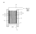
参考例1は、空気が、複数の固体酸化物燃料電池セルの各々のカソード電極層に、そして、燃料が、各々のアノード電極層に夫々個別に供給される場合である。参考例1の固体酸化物型燃料電池が、図1に示されている。 Reference Example 1 is a case where air is supplied individually to each cathode electrode layer of a plurality of solid oxide fuel cells, and fuel is supplied individually to each anode electrode layer. The solid oxide fuel cell of Reference Example 1 is shown in FIG.
図1に示された固体酸化物型燃料電池では、図8に示された固体酸化物燃料電池セルの複数枚が積層されており、同じ部分には、同じ符号が付されている。同図では、同じ矩形形状に形成された5枚の固体酸化物燃料電池セルC1乃至C5が、垂直配置されるように、断熱材層からなる筒状壁体11内に収納されている。燃料電池セルの枚数は、5枚に限られず、一枚又は複数とすることができ、取り出せる出力の電圧値又は電流値の大きさに合わせて選択される。
In the solid oxide fuel cell shown in FIG. 1, a plurality of the solid oxide fuel cells shown in FIG. 8 are stacked, and the same parts are denoted by the same reference numerals. In the figure, five solid oxide fuel cells C1 to C5 formed in the same rectangular shape are accommodated in a
参考例1では、空気と燃料が、固体酸化物燃料電池セルのカソード電極層とアノード電極層とに夫々個別に供給されるように、固体酸化物燃料電池セル間に、板状のセパレータ層14が挿入されている。固体酸化物燃料電池セルC1乃至C5とセパレータ層とで、固体酸化物燃料電池セル群が構成され、この固体酸化物燃料電池セル群の両側には、集電層12及び13が配置されている。筒状壁体11は、固体酸化物燃料電池セル群を取り囲んで収納し、固体酸化物燃料電池セル群の上端と下端とに空間を形成している。なお、両側に設けられた集電層は、固体酸化物燃料電池セル群の出力を取り出すためのものである。
In Reference Example 1 , a plate-shaped separator layer 14 is provided between the solid oxide fuel cells so that air and fuel are separately supplied to the cathode electrode layer and the anode electrode layer of the solid oxide fuel cells, respectively. Has been inserted. The solid oxide fuel cells C1 to C5 and the separator layer constitute a solid oxide fuel cell group, and current collecting layers 12 and 13 are arranged on both sides of the solid oxide fuel cell group. . The
固体酸化物燃料電池セル群の上端に形成された空間には、燃料Fと空気Goの供給装置が設けられる。各々の固体酸化物燃料電池セルC1乃至C5のアノード電極層3のみに燃料Fを供給する燃料供給装置15が設けられる。そして、空気供給装置16が、固体酸化物燃料電池セル群の上端の空間を覆うように設けられる。各アノード電極層3には、その上端から下端に向けて燃料Fが供給され、アノード電極層側を燃料リッチ状態とし、また、各カソード電極層2には、その上端から下端に向けて空気Goが供給され、カソード電極層側を酸素リッチ状態としている。
In the space formed at the upper end of the solid oxide fuel cell group, a supply device for the fuel F and the air Go is provided. A
固体酸化物燃料電池セル群に挿入されているセパレータ層14は、各個体酸化物燃料電池セルにおいて、燃料リッチ状態と酸素リッチ状態を区別して生成するものであり、セパレータ層14は、導電性材料又は電気絶縁性材料で形成される。導電性材料で形成された場合には、固体酸化物燃料電池セルC1乃至C5が直列接続されることになり、電気絶縁性材料で形成された場合には、リード線L1とL2により、固体酸化物燃料電池セルC1乃至C5を並列接続することもでき、或いは、直列接続することもできる。 The separator layer 14 inserted in the solid oxide fuel cell group is generated by distinguishing between the fuel-rich state and the oxygen-rich state in each solid oxide fuel cell, and the separator layer 14 is made of a conductive material. Alternatively, it is made of an electrically insulating material. When formed of a conductive material, the solid oxide fuel cells C1 to C5 are connected in series. When formed of an electrically insulating material, the solid oxide fuel cells C1 to C5 are connected by the lead wires L1 and L2. The physical fuel battery cells C1 to C5 can be connected in parallel or in series.
一方、固体酸化物燃料電池セル群の下端に形成された空間には、着火装置(図示なし)を有する燃焼装置17が設けられる。燃料電池を駆動するとき、この下端の空間に、固体酸化物燃料電池セルC1乃至C5のカソード電極層2を介して、空気Goが供給され、そして、アノード電極層3を介して燃料Fが供給されるので、燃焼装置17により、燃料Fが燃焼されて、火炎が生成される。この火炎によって、固体酸化物燃料電池セル群が発電駆動可能な温度にまで加熱される。
On the other hand, a
固体酸化物燃料電池セル群の発電開始後においては、固体酸化物燃料電池セル群で消費仕切れなかった燃料は、固体酸化物燃料電池セル群の下端から排出され、やはり、各カソード電極層2を通過して発電に寄与しなかった酸素もその下端から排出されるので、固体酸化物燃料電池セル群の排ガスは、燃焼装置17により安全に燃焼処理される。
After the start of power generation of the solid oxide fuel cell group, the fuel that is not partitioned by the solid oxide fuel cell group is discharged from the lower end of the solid oxide fuel cell group, and each
以上のように、参考例1の固体酸化物型燃料電池の構成によれば、固体酸化物燃料電池セル群の上端から空気及び燃料を供給し、固体酸化物燃料電池セル群の下端において、排ガスを燃焼するようにしたので、固体酸化物型燃料電池の容器を開放型にでき、その装置としての構成を簡単化でき、さらに、排ガスの燃焼による熱エネルギーを有効に利用することができる。しかも、排ガスを簡単に且つ安全に処理できる。 As described above, according to the configuration of the solid oxide fuel cell of Reference Example 1 , air and fuel are supplied from the upper end of the solid oxide fuel cell group, and the exhaust gas is discharged from the lower end of the solid oxide fuel cell group. Since the solid oxide fuel cell container can be opened, the configuration of the apparatus can be simplified, and the thermal energy from the combustion of exhaust gas can be used effectively. Moreover, the exhaust gas can be treated easily and safely.
参考例1は、空気と燃料が、固体酸化物燃料電池セルのカソード電極層とアノード電極層とに夫々個別に供給される場合であったが、参考例2では、空気と燃料との混合ガスが、固体酸化物燃料電池セル群に供給される固体酸化物型燃料電池の場合である。参考例2による固体酸化物型燃料電池の構成が、図2に示される。 Reference Example 1 was a case where air and fuel were separately supplied to the cathode electrode layer and the anode electrode layer of the solid oxide fuel cell, respectively. In Reference Example 2 , a mixed gas of air and fuel was used. This is the case of the solid oxide fuel cell supplied to the solid oxide fuel cell group. The configuration of the solid oxide fuel cell according to Reference Example 2 is shown in FIG.
図2に示された固体酸化物型燃料電池も、参考例1の場合と同様に、同じ矩形形状に形成された5枚の固体酸化物燃料電池セルC1乃至C5が、垂直配置されるように、断熱材層からなる筒状壁体11内に収納されている。なお、参考例2の固体酸化物型燃料電池では、参考例1の場合と異なり、固体酸化物燃料電池セル群には、混合ガスが供給されるので、固体酸化物燃料電池セル間にセパレート層を挿入する必要がなく、従って、固体酸化物燃料電池セルのカソード電極層又はアノード電極層と、隣接する固体酸化物燃料電池セルのアノード電極層又はカソード電極層とが面接触している。
As in the case of Reference Example 1 , the solid oxide fuel cell shown in FIG. 2 is also arranged so that five solid oxide fuel cells C1 to C5 formed in the same rectangular shape are arranged vertically. The
固体酸化物燃料電池セルC1乃至C5で固体酸化物燃料電池セル群が構成され、この固体酸化物燃料電池セル群が、筒状壁体11で取り囲まれる。筒状壁体11によって固体酸化物燃料電池セル群の上端に形成された空間には、混合ガス供給装置18が設けられ、固体酸化物燃料電池セル群の上端から、混合ガスが供給される。供給された混合ガスは、各固体酸化物燃料電池セルのカソード電極層2とアノード電極層3を通過する。
The solid oxide fuel cells C1 to C5 constitute a solid oxide fuel cell group, and the solid oxide fuel cell group is surrounded by the
各固体酸化物燃料電池セルのカソード電極層2とアノード電極層3を通過した混合ガスは、固体酸化物燃料電池セル群の下端に形成された空間に排出され、この空間で、燃焼装置17により燃焼される。また、燃料電池の発電において消費仕切れなかった燃料及び酸素も、固体酸化物燃料電池セル群の下端から排出されて、燃焼装置17により燃焼される。
The mixed gas that has passed through the
燃料電池を駆動するとき、この下端の空間に、固体酸化物燃料電池セルC1乃至C5のカソード電極層2とアノード電極層3を介して混合ガスが供給されるので、燃焼装置17により、混合ガス中の燃料Fが空気Goで燃焼されて、火炎が生成される。この火炎によって、固体酸化物燃料電池セル群が発電駆動可能な温度にまで加熱される。
When the fuel cell is driven, the mixed gas is supplied to the space at the lower end via the
固体酸化物燃料電池セル群の発電開始後においては、固体酸化物燃料電池セル群で消費仕切れなかった燃料は、固体酸化物燃料電池セル群の下端から排出され、同時に、発電に寄与しなかった酸素もその下端から排出されるので、固体酸化物燃料電池セル群の排ガスは、燃焼装置17により安全に燃焼処理される。
After the start of power generation of the solid oxide fuel cell group, the fuel that was not partitioned by the solid oxide fuel cell group was discharged from the lower end of the solid oxide fuel cell group, and at the same time, did not contribute to power generation Since oxygen is also discharged from the lower end, the exhaust gas of the solid oxide fuel cell group is safely burned by the
以上のように、参考例2の固体酸化物型燃料電池の構成によれば、固体酸化物燃料電池セル群の上端から混合ガスを供給し、固体酸化物燃料電池セル群の下端において、排ガスを燃焼するようにしたので、固体酸化物型燃料電池の容器を開放型にでき、その装置としての構成を簡単化できる。さらに、排ガスの燃焼による熱エネルギーを有効に利用することができ、しかも、排ガスを簡単に且つ安全に処理できる。 As described above, according to the configuration of the solid oxide fuel cell of Reference Example 2 , the mixed gas is supplied from the upper end of the solid oxide fuel cell group, and the exhaust gas is discharged at the lower end of the solid oxide fuel cell group. Since the combustion is performed, the container of the solid oxide fuel cell can be opened, and the configuration as the apparatus can be simplified. Furthermore, it is possible to effectively use the heat energy generated by the combustion of the exhaust gas, and to easily and safely treat the exhaust gas.
参考例2は、空気と燃料との混合ガスが、固体酸化物燃料電池セル群に供給される固体酸化物型燃料電池の場合であって、固体酸化物燃料電池セルのカソード電極層又はアノード電極層と、隣接する固体酸化物燃料電池セルのアノード電極層又はカソード電極層とが面接触している。しかし、カソード電極層とアノード電極層とが面接触しているため、接触抵抗が発生し、燃料電池セルの発電に対する集電効率が低下する可能性がある。さらに、カソード電極層とアノード電極層への混合ガスの供給が、その全面に渡って効率的に供給できないため、発電効率の向上に限界があった。 Reference Example 2 is a case of a solid oxide fuel cell in which a mixed gas of air and fuel is supplied to a solid oxide fuel cell group, and the cathode electrode layer or anode electrode of the solid oxide fuel cell The layer and the anode electrode layer or cathode electrode layer of the adjacent solid oxide fuel cell are in surface contact. However, since the cathode electrode layer and the anode electrode layer are in surface contact, contact resistance is generated, and there is a possibility that the current collection efficiency for power generation of the fuel cell decreases. Furthermore, since the supply of the mixed gas to the cathode electrode layer and the anode electrode layer cannot be efficiently supplied over the entire surface, there has been a limit in improving the power generation efficiency.
そこで、実施例1の固体酸化物型燃料電池は、図2に示された参考例2による固体酸化物型燃料電池の構成と同様であるが、積層配置された固体酸化物燃料電池セルC1乃至C5の各々の間に、ガス透過性の導電層を挿入することとした。図3に、そのガス透過性導電体層が固体酸化物燃料電池セル間に挿入された固体酸化物燃料電池セル群の一部が示されている。図2に示された固体酸化物燃料電池セル群と同じ部分には、同じ符号が付与されている。 Therefore, the solid oxide fuel cell of Example 1 has the same configuration as that of the solid oxide fuel cell according to Reference Example 2 shown in FIG. 2, but the stacked solid oxide fuel cells C1 to C1 are arranged. A gas-permeable conductive layer was inserted between each of C5. FIG. 3 shows a part of the solid oxide fuel cell group in which the gas permeable conductor layer is inserted between the solid oxide fuel cells. The same parts as those in the solid oxide fuel cell group shown in FIG.
固体酸化物燃料電池セルの電極層と同じ形状を有するガス透過性導電体層19が、固体酸化物燃料電池セルのカソード電極層2と、それに隣接する固体酸化物燃料電池セルのアノード電極層3との間に挿入されている。各ガス透過性導電体層19は、混合ガスを固体酸化物燃料電池セル群の上端から下端まで混合ガスを供給できるように、金属又は導電性セラミックによる多孔体で形成することができる。
The gas
また、導電体層19は、金属又は導電性セラミックによる板体の両面に、その垂直方向に溝が形成されたものでもよく、又は、その垂直方向に直交する波形状に形成された板体であってもよい。或いは、導電体層19自体を、金属又はカーボンによる織物体で形成してもよい。
Further, the
以上のように、実施例1の固体酸化物型燃料電池の構成によれば、ガス透過性導電体層が固体酸化物燃料電池セル群内に挿入されており、混合ガスが固体酸化物燃料電池セル群の上端から有効に供給され、固体酸化物燃料電池セル群の下端において、排ガスを燃焼するようにしたので、固体酸化物型燃料電池の容器を開放型にでき、その装置としての構成を簡単化できるとともに、燃料電池発電効率を向上できる。さらに、排ガスの燃焼による熱エネルギーを有効に利用することができ、しかも、排ガスを簡単に且つ安全に処理できる。 As described above, according to the configuration of the solid oxide fuel cell of Example 1 , the gas permeable conductor layer is inserted into the solid oxide fuel cell group, and the mixed gas is the solid oxide fuel cell. Since the exhaust gas is effectively supplied from the upper end of the cell group and the exhaust gas is burned at the lower end of the solid oxide fuel cell group, the container of the solid oxide fuel cell can be opened, and the configuration as an apparatus thereof can be achieved. It can be simplified and the fuel cell power generation efficiency can be improved. Furthermore, it is possible to effectively use the heat energy generated by the combustion of the exhaust gas, and to easily and safely treat the exhaust gas.
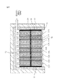
参考例2及び実施例1の固体酸化物型燃料電池では、筒状壁体内で、複数枚の固体酸化物燃料電池セルが積層され、一つの燃料電池セル群を構成していた。実施例2では、複数の燃料電池セル群を筒状壁体内に構成できるようにした。実施例2では、固体酸化物型燃料電池を複数の固体酸化物燃料電池セル群で構成するものとし、その実施例2の構成例が、図4に示される。 In the solid oxide fuel cells of Reference Example 2 and Example 1 , a plurality of solid oxide fuel cells were stacked in a cylindrical wall to constitute one fuel cell group. In Example 2 , a plurality of fuel battery cell groups can be configured in the cylindrical wall. In Example 2 , it is assumed that the solid oxide fuel cell is composed of a plurality of solid oxide fuel cell groups, and a configuration example of Example 2 is shown in FIG.
図4に示された固体酸化物型燃料電池では、2つの固体酸化物燃料電池セル群が構成されている。この固体酸化物燃料電池セル群は、図3に示された実施例1による固体酸化物燃料電池セル群で構成されており、各々の燃料電池セル群は、複数の固体酸化物燃料電池せるC11乃至C15の積層体と、複数の固体酸化物燃料電池セルC21乃至C25の積層体で構成されている。各固体酸化物燃料電池セルの間には、ガス透過性の導電体層19が挿入されている。
In the solid oxide fuel cell shown in FIG. 4, two solid oxide fuel cell groups are configured. This solid oxide fuel cell group is composed of the solid oxide fuel cell group according to Example 1 shown in FIG. 3, and each fuel cell group includes a plurality of solid oxide fuel cells C11. To C15 and a plurality of solid oxide fuel cells C21 to C25. A gas
この様に構成された2つの固体酸化物燃料電池セル群は、筒状壁体11内に取り囲まれるようにして収納される。2つの固体酸化物燃料電池セル群の間には、図5に示される電気絶縁性介在層20が配置され、2つの固体酸化物燃料電池セル群を電気的に分離している。図4では、固体酸化物燃料電池セル群が2つの場合を例にしたが、さらに多くの固体酸化物燃料電池セル群を収納してもよい。なお、固体酸化物燃料電池セル群として、ガス透過性導電体層を有しない参考例2の固体酸化物燃料電池セル群を採用してもよい。
The two solid oxide fuel cell groups configured in this way are housed so as to be surrounded by the
図5に示されるように、電気絶縁性介在層20は、電気絶縁性基板201と、導電体層202、203とを有している。この電気絶縁性介在層20は、固体酸化物燃料電池セルと同じ形状に形成される。ここで、電気絶縁性基板201が、2つの固体酸化物燃料電池セル群を電気的に分離する役割を持っているが、2つの固体酸化物燃料電池セル群からの集電を容易にするために、電気絶縁性基板201の両側に、導電体層202と203とが配置されている。2つの固体酸化物燃料電池セル群の電気出力を、並列接続することができる。
As shown in FIG. 5, the electrically insulating intervening
電気絶縁性介在層20を間に配置された2つの固体酸化物燃料電池セル群は、図4に示されるように、筒状壁体11内で積層されて収納され、2つの固体酸化物燃料電池セル群の上側と下側とに空間が形成される。その上側の空間には、混合ガス供給装置18が設けられ、混合ガスが2つの固体酸化物燃料電池セル群に同時に供給される。個々の固体酸化物燃料電池セルに上端から混合ガスが供給される。
As shown in FIG. 4, the two solid oxide fuel cell groups disposed between the electrically insulating intervening layers 20 are stacked and accommodated in the
筒状壁体11内であって、2つの固体酸化物燃料電池セル群の下側に形成された空間には、着火装置(図示なし)を含む燃焼装置17が配置され、この空間において、各固体酸化物燃料電池セルを通過してきた排ガス又は混合ガスが燃焼されて、火炎が生成される。図4の固体酸化物型燃料電池では、均一な火炎が生成されるように、電気絶縁性多孔体層21が、2つの固体酸化物燃料電池セル群の下端全面を覆うように配置されている。
A
燃料電池を駆動するとき、この下端の空間には、各固体酸化物燃料電池セル群のカソード電極層2とアノード電極層3を介して混合ガスが供給されるので、燃焼装置17により、混合ガス中の燃料Fが空気Goで燃焼されて、火炎が生成される。この火炎によって、固体酸化物燃料電池セル群が発電駆動可能な温度にまで加熱される。
When the fuel cell is driven, a mixed gas is supplied to the space at the lower end via the
また、固体酸化物燃料電池セル群の発電開始後においては、固体酸化物燃料電池セル群で消費仕切れなかった燃料が、固体酸化物燃料電池セル群の下端から排出され、同時に、発電に寄与しなかった酸素もその下端から排出されるので、固体酸化物燃料電池セル群の排ガスは、燃焼装置17により安全に燃焼処理される。
In addition, after the start of power generation of the solid oxide fuel cell group, the fuel that is not partitioned by the solid oxide fuel cell group is discharged from the lower end of the solid oxide fuel cell group and contributes to power generation at the same time. Oxygen that has not been exhausted is also discharged from its lower end, so that the exhaust gas of the solid oxide fuel cell group is safely burned by the
なお、固体酸化物型燃料電池の筒状壁体11の外側には、図4に示されるように、冷却装置22が設けられる。この冷却装置22は、例えば、水などの冷却媒体を流通できるパイプであり、このパイプが筒状壁体11の周囲に配設される。この冷却装置22によって、固体酸化物燃料電池セル群の発電時の熱が、冷却媒体で熱交換され、この熱が、装置外部に取り出されて利用される。
As shown in FIG. 4, a
以上のように、実施例2の固体酸化物型燃料電池の構成によれば、実施例1の場合と同様の効果を奏することに加えて、電気絶縁性介在層を固体酸化物燃料電池セル群の間に配置するようにしたので、固体酸化物燃料電池セル群の並列接続を簡単にできる。 As described above, according to the configuration of the solid oxide fuel cell of Example 2 , in addition to the same effects as those of Example 1 , the electrically insulating intervening layer is formed of the solid oxide fuel cell group. Therefore, it is possible to easily connect the solid oxide fuel cell groups in parallel.
実施例2では、複数の燃料電池セル群の間に電気絶縁性介在層を配置して、筒状壁体内に、各燃料電池セル群が電気絶縁性介在層を介して積み重ねられていた。そこで、実施例3では、複数の固体酸化物燃料電池セル群の各々の上下間に、電気絶縁性多孔体層を挟んで構成して、固体酸化物型燃料電池とするものとし、その実施例3の構成例が、図6に示される。 In Example 2 , an electrically insulative intervening layer was disposed between a plurality of fuel cell groups, and each fuel cell group was stacked in the cylindrical wall body via the insulative intervening layer. Therefore, in Example 3 , a solid oxide fuel cell is formed by sandwiching an electrically insulating porous body layer between the upper and lower sides of each of a plurality of solid oxide fuel cell groups. A configuration example of 3 is shown in FIG.
図6に示された固体酸化物型燃料電池では、2つの固体酸化物燃料電池セル群が構成されている。固体酸化物燃料電池セル群の各々は、図3に示された実施例1による固体酸化物燃料電池セル群と同様の構成の仕方であり、積層された複数の固体酸化物燃料電池セルC11乃至C18で、上段の第1固体酸化物燃料電池セル群が構成され、積層された複数の固体酸化物燃料電池セルC21乃至C28で、下段の第2固体酸化物燃料電池セル群が構成されている。積層された固体酸化物燃料電池セルの間には、ガス透過性の導電体層19が挿入されている。
In the solid oxide fuel cell shown in FIG. 6, two solid oxide fuel cell groups are configured. Each of the solid oxide fuel cell groups has a configuration similar to that of the solid oxide fuel cell group according to the first embodiment shown in FIG. 3, and includes a plurality of stacked solid oxide fuel cell cells C11 to C11. In C18, an upper first solid oxide fuel cell group is configured, and a plurality of stacked solid oxide fuel cells C21 to C28 form a lower second solid oxide fuel cell group. . A gas
第1固体酸化物燃料電池セル群と第2固体酸化物燃料電池セル群との間には、垂直に配置された固体酸化物燃料電池セルと直交する方向に広がる電気絶縁性多孔体層23が配置され、図6に示されるように、電気絶縁性多孔体層23の上面は、第1固体酸化物燃料電池セル群の下端面に接し、電気絶縁性多孔体層23の下面は、第2固体酸化物燃料電池セル群の上端面に接している。
Between the first solid oxide fuel cell group and the second solid oxide fuel cell group, there is an electrically insulating
筒状壁体11内において、第1固体酸化物燃料電池セル群と第2固体酸化物燃料電池セル群とが、集電層12及び13を介して収納される。この集電層12及び13が、第1及び第2固体酸化物燃料電池セル群を電気的に並列接続している。第1固体酸化物燃料電池セル群の上側と、第2固体酸化物燃料電池セル群の下側とに、夫々、空間が形成される。その上側の空間には、混合ガス供給装置18が設けられる。混合ガスが第1固体酸化物燃料電池セル群の上端に供給され、個々の固体酸化物燃料電池セルに上端から混合ガスが供給される。
In the
筒状壁体11内であって、第2固体酸化物燃料電池セル群の下側に形成された空間には、着火装置(図示なし)を含む燃焼装置17が配置される。この下側の空間では、第1固体酸化物燃料電池セル群、電気絶縁性多孔体層23、そして、第2固体酸化物燃料電池セル群を通過して排出された排ガス又は混合ガスが燃焼されて、火炎が生成される。図6の固体酸化物型燃料電池においても、実施例2と同様に、第2固体酸化物燃料電池セル群の下端面に、電気絶縁性多孔体層を配置してもよい。
A
燃料電池を駆動するとき、この下端の空間には、上段と下段における各固体酸化物燃料電池セル群のカソード電極層2とアノード電極層3を介して混合ガスが供給されるので、燃焼装置17により、混合ガス中の燃料Fが空気Goで燃焼されて、火炎が生成される。この火炎によって、第1及び第2固体酸化物燃料電池セル群が発電駆動可能な温度にまで加熱される。
When driving the fuel cell, the lower end space is supplied with the mixed gas through the
また、第1及び第2固体酸化物燃料電池セル群の発電開始後においては、固体酸化物燃料電池セル群で消費仕切れなかった燃料が、第2固体酸化物燃料電池セル群の下端から排出され、同時に、発電に寄与しなかった酸素もその下端から排出されるので、第1及び第2固体酸化物燃料電池セル群の排ガスは、燃焼装置17により安全に燃焼処理される。
In addition, after power generation of the first and second solid oxide fuel cell groups is started, fuel that is not partitioned by the solid oxide fuel cell group is discharged from the lower end of the second solid oxide fuel cell group. At the same time, oxygen that has not contributed to power generation is also discharged from the lower end thereof, so that the exhaust gas of the first and second solid oxide fuel cell groups is safely burned by the
なお、実施例3においても、固体酸化物型燃料電池の筒状壁体11の外側に、図6に示されるように、冷却装置22が設けられる。この冷却装置22は、例えば、水などの冷却媒体を流通できるパイプであり、このパイプが筒状壁体11の周囲に配設される。この冷却装置22によって、第1及び第2固体酸化物燃料電池セル群の発電時の熱が、冷却媒体で熱交換され、この熱が、装置外部に取り出されて利用される。
Also in Example 3 , as shown in FIG. 6, a
以上のように、実施例3の固体酸化物型燃料電池の構成によれば、実施例1の場合と同様の効果を奏することに加えて、電気絶縁性多孔体層を上段と下段の固体酸化物燃料電池セル群の間に配置するようにしたので、固体酸化物燃料電池セル群の並列接続を簡単にでき、電気絶縁性多孔体層を介して、更に複数段の固体酸化物燃料電池セル群を収納でき、燃料電池の出力容量を簡単に増加することができる。 As described above, according to the configuration of the solid oxide fuel cell of Example 3 , in addition to the same effects as those of Example 1 , the electrically insulating porous body layers are formed in the upper and lower solid oxide layers. Since it is arranged between the physical fuel cell groups, the parallel connection of the solid oxide fuel cell groups can be simplified, and a plurality of solid oxide fuel cell cells are further provided via the electrically insulating porous layer. Groups can be stored and the output capacity of the fuel cell can be increased easily.
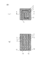
参考例2及び実施例1乃至3の固体酸化物型燃料電池では、基本的には、図8に示されるように、例えば、矩形形状に形成された平板の固体酸化物燃料電池セルが採用され、この固体酸化物燃料電池セルが複数積層された固体酸化物燃料電池セル群を構成していた。実施例3では、複数枚の固体酸化物燃料電池セルを積層するのではなく、一枚の矩形形状の固体酸化物燃料電池セルを、垂直軸を中心にして巻いた巻体の形式に形成するようにした。図7に、実施例4による固体酸化物型燃料電池を構成する巻体形式の固体酸化物燃料電池セルの形成例が示される。図7(a)には、一つの巻体形式の固体酸化物燃料電池セルに関する上面図が示され、図7(b)には、図7(a)に示されたX−X線における縦断面図が示されている。 In the solid oxide fuel cells of Reference Example 2 and Examples 1 to 3 , basically, for example, a flat solid oxide fuel cell formed in a rectangular shape is employed as shown in FIG. Thus, a solid oxide fuel cell group in which a plurality of the solid oxide fuel cells are stacked is configured. In Example 3 , instead of stacking a plurality of solid oxide fuel cells, a single rectangular solid oxide fuel cell is formed in the form of a roll wound around a vertical axis. I did it. FIG. 7 shows an example of forming a wound solid oxide fuel cell constituting the solid oxide fuel cell according to the fourth embodiment. FIG. 7A shows a top view of a solid oxide fuel cell of one roll type, and FIG. 7B shows a longitudinal section taken along line XX shown in FIG. 7A. A front view is shown.
固体酸化物燃料電池セルCが、固体酸化物基板1、カソード電極層2及びアノード電極層3を有する点では、図8に示された固体酸化物燃料電池セルと同様であるが、固体酸化物基板1、カソード電極層2及びアノード電極層3が重ねられた一枚の矩形形状の固体酸化物燃料電池セルが、垂直軸を中心にして巻かれ、渦巻状の巻体に形成される。このとき、図7では、カソード電極層2が外側になるように巻かれているが、アノード電極層3が外側になるように巻かれてもよい。ここで、巻体形式に巻かれる固体酸化物燃料電池セル自体を、固体酸化物基板1とカソード電極層2及びアノード電極層3とを有する固体酸化物燃料電池セルによる複数枚の積層体で形成してもよい。
The solid oxide fuel cell C is the same as the solid oxide fuel cell shown in FIG. 8 in that the solid oxide fuel cell C includes the
また、図7(a)に示されるように、渦巻きの外形が、矩形であると、例えば、他の実施例で用いられているような、矩形の箱体に形成された筒状壁体11内に収納する場合には、都合がよく、そして、複数の固体酸化物燃料電池セルCを垂直に収納することもできる。一方、その渦巻きの外形が、円形である場合には、固体酸化物燃料電池セルCを収納する筒状壁体の横断面形状も円形とする必要がある。
Further, as shown in FIG. 7A, when the outer shape of the spiral is rectangular, for example, a
なお、カソード電極層2の外面に集電層12を、更に、アノード電極層3の外面に集電層13を設けておくと、燃料電池として発電出力を有効に取り出せる。この集電層としては、上述したように、各電極層に埋め込まれるメッシュ状金属又はワイヤ状金属を使用することができる。また、固体酸化物燃料電池セルCが渦巻状に形成されたとき、カソード電極層2とアノード電極層3とが接触しないように、カソード電極層2とアノード電極層3との間に電気絶縁性多孔体層を形成する。
If a
さらに、筒状壁体11内に、渦巻き形状に巻かれて形成された固体酸化物燃料電池セルCの複数を並行に配置する場合には、その複数の固体酸化物燃料電池セルCの全てについて、カソード電極層、アノード電極層のいずれかを外側にして巻かれた巻体で構成するか、或いは、カソード電極層を外側にした巻体とアノード電極層を外側にした巻体を一組にして構成することができる。
Further, in the case where a plurality of solid oxide fuel cells C formed in a spiral shape are arranged in parallel in the
複数の固体酸化物燃料電池セルCの全てが、カソード電極層、アノード電極層のいずれかを外側にして巻かれた巻体で構成されると、各固体酸化物燃料電池セルが並列に接続されたことになり、カソード電極層を外側にした巻体とアノード電極層を外側にした巻体を一組にして構成した場合には、2つの固体酸化物燃料電池セルが直列に接続されたことになる。 When all of the plurality of solid oxide fuel cells C are formed of a wound body with either the cathode electrode layer or the anode electrode layer facing outside, the solid oxide fuel cells are connected in parallel. Therefore, when the winding body with the cathode electrode layer on the outside and the winding body with the anode electrode layer on the outside were configured as one set, the two solid oxide fuel cells were connected in series. become.
以上のように構成された固体酸化物燃料電池セルCは、参考例2及び実施例1乃至3の場合と同様に、筒状壁体11内に、垂直に配置されて収納され、固体酸化物燃料電池セルCの上側に形成された空間に、混合ガス供給装置18により混合ガスが供給される。一方、固体酸化物燃料電池セルCの下側に形成された空間では、固体酸化物燃料電池セルCから排出される混合ガス及び排ガスが燃焼されて、火炎が生成される。
The solid oxide fuel cell C configured as described above is disposed vertically in the
以上のように、実施例4の固体酸化物型燃料電池の構成によれば、参考例2及び実施例1乃至3の場合と同様に、固体酸化物型燃料電池の容器を開放型にでき、その装置としての構成を簡単化でき、さらに、排ガスの燃焼による熱エネルギーを有効に利用することができる。しかも、排ガスを簡単に且つ安全に処理できる。 As described above, according to the configuration of the solid oxide fuel cell of Example 4 , the container of the solid oxide fuel cell can be opened as in Reference Example 2 and Examples 1 to 3 , The configuration of the apparatus can be simplified, and furthermore, the thermal energy from the combustion of exhaust gas can be used effectively. Moreover, the exhaust gas can be treated easily and safely.
1 固体酸化物基板
2 カソード電極層
3 アノード電極層
4、11 筒状壁体
12、13 集電層
14 セパレート層
15 燃料供給装置
16 空気供給装置
17 燃焼空間部
18 混合ガス供給装置
19 ガス透過性導電層
20 電気絶縁性介在層
21、23 電気絶縁性多孔体層
22 冷却装置
DESCRIPTION OF
Claims (9)
前記各面を垂直にして前記固体酸化物燃料電池セルを囲んで収納する収納部を有する筒状壁体と、
前記収納部の上側から前記固体酸化物燃料電池セルに空気及び燃料を供給する供給装置と、
前記固体酸化物燃料電池セルの下端から排出される排ガスを前記収納部の下側で燃焼し、前記固体酸化物燃料電池セルを加熱する燃焼装置と、
を備え、
前記供給装置は、前記固体酸化物燃料電池セルの上端から、前記空気及び前記燃料の混合ガスを供給し、
前記固体酸化物燃料電池セルは、ガス透過性の導電体層を介在して積層され、
前記導電体層は、金属又は導電性セラミックによる多孔体であり、
前記導電体層は、前記金属又は前記導電性セラミックによる板体の両面において、前記固体酸化物燃料電池セルの前記上端から前記下端へ向かう方向である垂直方向に形成された溝を有することを特徴とする固体酸化物型燃料電池。 A solid oxide fuel cell having a solid oxide substrate, a porous cathode electrode layer formed on one surface of the substrate, and a porous anode electrode layer formed on the opposite surface opposite to the surface When,
A cylindrical wall body having a storage portion for storing each of the surfaces so as to surround each of the solid oxide fuel cells,
A supply device for supplying air and fuel to the solid oxide fuel cell from above the housing;
A combustion device that burns exhaust gas discharged from a lower end of the solid oxide fuel cell under the storage unit and heats the solid oxide fuel cell;
With
The supply device supplies a mixed gas of the air and the fuel from an upper end of the solid oxide fuel cell,
The solid oxide fuel cell is laminated with a gas permeable conductor layer interposed therebetween,
The conductor layer is a porous body made of metal or conductive ceramic,
The conductor layer has grooves formed in a vertical direction, which is a direction from the upper end to the lower end of the solid oxide fuel cell, on both surfaces of the plate made of the metal or the conductive ceramic. Solid oxide fuel cell.
分けられた前記セル群の間には、電気絶縁性の介在層が挿入され、前記各セル群の出力が並列に接続されることを特徴とする請求項2〜4のいずれか一項に記載の固体酸化物型燃料電池。 The plurality of solid oxide fuel cells are divided into cell groups and stacked in the cylindrical wall,
Between the divided was the cell group, are inserted electrically insulating intervening layer is, the according to any one of claims 2-4 in which the output of each cell group, characterized in that it is connected in parallel Solid oxide fuel cell.
前記各セル群の出力が並列に接続されることを特徴とする請求項2〜4のいずれか一項に記載の固体酸化物型燃料電池。 The plurality of solid oxide fuel cells are divided into cell groups in the vertical direction through an electrically insulating porous body layer and stacked in the cylindrical wall body,
The solid oxide fuel cell according to any one of claims 2 to 4 , wherein outputs of the respective cell groups are connected in parallel.
前記排ガスが、前記燃焼装置には、前記電気絶縁層を介して前記燃焼装置に供給されることを特徴とする請求項2〜6のいずれか一項に記載の固体酸化物型燃料電池。 An electrically insulating porous layer is formed on the lower end surface of the storage portion,
The solid oxide fuel cell according to any one of claims 2 to 6 , wherein the exhaust gas is supplied to the combustion device via the electrical insulating layer.
Priority Applications (5)
| Application Number | Priority Date | Filing Date | Title |
|---|---|---|---|
| JP2005071645A JP4931357B2 (en) | 2005-03-14 | 2005-03-14 | Solid oxide fuel cell |
| CA002539126A CA2539126A1 (en) | 2005-03-14 | 2006-03-09 | Power generating apparatus using solid oxide fuel cell |
| EP06251289A EP1703576B1 (en) | 2005-03-14 | 2006-03-10 | Power generating apparatus using solid oxide fuel cell |
| DE602006016361T DE602006016361D1 (en) | 2005-03-14 | 2006-03-10 | Energy generating device with solid oxide fuel cell |
| US11/372,832 US7659021B2 (en) | 2005-03-14 | 2006-03-10 | Power generating apparatus using solid oxide fuel cell |
Applications Claiming Priority (1)
| Application Number | Priority Date | Filing Date | Title |
|---|---|---|---|
| JP2005071645A JP4931357B2 (en) | 2005-03-14 | 2005-03-14 | Solid oxide fuel cell |
Publications (3)
| Publication Number | Publication Date |
|---|---|
| JP2006253090A JP2006253090A (en) | 2006-09-21 |
| JP2006253090A5 JP2006253090A5 (en) | 2008-01-31 |
| JP4931357B2 true JP4931357B2 (en) | 2012-05-16 |
Family
ID=36636616
Family Applications (1)
| Application Number | Title | Priority Date | Filing Date |
|---|---|---|---|
| JP2005071645A Expired - Fee Related JP4931357B2 (en) | 2005-03-14 | 2005-03-14 | Solid oxide fuel cell |
Country Status (5)
| Country | Link |
|---|---|
| US (1) | US7659021B2 (en) |
| EP (1) | EP1703576B1 (en) |
| JP (1) | JP4931357B2 (en) |
| CA (1) | CA2539126A1 (en) |
| DE (1) | DE602006016361D1 (en) |
Families Citing this family (27)
| Publication number | Priority date | Publication date | Assignee | Title |
|---|---|---|---|---|
| JP5013748B2 (en) | 2006-05-23 | 2012-08-29 | 新光電気工業株式会社 | Solid oxide fuel cell |
| JP5256598B2 (en) * | 2006-09-01 | 2013-08-07 | 大日本印刷株式会社 | Single-chamber solid oxide fuel cell and its stack structure |
| JP5011907B2 (en) * | 2006-09-25 | 2012-08-29 | 大日本印刷株式会社 | Stack jig and stack structure of single-chamber solid oxide fuel cell using the same |
| JP2008159448A (en) * | 2006-12-25 | 2008-07-10 | Shinko Electric Ind Co Ltd | Solid oxide fuel cell power generating device |
| JP5207019B2 (en) * | 2007-02-05 | 2013-06-12 | ソニー株式会社 | Polymer electrolyte fuel cell and electronic device equipped with the same |
| WO2008153763A1 (en) * | 2007-05-25 | 2008-12-18 | Massachusetts Institute Of Technology | Three dimensional single-chamber fuel cells |
| DE102007028299A1 (en) * | 2007-06-20 | 2008-12-24 | Daimler Ag | Fuel cell assembly with vented fuel cell housing |
| JP5243770B2 (en) * | 2007-10-30 | 2013-07-24 | 京セラ株式会社 | Fuel cell and portable electronic device |
| WO2010066466A1 (en) * | 2008-12-12 | 2010-06-17 | Ezelleron Gmbh | Fuel cell system with burner |
| JP5304385B2 (en) * | 2009-03-27 | 2013-10-02 | 大日本印刷株式会社 | Single-chamber solid oxide fuel cell |
| US20100310961A1 (en) * | 2009-06-06 | 2010-12-09 | Dr. Robert Daniel Clark | Integratable and Scalable Solid Oxide Fuel Cell Structure and Method of Forming |
| JP5435385B2 (en) | 2009-07-29 | 2014-03-05 | Tdk株式会社 | Solid oxide fuel cell and method for producing solid oxide fuel cell |
| US9118052B2 (en) | 2011-09-27 | 2015-08-25 | Philips 66 Company | Integrated natural gas powered SOFC systems |
| US9577297B2 (en) | 2011-09-30 | 2017-02-21 | General Electric Company | Electrochemical cells including a conductive matrix |
| JP5963494B2 (en) * | 2012-03-27 | 2016-08-03 | 大阪瓦斯株式会社 | Fuel cell device |
| US10418657B2 (en) | 2013-10-08 | 2019-09-17 | Phillips 66 Company | Formation of solid oxide fuel cells by spraying |
| WO2015054024A1 (en) | 2013-10-08 | 2015-04-16 | Phillips 66 Company | Gas phase modification of solid oxide fuel cells |
| WO2015054065A1 (en) | 2013-10-08 | 2015-04-16 | Phillips 66 Company | Liquid phase modification of electrodes of solid oxide fuel cells |
| US11239470B2 (en) | 2018-12-17 | 2022-02-01 | General Electric Company | Integrated fuel cell and combustion system |
| US11719441B2 (en) | 2022-01-04 | 2023-08-08 | General Electric Company | Systems and methods for providing output products to a combustion chamber of a gas turbine engine |
| US11794912B2 (en) | 2022-01-04 | 2023-10-24 | General Electric Company | Systems and methods for reducing emissions with a fuel cell |
| US11933216B2 (en) | 2022-01-04 | 2024-03-19 | General Electric Company | Systems and methods for providing output products to a combustion chamber of a gas turbine engine |
| US11804607B2 (en) | 2022-01-21 | 2023-10-31 | General Electric Company | Cooling of a fuel cell assembly |
| US11967743B2 (en) | 2022-02-21 | 2024-04-23 | General Electric Company | Modular fuel cell assembly |
| US11817700B1 (en) | 2022-07-20 | 2023-11-14 | General Electric Company | Decentralized electrical power allocation system |
| US11923586B1 (en) | 2022-11-10 | 2024-03-05 | General Electric Company | Gas turbine combustion section having an integrated fuel cell assembly |
| US11859820B1 (en) | 2022-11-10 | 2024-01-02 | General Electric Company | Gas turbine combustion section having an integrated fuel cell assembly |
Family Cites Families (13)
| Publication number | Priority date | Publication date | Assignee | Title |
|---|---|---|---|---|
| US4640875A (en) * | 1985-02-07 | 1987-02-03 | Westinghouse Electric Corp. | Fuel cell generator containing a gas sealing means |
| JPH03133065A (en) * | 1989-10-18 | 1991-06-06 | Agency Of Ind Science & Technol | Solid electrolyte fuel cell module |
| JP3259277B2 (en) * | 1991-01-21 | 2002-02-25 | 東陶機器株式会社 | Power generator incorporating a fuel cell |
| US5273837A (en) * | 1992-12-23 | 1993-12-28 | Corning Incorporated | Solid electrolyte fuel cells |
| WO2001073880A1 (en) | 2000-03-24 | 2001-10-04 | Scientific Generics Limited | Mixed reactant fuel cells |
| JP2002063916A (en) * | 2000-08-22 | 2002-02-28 | Mitsubishi Heavy Ind Ltd | Solid electrolyte fuel cell and module |
| DE10059892B4 (en) * | 2000-12-01 | 2010-04-08 | Stiebel Eltron Gmbh & Co. Kg | Method of operating a combined heat and power plant and combined heat and power plant |
| JP2002280053A (en) * | 2001-03-21 | 2002-09-27 | Toto Ltd | Fuel cell power generating system |
| JP3860733B2 (en) * | 2001-09-17 | 2006-12-20 | 新光電気工業株式会社 | Fuel cell |
| JP4227757B2 (en) * | 2002-04-02 | 2009-02-18 | 新光電気工業株式会社 | Fuel cell |
| JP4475861B2 (en) * | 2002-06-11 | 2010-06-09 | 三菱重工業株式会社 | Solid oxide fuel cell unit |
| JP4249960B2 (en) * | 2002-08-28 | 2009-04-08 | 新光電気工業株式会社 | Fuel cell |
| DE10321248A1 (en) * | 2003-05-12 | 2004-12-09 | Siemens Ag | connection |
-
2005
- 2005-03-14 JP JP2005071645A patent/JP4931357B2/en not_active Expired - Fee Related
-
2006
- 2006-03-09 CA CA002539126A patent/CA2539126A1/en not_active Abandoned
- 2006-03-10 US US11/372,832 patent/US7659021B2/en not_active Expired - Fee Related
- 2006-03-10 EP EP06251289A patent/EP1703576B1/en not_active Expired - Fee Related
- 2006-03-10 DE DE602006016361T patent/DE602006016361D1/en active Active
Also Published As
| Publication number | Publication date |
|---|---|
| US7659021B2 (en) | 2010-02-09 |
| CA2539126A1 (en) | 2006-09-14 |
| EP1703576A3 (en) | 2007-01-24 |
| EP1703576A2 (en) | 2006-09-20 |
| EP1703576B1 (en) | 2010-08-25 |
| DE602006016361D1 (en) | 2010-10-07 |
| US20060204809A1 (en) | 2006-09-14 |
| JP2006253090A (en) | 2006-09-21 |
Similar Documents
| Publication | Publication Date | Title |
|---|---|---|
| JP4931357B2 (en) | Solid oxide fuel cell | |
| JP5013748B2 (en) | Solid oxide fuel cell | |
| JP3860733B2 (en) | Fuel cell | |
| JP2006318767A (en) | Electrode material and fuel cell | |
| JP2004139936A (en) | Fuel battery | |
| JP4405196B2 (en) | Solid electrolyte fuel cell | |
| JP4227757B2 (en) | Fuel cell | |
| US7470480B2 (en) | Solid electrolyte fuel-cell device | |
| JP2009099267A (en) | Solid oxide fuel cell module | |
| JP5153062B2 (en) | Solid oxide fuel cell | |
| JP2007157336A (en) | Power generation device utilizing solid oxide fuel cell | |
| JP2007149548A (en) | Solid oxide type fuel cell and its manufacturing method | |
| JP2004172062A (en) | Fuel cell system and multilayer cell for the same | |
| JP4057822B2 (en) | Fuel cell, cell stack and fuel cell | |
| JP2005063692A (en) | Solid electrolyte fuel cell | |
| JP4953596B2 (en) | Solid oxide fuel cell power generator | |
| JP4256699B2 (en) | Fuel cell | |
| US20040067408A1 (en) | Fuel cell | |
| JP2004119270A (en) | Fuel cell | |
| JP6075766B2 (en) | Cell stack device, fuel cell module and fuel cell device | |
| JP2006253016A (en) | Solid oxide fuel cell device | |
| JP2005078808A (en) | Solid oxide surface utilization fuel battery | |
| JP2005071629A (en) | Solid electrolyte fuel battery | |
| JP2006185791A (en) | Fuel cell | |
| JP2006221879A (en) | Solid oxide electrolyte fuel cell |
Legal Events
| Date | Code | Title | Description |
|---|---|---|---|
| A521 | Written amendment |
Free format text: JAPANESE INTERMEDIATE CODE: A523 Effective date: 20071207 |
|
| A621 | Written request for application examination |
Free format text: JAPANESE INTERMEDIATE CODE: A621 Effective date: 20071207 |
|
| A977 | Report on retrieval |
Free format text: JAPANESE INTERMEDIATE CODE: A971007 Effective date: 20110316 |
|
| A131 | Notification of reasons for refusal |
Free format text: JAPANESE INTERMEDIATE CODE: A131 Effective date: 20110426 |
|
| A521 | Written amendment |
Free format text: JAPANESE INTERMEDIATE CODE: A523 Effective date: 20110624 |
|
| A02 | Decision of refusal |
Free format text: JAPANESE INTERMEDIATE CODE: A02 Effective date: 20110906 |
|
| A521 | Written amendment |
Free format text: JAPANESE INTERMEDIATE CODE: A523 Effective date: 20111031 |
|
| A911 | Transfer to examiner for re-examination before appeal (zenchi) |
Free format text: JAPANESE INTERMEDIATE CODE: A911 Effective date: 20111115 |
|
| A131 | Notification of reasons for refusal |
Free format text: JAPANESE INTERMEDIATE CODE: A131 Effective date: 20111213 |
|
| A521 | Written amendment |
Free format text: JAPANESE INTERMEDIATE CODE: A523 Effective date: 20111222 |
|
| TRDD | Decision of grant or rejection written | ||
| A01 | Written decision to grant a patent or to grant a registration (utility model) |
Free format text: JAPANESE INTERMEDIATE CODE: A01 Effective date: 20120117 |
|
| A01 | Written decision to grant a patent or to grant a registration (utility model) |
Free format text: JAPANESE INTERMEDIATE CODE: A01 |
|
| A61 | First payment of annual fees (during grant procedure) |
Free format text: JAPANESE INTERMEDIATE CODE: A61 Effective date: 20120214 |
|
| R150 | Certificate of patent or registration of utility model |
Ref document number: 4931357 Country of ref document: JP Free format text: JAPANESE INTERMEDIATE CODE: R150 Free format text: JAPANESE INTERMEDIATE CODE: R150 |
|
| FPAY | Renewal fee payment (event date is renewal date of database) |
Free format text: PAYMENT UNTIL: 20150224 Year of fee payment: 3 |
|
| LAPS | Cancellation because of no payment of annual fees |