JP4927315B2 - Method for hydroforming articles and articles formed thereby - Google Patents
Method for hydroforming articles and articles formed thereby Download PDFInfo
- Publication number
- JP4927315B2 JP4927315B2 JP2003549025A JP2003549025A JP4927315B2 JP 4927315 B2 JP4927315 B2 JP 4927315B2 JP 2003549025 A JP2003549025 A JP 2003549025A JP 2003549025 A JP2003549025 A JP 2003549025A JP 4927315 B2 JP4927315 B2 JP 4927315B2
- Authority
- JP
- Japan
- Prior art keywords
- adhesive
- hydroforming
- tube portion
- female
- tube
- Prior art date
- Legal status (The legal status is an assumption and is not a legal conclusion. Google has not performed a legal analysis and makes no representation as to the accuracy of the status listed.)
- Expired - Fee Related
Links
- 238000000034 method Methods 0.000 title claims description 26
- 239000000853 adhesive Substances 0.000 claims abstract description 71
- 230000001070 adhesive effect Effects 0.000 claims abstract description 71
- 229910052751 metal Inorganic materials 0.000 description 11
- 239000002184 metal Substances 0.000 description 11
- 238000010438 heat treatment Methods 0.000 description 8
- 238000002347 injection Methods 0.000 description 8
- 239000007924 injection Substances 0.000 description 8
- 238000004519 manufacturing process Methods 0.000 description 8
- XAGFODPZIPBFFR-UHFFFAOYSA-N aluminium Chemical compound [Al] XAGFODPZIPBFFR-UHFFFAOYSA-N 0.000 description 5
- 229910052782 aluminium Inorganic materials 0.000 description 4
- 229920006332 epoxy adhesive Polymers 0.000 description 4
- 239000000463 material Substances 0.000 description 4
- 229910000838 Al alloy Inorganic materials 0.000 description 3
- 229910000831 Steel Inorganic materials 0.000 description 3
- 239000003570 air Substances 0.000 description 3
- 230000006698 induction Effects 0.000 description 3
- 238000005065 mining Methods 0.000 description 3
- 239000000047 product Substances 0.000 description 3
- 239000010959 steel Substances 0.000 description 3
- XEEYBQQBJWHFJM-UHFFFAOYSA-N Iron Chemical compound [Fe] XEEYBQQBJWHFJM-UHFFFAOYSA-N 0.000 description 2
- 238000004140 cleaning Methods 0.000 description 2
- 238000005336 cracking Methods 0.000 description 2
- 238000005238 degreasing Methods 0.000 description 2
- 239000012530 fluid Substances 0.000 description 2
- 230000000704 physical effect Effects 0.000 description 2
- 230000009257 reactivity Effects 0.000 description 2
- 239000000243 solution Substances 0.000 description 2
- 230000003068 static effect Effects 0.000 description 2
- 238000003466 welding Methods 0.000 description 2
- 229910001335 Galvanized steel Inorganic materials 0.000 description 1
- 239000012080 ambient air Substances 0.000 description 1
- 230000015572 biosynthetic process Effects 0.000 description 1
- 239000003518 caustics Substances 0.000 description 1
- 239000007795 chemical reaction product Substances 0.000 description 1
- 238000010276 construction Methods 0.000 description 1
- 230000007547 defect Effects 0.000 description 1
- 230000001419 dependent effect Effects 0.000 description 1
- 238000007598 dipping method Methods 0.000 description 1
- 230000007613 environmental effect Effects 0.000 description 1
- 238000001125 extrusion Methods 0.000 description 1
- 239000008397 galvanized steel Substances 0.000 description 1
- 238000003780 insertion Methods 0.000 description 1
- 230000037431 insertion Effects 0.000 description 1
- 229910052742 iron Inorganic materials 0.000 description 1
- 238000005304 joining Methods 0.000 description 1
- 239000000203 mixture Substances 0.000 description 1
- 238000012986 modification Methods 0.000 description 1
- 230000004048 modification Effects 0.000 description 1
- 238000000465 moulding Methods 0.000 description 1
- 239000007787 solid Substances 0.000 description 1
- 239000002904 solvent Substances 0.000 description 1
- RYFMWSXOAZQYPI-UHFFFAOYSA-K trisodium phosphate Chemical compound [Na+].[Na+].[Na+].[O-]P([O-])([O-])=O RYFMWSXOAZQYPI-UHFFFAOYSA-K 0.000 description 1
- 230000000007 visual effect Effects 0.000 description 1
- 238000011179 visual inspection Methods 0.000 description 1
Images


Classifications
-
- B—PERFORMING OPERATIONS; TRANSPORTING
- B21—MECHANICAL METAL-WORKING WITHOUT ESSENTIALLY REMOVING MATERIAL; PUNCHING METAL
- B21D—WORKING OR PROCESSING OF SHEET METAL OR METAL TUBES, RODS OR PROFILES WITHOUT ESSENTIALLY REMOVING MATERIAL; PUNCHING METAL
- B21D26/00—Shaping without cutting otherwise than using rigid devices or tools or yieldable or resilient pads, i.e. applying fluid pressure or magnetic forces
- B21D26/02—Shaping without cutting otherwise than using rigid devices or tools or yieldable or resilient pads, i.e. applying fluid pressure or magnetic forces by applying fluid pressure
- B21D26/033—Deforming tubular bodies
-
- B—PERFORMING OPERATIONS; TRANSPORTING
- B21—MECHANICAL METAL-WORKING WITHOUT ESSENTIALLY REMOVING MATERIAL; PUNCHING METAL
- B21D—WORKING OR PROCESSING OF SHEET METAL OR METAL TUBES, RODS OR PROFILES WITHOUT ESSENTIALLY REMOVING MATERIAL; PUNCHING METAL
- B21D39/00—Application of procedures in order to connect objects or parts, e.g. coating with sheet metal otherwise than by plating; Tube expanders
- B21D39/04—Application of procedures in order to connect objects or parts, e.g. coating with sheet metal otherwise than by plating; Tube expanders of tubes with tubes; of tubes with rods
-
- B—PERFORMING OPERATIONS; TRANSPORTING
- B62—LAND VEHICLES FOR TRAVELLING OTHERWISE THAN ON RAILS
- B62D—MOTOR VEHICLES; TRAILERS
- B62D23/00—Combined superstructure and frame, i.e. monocoque constructions
- B62D23/005—Combined superstructure and frame, i.e. monocoque constructions with integrated chassis in the whole shell, e.g. meshwork, tubes, or the like
-
- B—PERFORMING OPERATIONS; TRANSPORTING
- B62—LAND VEHICLES FOR TRAVELLING OTHERWISE THAN ON RAILS
- B62D—MOTOR VEHICLES; TRAILERS
- B62D25/00—Superstructure or monocoque structure sub-units; Parts or details thereof not otherwise provided for
-
- B—PERFORMING OPERATIONS; TRANSPORTING
- B62—LAND VEHICLES FOR TRAVELLING OTHERWISE THAN ON RAILS
- B62D—MOTOR VEHICLES; TRAILERS
- B62D27/00—Connections between superstructure or understructure sub-units
- B62D27/02—Connections between superstructure or understructure sub-units rigid
- B62D27/026—Connections by glue bonding
-
- F—MECHANICAL ENGINEERING; LIGHTING; HEATING; WEAPONS; BLASTING
- F16—ENGINEERING ELEMENTS AND UNITS; GENERAL MEASURES FOR PRODUCING AND MAINTAINING EFFECTIVE FUNCTIONING OF MACHINES OR INSTALLATIONS; THERMAL INSULATION IN GENERAL
- F16B—DEVICES FOR FASTENING OR SECURING CONSTRUCTIONAL ELEMENTS OR MACHINE PARTS TOGETHER, e.g. NAILS, BOLTS, CIRCLIPS, CLAMPS, CLIPS OR WEDGES; JOINTS OR JOINTING
- F16B11/00—Connecting constructional elements or machine parts by sticking or pressing them together, e.g. cold pressure welding
- F16B11/006—Connecting constructional elements or machine parts by sticking or pressing them together, e.g. cold pressure welding by gluing
- F16B11/008—Connecting constructional elements or machine parts by sticking or pressing them together, e.g. cold pressure welding by gluing of tubular elements or rods in coaxial engagement
-
- Y—GENERAL TAGGING OF NEW TECHNOLOGICAL DEVELOPMENTS; GENERAL TAGGING OF CROSS-SECTIONAL TECHNOLOGIES SPANNING OVER SEVERAL SECTIONS OF THE IPC; TECHNICAL SUBJECTS COVERED BY FORMER USPC CROSS-REFERENCE ART COLLECTIONS [XRACs] AND DIGESTS
- Y10—TECHNICAL SUBJECTS COVERED BY FORMER USPC
- Y10T—TECHNICAL SUBJECTS COVERED BY FORMER US CLASSIFICATION
- Y10T156/00—Adhesive bonding and miscellaneous chemical manufacture
- Y10T156/10—Methods of surface bonding and/or assembly therefor
- Y10T156/1002—Methods of surface bonding and/or assembly therefor with permanent bending or reshaping or surface deformation of self sustaining lamina
- Y10T156/1043—Subsequent to assembly
-
- Y—GENERAL TAGGING OF NEW TECHNOLOGICAL DEVELOPMENTS; GENERAL TAGGING OF CROSS-SECTIONAL TECHNOLOGIES SPANNING OVER SEVERAL SECTIONS OF THE IPC; TECHNICAL SUBJECTS COVERED BY FORMER USPC CROSS-REFERENCE ART COLLECTIONS [XRACs] AND DIGESTS
- Y10—TECHNICAL SUBJECTS COVERED BY FORMER USPC
- Y10T—TECHNICAL SUBJECTS COVERED BY FORMER US CLASSIFICATION
- Y10T29/00—Metal working
- Y10T29/49—Method of mechanical manufacture
- Y10T29/49616—Structural member making
- Y10T29/49622—Vehicular structural member making
-
- Y—GENERAL TAGGING OF NEW TECHNOLOGICAL DEVELOPMENTS; GENERAL TAGGING OF CROSS-SECTIONAL TECHNOLOGIES SPANNING OVER SEVERAL SECTIONS OF THE IPC; TECHNICAL SUBJECTS COVERED BY FORMER USPC CROSS-REFERENCE ART COLLECTIONS [XRACs] AND DIGESTS
- Y10—TECHNICAL SUBJECTS COVERED BY FORMER USPC
- Y10T—TECHNICAL SUBJECTS COVERED BY FORMER US CLASSIFICATION
- Y10T29/00—Metal working
- Y10T29/49—Method of mechanical manufacture
- Y10T29/49616—Structural member making
- Y10T29/49623—Static structure, e.g., a building component
-
- Y—GENERAL TAGGING OF NEW TECHNOLOGICAL DEVELOPMENTS; GENERAL TAGGING OF CROSS-SECTIONAL TECHNOLOGIES SPANNING OVER SEVERAL SECTIONS OF THE IPC; TECHNICAL SUBJECTS COVERED BY FORMER USPC CROSS-REFERENCE ART COLLECTIONS [XRACs] AND DIGESTS
- Y10—TECHNICAL SUBJECTS COVERED BY FORMER USPC
- Y10T—TECHNICAL SUBJECTS COVERED BY FORMER US CLASSIFICATION
- Y10T29/00—Metal working
- Y10T29/49—Method of mechanical manufacture
- Y10T29/49805—Shaping by direct application of fluent pressure
-
- Y—GENERAL TAGGING OF NEW TECHNOLOGICAL DEVELOPMENTS; GENERAL TAGGING OF CROSS-SECTIONAL TECHNOLOGIES SPANNING OVER SEVERAL SECTIONS OF THE IPC; TECHNICAL SUBJECTS COVERED BY FORMER USPC CROSS-REFERENCE ART COLLECTIONS [XRACs] AND DIGESTS
- Y10—TECHNICAL SUBJECTS COVERED BY FORMER USPC
- Y10T—TECHNICAL SUBJECTS COVERED BY FORMER US CLASSIFICATION
- Y10T29/00—Metal working
- Y10T29/49—Method of mechanical manufacture
- Y10T29/49826—Assembling or joining
- Y10T29/49885—Assembling or joining with coating before or during assembling
-
- Y—GENERAL TAGGING OF NEW TECHNOLOGICAL DEVELOPMENTS; GENERAL TAGGING OF CROSS-SECTIONAL TECHNOLOGIES SPANNING OVER SEVERAL SECTIONS OF THE IPC; TECHNICAL SUBJECTS COVERED BY FORMER USPC CROSS-REFERENCE ART COLLECTIONS [XRACs] AND DIGESTS
- Y10—TECHNICAL SUBJECTS COVERED BY FORMER USPC
- Y10T—TECHNICAL SUBJECTS COVERED BY FORMER US CLASSIFICATION
- Y10T29/00—Metal working
- Y10T29/49—Method of mechanical manufacture
- Y10T29/4998—Combined manufacture including applying or shaping of fluent material
- Y10T29/49993—Filling of opening
Abstract
Description
本発明は、少なくとも2つの管状部材を、接合された部材を所望の形状にハイドロフォーミング(液圧成形)することができるように、ともに接合することに関する。より詳細には、本発明は、金属管の雄型セクションおよび雌型セクションを接着剤で接合する方法であって、接合されたセクションが、完成製品を形成するために、ハイドロフォーミング作業の応力に耐えることができる方法に関する。 The present invention relates to joining together at least two tubular members so that the joined members can be hydroformed into a desired shape. More particularly, the present invention is a method of bonding a male section and a female section of a metal tube with an adhesive, wherein the bonded sections are subjected to the stress of hydroforming operations to form a finished product. It relates to a method that can withstand.
歴史的に、自動車用フレームとしてシートメタルセクションが使用されている。自動車における比較的最近の開発の1つが、重量および費用を低減するための、従来のシートメタルフレームの代わりの管状フレームの使用である。したがって、さまざまな部品またはボディパネルを取付けることができる乗物用フレームを提供することが、自動車産業において知られている。そのようなフレームは、互いに連結されて管状セクションを形成する、いくつかの個別のストレート管状(パイプ)部材から形成することができる。これらの管状セクションは、予めハイドロフォーミング可能な(prehydroformable)バードケージを形成し、次に、最終形状にハイドロフォーミングすることができる。 Historically, sheet metal sections have been used as automobile frames. One relatively recent development in automobiles is the use of a tubular frame instead of a conventional sheet metal frame to reduce weight and cost. Accordingly, it is known in the automotive industry to provide a vehicle frame to which various parts or body panels can be attached. Such a frame can be formed from a number of individual straight tubular (pipe) members that are connected together to form a tubular section. These tubular sections can form a pre-hydroformable birdcage that can then be hydroformed to the final shape.
管状部材は、容易に入手可能であり、重量と強度との比が良好であることから有利である。結果として、そのような管状部材の使用は、経済的に有利である。これらの部材の最終形状は、元の管状構成から非常に大きく変わることができ、実際には、略矩形であることが多い。これらの管状部材は、過去において、しばしば、形状にスタンピングされたが、これらの管状セクションを最終形状に形成するための特に有利な1つの方法が、ハイドロフォーミングプロセスによる。 Tubular members are advantageous because they are readily available and have a good weight to strength ratio. As a result, the use of such tubular members is economically advantageous. The final shape of these members can vary greatly from the original tubular configuration and in practice is often substantially rectangular. While these tubular members have often been stamped into shape in the past, one particularly advantageous method for forming these tubular sections into a final shape is through a hydroforming process.
既知のハイドロフォーミングプロセスが、たとえば、特許文献1に加えて、特許文献2および特許文献3に特定されている。 Known hydroforming processes are specified in, for example, Patent Document 2 and Patent Document 3 in addition to Patent Document 1.
特許文献1は、ハイドロフォーミングされた空間フレームおよびその製造方法を開示している。個別のサイドレールが、ストレート管状ブランクから形成され、ストレート管状ブランクは、S字形に曲げられ、次に、正しい形状にハイドロフォーミングされ、フレームセクションの長さにわたって断面直径がさまざまである。個別のセクションは、ハイドロフォーミング作業前にともに突合せ溶接されて、より大きいセクションを形成し、これらは、ハイドロフォーミング作業後、接合される。 Patent Document 1 discloses a hydroformed space frame and a manufacturing method thereof. Individual side rails are formed from straight tubular blanks, which are bent into S-shapes and then hydroformed to the correct shape and vary in cross-sectional diameter over the length of the frame section. The individual sections are butt welded together before the hydroforming operation to form larger sections that are joined after the hydroforming operation.
特許文献2は、車両フレーム用のハイドロフォーミングされたサイドレールおよびその製造方法を開示している。この特許によれば、乗物フレーム用サイドレールは、エレメントの長さに沿って、さまざまな壁厚さおよび断面積を有する。サイドレールの個別の部分をハイドロフォーミングして、ハイドロフォーミング後、組合せてサイドレールにする。 Patent Literature 2 discloses a hydroformed side rail for a vehicle frame and a manufacturing method thereof. According to this patent, vehicle frame side rails have various wall thicknesses and cross-sectional areas along the length of the element. Hydroforming individual parts of the side rails and combining them into side rails after hydroforming.
特許文献3は、ハイドロフォーミングされた管状部材および管状部材をハイドロフォーミングする方法を開示している。管状部材は、この特許に教示されているように、管がハイドロフォーミングされるブランクのサイズを変えることによって、さまざまな円周、直径、およびゲージを有する最終製品に形成される。 Patent Document 3 discloses a hydroformed tubular member and a method of hydroforming the tubular member. Tubular members are formed into final products having various circumferences, diameters, and gauges by changing the size of the blank in which the tube is hydroformed, as taught in this patent.
一般に、ハイドロフォーミングプロセスでは、所望の最終形状のダイ内に管状アセンブリを配置し、管状ブランクの内部に加圧流体を導入することによって、管状アセンブリを所望の最終形状に形成する。加圧流体は、管状アセンブリをダイに適合するように成形して、最終構造を形成する。 Generally, in a hydroforming process, a tubular assembly is formed into a desired final shape by placing the tubular assembly in a die of the desired final shape and introducing a pressurized fluid into the interior of the tubular blank. The pressurized fluid shapes the tubular assembly to fit the die to form the final structure.
上記から、管部品間の連結が、確実であり、かつ、耐漏れ性であり、好ましくは漏れないことがハイドロフォーミング作業に重要なことが容易にわかる。これらの連結は、ハイドロフォーミングプロセスの間に加えられる極度の応力に耐えることができ、しかも、最終的な形成された形状で構造強度を維持することができなければならない。これは、ハイドロフォーミングされた部品が典型的には構造フレーム部材として使用される自動車用途に特にあてはまる。 From the above, it can easily be seen that it is important for the hydroforming operation that the connection between the pipe parts is reliable and leak-proof, preferably not leaking. These connections must be able to withstand the extreme stresses applied during the hydroforming process and still be able to maintain structural strength in the final formed shape. This is especially true for automotive applications where hydroformed parts are typically used as structural frame members.
現在、ハイドロフォーミングすべき部品は、一般に、ハイドロフォーミングプロセスにかける前に、たとえばシーム溶接によって、ともに溶接される。溶接部が、ハイドロフォーミング応力に耐えるのに十分な強度であることを確実にするように、非常に注意しなければならない。 Currently, the parts to be hydroformed are generally welded together, for example by seam welding, before being subjected to the hydroforming process. Great care must be taken to ensure that the weld is strong enough to withstand hydroforming stresses.
上記に鑑み、確実な、経済的な態様で、ともに結合すべき部品のためのハイドロフォーミングプロセスであって、その結合が、ハイドロフォーミングプロセスに耐えるのに十分な強度であり、実質的に漏れがなく、ハイドロフォーミングプロセス後、たとえば自動車用途および他のそのような用途において、構造部材として使用されるのに十分な結合強度を維持するハイドロフォーミングプロセスを開発することが有利であろう。 In view of the above, a hydroforming process for parts to be joined together in a reliable and economical manner, the joint being strong enough to withstand the hydroforming process and substantially leak free. Instead, it would be advantageous to develop a hydroforming process that maintains sufficient bond strength to be used as a structural member after the hydroforming process, such as in automotive applications and other such applications.
本発明は、接着剤とともに少なくとも2つの管状部材から形成されたアセンブリをハイドロフォーミングする方法を提供する。部材間の接着剤結合は、ハイドロフォーミングプロセスの間、実質的に漏れを防ぐ連結をもたらし、ハイドロフォーミングプロセス後、すなわち、構造エレメントを最終形状に形成した後、構造部材として使用されるのに十分な結合強度を維持する。 The present invention provides a method of hydroforming an assembly formed from at least two tubular members with an adhesive. The adhesive bond between the parts provides a substantially leak-proof connection during the hydroforming process and is sufficient to be used as a structural member after the hydroforming process, i.e. after forming the structural elements into the final shape. A strong bond strength.
本発明の別の態様において、自動車用のフレーム構造またはバードケージを提供し、フレーム構造は、個別の管の重なり端部を含む複数の接合部で接合された複数の個別の管を含む。接合部は、重なり部分の間の環状空間内の接着剤によって接合され、次に、硬化され、その後、構造全体が所望の形状にハイドロフォーミングされる。 In another aspect of the invention, an automotive frame structure or birdcage is provided, the frame structure including a plurality of individual tubes joined at a plurality of joints including overlapping ends of the individual tubes. The joint is joined by an adhesive in the annular space between the overlapping portions, then cured, and then the entire structure is hydroformed to the desired shape.
本発明は、さらに、少なくとも2つの重なるエレメントの間の溝に接着剤を付与することによって形成され、次に、最終的な所望の形状にハイドロフォーミングされた、新規な構造エレメントを提供する。 The present invention further provides a novel structural element that is formed by applying an adhesive to a groove between at least two overlapping elements and then hydroformed to the final desired shape.
他の特徴および利点は、次の好ましい実施形態の説明および特許請求の範囲から明らかであろう。 Other features and advantages will be apparent from the following description of the preferred embodiments and from the claims.
ここで、図面を参照すると、図1は、本発明による管状アセンブリ10を示す。管状部材10は、雌型管エレメント12と、雄型管エレメント14とを含む。これらの管エレメントの長さの一部について、雌型管エレメント12は、雄型管エレメント14に重なる。重なりの長さは、典型的には約25〜50mmであるが、本発明は、明らかに、より小さい重なりおよびより大きい重なりの両方に適用される。一般に、管は、断面がほぼ一様であり、雌型管12の端部部分は、雄型管に重なるのに必要な寸法に拡大することができる。上記のように管セクションを連結することは、たとえば、角度をつけられた片またはT字形交差片が、管状エレメント12、14に連結されることを可能にする。
Referring now to the drawings, FIG. 1 shows a
図1に示された実施形態において、雌型セクション12は、凹部またはフレア16を有し、雄型セクション14は、凹部または溝18を有し、これらは、管が正しい位置合せにあるとき、互いにほぼ隣接して配置される。
In the embodiment shown in FIG. 1, the
凹部16、18は、組合されて環状空間または領域20を形成する。環状空間20は、雄型エレメント14および雌型エレメント12の全周囲の周り、雄型管14の外側および雌型管12の内側を延在する。したがって、環状領域20は、実質的環状の領域であり、管12、14によって実質的に囲まれている。
The
本発明の好ましい実施形態において、管12、14は、好ましくは金属管であり、さらに好ましくは、亜鉛めっき鋼またはアルミニウムからなる管である。所望の最終製品に適し、かつ、ハイドロフォーミングプロセスに耐えることができる他の材料も、本発明と関連して使用可能である。
In a preferred embodiment of the invention, the
それぞれの溝または凹部16、18は、当該技術において通常の任意のプロセスによって、管に配置することができる。典型的には、通常の直管ストックを管に使用し、後で、組立て前に、たとえば端部形成工具によって、凹部を直管に機械加工する。
Each groove or
本発明の特に好ましい実施形態において、内径が約2.5インチ、壁厚さが約0.050インチの管ストックを使用することができる。最終的な形成された製品の所望の特性によっては、他の管厚さが、本発明に用いるのに適している。 In a particularly preferred embodiment of the present invention, tube stock having an inner diameter of about 2.5 inches and a wall thickness of about 0.050 inches can be used. Other tube thicknesses are suitable for use in the present invention, depending on the desired properties of the final formed product.
管状セクションをともに結合するために、本発明は、環状領域20内に配置された接着剤を使用する。この接着剤を導入するために、接着剤入口穴22を管の一方に設け、接着剤を環状領域20に注入することができる。アクセスを容易にするために、図2に示されているように、注入穴を雌型エレメント12に配置することが好ましい。入口穴22は、典型的には、約2.5mm直径のオーダであるが、本発明は、明らかに、より小さい入口穴およびより大きい入口穴の両方に適用される。
In order to join the tubular sections together, the present invention uses an adhesive disposed within the
接着剤を入口穴22を通して環状領域20に加えると、周囲空気が環状領域20から動かされる。したがって、環状領域20と連通する出口穴24が、好ましくは設けられる。また、出口穴24を雄型管14または雌型管12のいずれかに配置することが可能であるが、図1に示されているように、出口穴24を雌型管12に配置することが好ましい。出口穴24は、好ましくは、入口穴22から180度回転した位置に配置され、また、好ましくは、入口穴22より小さい。出口穴は、好ましくは、直径が約0.5mmである。入口穴22とほぼ反対側に配置された出口穴24を有することの1つの利点は、接着剤が環状空間20を満たしたときの視覚的表示を可能にすることである。接着剤が出口穴を通って出てくることは、環状空間が接着剤でほぼ満たされているという表示である。
As adhesive is added to the
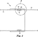
図3および図4は、本発明の好ましい実施形態を示す。この実施形態において、雄型管14は、凹部18を含み、雌型管12には対応する凹部がない。したがって、環状空間20は、雄型管14の凹部18から生じる。図1に示された実施形態と同様に、この実施形態は、好ましくは、雌型管の入口穴22と、また好ましくは雌型管の、出口穴24とを含む。
3 and 4 show a preferred embodiment of the present invention. In this embodiment, the
管の雄型端部および雌型端部が、重なりのために形成される場合、雌型管12が雄型管14の上を摺動できるように、雌型管12の内径が雄型管14の外径よりわずかに大きくなければならない。この隙間は、管構造の組立てを行うために十分に大きくすべきであるが、漏れを回避できるように最小化すべきでもある。良好な隙間は、典型的には、約0.15〜0.25mmであり、最も好ましくは、約0.005インチである。
When the male end and female end of the tube are formed for overlap, the inner diameter of the
雄型管14および/または雌型管12に溝を形成するとき、溝寸法の選択のための主な考慮事項は、接着剤の性能である。溝深さは、接着剤の流れを可能にするのに十分に深いことが単に要求される。応力/歪みが管の表面に集中することに留意することが重要である。したがって、溝の深さは、管が加えられた応力および歪みに耐える能力に実質的に影響を及ぼさない。したがって、これは、溝の深さを選択する際に主要な考慮事項ではない。典型的には、凹部は、深さが約0.5〜1mmであり、幅が約5〜15mmである。さらに、溝の中心から管セクションの端部まで、好ましくは約12〜15mmである。溝深さの非常に重要な考慮事項は、溝深さとフィットアップ隙間との比である。フィットアップ隙間は、雄型管と雌型管との間の隙間と定義する。押出におけるスロット−ダイフロー理論に基く計算により、溝深さが、パイプ端部を越える接着剤のバイパス漏れを防止するのに十分でなければならないことが示唆される。溝深さとフィットアップ隙間との比は、ここで有用なパラメータであり得る。約8の比を与える約0.040インチ(約1.0mm)の溝深さが、漏れを防止するのに十分な深さと考えられる。
When forming grooves in the
驚いたことに、上記の管の隙間と溝の深さとの比の慎重な選択によって、接着剤を入口穴22を通して環状領域20に注入し、ほぼ等しく分け、環状領域20を通って両方向にほぼ同じ速度で流すことが可能であることがわかった。これは、十分な降伏強度および接合部の耐漏れ性を確実にするのを助ける、環状領域20全体の均一な充填を確実にするのを助けるという点で重要である。好ましい比は、使用される特定の接着剤に依存するが、典型的には約8の範囲内である。溝深さも、この点で重要であろう。
Surprisingly, by careful selection of the ratio of the tube gap to the groove depth described above, the adhesive is injected through the
本発明に使用される接着剤は、接合部間の確実な結合をもたらし、この結合は、硬化すると、ハイドロフォーミング応力に耐え、かつ、結合された接合部による漏れを実質的に防止することができる。ハイドロフォーミングの間、接合部、および必然的に接着剤が、最終形態に再成形される。ハイドロフォーミング後、接着剤結合は、依然として、かなりの応力に耐えることができる確実な結合をもたらす。これは、結合された部品が自動車の構造フレームの一部を形成する場合に特に重要である。付加的な加熱工程も、自動車の形成に必要なことがあり、結合は、また、それらの特性を維持しながら、耐えることができなければならない。また、これらが構造部材に使用されるべきであることによって、結合は、確実な構造支持体を形成するために、経時的に十分な耐疲労性および環境耐久性を示さなければならない。 The adhesive used in the present invention provides a secure bond between joints that, when cured, can withstand hydroforming stresses and substantially prevent leakage through the bonded joints. it can. During hydroforming, the joint, and necessarily the adhesive, is reshaped to the final form. After hydroforming, the adhesive bond still provides a secure bond that can withstand considerable stress. This is particularly important when the joined parts form part of the automobile structural frame. Additional heating steps may also be necessary for the formation of automobiles and the bond must also be able to withstand while maintaining their properties. Also, because they should be used for structural members, the bond must exhibit sufficient fatigue resistance and environmental durability over time to form a solid structural support.
典型的には、二液性エポキシ接着剤が、硬化に必要な固有の反応性のため、本発明で使用するのに勧められる。この硬化は、接着剤と接触した金属表面を加熱することによって、たとえば誘導加熱によって、接着剤中に伝えられた熱による。本発明は、エポキシ接着剤の使用が必要ではないが、エポキシ接着剤の全物理特性が、本発明での使用に十分に適している。この用途のために接着剤を選択するときに考慮すべき重要な物理的特徴は、温度に対する未硬化接着剤のレオロジーおよび流動特徴ならびに接着剤の剪断速度である。硬化した接着剤の剪断降伏強度は、ハイドロフォーミング圧力に等しいか又はハイドロフォーミング圧力より高くなければならないと考えられる。接着剤の反応性は、サイクル時間要件を満たし、かつ、接着剤を、許容できるサイクル時間内に必要な強度レベルに硬化させるために重要である。最後に、硬化後のバルク機械的特性および結合特性が、上首尾のハイドロフォーミング性(hydroformability)およびその後の性能に重要である。選択される接着剤が、金属管による少なくとも約25%の好ましい伸びと比較して、少なくとも約10%の伸びを示すことが好ましい。接着剤は、少なくとも、予期されたハイドロフォーミング圧力と同じ剪断降伏応力を示さなければならないと考えられる。したがって、予期された最小ハイドロフォーミング圧力が約5000psi(約34MPa)であれば、好ましい接着剤の剪断降伏応力は、少なくとも約5000psiである。 Typically, two-part epoxy adhesives are recommended for use in the present invention because of the inherent reactivity required for curing. This curing is due to heat transferred into the adhesive by heating the metal surface in contact with the adhesive, for example by induction heating. Although the present invention does not require the use of an epoxy adhesive, the entire physical properties of the epoxy adhesive are well suited for use in the present invention. Important physical characteristics to consider when selecting an adhesive for this application are the rheological and flow characteristics of the uncured adhesive versus temperature and the shear rate of the adhesive. It is believed that the shear yield strength of the cured adhesive must be equal to or higher than the hydroforming pressure. Adhesive reactivity is important to meet cycle time requirements and to cure the adhesive to the required strength level within an acceptable cycle time. Finally, the bulk mechanical and bonding properties after curing are important for successful hydroformability and subsequent performance. It is preferred that the adhesive selected exhibits an elongation of at least about 10% compared to a preferred elongation of at least about 25% by the metal tube. It is believed that the adhesive must exhibit at least the same shear yield stress as the expected hydroforming pressure. Thus, if the expected minimum hydroforming pressure is about 5000 psi (about 34 MPa), the shear yield stress of the preferred adhesive is at least about 5000 psi.
本発明で使用するのに好ましい接着剤は、1998年10月13日付の米国特許出願第09/170597号明細書および国際公開第0022024 A2号パンフレットの主題である、ミネソタ・マイニング・アンド・マニュファクチャリング・カンパニー(Minnesota Mining and Manufacturing Company)によって開発された高強度エポキシ接着剤である。この接着剤は、本発明に用いるのに優れた物理特性を有する。この接着剤は、硬化後、およびその後、楕円形または円形断面から略矩形断面にハイドロフォーミングされたときでも、クラッキングに耐えることがわかっている。この耐クラッキング性は、新たな矩形断面のコーナの応力ポイントでも明らかである。 A preferred adhesive for use in the present invention is the Minnesota Mining and Manufacture, the subject of US patent application Ser. No. 09/170597 and WO0022024 A2, filed Oct. 13, 1998. A high strength epoxy adhesive developed by the Minnesota Mining and Manufacturing Company. This adhesive has excellent physical properties for use in the present invention. This adhesive has been found to resist cracking after curing and even when subsequently hydroformed from an elliptical or circular cross-section to a generally rectangular cross-section. This cracking resistance is also evident at the stress points of the new rectangular cross-section corners.
この接着剤を使用する場合、深さが約0.040インチ、幅が約3/8インチの環状領域が特に好ましいことがわかっている。約7.3の、溝深さ(この場合、約0.040インチ)と隙間(この場合、約0.0055インチ(約0.14mm))との比が、この接着剤で加工する場合に特に有利であることがわかっている。これらの寸法は、受入れられる特性を有する結合をもたらし、さらに、前述の、環状空間20を通る両方向でほぼ同じ接着剤の流れをもたらす。また、フィットアップ隙間と溝深さとの比は、漏れを低減または防止するのに重要である。接着剤は、たとえば静止混合システムによって、混合し、挿入することができ、また、接着剤の導入は、好ましくは、環状空間20が満たされるまで続かなければならない。この接着剤では、約0.20インチ(約5.1mm)の、より浅い溝深さが、パイプ端部を越える過度の漏れをもたらすことがわかり、したがって、比較的望ましくなかった。
When using this adhesive, an annular region having a depth of about 0.040 inch and a width of about 3/8 inch has been found to be particularly preferred. A ratio of groove depth (in this case about 0.040 inches) to clearance (in this case about 0.0055 inches) is about 7.3 when processed with this adhesive. It has proven particularly advantageous. These dimensions provide a bond with acceptable properties, and also provide approximately the same adhesive flow in both directions through the
本発明に好ましい管としては、金属管、好ましくは、高延性の加工された金属管、最も好ましくは、アルミニウム、アルミニウム合金、鉄、または鋼の加工された金属管が挙げられるであろう。選択される特定の管は、用いるべき特定のハイドロフォーミング圧力に大きく依存する。具体的な好ましい金属管としては、降伏強度が約30〜50ksi(約207〜345MPa)(1ksiは1平方インチあたり1000ポンド)、約30%の全伸びの、1008〜1010シリーズ鋼管を挙げることができる。さらに、高降伏強度(50+ksi)鋼管も、いくつかのハイドロフォーミング圧力に適切であろう。アルミニウムおよびアルミニウム合金も、適切なハイドロフォーミング材料であることができ、好ましいアルミニウム材料管としては、5000シリーズ、6061 T6シリーズ、および6061 T4シリーズアルミニウム管を挙げることができる。上記材料は好ましいと考えられるが、本発明は、必ずしも、そのように限定されることが意図されない。他の金属管も、本発明と関連して使用してもよい。 Preferred tubes for the present invention will include metal tubes, preferably high ductility processed metal tubes, most preferably processed metal tubes of aluminum, aluminum alloys, iron or steel. The particular tube chosen is highly dependent on the particular hydroforming pressure to be used. Specific preferred metal tubes include 1008-1010 series steel tubes with a yield strength of about 30-50 ksi (about 207-345 MPa) (1 ksi is 1000 pounds per square inch) and a total elongation of about 30%. it can. In addition, high yield strength (50 + ksi) steel pipes may also be suitable for some hydroforming pressures. Aluminum and aluminum alloys can also be suitable hydroforming materials, and preferred aluminum material tubes include 5000 series, 6061 T6 series, and 6061 T4 series aluminum tubes. While the above materials are considered preferred, the present invention is not necessarily intended to be so limited. Other metal tubes may also be used in connection with the present invention.
図3および図4に示された本発明の実施形態(すなわち、雄型管部分に溝があり、雌型管部分に溝がない実施形態)は、製造コストを最小にしながら、十分な構造強度をもたらすという点で、特に好ましい。 The embodiment of the present invention shown in FIGS. 3 and 4 (ie, the embodiment having a groove in the male tube portion and no groove in the female tube portion) provides sufficient structural strength while minimizing manufacturing costs. Is particularly preferred in that
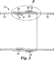
図5および図6は、本発明のさらなる実施形態を示し、雄型14管および雌型12管の各々は、凹部(それぞれ、18、16)を含むが、これらの凹部は、互いに対してずれるように配置されている。したがって、各凹部(18、16)は、環状領域20、21を形成する。この場合、環状領域20及び21の各々は、各々を充填できるように、個別の接着剤入口穴22および出口穴24を有する。本発明に関して、雄型管および雌型管が各々、1以上の環状領域を形成するために、1以上の凹部を含むことができることが理解されるべきである。これらの凹部は、対向する管の凹部と整列させることができるか、代わりに、どの対向する凹部とも整列させないことができ、したがって、付加的な環状領域を生じさせることができる。代わりに、管のいずれか一方が、他方の管が少なくとも1つの凹部を含む場合、凹部がなくてもよい(図3および図4に示されているように)。
5 and 6 show a further embodiment of the present invention, where each of the male 14 tube and the female 12 tube includes recesses (18, 16 respectively), which are offset with respect to each other. Are arranged as follows. Thus, each recess (18, 16) forms an
図7は、自動車フレームの構造に使用されるバードケージアセンブリ40を示す。多数の構造部材42が、接合部44でともに接合されて、バードケージ40を形成する。各接合部44は、好ましくは、上記のように接着剤によって接合される。バードケージアセンブリを使用して、自動車のフレームの一部または全体を形成することができる。
FIG. 7 shows a
この図からわかるように、さまざまな構造構成が、ハイドロフォーミングされた部品に可能である。本発明の1つの特徴は、180度(直線)の構成以外の管構成が可能であり、またこの図に示されているように、それらが所望の最終構造に必要であり得ることである。この180度でない角度構成を形成するために、雌型管部分は、接合部の外側に残りの部分を含むことができ、雄型管部分は、接合部の外側に残りの部分を含むことができる。雄型管部分の残りの部分は、前記雌型管部分の残りの部分に対して180度より大きいか小さい角度で配置することができ、したがって、非直線セグメントを形成することができる。これからわかるように、雌型管部分および雄型管部分の残りは、L字形、T字形、S字形、または十字形などのさまざまな形状を形成することができる。 As can be seen from this figure, various structural configurations are possible for hydroformed parts. One feature of the present invention is that tube configurations other than a 180 degree (straight) configuration are possible and, as shown in this figure, they may be necessary for the desired final structure. To form this non-180 degree angular configuration, the female tube portion can include the remaining portion outside the joint, and the male tube portion can include the remaining portion outside the joint. it can. The remaining portion of the male tube portion can be disposed at an angle greater than or less than 180 degrees relative to the remaining portion of the female tube portion, thus forming a non-linear segment. As can be seen, the remainder of the female tube portion and the male tube portion can form a variety of shapes, such as L-shaped, T-shaped, S-shaped, or cross-shaped.
図8は、バードケージアセンブリ40の接合部44(およびしたがって図示されていない環状領域)に接着剤を注入する機械46を概略的に示す。接着剤は、ロボットアーム48によって注入される。この機械を使用すると、接着剤を注入するプロセスを自動化することができ、したがって、ハイドロフォーミング可能な(hydroformable)アセンブリを形成する時間および費用を大きく低減することができる。このことは、車両フレームの製造コスト全体を大きく低減することができる。
FIG. 8 schematically illustrates a
本発明の方法によれば、所望の重なりに適切な直径を有する雄型端部および雌型端部を含むように、フレーム部材を形成することができる。重なりの領域において、好ましくは端部形成工具によって、これらの部材のいずれかまたは両方に、1以上の溝を形成する。次に、好ましくは、脱脂溶液または脱脂溶媒ワイプによって管を処理し、次に、最終的な所望の重なり位置にともに配置する。フレームエレメントの連結前または後に、接着剤入口穴および空気出口穴を管に形成することができる。 According to the method of the present invention, the frame member can be formed to include a male end and a female end having the appropriate diameter for the desired overlap. In the overlap region, one or more grooves are formed in either or both of these members, preferably by an end forming tool. The tubes are then preferably treated with a degreasing solution or degreasing solvent wipe and then placed together in the final desired overlap location. Adhesive inlet holes and air outlet holes can be formed in the tube before or after the frame elements are connected.
いったんフレームエレメントを適切に位置合せすると、好ましくは接着剤入口穴を通る注入によって、接着剤を環状領域に導入する。接着剤の注入は、接着剤が環状領域全体をほぼ満たすまで続ける。これは、注入速度および注入時間を自動的に測定し、これを、充填すべき環状領域の体積と比較することによって、および/またはいつ接着剤が環状領域を満たしたかを見るために出口穴を外観検査することによって、測定することができる。 Once the frame element is properly aligned, the adhesive is introduced into the annular region, preferably by injection through the adhesive inlet hole. Adhesive injection continues until the adhesive substantially fills the entire annular region. This automatically measures the injection rate and injection time and compares this with the volume of the annular region to be filled and / or to see when the adhesive has filled the annular region. It can be measured by visual inspection.
接着剤の注入後、接着剤を硬化させることができる。典型的には、接合された構造を、周囲条件においてある期間、たとえば約24時間、保持し、次に、硬化させる。硬化は、典型的には、加熱、たとえば、強制空気オーブン内で、または誘導加熱によって、行われる。硬化した接着剤は、ハイドロフォーミングプロセスの高圧力および結果として生じる応力に耐えることができなければならない。 After the injection of the adhesive, the adhesive can be cured. Typically, the bonded structure is held at ambient conditions for a period of time, for example about 24 hours, and then cured. Curing is typically done by heating, eg, in a forced air oven or by induction heating. The cured adhesive must be able to withstand the high pressures and resulting stresses of the hydroforming process.
接着剤の硬化後、構造をハイドロフォーミングダイ内に配置し、7,000psi(48MPa)を超え得る必要なハイドロフォーミング圧力に加圧することができる。このハイドロフォーミング工程では、管状パイプセクションを、ダイの形状に対応し、典型的には矩形断面を有する、最終的な所望の形状に形成する。 After the adhesive is cured, the structure can be placed in a hydroforming die and pressurized to the required hydroforming pressure, which can exceed 7,000 psi (48 MPa). In this hydroforming process, the tubular pipe section is formed into a final desired shape that corresponds to the shape of the die and typically has a rectangular cross section.
ハイドロフォーミングによって車両フレームを形成する既知のシステムは、後で溶接してアセンブリ全体にする個別の部品をともにハイドロフォーミングすることに依存する。したがって、ハイドロフォーミングは、溶接後に行われない。本発明を用いることによって、車両フレームのかなりの部分を同時にハイドロフォーミングすることができ、必要な後形成溶接部はずっと少なくなる。好ましくは、自動車用のフレーム全体またはバードケージは、1つのハイドロフォーミング作業で同時に成形される。 Known systems for forming vehicle frames by hydroforming rely on hydroforming together the individual parts that are later welded together to form the entire assembly. Therefore, hydroforming is not performed after welding. By using the present invention, a significant portion of the vehicle frame can be hydroformed simultaneously and much less post-forming welds are required. Preferably, the entire automobile frame or birdcage is molded simultaneously in one hydroforming operation.
本発明によれば、車両フレームのかなりの部分(たとえば、ラジエータ支持構造)を形成するか、完全なフレーム(バードケージ)を形成するために、個別のコンポーネントを、上記のようにともに嵌合するように雄型端部および雌型端部を備えて、設計することができる。次に、さまざまな、結果として生じる環状空間に、接着剤を注入することができ、アセンブリ全体を加熱して、接着剤を硬化させることができる。したがって、このプロセスによって、必要な溶接部の数を大きく低減して、車両の製造コストを低下させることができる。最後に、硬化後、構造全体をハイドロフォーミングダイ内に配置して、1つのハイドロフォーミング工程で、最終的な好ましいジオメトリにハイドロフォーミングすることができる。この場合、各接合部は、必要な構造一体性をもたらすだけでなく、ハイドロフォーミング圧力に耐えなければならない。接合部の欠陥による漏れは、必要な加圧を妨げることがあり、また、最終構造の完全な成形を妨げることがある。 In accordance with the present invention, the individual components are mated together as described above to form a significant portion of the vehicle frame (eg, radiator support structure) or to form a complete frame (birdcage). Thus, it can be designed with a male end and a female end. The adhesive can then be injected into the various resulting annular spaces and the entire assembly can be heated to cure the adhesive. Therefore, this process can greatly reduce the number of necessary welds and reduce the manufacturing cost of the vehicle. Finally, after curing, the entire structure can be placed in a hydroforming die and hydroformed into the final preferred geometry in one hydroforming step. In this case, each joint must not only provide the necessary structural integrity but also withstand the hydroforming pressure. Leakage due to joint defects can prevent the required pressurization and can prevent complete molding of the final structure.
実施例1
壁厚さが1mmの外径63.5mm(2.5インチ)雌型パイプを、65.5mmに拡大させ、拡大長さをパイプの端部から30mmにした。パイプの内側に深さ1.0mm、幅10mmの溝を形成し、溝の中心線を開端から約12mm離した。対応する雄型パイプは、拡大されていない挿入端部に形成された同じ寸法の溝を有した。雄型パイプおよび雌型パイプの両方に入口穴および出口穴をあけた。溝が整合するように、雄型パイプを雌型パイプに挿入した。接着剤を加える前に、160°F(71℃)のオアカイト(Oakite)164苛性溶液中に10分間浸漬することによって、パイプを脱脂した。ミネソタ・マイニング・アンド・マニュファクチャリング・コーポレイション(Minnesota Mining and Manufacturing Corporation)から入手可能な二液性構造用接着剤、SA8051の10:1混合物を、8〜24スタティックミキサーノズルによって混合し、注入穴を通して両方の空洞に注入した。結果として生じるアセンブリを、24時間、周囲条件で保持し、次に、171℃で、強制空気オーブン内に30分間配置した。次に、硬化したアセンブリを、5000psi(34MPa)で、基本的に楕円形の形状から本質的に矩形の形状に、首尾よくハイドロフォーミングした。ハイドロフォーミング後、接合部は漏れがなかった。
Example 1
An outer diameter 63.5 mm (2.5 inch) female pipe with a wall thickness of 1 mm was expanded to 65.5 mm and the expanded length was 30 mm from the end of the pipe. A groove having a depth of 1.0 mm and a width of 10 mm was formed inside the pipe, and the center line of the groove was separated from the open end by about 12 mm. The corresponding male pipe had a groove of the same dimensions formed in the unexpanded insertion end. Both male and female pipes were drilled with inlet and outlet holes. The male pipe was inserted into the female pipe so that the grooves were aligned. Prior to adding the adhesive, the pipes were defatted by dipping in a 160 ° F. (71 ° C.) Oakite 164 caustic solution for 10 minutes. A 10: 1 mixture of two-component structural adhesive, SA8051, available from Minnesota Mining and Manufacturing Corporation, is mixed by 8-24 static mixer nozzles and filled with holes. Through both cavities. The resulting assembly was held at ambient conditions for 24 hours and then placed in a forced air oven at 171 ° C. for 30 minutes. The cured assembly was then successfully hydroformed at 5000 psi (34 MPa) from an essentially elliptical shape to an essentially rectangular shape. There was no leakage at the joint after hydroforming.
実施例2
雌型パイプ(実施例1とほぼ同じ寸法を有する)の一端を、雄型パイプを受けるために拡大した。雌型パイプに入口穴および出口穴を設けた。0.50mm×10.0mmの溝を雄型パイプに設け、雄型パイプを雌型パイプに挿入した。雄型パイプの他の寸法は、実施例1で説明されたのとほぼ同じであった。洗浄、接着剤注入、硬化、およびハイドロフォーミングを、実施例1で説明されたように行った。ハイドロフォーミング後、接合部は、耐漏れ性であった。
Example 2
One end of the female pipe (having approximately the same dimensions as Example 1) was enlarged to receive the male pipe. An inlet hole and an outlet hole were provided in the female pipe. A 0.50 mm × 10.0 mm groove was provided in the male pipe, and the male pipe was inserted into the female pipe. The other dimensions of the male pipe were almost the same as described in Example 1. Cleaning, adhesive injection, curing, and hydroforming were performed as described in Example 1. After hydroforming, the joint was leakproof.
実施例3
上記実施例1と同様に、雄型パイプおよび雌型パイプの両方に溝を形成した。組立てると、溝は互いに10.0mmずれた。各溝に対応する入口穴および出口穴を雌型パイプに設けた。洗浄、接着剤注入、硬化、およびハイドロフォーミングを、実施例1で説明されたように行った。ハイドロフォーミングすると、接合部は、耐漏れ性であった。
Example 3
In the same manner as in Example 1, grooves were formed in both the male pipe and the female pipe. When assembled, the grooves were shifted 10.0 mm from each other. An inlet hole and an outlet hole corresponding to each groove were provided in the female pipe. Cleaning, adhesive injection, curing, and hydroforming were performed as described in Example 1. When hydroformed, the joint was leakproof.
実施例4
本発明の実施形態と関連して、ロボットによって組立てられた20までの接合部からなるフレームに、接着剤を注入し、次に、クラムシェル加熱コイルによる誘導加熱サイクルにかけることができる。この実施形態において、30秒の加熱サイクルが、接着剤を完全に硬化させるのに十分であり得る。次に、ユニット全体を、所望の最終構成に首尾よくハイドロフォーミングすることができる。本発明を用いることによって、フレーム構造を形成するのに必要な人力および関連する費用を著しく低減できることが、この実施例からわかる。
Example 4
In connection with embodiments of the present invention, adhesive can be injected into a frame of up to 20 joints assembled by a robot and then subjected to an induction heating cycle with clamshell heating coils. In this embodiment, a 30 second heating cycle may be sufficient to fully cure the adhesive. The entire unit can then be successfully hydroformed to the desired final configuration. It can be seen from this example that by using the present invention, the manpower and associated costs required to form the frame structure can be significantly reduced.
上記開示および本発明の一般原理および先の詳細な説明から、当業者は、本発明に可能なさまざまな修正を容易に理解するであろう。したがって、本発明の範囲は、特許請求の範囲およびその均等物によってのみ限定されるべきである。 From the above disclosure and general principles of the invention and the foregoing detailed description, those skilled in the art will readily appreciate the various modifications possible to the invention. Therefore, the scope of the present invention should be limited only by the claims and their equivalents.
Claims (6)
前記雄型管部分および前記雌型管部分の少なくとも一方に形成され、前記雄型管部分と前記雌型管部分との間に環状領域を形成する溝と、
前記雄型管部分と前記雌型管部分との間の前記環状領域に配置されて接合部を形成する、硬化した接着剤と、
前記接着剤を前記環状領域内に導入するための、前記雌型管部分に形成されかつ前記環状領域に連通する入口穴と、を含むハイドロフォーミング可能な物品であって、
前記物品が最終形状に形成されたときに、前記接合部は、ハイドロフォーミングプロセスにおいて実質的に耐漏れ性であるとともに、構造部材として使用されるべき十分な強度、耐疲労性および耐久性を備える、ハイドロフォーミング可能な物品。 A female tube portion and a male tube portion, wherein a portion of the female tube portion is disposed around a portion of the male tube portion; and
A groove formed in at least one of the male tube portion and the female tube portion, and forming an annular region between the male tube portion and the female tube portion;
A cured adhesive disposed in the annular region between the male tube portion and the female tube portion to form a joint; and
A hydroforming article that includes an inlet hole formed in the female tube portion and communicating with the annular region for introducing the adhesive into the annular region;
When the article is formed into a final shape, the joint is substantially leakproof in the hydroforming process and has sufficient strength, fatigue resistance and durability to be used as a structural member. Articles that can be hydroformed .
Applications Claiming Priority (3)
| Application Number | Priority Date | Filing Date | Title |
|---|---|---|---|
| US09/997,947 | 2001-11-30 | ||
| US09/997,947 US6742258B2 (en) | 2001-11-30 | 2001-11-30 | Method of hydroforming articles and the articles formed thereby |
| PCT/US2002/036922 WO2003047785A1 (en) | 2001-11-30 | 2002-11-18 | Method of hydroforming articles and the articles formed thereby |
Publications (3)
| Publication Number | Publication Date |
|---|---|
| JP2005511308A JP2005511308A (en) | 2005-04-28 |
| JP2005511308A5 JP2005511308A5 (en) | 2006-01-05 |
| JP4927315B2 true JP4927315B2 (en) | 2012-05-09 |
Family
ID=25544589
Family Applications (1)
| Application Number | Title | Priority Date | Filing Date |
|---|---|---|---|
| JP2003549025A Expired - Fee Related JP4927315B2 (en) | 2001-11-30 | 2002-11-18 | Method for hydroforming articles and articles formed thereby |
Country Status (8)
| Country | Link |
|---|---|
| US (2) | US6742258B2 (en) |
| EP (1) | EP1448328B1 (en) |
| JP (1) | JP4927315B2 (en) |
| CN (1) | CN1284641C (en) |
| AT (1) | ATE393675T1 (en) |
| AU (1) | AU2002352763A1 (en) |
| DE (1) | DE60226336T2 (en) |
| WO (1) | WO2003047785A1 (en) |
Families Citing this family (74)
| Publication number | Priority date | Publication date | Assignee | Title |
|---|---|---|---|---|
| US6620501B1 (en) * | 2000-08-07 | 2003-09-16 | L&L Products, Inc. | Paintable seal system |
| US6682818B2 (en) * | 2001-08-24 | 2004-01-27 | L&L Products, Inc. | Paintable material |
| EP1432606B1 (en) * | 2001-10-02 | 2005-12-28 | Magna International Inc | Truck cab space frame |
| US6742258B2 (en) * | 2001-11-30 | 2004-06-01 | 3M Innovative Properties Company | Method of hydroforming articles and the articles formed thereby |
| US7043815B2 (en) * | 2002-01-25 | 2006-05-16 | L & L Products, Inc. | Method for applying flowable materials |
| US7004536B2 (en) * | 2002-07-29 | 2006-02-28 | L&L Products, Inc. | Attachment system and method of forming same |
| US6922882B2 (en) * | 2003-05-19 | 2005-08-02 | General Motors Corporation | Method of joining tubular members |
| AT412550B (en) * | 2003-06-24 | 2005-04-25 | Voestalpine Stahl Gmbh | CARRIER FOR A VEHICLE BODY |
| JP2005119434A (en) * | 2003-10-16 | 2005-05-12 | Honda Motor Co Ltd | Automobile guard pipe |
| CA2540844C (en) * | 2003-10-20 | 2015-02-17 | Magna International Inc. | Hybrid component |
| US8496258B2 (en) * | 2003-10-20 | 2013-07-30 | Magna International Inc. | Hybrid component |
| DE10356533B4 (en) * | 2003-12-04 | 2005-10-06 | Daimlerchrysler Ag | Method for joining joining parts to hollow profiles |
| GB0402221D0 (en) | 2004-02-02 | 2004-03-03 | L & L Products Inc | Improvements in or relating to composite materials |
| US7341285B2 (en) * | 2004-03-24 | 2008-03-11 | Ips Corporation Weld-On Division | Chemical fusion of non-metallic pipe joints |
| US7180027B2 (en) * | 2004-03-31 | 2007-02-20 | L & L Products, Inc. | Method of applying activatable material to a member |
| US20050221046A1 (en) * | 2004-04-01 | 2005-10-06 | L&L Products, Inc. | Sealant material |
| CA2503477C (en) * | 2004-04-02 | 2012-01-31 | Magna International Inc. | Frame for a motor vehicle |
| US7838589B2 (en) * | 2004-07-21 | 2010-11-23 | Zephyros, Inc. | Sealant material |
| US7521093B2 (en) * | 2004-07-21 | 2009-04-21 | Zephyros, Inc. | Method of sealing an interface |
| US7392929B1 (en) | 2004-07-26 | 2008-07-01 | Zephyros, Inc. | Weldable synthetic material |
| US7278212B2 (en) * | 2004-10-06 | 2007-10-09 | American Axle & Manufacturing, Inc. | Universal joint with adhesive bearing cup retention method |
| US20060108783A1 (en) * | 2004-11-24 | 2006-05-25 | Chi-Mou Ni | Structural assembly for vehicles and method of making same |
| TWM271973U (en) * | 2004-12-24 | 2005-08-01 | Ching-Wen Chen | Improved connection structure of a metal connector |
| US7377598B2 (en) | 2005-01-10 | 2008-05-27 | American Axle & Manufacturing, Inc. | Axle housing assembly and method |
| US20070087848A1 (en) * | 2005-04-29 | 2007-04-19 | L&L Products, Inc. | Dampener |
| US7926179B2 (en) | 2005-08-04 | 2011-04-19 | Zephyros, Inc. | Reinforcements, baffles and seals with malleable carriers |
| JP2007107658A (en) * | 2005-10-14 | 2007-04-26 | Pentax Corp | Fixing structure of insertion member |
| US20090272453A1 (en) * | 2006-04-04 | 2009-11-05 | Karl Schlecht | Transport Pipe for Thick Materials |
| US7472486B2 (en) * | 2006-05-19 | 2009-01-06 | The Stanley Works | Level with vial and manufacturing method therefor |
| US20080030030A1 (en) * | 2006-08-02 | 2008-02-07 | Taiwan Fu Hsing Industrial Co., Ltd. | Door lever and door lever assembly |
| US8236128B2 (en) * | 2006-10-26 | 2012-08-07 | Zephyros, Inc. | Adhesive materials, adhesive parts formed therewith and their uses |
| US7941907B2 (en) * | 2006-10-31 | 2011-05-17 | GM Global Technology Operations LLC | Method for manufacture of shaped tubular part |
| US20080226866A1 (en) * | 2007-03-15 | 2008-09-18 | Zephyros, Inc. | Sealant material |
| US8020272B2 (en) | 2007-04-20 | 2011-09-20 | GM Global Technology Operations LLC | Method for joining tubes |
| JP5291336B2 (en) * | 2007-12-27 | 2013-09-18 | 日本管洗工業株式会社 | Method and structure for joining metal members |
| DE102008038276B4 (en) * | 2008-08-18 | 2018-02-15 | Benteler Automobiltechnik Gmbh | Method for connecting chassis parts and chassis assembly |
| US8397463B2 (en) * | 2009-02-03 | 2013-03-19 | Allred & Associates Inc. | 3-dimensional universal tube connector system |
| US8528291B2 (en) * | 2009-02-03 | 2013-09-10 | Allred & Associates Inc. | 3-dimensional universal tube connector system |
| US8870488B2 (en) * | 2009-06-19 | 2014-10-28 | Duracase Proprietary Llc | Joint assembly with reinforcing member and foam |
| DE102010004155A1 (en) * | 2010-01-04 | 2011-07-07 | V & M Deutschland GmbH, 40472 | Connecting arrangement of hollow steel under axial pressure profiles |
| JP5710223B2 (en) * | 2010-11-19 | 2015-04-30 | シロキ工業株式会社 | Method for manufacturing door frame made of light metal material |
| US9382933B2 (en) * | 2011-04-04 | 2016-07-05 | Textron Innovations Inc. | Self pumping and priming adhesive joint system |
| DE102011104483A1 (en) * | 2011-06-17 | 2012-12-20 | MAN Truck & Bus Aktiengesellschaft | Frame longitudinal support structure for chassis frames of commercial vehicles, in particular of trucks and / or buses |
| US9039061B2 (en) * | 2011-08-30 | 2015-05-26 | Ford Global Technologies, Llc | Vehicle frame assemblies with threaded connections |
| FR2980251B1 (en) * | 2011-09-16 | 2014-08-22 | Daher Aerospace | METHOD FOR ASSEMBLING A STRUCTURE CALLED CAISSON AND STRUCTURE OBTAINED BY SUCH A METHOD |
| GB201207481D0 (en) | 2012-04-26 | 2012-06-13 | Zephyros Inc | Applying flowable materials to synthetic substrates |
| US9328266B2 (en) | 2012-07-09 | 2016-05-03 | Gm Global Technology Operations, Llc | Method for mitigating cure shrinkage in high temperature-processed thermosetting adhesives and SMC |
| FR3006393B1 (en) * | 2013-05-30 | 2016-04-29 | Peugeot Citroen Automobiles Sa | METHOD FOR ASSEMBLING TUBES BY ADDING GLASS AND DASHBOARD TRAVERSE OBTAINED BY SUCH A METHOD |
| CN109080735B (en) | 2014-05-16 | 2022-05-03 | 迪根特技术公司 | Modular forming node for vehicle chassis and using method thereof |
| US10138925B2 (en) * | 2014-05-26 | 2018-11-27 | Fujikura Rubber Ltd. | FRP drive shaft |
| JP6131917B2 (en) * | 2014-06-30 | 2017-05-24 | トヨタ自動車株式会社 | Bonding structure for vehicle panels |
| US10960929B2 (en) | 2014-07-02 | 2021-03-30 | Divergent Technologies, Inc. | Systems and methods for vehicle subassembly and fabrication |
| MX2017000061A (en) | 2014-07-02 | 2017-05-23 | Divergent Tech Inc | Systems and methods for fabricating joint members. |
| US9719490B2 (en) * | 2014-10-31 | 2017-08-01 | General Electric Company | Wind turbine blade with bond paste inspection window and associated method |
| US11198236B2 (en) | 2014-11-14 | 2021-12-14 | Zephyros, Inc. | Multi-shot injection molded method and product |
| DE102014118489A1 (en) * | 2014-12-12 | 2016-06-16 | Karlsruher Institut für Technologie | Connection between two joining partners and method of making the connection |
| AU2016270457A1 (en) * | 2015-06-04 | 2018-01-18 | Divergent Technologies, Inc. | Systems and methods for adhesive injection for node assembly |
| US10695962B2 (en) | 2016-03-18 | 2020-06-30 | Zephyros, Inc. | Members for directing expandable material for baffling, sealing, reinforcing |
| CN107962847B (en) | 2016-10-19 | 2020-06-26 | 泽费罗斯股份有限公司 | Acoustic absorber composite baffle assembly |
| EP3589849A1 (en) * | 2017-03-01 | 2020-01-08 | Ford Global Technologies, LLC | Method of assembly for 3d printed vehicle architecture, joints |
| CN107023725B (en) * | 2017-03-24 | 2019-04-23 | 湖北三江航天红阳机电有限公司 | A kind of hose adhering method |
| WO2018234082A1 (en) * | 2017-06-22 | 2018-12-27 | Sika Technology Ag | Connection of elements in motor vehicles |
| US11535307B2 (en) | 2017-06-22 | 2022-12-27 | Sika Technology Ag | Reinforcing element, system of a reinforced structural element and method for reinforcing a structural element |
| KR102556259B1 (en) * | 2017-06-22 | 2023-07-14 | 시카 테크놀러지 아게 | Connection of car body elements |
| DE202017105474U1 (en) | 2017-09-08 | 2018-12-14 | Edag Engineering Gmbh | Material-optimized connection node |
| US11131620B1 (en) * | 2017-12-29 | 2021-09-28 | Swift IP, LLC | Methods of bonding articles using moisture-curing adhesive composition |
| JP7067305B2 (en) * | 2018-06-20 | 2022-05-16 | トヨタ自動車株式会社 | Member joining method and member joining device |
| CA3128005A1 (en) * | 2019-02-07 | 2020-08-13 | Ips Corporation | Gasketed pipe joint formed in place and method of making same |
| EP4032755A1 (en) * | 2021-01-26 | 2022-07-27 | Volvo Construction Equipment AB | Support structure for a vehicle and method for assembling parts of a support structure for a vehicle |
| EP4043737A1 (en) * | 2021-02-10 | 2022-08-17 | B/E Aerospace, Inc. | Bonding concentric elements |
| US11613224B2 (en) * | 2021-02-17 | 2023-03-28 | Ford Global Technologies, Llc | Open frame vehicle multifunctional sport tube |
| CN113202849A (en) * | 2021-05-08 | 2021-08-03 | 哈尔滨工业大学(威海) | Carbon fiber pipe and metal joint glue connection process and metal joint |
| DE102021005061A1 (en) | 2021-10-08 | 2021-12-02 | Daimler Ag | Process for the production of a profile by means of hydroforming |
| GB2614924A (en) * | 2022-01-25 | 2023-07-26 | Ocado Innovation Ltd | Glue joint |
Family Cites Families (33)
| Publication number | Priority date | Publication date | Assignee | Title |
|---|---|---|---|---|
| US3210102A (en) * | 1964-07-22 | 1965-10-05 | Joslin Alvin Earl | Pipe coupling having a deformed inner lock |
| FR1450810A (en) * | 1965-07-15 | 1966-06-24 | Vallourec | New method of fixing by gluing two cylindrical metal parts and resulting product |
| BE794882A (en) * | 1972-02-15 | 1973-05-29 | Stewing Albert | CHANNEL SHEATH FOR CABLES AND METHOD FOR ITS REALIZATION |
| US3847695A (en) * | 1973-06-28 | 1974-11-12 | J Gross | Rimless recapping apparatus utilizing balanced air pressures |
| US5209541A (en) * | 1992-04-13 | 1993-05-11 | Ford Motor Company | Space frame joint construction |
| EP0568215A1 (en) * | 1992-04-29 | 1993-11-03 | Ford Motor Company Limited | Space frame construction |
| US5794398A (en) * | 1992-08-25 | 1998-08-18 | Kaehler; Klaus | Framework with hollow members process for producing the same and its use |
| SE501667C2 (en) | 1993-07-05 | 1995-04-10 | Borealis Ind Ab | Bonding of joints and connectors |
| US5613794A (en) * | 1994-08-16 | 1997-03-25 | Hong Kong (Link) Bicycles Ltd. | Bi-material tubing and method of making same |
| DE19519353A1 (en) * | 1995-05-26 | 1996-11-28 | Porsche Ag | Carrier of a vehicle body structure and method for its production |
| ZA973413B (en) * | 1996-04-30 | 1998-10-21 | Autokinetics Inc | Modular vehicle frame |
| DE19632275C2 (en) | 1996-08-09 | 2001-02-22 | Drei Bond Gmbh Chemische Verbi | Sealing and adhesive process for component connections |
| US5720092A (en) * | 1996-08-21 | 1998-02-24 | General Motors Corporation | Method for hydroforming a vehicle space frame |
| DE19653509B4 (en) * | 1996-12-20 | 2006-06-08 | Volkswagen Ag | Frame structure of a vehicle body of node elements and connected, pre-profiled support elements |
| NL1005423C2 (en) | 1997-03-03 | 1998-09-18 | Polva Pipelife Bv | Adhesive sleeve connection, and adhesive sleeve therefor. |
| DE19716865C1 (en) * | 1997-04-22 | 1998-05-28 | Porsche Ag | Tubular frame shape by internal hydraulic pressure for vehicle chassis |
| GB2328393A (en) * | 1997-08-21 | 1999-02-24 | Rover Group | Securing components together and a structural member so formed |
| US6116680A (en) * | 1997-10-01 | 2000-09-12 | Aluminum Company Of America | Structural component for vehicle body-in-white |
| US6092865A (en) * | 1997-10-16 | 2000-07-25 | Cosma International Inc. | Hydroformed space frame and method of manufacturing the same |
| US6346684B1 (en) * | 1997-10-16 | 2002-02-12 | Cosma International Inc. | Welding material assembly and method |
| US6623067B2 (en) * | 1997-10-16 | 2003-09-23 | Magna International Inc. | Door seal interface structure for a motor vehicle space frame |
| US6308412B1 (en) * | 1997-12-31 | 2001-10-30 | Dana Corporation | Joint between cross member and side rail in a vehicle frame assembly |
| US6408515B1 (en) * | 1998-08-20 | 2002-06-25 | Dana Corporation | Method for manufacturing an engine cradle for a vehicle frame assembly |
| US6216509B1 (en) | 1998-08-25 | 2001-04-17 | R.J. Tower Corporation | Hydroformed tubular member and method of hydroforming tubular members |
| US6486256B1 (en) | 1998-10-13 | 2002-11-26 | 3M Innovative Properties Company | Composition of epoxy resin, chain extender and polymeric toughener with separate base catalyst |
| US6183013B1 (en) | 1999-07-26 | 2001-02-06 | General Motors Corporation | Hydroformed side rail for a vehicle frame and method of manufacture |
| US6668457B1 (en) * | 1999-12-10 | 2003-12-30 | L&L Products, Inc. | Heat-activated structural foam reinforced hydroform |
| US6654995B1 (en) * | 2000-10-16 | 2003-12-02 | General Motors Corporation | Method for joining tubular members |
| US6505389B2 (en) * | 2000-12-19 | 2003-01-14 | F&P Mfg., Inc. | Apparatus and method for forming a tube having an article attached thereto |
| US6898923B2 (en) * | 2001-06-11 | 2005-05-31 | Sagoma Plastics Corporation | Disc packaging |
| US6701763B2 (en) * | 2001-08-27 | 2004-03-09 | Meritor Heavy Vehicle Technology | Hydroformed axle with weldless brake flange and bearing shoulder |
| US6742258B2 (en) * | 2001-11-30 | 2004-06-01 | 3M Innovative Properties Company | Method of hydroforming articles and the articles formed thereby |
| US6922882B2 (en) * | 2003-05-19 | 2005-08-02 | General Motors Corporation | Method of joining tubular members |
-
2001
- 2001-11-30 US US09/997,947 patent/US6742258B2/en not_active Expired - Lifetime
-
2002
- 2002-11-18 JP JP2003549025A patent/JP4927315B2/en not_active Expired - Fee Related
- 2002-11-18 WO PCT/US2002/036922 patent/WO2003047785A1/en active Application Filing
- 2002-11-18 CN CN02823894.XA patent/CN1284641C/en not_active Expired - Fee Related
- 2002-11-18 AT AT02789716T patent/ATE393675T1/en not_active IP Right Cessation
- 2002-11-18 DE DE60226336T patent/DE60226336T2/en not_active Expired - Lifetime
- 2002-11-18 AU AU2002352763A patent/AU2002352763A1/en not_active Abandoned
- 2002-11-18 EP EP02789716A patent/EP1448328B1/en not_active Expired - Lifetime
-
2004
- 2004-04-16 US US10/826,893 patent/US7175204B2/en not_active Expired - Lifetime
Also Published As
| Publication number | Publication date |
|---|---|
| EP1448328A1 (en) | 2004-08-25 |
| DE60226336T2 (en) | 2009-05-20 |
| US20040195817A1 (en) | 2004-10-07 |
| DE60226336D1 (en) | 2008-06-12 |
| US20030102668A1 (en) | 2003-06-05 |
| ATE393675T1 (en) | 2008-05-15 |
| CN1284641C (en) | 2006-11-15 |
| AU2002352763A1 (en) | 2003-06-17 |
| EP1448328B1 (en) | 2008-04-30 |
| US7175204B2 (en) | 2007-02-13 |
| CN1596161A (en) | 2005-03-16 |
| WO2003047785A1 (en) | 2003-06-12 |
| US6742258B2 (en) | 2004-06-01 |
| JP2005511308A (en) | 2005-04-28 |
Similar Documents
| Publication | Publication Date | Title |
|---|---|---|
| JP4927315B2 (en) | Method for hydroforming articles and articles formed thereby | |
| JP7223102B2 (en) | Manufacturing method by fluid system and friction welding | |
| CN100364685C (en) | Production of clad pipes | |
| DE102008019354B4 (en) | Method for joining pipes | |
| JP2005511308A5 (en) | ||
| JP6868336B2 (en) | Double-walled titanium tube material and method for manufacturing the tube material | |
| KR20070036160A (en) | Improvements in tubular bodies and methods of forming same | |
| US20080028592A1 (en) | Method of coupling plastic components to metal tubing | |
| US20170113257A1 (en) | Method for producing a large multilayer pipe | |
| JP2001334316A (en) | Tubular product of special form and its manufacturing method | |
| EP1749639B1 (en) | Method for making plastic metal composite parts | |
| CN207796314U (en) | A kind of non-uniform thickness hydroforming flexible composite pipe | |
| KR102072794B1 (en) | Clad pipe producting apparatus using water pressure expansion and clad pipe producting method | |
| KR20100013901A (en) | Molding apparatus for hydro-forming and moldings | |
| CN108150737A (en) | A kind of non-uniform thickness hydroforming flexible composite pipe | |
| JP2006088165A (en) | Article formed by hydrostatic bulging and hydrostatic bulge forming method | |
| JPH029543B2 (en) | ||
| JPS5837128B2 (en) | It's a long time since I've been in the middle of a long time. | |
| JPH01320307A (en) | Butt joint tight fastening method |
Legal Events
| Date | Code | Title | Description |
|---|---|---|---|
| A521 | Request for written amendment filed |
Free format text: JAPANESE INTERMEDIATE CODE: A523 Effective date: 20051020 |
|
| A621 | Written request for application examination |
Free format text: JAPANESE INTERMEDIATE CODE: A621 Effective date: 20051020 |
|
| A131 | Notification of reasons for refusal |
Free format text: JAPANESE INTERMEDIATE CODE: A131 Effective date: 20080729 |
|
| A601 | Written request for extension of time |
Free format text: JAPANESE INTERMEDIATE CODE: A601 Effective date: 20081028 |
|
| A602 | Written permission of extension of time |
Free format text: JAPANESE INTERMEDIATE CODE: A602 Effective date: 20081105 |
|
| A521 | Request for written amendment filed |
Free format text: JAPANESE INTERMEDIATE CODE: A523 Effective date: 20090129 |
|
| A02 | Decision of refusal |
Free format text: JAPANESE INTERMEDIATE CODE: A02 Effective date: 20090811 |
|
| A521 | Request for written amendment filed |
Free format text: JAPANESE INTERMEDIATE CODE: A523 Effective date: 20091211 |
|
| A911 | Transfer to examiner for re-examination before appeal (zenchi) |
Free format text: JAPANESE INTERMEDIATE CODE: A911 Effective date: 20111006 |
|
| TRDD | Decision of grant or rejection written | ||
| A01 | Written decision to grant a patent or to grant a registration (utility model) |
Free format text: JAPANESE INTERMEDIATE CODE: A01 Effective date: 20120110 |
|
| A01 | Written decision to grant a patent or to grant a registration (utility model) |
Free format text: JAPANESE INTERMEDIATE CODE: A01 |
|
| A61 | First payment of annual fees (during grant procedure) |
Free format text: JAPANESE INTERMEDIATE CODE: A61 Effective date: 20120209 |
|
| FPAY | Renewal fee payment (event date is renewal date of database) |
Free format text: PAYMENT UNTIL: 20150217 Year of fee payment: 3 |
|
| R150 | Certificate of patent or registration of utility model |
Ref document number: 4927315 Country of ref document: JP Free format text: JAPANESE INTERMEDIATE CODE: R150 Free format text: JAPANESE INTERMEDIATE CODE: R150 |
|
| R250 | Receipt of annual fees |
Free format text: JAPANESE INTERMEDIATE CODE: R250 |
|
| R250 | Receipt of annual fees |
Free format text: JAPANESE INTERMEDIATE CODE: R250 |
|
| R250 | Receipt of annual fees |
Free format text: JAPANESE INTERMEDIATE CODE: R250 |
|
| R250 | Receipt of annual fees |
Free format text: JAPANESE INTERMEDIATE CODE: R250 |
|
| R250 | Receipt of annual fees |
Free format text: JAPANESE INTERMEDIATE CODE: R250 |
|
| R250 | Receipt of annual fees |
Free format text: JAPANESE INTERMEDIATE CODE: R250 |
|
| LAPS | Cancellation because of no payment of annual fees |