JP4926037B2 - Double bearing reel - Google Patents
Double bearing reel Download PDFInfo
- Publication number
- JP4926037B2 JP4926037B2 JP2007340401A JP2007340401A JP4926037B2 JP 4926037 B2 JP4926037 B2 JP 4926037B2 JP 2007340401 A JP2007340401 A JP 2007340401A JP 2007340401 A JP2007340401 A JP 2007340401A JP 4926037 B2 JP4926037 B2 JP 4926037B2
- Authority
- JP
- Japan
- Prior art keywords
- spool
- dual
- rotation
- bearing reel
- support member
- Prior art date
- Legal status (The legal status is an assumption and is not a legal conclusion. Google has not performed a legal analysis and makes no representation as to the accuracy of the status listed.)
- Active
Links
- 239000000758 substrate Substances 0.000 claims description 67
- 230000002093 peripheral effect Effects 0.000 claims description 40
- 230000009977 dual effect Effects 0.000 claims description 32
- 230000002265 prevention Effects 0.000 claims description 18
- 230000007246 mechanism Effects 0.000 description 37
- 238000005266 casting Methods 0.000 description 16
- 238000010168 coupling process Methods 0.000 description 6
- 239000011248 coating agent Substances 0.000 description 5
- 238000000576 coating method Methods 0.000 description 5
- 230000008878 coupling Effects 0.000 description 5
- 238000005859 coupling reaction Methods 0.000 description 5
- 238000004804 winding Methods 0.000 description 5
- XEEYBQQBJWHFJM-UHFFFAOYSA-N Iron Chemical compound [Fe] XEEYBQQBJWHFJM-UHFFFAOYSA-N 0.000 description 4
- PXHVJJICTQNCMI-UHFFFAOYSA-N Nickel Chemical compound [Ni] PXHVJJICTQNCMI-UHFFFAOYSA-N 0.000 description 4
- 230000001276 controlling effect Effects 0.000 description 4
- 230000005484 gravity Effects 0.000 description 4
- 238000010248 power generation Methods 0.000 description 4
- 238000003860 storage Methods 0.000 description 4
- 238000005520 cutting process Methods 0.000 description 3
- 238000001514 detection method Methods 0.000 description 3
- 239000000463 material Substances 0.000 description 3
- 229910052751 metal Inorganic materials 0.000 description 3
- 239000002184 metal Substances 0.000 description 3
- 238000000034 method Methods 0.000 description 3
- 238000001125 extrusion Methods 0.000 description 2
- 229910052742 iron Inorganic materials 0.000 description 2
- 239000000696 magnetic material Substances 0.000 description 2
- 229910052759 nickel Inorganic materials 0.000 description 2
- 230000000149 penetrating effect Effects 0.000 description 2
- 238000007747 plating Methods 0.000 description 2
- 238000005096 rolling process Methods 0.000 description 2
- 229910000838 Al alloy Inorganic materials 0.000 description 1
- 229910000861 Mg alloy Inorganic materials 0.000 description 1
- 241000594009 Phoxinus phoxinus Species 0.000 description 1
- 235000014676 Phragmites communis Nutrition 0.000 description 1
- 230000009471 action Effects 0.000 description 1
- 238000007743 anodising Methods 0.000 description 1
- 239000003990 capacitor Substances 0.000 description 1
- 230000008859 change Effects 0.000 description 1
- 239000012141 concentrate Substances 0.000 description 1
- 230000007797 corrosion Effects 0.000 description 1
- 238000005260 corrosion Methods 0.000 description 1
- 230000007423 decrease Effects 0.000 description 1
- 230000007547 defect Effects 0.000 description 1
- 238000010586 diagram Methods 0.000 description 1
- 238000004512 die casting Methods 0.000 description 1
- 230000005669 field effect Effects 0.000 description 1
- NBVXSUQYWXRMNV-UHFFFAOYSA-N fluoromethane Chemical compound FC NBVXSUQYWXRMNV-UHFFFAOYSA-N 0.000 description 1
- 230000004907 flux Effects 0.000 description 1
- 230000006870 function Effects 0.000 description 1
- 239000012943 hotmelt Substances 0.000 description 1
- 238000009413 insulation Methods 0.000 description 1
- 239000012212 insulator Substances 0.000 description 1
- WABPQHHGFIMREM-UHFFFAOYSA-N lead(0) Chemical compound [Pb] WABPQHHGFIMREM-UHFFFAOYSA-N 0.000 description 1
- 238000000465 moulding Methods 0.000 description 1
- 229920006122 polyamide resin Polymers 0.000 description 1
- 238000007639 printing Methods 0.000 description 1
- 230000008569 process Effects 0.000 description 1
- 230000001105 regulatory effect Effects 0.000 description 1
- 239000007787 solid Substances 0.000 description 1
- 229920003002 synthetic resin Polymers 0.000 description 1
- 239000000057 synthetic resin Substances 0.000 description 1
- 210000003813 thumb Anatomy 0.000 description 1
Images


Classifications
-
- A—HUMAN NECESSITIES
- A01—AGRICULTURE; FORESTRY; ANIMAL HUSBANDRY; HUNTING; TRAPPING; FISHING
- A01K—ANIMAL HUSBANDRY; CARE OF BIRDS, FISHES, INSECTS; FISHING; REARING OR BREEDING ANIMALS, NOT OTHERWISE PROVIDED FOR; NEW BREEDS OF ANIMALS
- A01K89/00—Reels
- A01K89/015—Reels with a rotary drum, i.e. with a rotating spool
- A01K89/0155—Antibacklash devices
- A01K89/01555—Antibacklash devices using magnets
Description
本発明は、両軸受リール、特に、釣竿に取り付けられ、釣り糸の繰り出し及び巻き取りを行う両軸受リールに関する。 The present invention relates to a dual bearing reel, and more particularly to a dual bearing reel that is attached to a fishing rod and feeds and winds a fishing line.
両軸受リール、特に、釣り糸の先端に仕掛け等を装着してキャスティングするベイトキャスティングリールには、キャスティング時のバックラッシュを防止するためにスプールを制動するスプール制動装置が設けられている。この種のスプール制動装置において、従来は、遠心力を利用した遠心式のものや磁石で生じる渦電流を用いた磁石式のもの等の機械的なスプール制動装置が用いられている。このような機械式のスプール制動装置では、キャスティング途中の制動力を自由に制御できないため、最近では、スプールに作用する制動力を電気的に制御可能なものが開発されている(たとえば、特許文献1参照)。 A double-bearing reel, in particular, a bait casting reel that casts by attaching a device or the like to the tip of a fishing line, is provided with a spool braking device that brakes the spool to prevent backlash during casting. In this type of spool braking device, conventionally, a mechanical spool braking device such as a centrifugal type using centrifugal force or a magnet type using eddy current generated by a magnet is used. In such a mechanical spool braking device, the braking force during casting cannot be freely controlled, and recently, a device capable of electrically controlling the braking force acting on the spool has been developed (for example, Patent Documents). 1).
従来の電気制御可能な両軸受リールの制動装置は、スプールとリール本体との間に磁石とコイルとからなる発電機構を設け、それを電気的に制御してキャスティング途中の制動力を調整している。この種の制動装置では、リール本体の内部に設けられた回路基板と、回路基板に配置され制御プログラムにより制御するマイクロコンピュータ等の複数の電気部品とを有する電子回路装置を備えている。スプールには、回転方向に並べて配置された複数の磁石が装着されており、回路基板には、磁石の内周に配置されたコイルが接続されている。このような電子回路装置は、スプールが回転すると、磁石とコイルとの作用によりコイルから発生する電流をマイクロコンピュータ内のメモリに格納された制御プログラムにより制御してスプールを制動している。 The conventional electrically controlled double-bearing reel braking device has a power generation mechanism consisting of a magnet and a coil between the spool and the reel body, and electrically controls it to adjust the braking force during casting. Yes. This type of braking device includes an electronic circuit device having a circuit board provided inside the reel body and a plurality of electric components such as a microcomputer which is arranged on the circuit board and is controlled by a control program. A plurality of magnets arranged side by side in the rotational direction are mounted on the spool, and a coil disposed on the inner periphery of the magnet is connected to the circuit board. In such an electronic circuit device, when the spool rotates, the current generated from the coil by the action of the magnet and the coil is controlled by a control program stored in a memory in the microcomputer to brake the spool.
また、このようなスプール制動装置は、回路基板を含む基板組立体はリール本体の側板の開口に複数のねじ部材によって直接固定されている。このため、基板組立体を着脱するには、リール本体の側板から側カバーを開けて、基板組立体に装着された複数のねじ部材を側板から着脱するようになっている。
前記従来のスプール制動装置は、基板組立体はリール本体の側板の開口に複数のねじ部材によって直接固定されているので、基板組立体に装着された複数のねじ部材を側板から着脱する必要がある。ここでは、複数のねじ部材を着脱するためのドライバー等の工具が別途必要になったり、取り外したねじ部材や基板組立体を構成する各部品がばらばらになってしまうことがあるので、基板組立体を着脱する作業に手間がかかるおそれがある。 In the conventional spool braking device, since the board assembly is directly fixed to the opening of the side plate of the reel body by a plurality of screw members, the plurality of screw members attached to the board assembly needs to be detached from the side plate. . Here, a tool such as a screwdriver for attaching and detaching a plurality of screw members may be required separately, or the removed screw member and each component constituting the board assembly may be separated. There is a risk that it takes time and effort to attach and detach the.
本発明の課題は、両軸受リールにおいて、基板組立体の着脱を容易に行えるようにすることにある。 An object of the present invention is to make it easy to attach and detach a substrate assembly in a dual-bearing reel.
発明1に係る両軸受リールは、釣竿に取り付けられ釣り糸の繰り出し及び巻き取りを行う両軸受リールであって、釣竿に装着され側部に開口を有するリール本体と、リール本体に回転可能に支持され釣り糸を外周に巻き取るスプールと、スプールを制動するスプール制動手段と、リール本体の開口に装着される筒状部と筒状部の内側に設けられスプールの回転軸を支持する回転支持部とを有する支持部材と、筒状部の内側に相対回転可能に装着されスプール制動手段を制御する電気回路が載置された基板組立体と、筒状部の内側と基板組立体の外側との間に装着され基板組立体を支持部材に対して抜け止めする抜け止め部材とを備えている。 A dual-bearing reel according to a first aspect of the present invention is a dual-bearing reel that is attached to a fishing rod and feeds and winds up a fishing line, and is mounted on the fishing rod and has a side opening, and is rotatably supported by the reel body. A spool for winding the fishing line around the outer periphery, a spool braking means for braking the spool, a cylindrical portion attached to the opening of the reel body, and a rotation support portion provided inside the cylindrical portion and supporting the rotation shaft of the spool. A substrate assembly on which an electric circuit for controlling the spool braking means is mounted so as to be relatively rotatable inside the cylindrical portion, and between the inner side of the cylindrical portion and the outer side of the substrate assembly. And a retaining member for retaining the substrate assembly from the support member.
この両軸受リールでは、支持部材(受け部材)と基板組立体とは、CリングやOリング等の抜け止め部材によって一体的なユニットになっているので、支持部材を取り外すだけで支持部材と一体となった基板組立体も同時に取り外すことができる。したがって、従来のように複数のねじ部材を基板組立体から着脱することなく、基板組立体の着脱を容易に行える。 In this dual-bearing reel, the support member (receiving member) and the substrate assembly are integrated with a retaining member such as a C-ring or an O-ring, so that it is integrated with the support member simply by removing the support member. The resulting substrate assembly can be removed at the same time. Therefore, the substrate assembly can be easily attached / detached without attaching / detaching the plurality of screw members from the substrate assembly as in the prior art.
発明2に係る両軸受リールは、発明1の両軸受リールにおいて、スプール制動手段は、スプールの回転によって発生する電力によりスプールを制動する。この場合、スプールに作用する制動力を電気的に制御することができるので、スプールに作用する制動力を細かく自由に設定することができる。 The dual-bearing reel according to a second aspect of the invention is the dual-bearing reel of the first aspect, wherein the spool braking means brakes the spool with electric power generated by the rotation of the spool. In this case, since the braking force acting on the spool can be electrically controlled, the braking force acting on the spool can be set finely and freely.
発明3に係る両軸受リールは、発明1又は2の両軸受リールにおいて、基板組立体をリール本体に対して回り止めする回り止め部材をさらに備えている。この場合、たとえば基板組立体を板状の回り止め部材(基板固定板)に相対移動不能に固定し、回り止め部材をリール本体に対して相対回転不能に固定することによって、基板組立体が、支持部材に対して相対回転可能な状態で、リール本体に対して相対回転不能に固定することができる。ここでは、たとえば支持部材を回転させてリール本体から着脱する構成であるときには、支持部材を回転させても、基板組立体がリール本体の側板に対して所定の位置に位置決めされるようになる。したがって、基板組立体をリール本体の側板に対して所定の位置に位置決めすることにより、たとえばリール本体の側板に対して開閉する側カバーに設けられたモードつまみに連動する磁石と、モードつまみに連動する磁石に対応する基板組立体に設けられたホール素子との位置合わせを確実に行うことができる。 A dual-bearing reel according to a third aspect of the invention is the double-bearing reel of the first or second aspect, further comprising a rotation preventing member that prevents the substrate assembly from rotating relative to the reel body. In this case, for example, by fixing the substrate assembly to a plate-like detent member (substrate fixing plate) so as not to be relatively movable, and fixing the detent member to the reel body so as not to be relatively rotatable, the substrate assembly is The reel can be fixed so as not to rotate relative to the reel body while being rotatable relative to the support member. Here, for example, when the support member is rotated to be attached to and detached from the reel body, the substrate assembly is positioned at a predetermined position with respect to the side plate of the reel body even if the support member is rotated. Therefore, by positioning the board assembly at a predetermined position with respect to the side plate of the reel body, for example, a magnet linked to the mode knob provided on the side cover that opens and closes to the side plate of the reel body and the mode knob are linked. It is possible to reliably perform alignment with the Hall element provided in the substrate assembly corresponding to the magnet to be performed.
発明4に係る両軸受リールは、発明3の両軸受リールにおいて、リール本体は、開口に形成された回り止め凹部を有している。回り止め部材は、回り止め凹部に係合する回り止め突起を有している。この場合、リール本体の回り止め凹部に回り止め部材の回り止め突起を係合させることにより、回り止め部材のリール本体に対する回り止めを簡素な構成で行える。 A dual-bearing reel according to a fourth aspect of the present invention is the dual-bearing reel of the third aspect, wherein the reel body has a detent recess formed in the opening. The anti-rotation member has an anti-rotation protrusion that engages with the anti-rotation recess. In this case, the rotation prevention member can be prevented from rotating with respect to the reel body by engaging the rotation prevention protrusion of the rotation prevention member with the rotation prevention recess of the reel body.
発明5に係る両軸受リールは、発明3の両軸受リールにおいて、リール本体は、開口に形成された回り止め突起を有している。回り止め部材は、回り止め突起が係合する回り止め凹部を有している。この場合、リール本体の回り止め突起を回り止め部材の回り止め凹部に係合させることにより、回り止め部材のリール本体に対する回り止めを簡素な構成で行える。 A double-bearing reel according to a fifth aspect of the present invention is the dual-bearing reel of the third aspect, wherein the reel body has a detent projection formed in the opening. The anti-rotation member has an anti-rotation recess that engages with the anti-rotation protrusion. In this case, the rotation prevention member can be prevented from rotating with respect to the reel body by engaging the rotation prevention protrusion of the reel body with the rotation prevention recess of the rotation prevention member.
発明6に係る両軸受リールは、発明3から5のいずれかの両軸受リールにおいて、回り止め部材は、基板組立体にねじ止め固定されている。この場合、たとえば基板組立体の外形より大きい外形を有する板状の回り止め部材(基板固定板)を基板組立体の支持部材装着側と逆側の面にねじ止め固定することにより、基板組立体が支持部材装着側と逆側方向に抜けるのを防止できる。 The dual-bearing reel according to a sixth aspect of the present invention is the dual-bearing reel according to any of the third to fifth aspects, wherein the anti-rotation member is fixed to the board assembly with screws. In this case, for example, by fixing a plate-like detent member (substrate fixing plate) having an outer shape larger than the outer shape of the substrate assembly to the surface opposite to the support member mounting side of the substrate assembly by screwing, Can be prevented from coming off in the direction opposite to the support member mounting side.
発明7に係る両軸受リールは、発明1から6のいずれかの両軸受リールにおいて、支持部材は、筒状部の内周部に環状に形成された溝部を有している。抜け止め部材は、基板組立体の外周部及び溝部に装着されるリング部材である。この場合、たとえばCリングやOリング等のリング部材を筒状部の内周部の溝部と基板組立体の外周部との間の隙間に弾性係合させることにより、基板組立体と支持部材とが相対回転可能な状態で、基板組立体を支持部材に組み込むことができる。 The dual-bearing reel according to a seventh aspect of the present invention is the dual-bearing reel according to any of the first to sixth aspects, wherein the support member has a groove formed in an annular shape on the inner peripheral portion of the cylindrical portion. The retaining member is a ring member attached to the outer peripheral portion and the groove portion of the substrate assembly. In this case, for example, a ring member such as a C-ring or an O-ring is elastically engaged with a gap between the groove portion of the inner peripheral portion of the cylindrical portion and the outer peripheral portion of the substrate assembly, so that the substrate assembly and the support member are The substrate assembly can be incorporated into the support member in a state in which can be relatively rotated.
発明8に係る両軸受リールは、発明1から7のいずれかの両軸受リールにおいて、リール本体は、開口の内周部に形成された雌ねじ部を有している。支持部材は、筒状部の外周部に形成され、雌ねじ部に螺合する雄ねじ部を有している。この場合、リール本体の雌ねじ部に支持部材の雄ねじ部を螺合させることによって、支持部材のリール本体に対する着脱が容易になる。 A dual-bearing reel according to an eighth aspect of the present invention is the dual-bearing reel according to any of the first to seventh aspects, wherein the reel body has a female thread portion formed on an inner peripheral portion of the opening. The support member has a male screw portion that is formed on the outer peripheral portion of the cylindrical portion and is screwed into the female screw portion. In this case, the male screw portion of the support member is screwed into the female screw portion of the reel body, so that the support member can be easily attached to and detached from the reel main body.
発明9に係る両軸受リールは、発明8の両軸受リールにおいて、リール本体は、開口の内周部に相対回転不能に装着され、内周部に雌ねじ部が形成された環状部材を有している。この場合、側板の開口に別体の環状部材が装着されているので、側板と環状部材とを異なる材質の部材で形成することができる。 A dual-bearing reel according to a ninth aspect of the present invention is the dual-bearing reel of the eighth aspect, wherein the reel body has an annular member that is mounted on the inner peripheral portion of the opening so as not to be relatively rotatable, and has an internal thread portion formed on the inner peripheral portion. Yes. In this case, since the separate annular member is attached to the opening of the side plate, the side plate and the annular member can be formed of members of different materials.
本発明によれば、両軸受リールにおいて、支持部材と基板組立体とは、抜け止め部材によって一体的なユニットになっているので、支持部材を取り外すだけで支持部材と一体となった基板組立体も同時に取り外すことができ、このため、基板組立体の着脱を容易に行える。 According to the present invention, in the dual-bearing reel, since the support member and the board assembly are integrated as a unit by the retaining member, the board assembly integrated with the support member only by removing the support member. Can also be removed at the same time, so that the substrate assembly can be easily attached and detached.
〔リールの構成〕
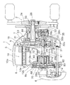
本発明の一実施形態による両軸受リールは、図1及び図2に示すように、ベイトキャスト用のロープロフィル形の両軸受リールである。このリールは、リール本体1と、リール本体1の側方に配置されたスプール回転用ハンドル2と、ハンドル2のリール本体1側に配置されたドラグ調整用のスタードラグ3とを備えている。
[Reel configuration]
The double-bearing reel according to the embodiment of the present invention is a low-profile double-bearing reel for bait casting as shown in FIGS. 1 and 2. The reel includes a reel body 1, a
ハンドル2は、アーム部2aと、アーム部2aの両端に回転自在に装着された把手2bとを有するダブルハンドル形のものであり、アーム部2aは、図2に示すように、ハンドル軸30の先端に回転不能に装着されており、ナット28によりハンドル軸30に締結されている。
The
リール本体1は、たとえばマグネシウム合金などの軽金属製の部材であり、フレーム5と、フレーム5の両側方に装着された第1側カバー6及び第2側カバー7とを有している。リール本体1の内部には糸巻き用のスプール12がスプール軸20(図2参照)を介して回転自在に装着されている。
The reel body 1 is a light metal member such as a magnesium alloy, for example, and has a
フレーム5内には、図2に示すように、スプール12と、サミングを行う場合の親指の当てとなるクラッチレバー17(図1参照)と、スプール12内に均一に釣り糸を巻くためのレベルワインド機構18とが配置されている。またフレーム5と第2側カバー7との間には、ハンドル2からの回転力をスプール12及びレベルワインド機構18に伝えるためのギア機構19と、スプール12とハンドル2との連結・遮断するクラッチ機構21と、クラッチレバー17の操作に応じてクラッチ機構21を制御するためのクラッチ制御機構22と、スプール12を制動するドラグ機構23と、スプール12の回転時の抵抗力を調整するためのキャスティングコントロール機構24とが配置されている。また、フレーム5と第1側カバー6との間には、キャスティング時のバックラッシュを抑えるための電気制御式のスプール制動機構25が配置されている。
As shown in FIG. 2, the
フレーム5は、所定の間隔をあけて互いに対向するように配置された1対の第1側板8及び第2側板9と、これらの第1側板8及び第2側板9を一体で連結する複数の連結部10aとを有している。第1側板8には、円形の開口8aが形成されている。この開口8aには、リール本体1を構成する環状部材13が着脱自在にねじ止め固定されている。環状部材13の外周部には、一部が切り欠かれた位置決め凹部13cが形成されており、図示しない第1側板8の位置決め突起に係止することで、環状部材13を所定の位置に位置決めできる。環状部材13は、ダイカスト成形により形成されたアルミニウム合金製の部材であって、その表面には、陽極酸化処理による陽極酸化被膜が形成されている。環状部材13の内周部には、後述する支持部材81が着脱自在に固定されており、支持部材81の内周側には、スプール12の一端を支持する軸受26aが収納される軸受収納部14が設けられている。
The
スプール12は、図2に示すように、両側部に皿状のフランジ部12aを有しており、両フランジ部12aの間に筒状の糸巻胴部12bを有している。図2左側のフランジ部12aの外周面は、糸噛みを防止するために開口8aの内周側に僅かな隙間をあけて配置されている。スプール12は、糸巻胴部12bの内周側を貫通するスプール軸20にたとえばセレーション結合により回転不能に固定されている。
As shown in FIG. 2, the
スプール軸20は、たとえばSUS304等の非磁性金属製であり、第2側板9を貫通して第2側カバー7の外方に延びている。その延びた一端は、第2側カバー7に装着されたボス部に軸受26bにより回転自在に支持されている。またスプール軸20の他端は軸受26aにより回転自在に支持されている。スプール軸20の中心には、大径部20aが形成されており、両端に軸受26a、26bに支持される小径部20b、20cが形成されている。なお、軸受26a、26bは転がり部材と内輪及び外輪とがSUS404C製でその表面を改質して耐食性を向上させた転がり軸受である。
The
さらに、図2左側の小径部20bと大径部20aとの間には両者の中間の外径を有する、後述する磁石61を装着するための磁石装着部20dが形成されている。磁石装着部20dには、たとえば、SUM(押出・切削)等の鉄材の表面に無電界ニッケルめっきを施した磁性体製の磁石保持部27がたとえばセレーション結合により回転不能に固定されている。磁石保持部27は、断面が正方形で中心に磁石装着部20dが貫通する貫通孔27aが形成された四角柱状の部材である。磁石保持部27の固定方法はセレーション結合に限定されず、キー結合やスプライン結合等の種々の結合方法を用いることができる。
Further, the
スプール軸20の大径部20aの右端は、第2側板9の貫通部分に配置されており、そこにはクラッチ機構21を構成する係合ピン29が固定されている。係合ピン29は、直径に沿って大径部20aを貫通しており、その両端が径方向に突出している。
A right end of the large-
クラッチレバー17は、図1に示すように、1対の第1側板8及び第2側板9の間の後部でスプール12後方に配置されている。クラッチレバー17はクラッチ制御機構22に連結されており、第1側板8及び第2側板9の間で上下方向にスライドして、クラッチ機構21を連結状態と遮断状態とに切り換える。
As shown in FIG. 1, the
ギア機構19は、ハンドル軸30と、ハンドル軸30に固定されたメインギア31と、メインギア31に噛み合う筒状のピニオンギア32とを有している。ハンドル軸30は、第2側板9及び第2側カバー7に回転自在に装着されており、ローラ型のワンウェイクラッチ86及び爪式のワンウェイクラッチ87により糸繰り出し方向の回転(逆転)が禁止されている。ワンウェイクラッチ86は、第2側カバー7とハンドル軸30との間に装着されている。メインギア31は、ハンドル軸30に回転自在に装着されており、ハンドル軸30とドラグ機構23を介して連結されている。
The
ピニオンギア32は、第2側板9の外方から内方に延び、中心にスプール軸20が貫通する筒状部材であり、スプール軸20に軸方向に移動自在に装着されている。また、ピニオンギア32の図2左端側は、軸受33により第2側板9に回転自在かつ軸方向移動自在に支持されている。ピニオンギア32の図2左端部には係合ピン29に噛み合う噛み合い溝32aが形成されている。この噛み合い溝32aと係合ピン29とによりクラッチ機構21が構成される。また中間部にはくびれ部32bが、右端部にはメインギア31に噛み合うギア部32cがそれぞれ形成されている。
The pinion gear 32 is a cylindrical member that extends inward from the outside of the
クラッチ制御機構22は、スプール軸20方向に沿って移動するクラッチヨーク35を有している。また、クラッチ制御機構22は、スプール12の糸巻き取り方向の回転に連動してクラッチ機構21をクラッチオンさせる図示しないクラッチ戻し機構を有している。
The clutch control mechanism 22 has a clutch yoke 35 that moves along the direction of the
キャスティングコントロール機構24は、スプール軸20の両端を挟むように配置された複数の摩擦プレート51と、摩擦プレート51によるスプール軸20の挟持力を調節するための制動キャップ52とを有している。左側の摩擦プレート51は、軸受収納部14内に装着されている。
The
〔スプール制動機構の構成〕
スプール制動機構25は、図5に示すように、スプール12とリール本体1とに設けられたスプール制動ユニット40と、釣り糸に作用する張力を検出するための回転速度センサ41と、スプール制動ユニット40を4つの制動モードのいずれかで電気的に制御するスプール制御ユニット42と、4つの制動モードを選択するためのモードつまみ43とを有している。
[Configuration of spool braking mechanism]
As shown in FIG. 5, the
スプール制動ユニット40は、スプール12を発電により制動する電気的に制御可能なものである。スプール制動ユニット40は、スプール軸20に回転方向に並べて配置された複数(たとえば4つ)の磁石61を含む回転子60と、回転子60の外周側に対向して配置され直列接続された複数(たとえば4つ)のコイル62と、直列接続された複数のコイル62の両端が接続されたスイッチ素子63とを備えている。スプール制動ユニット40は、磁石61とコイル62との相対回転により発生する電流を、スイッチ素子63によりオンオフすることによりデューティ比を変更してスプール12を制動する。スプール制動ユニット40で発生する制動力はスイッチ素子63のオン時間が長いほど(デューティ比が大きいほど)に強くなる。
The
回転子60の4つの磁石61は、周方向に並べて配置され極性が交互に異なっている。磁石61は、磁石保持部27と略同等の長さを有する部材であり、その外側面は断面円弧状の面であり、内側面は平面である。この内側面がスプール軸20の磁石保持部27の外周面に接触して配置されている。
The four
糸巻胴部12bの内周面の磁石61に対向する位置には、図2に示すように、たとえば、SUM(押出・切削)等の鉄材の表面に無電界ニッケルめっきを施した磁性体製のスリーブ68が装着されている。スリーブ68は、糸巻胴部12bの内周面に圧入又は接着などの適宜の固定手段により固定されている。このような磁性体製のスリーブ68を磁石61に対向して配置すると、磁石61からの磁束がコイル62を集中して通過するので、発電及びブレーキ効率が向上する。
As shown in FIG. 2, at the position facing the
コイル62は、コギングを防止してスプール12の回転をスムーズにするためにコアレスタイプのものが採用されている。さらにヨークも設けられていない。コイル62は、巻回された芯線が磁石61に対向して磁石61の磁場内に配置されるように略矩形に巻回されている。4つのコイル62は直列接続されており、その両端がスイッチ素子63に接続されている。コイル62は、磁石61の外側面との距離が略一定になるようにスプール軸芯に対して実質的に同芯の円弧状にスプール12の回転方向に沿って湾曲して成形されている。このため、コイル62と回転中の磁石61との隙間を一定に維持することができる。コイル62は、後述する回路基板70に取り付けられている
スイッチ素子63は、たとえば高速でオンオフ制御できる並列接続された2つのFET(電界効果トランジスタ)を有している。FETの各ドレイン端子に直列接続されたコイル62が接続されている。このスイッチ素子63も回路基板70に装着されている。
The
回転速度センサ41は、たとえば、投光部と受光部とを有する投受光型の光電スイッチを用いている。回路基板70に対向するスプール12のフランジ部12aの外側面には、回転方向に間隔を隔てて配置されたに複数のスリットを有する検出筒部12cが一体形成されており、回転速度センサ41は、検出筒部12cを挟んで投光部と受光部とが対向して配置され、スリットを通過する光によりスプール12の回転速度を検出している。
The
モードつまみ43は、4つの制動モードのいずれかを選択するために設けられている。4つの制動モードは、第1制動力及び第2制動力が異なる制動モードであり、Lモード(遠投モード)と、Mモード(中距離モード)と、Aモード(オールラウンドモード)と、Wモード(ウインドモード)の4つのモードである。
The
ここで、Lモードは、比重の軽い釣り糸を使用し、追い風の恵まれた条件においてスプーン、メタルジグ、バイブレーションなどの空気抵抗が少なく重い仕掛け(ルアー)を超遠投するためのロングディスタンスモードである。キャスティング直後のエネルギーを極限まで利用し、最大回転数を可能な限り高め、さらに中盤以降をほとんどフリーにして飛距離を伸ばせるように考慮された制動モードであり、第1制動力が最も小さく設定されている。 Here, the L mode is a long distance mode for using a fishing line having a low specific gravity and throwing a heavy lure having a low air resistance such as a spoon, a metal jig, and a vibration under conditions of good tailwind. It is a braking mode that takes into account the energy immediately after casting to the maximum, raises the maximum number of revolutions as much as possible, and further increases the flight distance by making most of the middle and later free, and the first braking force is set to the smallest ing.
Mモードは、重心移動式プラグやペンシルベイト、バイブレーションなど空気抵抗の少ない仕掛け(プラグ)で快適に遠投できるように設定された制動モードである。キャスティング直後のオーバーランを抑えつつ、中盤以降を上手く補正してギリギリのところでバックラッシュさせずに飛距離を伸ばせるように設定している。比重の小さいポリアミド樹脂系の釣り糸を使用する場合、このモードを基準に設定するのが好ましい。 The M mode is a braking mode that is set so that a long throw can be comfortably performed with a device (plug) having a low air resistance, such as a center-of-gravity plug, pencil bait, and vibration. While suppressing overrun immediately after casting, it has been set so that it can extend the distance without causing backlash at the last minute by correcting well after the middle stage. When using a polyamide resin fishing line having a small specific gravity, it is preferable to set this mode as a reference.
Aモードは、キャスティング直後のエネルギーを極限まで利用しつつ、後半の伸びを重視したブレーキ設定である。釣り糸や仕掛けの種類、風向きを問わず、ほとんどの状況でオールマイティーに使用可能である。特に、比重の重いフロロカーボン系の釣り糸を使用する場合、このモードを基準に設定するのが好ましい。 The A mode is a brake setting that uses the energy immediately after casting as much as possible and emphasizes the latter half of the growth. It can be used for almighty in most situations, regardless of the type of fishing line, mechanism, or wind direction. In particular, when a fluorocarbon fishing line having a high specific gravity is used, it is preferable to set this mode as a reference.
Wモードは、完全な向かい風の中で仕掛けの飛行距離が落ちる状況でもバックラッシュを可及的に抑えて飛行距離を伸ばすモードであり、第2制動力が最も大きく設定されている。飛行中に回転して減速しやすい重心固定ミノーやフラットサイドクランクを向かい風に向かって投げる場合に最適な用に設定されている。また、ピッチングやスキッピングなどのライトキャスティングであっても低回転からしっかりとバックラッシュを防止するように設定されている。 The W mode is a mode in which the flight distance is increased by suppressing backlash as much as possible even in a situation where the flight distance of the device falls in a complete headwind, and the second braking force is set to be the largest. It is set for optimal use when throwing a fixed center of gravity minnow or flat-side crank toward the wind that is easy to rotate and slow down during flight. Also, even light casting such as pitching and skipping is set to prevent backlash firmly from low rotation.
モードつまみ43は、図4に示すように、第1側カバー6に回動自在かつ制動モードに応じた4つの回転位相に位置決め可能に設けられている。モードつまみ43には、図示しない磁石が設けられている。回路基板70には、図10に示すように、磁石が回動する領域に間隔を隔てて配置された2つのホール素子からなるモードつまみ位置センサ45が設けられている。モードつまみ位置センサ45は、磁石の通過による2つのホール素子のオンオフの変化、具体的には、両方オン、一方オン他方オフ、一方オフ他方オン、両方オフにより、後述する制御部55は、モードつまみの回転位相を検出し、4つの制動モードのいずれかを回転位相に応じて設定する。
As shown in FIG. 4, the
モードつまみ43は、図4及び図11に示すように、4つの制動モードを選択するために回動操作するためのダイヤルであるつまみ部43aと、つまみ部43aが回動自在に支持されるつまみ本体43bと、つまみ部43aの先端部に固定され図示しない磁石を取り付けるための磁石取付台43cと、つまみ本体43bの裏面側に形成されつまみ部43aの回動に連動して揺動する磁石取付台43cの揺動を規制するために磁石取付台43cの側端部が当たる段差である壁部43dと、つまみ本体43bのつまみ部43aと逆側に配置され4つの凹部を有する円板状の発音円板43eと、発音円板43eの凹部に当接して発音するピン部材とばね部材からなる発音部材43fとを有している。ここでは、磁石取付台43cの揺動を規制する壁部43dをつまみ本体43bに設けたので、従来のようにつまみ部43aの先端部に壁部を設けさらにこの部分に発音機構を組み込んだときに発生したがたつきを抑えることができる。
As shown in FIGS. 4 and 11, the
スプール制御ユニット42は、支持部材81のスプール12のフランジ部12aに対向する面に装着された回路基板70と、回路基板70に搭載された制御部55とを有している。
The
回路基板70は、中心が円形に開口する座金形状のリング状の基板であり、軸受収納部14の外周側でスプール軸20と実質的に同芯に配置されている。回路基板70は、支持部材81に相対回動自在に装着されている。また、回路基板70は、開口8aに対して所定の位相で配置されるように位置決めされている。これにより、支持部材81を開口8aに固定された環状部材13に対して回して着脱しても回路基板70が一定の位相で配置される。
The
ここでは、回路基板70が支持部材81のスプール12のフランジ部12aと対向する面に装着されているので、回転子60の周囲に配置されたコイル62を回路基板70に直接取り付けることができる。このため、コイル62と回路基板70とを接続するリード線が不要になり、コイル62と回路基板70との絶縁不良を軽減できる。しかも、コイル62が支持部材81に取り付けられた回路基板70に装着されているので、回路基板70を支持部材81に取り付けるだけでコイル62も支持部材81に装着される。このため、スプール制動機構25を容易に組み立てできる。さらに、回路基板70がスプール軸部に相対回転自在に装着され、かつ開口8aに対して所定の位相に位置決めされるので、回路基板70とリール本体1との位相が変化しない。このため、開閉する第1側カバー6に装着されたモードつまみ43に磁石を設け、回路基板70にホール素子を設けても、ホール素子が磁石を常に同じ位置関係で検出できる。
Here, since the
制御部55は、たとえばCPU55a、RAM55b、ROM55c及びI/Oインターフェイス55d等が搭載されたマイクロコンピュータから構成されている。制御部55のROM55cには、制御プログラムが格納されるとともに、2つの制動処理にわたる基本制動力や補正制動力やタイマなどのデータがそれぞれ4つの制御モードに応じて格納されている。また、各制御モード時の張力の参照張力や開始張力などの設定値なども格納されている。制御部55には、回転速度センサ41と、モードつまみ43の回動位置を検出するためのモードつまみ位置センサ45とが接続されている。また、制御部55には、スイッチ素子63の各FETのゲートが接続されている。制御部55は、各センサ41、45からの入力と制御プログラムとにより、スプール制動ユニット40のスイッチ素子63をたとえば周期1/1000秒のPWM(パルス幅変調)信号によりオンオフ制御する。具体的には、制御部55は、選択された制動モードにおいて、回転速度に応じて減少するデューティ比Dでスイッチ素子63をオンオフ制御する。制御部55には電源としての蓄電素子57からの電力が供給される。この電力は回転速度センサ41とつまみ位置検出センサ45にも供給される。
The
電源としての蓄電素子57は、たとえば電解コンデンサを用いており、整流回路58に接続されている。整流回路58はスイッチ素子63に接続されており、回転子60とコイル62とを有し発電機として機能するスプール制動ユニット40からの交流電流を直流に変換しかつ電圧を安定化して蓄電素子57に供給する。
The
なお、これらの整流回路58及び蓄電素子57も回路基板70に搭載されている。この回路基板70に搭載されたコイル62を含む各部は、ホットメルトモールディング法により形成された合成樹脂絶縁体製の絶縁被膜90により覆われている。絶縁被膜90は鍔付き円筒状に形成されており、コイル62と回路基板70と回路基板70に装着された電気部品とを覆っている。ただし、回転速度センサ41の投受光部分は絶縁被膜90から露出している。
The
このようなスプール制動機構25をリール本体1に着脱可能に取り付けるために必要な両軸受リールの構成部品について説明する。
The components of the dual-bearing reel necessary for detachably attaching the
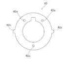
スプール制動機構25が取り付けられる両軸受リールは、図3、図4及び図6に示すように、第1側板8の開口8aに固定された環状部材13の内周部に装着される筒状部81aと筒状部81aの内側に設けられスプール軸20の端部を支持する回転支持部81bとを有する支持部材81と、筒状部81aの内側に相対回転可能に装着され回路基板70と回路基板70に装着された電気部品とコイル62とインサート部材84と絶縁被膜90とが一体的なユニットとなった基板組立体80と、筒状部81aの内側と基板組立体80の外側との間に装着され基板組立体80を支持部材81に対して軸方向に抜け止めするCリングからなる抜け止め部材83と、第1側板8の開口8aの内周部に相対回転不能に装着され内周部に雌ねじ部13a及び回り止め凹部13bが形成されたリール本体1の構成の1つである環状部材13と、回り止め凹部13bに係合する回り止め突起82cを有し基板組立体80を環状部材13に対して回り止めする回り止め部材である基板固定板82とをさらに備えている。なお、図示していないが、基板組立体80の支持部材81と対向する面には、基板組立体80の印刷面を隠蔽するためのシート部材が貼付されている。
As shown in FIGS. 3, 4, and 6, the dual-bearing reel to which the
支持部材81は、図3、図4及び図6に示すように、第1側板8の開口8aに固定された環状部材13の内周部に装着される筒状部81aと、筒状部81aの内側に設けられスプール軸20の端部を支持する回転支持部81bとを有している。筒状部81aの内周部には、周方向に沿って環状に形成された溝部81dが形成されており、基板組立体80の外周に装着されたCリングからなる抜け止め部材83が溝部81dに圧接された状態で装着される。ここでは、Cリングからなる抜け止め部材83が、基板組立体80の外周部及び溝部81dに圧接された状態で装着されるので、基板組立体80が支持部材81から軸方向に移動するのが規制されるとともに、基板組立体80が支持部材81に対して相対回転可能な状態となる。また、筒状部81aの外周部には、図4及び図6に示すように、雄ねじ部81cが形成されており、この雄ねじ部81cを環状部材13の内周部に形成されたに雌ねじ部13a(図4、図6及び図9参照)に螺合させることによって、支持部材81を環状部材13に固定できる。環状部材13は、第1側板8の開口8aの内周部に相対回転不能に図示しない3つのボルトによって固定されているので、この結果、支持部材81は第1側板8の開口8aの内周側に相対回転不能に固定される。
As shown in FIGS. 3, 4, and 6, the
基板固定板82は、図3、図4及び図6に示すように、コイル62を挿通するように基板組立体80に固定される板状部材であって、板面側に間隔をあけて3箇所に形成された第2貫通孔82aを有している。ここでは、3つの第2貫通孔82aに3つのボルトからなる固定部材85を基板組立体80のインサート部材84にねじ止めすることによって、基板組立体80に基板固定板82を相対移動不能に固定している。基板固定板82の外形は、基板組立体80の外形より大きい外形を有しており、基板組立体80を支持部材81に装着したときに、外形の大きい基板固定板82によって、基板組立体80が支持部材81装着側と逆側方向に抜けるのを防止できる。また、基板固定板82は、基板組立体80を環状部材13に対して回り止めする板状の部材であって、環状部材13の回り止め凹部13bに係合する回り止め突起82cを有している。回り止め突起82cは、図7及び図8に示すように、外周部の一部が環状部材13側に向かって略直角に折れ曲がって突出した係止片である。回り止め凹部13bは、図9に示すように、環状部材13の内周部の雌ねじ部13aの一部を切り欠いて形成された係止溝である。ここでは、基板固定板82の回り止め突起82cを環状部材13の回り止め凹部13bに係合することによって、基板固定板82と環状部材13とが回り止めされ、すなわち基板固定板82が固定された基板組立体80と、環状部材13が固定された第1側板8とが回り止めされる。
As shown in FIGS. 3, 4 and 6, the
〔スプール制動機構の着脱動作〕
このようなスプール制動機構25をリール本体1に取り付けるには、まず、環状部材13を第1側板8の開口8aに相対移動不能にねじ止め固定する。次に、基板組立体80に基板固定板82を固定部材85によってねじ止めし、基板固定板82が固定された基板組立体80を支持部材81に装着し、Cリングからなる抜け止め部材83を基板組立体80と支持部材81との間に介装することで、基板組立体80と支持部材81とを相対回転可能かつ軸方向移動不能に固定する。そして、基板組立体80、支持部材81、基板固定板82及び抜け止め部材83が一体となったユニットの状態で、基板固定板82の回り止め突起82cを環状部材13の回り止め凹部13bに係止し、支持部材81外周部の雄ねじ部81cを環状部材13内周部の雌ねじ部13aに螺合させることによって、基板組立体80、支持部材81、基板固定板82及び抜け止め部材83が一体となったユニットを環状部材13、すなわち第1側板8の開口8aの内周側に取り付けられる。
[Removal operation of spool braking mechanism]
In order to attach such a
ここでは、基板組立体80、支持部材81、基板固定板82及び抜け止め部材83が一体となったユニットをリール本体1の環状部材13に螺合させることで、スプール制動機構25をリール本体1に取り付けることができる。また、基板組立体80、支持部材81、基板固定板82及び抜け止め部材83が一体となったユニットを逆に回転させることによって、スプール制動機構25をリール本体1から取り外すことができる。
Here, the
〔実釣時のリールの操作及び動作〕
キャスティングを行うときには、クラッチレバー17を下方に押圧してクラッチ機構21をクラッチオフ状態にする。このクラッチオフ状態では、スプール12が自由回転状態になり、キャスティングを行うと仕掛けの重さにより釣り糸がスプール12から勢いよく繰り出される。このキャスティングによりスプール12が回転すると、磁石61がコイル62の内周側を回転して、スイッチ素子63をオンするとコイル62に電流が流れスプール12が制動される。キャスティング時にはスプール12の回転速度は徐々に速くなり、ピークを越えると徐々に減速する。
[Operation and operation of reel during actual fishing]
When casting, the
仕掛けが着水すると、ハンドル2を糸巻き取り方向に回転させて図示しないクラッチ戻し機構によりクラッチ機構21をクラッチオン状態にし、リール本体1をパーミングしてアタリを待つ。
When the device reaches the ground, the
このようなスプール制動機構25では、基板組立体80を支持部材81に装着し、Cリングからなる抜け止め部材83を基板組立体80と支持部材81との間に介装することで、基板組立体80と支持部材81とを相対回転可能かつ軸方向移動不能に固定するようになっている。ここでは、基板組立体80と支持部材81とは、Cリングからなる抜け止め部材83によって一体的なユニットになっているので、支持部材81を取り外すだけで支持部材81と一体となった基板組立体80も同時に取り外すことができる。したがって、従来のように複数のねじ部材を基板組立体80から着脱することなく、基板組立体80の着脱を容易に行うことができる。
In such a
〔他の実施形態〕
(a) 前記実施形態では、ベイトキャスト用のロープロフィル形の両軸受リールを例にあげて説明したが、丸形の両軸受リールであってもよい。
[Other Embodiments]
(A) In the above embodiment, a bayocast low profile double-bearing reel has been described as an example, but a round double-bearing reel may be used.
(b) 前記実施形態では、発電によりスプールを制動するスプール制動ユニットを開示したが、スプール制動ユニットは、電気的に制御可能なものであればどのような構成でもよい。たとえば、電気的に制御可能なアクチュエータによりブレーキシューやブレーキパッドをドラムやディスクに接触させるようなものでもよい。 (B) In the above-described embodiment, the spool braking unit that brakes the spool by power generation is disclosed. However, the spool braking unit may have any configuration as long as it is electrically controllable. For example, a brake shoe or a brake pad may be brought into contact with a drum or a disk by an electrically controllable actuator.
(c) 前記実施形態では、モードつまみ位置センサ45として、2つのホール素子を用いていたが、ホール素子に代えて、リードスイッチを用いる構成にしてもよい。
(C) In the embodiment, two Hall elements are used as the mode
(d) 前記実施形態では、第1側板8の開口8aに環状部材13が着脱可能に装着されていたが、環状部材13を設けずに、支持部材81を第1側板8の開口8aに着脱可能に装着するようにしてもよい。たとえば、図示しないが、第1側板8の開口8aの内周部に雌ねじ部を形成し、この雌ねじ部に支持部材81の外周部に形成された雄ねじ部81cを螺合するようにしてもよい。
(D) In the above embodiment, the
(e) 前記実施形態では、環状部材13の1つの回り止め凹部13bに基板固定板82の1つの回り止め突起82cを係合させていたが、図12及び図13に示すように、環状部材13の複数(図13では2つ)の回り止め凹部13bに基板固定板82の複数(図12では2つ)の回り止め突起82cを係合させてもよい。
(E) In the above-described embodiment, one
(f) 前記実施形態では、環状部材13の回り止め凹部13bに基板固定板82の回り止め突起82cを係合させていたが、図14及び図15に示すように、環状部材13の回り止め突起13d(図15参照)を基板固定板82の回り止め凹部82d(図14参照)に係合させてもよい。なお、環状部材13の回り止め突起13dは、雌ねじ部13aの螺合を阻害しないように、雌ねじ部13aの終端部分にのみ突出するように形成されている。
(F) In the above-described embodiment, the
(g) 前記実施形態では、抜け止め部材83として、Cリングを用いたが、図16に示すように、Oリングからなる抜け止め部材88であってもよい。
(G) In the embodiment, as a
1 リール本体
5 フレーム
6 第1側カバー
7 第2側カバー
8 第1側板
9 第2側板
12 スプール
13 環状部材
13a 雌ねじ部
13b 回り止め凹部
13c 位置決め凹部
13d 回り止め突起
20 スプール軸
25 スプール制動機構
27 磁石保持部
40 スプール制動ユニット
42 スプール制御ユニット
43 モードつまみ
43a つまみ部
43b つまみ本体
43c 磁石取付台
43d 壁部
43e 発音円板
43f 発音部材
45 モードつまみ位置センサ
55 制御部
60 回転子
61 磁石
62 コイル
63 スイッチ素子
70 回路基板
70a 第1貫通孔
80 基板組立体
81 支持部材
81a 筒状部
81b 回転支持部
81c 雄ねじ部
81d 溝部
82 基板固定板
82a 第2貫通孔
82c 回り止め突起
82d 回り止め凹部
83 抜け止め部材
84 インサート部材
85 固定部材
88 抜け止め部材
90 絶縁被膜
DESCRIPTION OF SYMBOLS 1
82c
85 Fixing member
8 8
Claims (9)
前記釣竿に装着され、側部に開口を有するリール本体と、
前記リール本体に回転可能に支持され、前記釣り糸を外周に巻き取るスプールと、
前記スプールを制動するスプール制動手段と、
前記リール本体の前記開口に装着される筒状部と、前記筒状部の内側に設けられ前記スプールの回転軸を支持する回転支持部とを有する支持部材と、
前記筒状部の内側に相対回転可能に装着され、前記スプール制動手段を制御する電気回路が載置された基板組立体と、
前記筒状部の内側と前記基板組立体の外側との間に装着され、前記基板組立体を前記支持部材に対して抜け止めする抜け止め部材と、
を備えた両軸受リール。 A dual-bearing reel that is attached to a fishing rod and feeds and winds the fishing line,
A reel body mounted on the fishing rod and having an opening on the side;
A spool that is rotatably supported by the reel body, and winds the fishing line around an outer periphery;
Spool braking means for braking the spool;
A support member having a cylindrical part mounted in the opening of the reel body, and a rotation support part provided inside the cylindrical part and supporting a rotation shaft of the spool;
A substrate assembly mounted on the inner side of the tubular portion so as to be relatively rotatable, and on which an electric circuit for controlling the spool braking means is mounted;
A retaining member that is mounted between the inside of the tubular portion and the outside of the substrate assembly, and that prevents the substrate assembly from being detached from the support member;
Double-bearing reel equipped with.
前記回り止め部材は、前記回り止め凹部に係合する回り止め突起を有している、請求項3に記載の両軸受リール。 The reel body has a detent recess formed in the opening;
The dual bearing reel according to claim 3, wherein the rotation prevention member has a rotation prevention projection that engages with the rotation prevention recess.
前記回り止め部材は、前記回り止め突起が係合する回り止め凹部を有している、請求項3に記載の両軸受リール。 The reel body has a detent projection formed in the opening,
The dual bearing reel according to claim 3, wherein the rotation prevention member has a rotation prevention concave portion with which the rotation prevention protrusion is engaged.
前記抜け止め部材は、前記基板組立体の外周部及び前記溝部に装着されるリング部材である、請求項1から6のいずれか1項に記載の両軸受リール。 The support member has a groove formed in an annular shape on the inner periphery of the cylindrical portion,
The dual-bearing reel according to claim 1, wherein the retaining member is a ring member that is attached to an outer peripheral portion and a groove portion of the substrate assembly.
前記支持部材は、前記筒状部の外周部に形成され、前記雌ねじ部に螺合する雄ねじ部を有している、請求項1から7のいずれか1項に記載の両軸受リール。 The reel body has a female thread portion formed on the inner periphery of the opening,
The dual bearing reel according to any one of claims 1 to 7, wherein the support member has a male screw portion formed on an outer peripheral portion of the cylindrical portion and screwed into the female screw portion.
Priority Applications (4)
| Application Number | Priority Date | Filing Date | Title |
|---|---|---|---|
| JP2007340401A JP4926037B2 (en) | 2007-12-28 | 2007-12-28 | Double bearing reel |
| TW097140003A TWI436734B (en) | 2007-12-28 | 2008-10-17 | Double bearing reel |
| CN2008101705767A CN101467522B (en) | 2007-12-28 | 2008-10-23 | Dual-bearing fishing reel |
| KR1020080113223A KR101403929B1 (en) | 2007-12-28 | 2008-11-14 | Dual bearing reel |
Applications Claiming Priority (1)
| Application Number | Priority Date | Filing Date | Title |
|---|---|---|---|
| JP2007340401A JP4926037B2 (en) | 2007-12-28 | 2007-12-28 | Double bearing reel |
Publications (3)
| Publication Number | Publication Date |
|---|---|
| JP2009159849A JP2009159849A (en) | 2009-07-23 |
| JP2009159849A5 JP2009159849A5 (en) | 2011-01-06 |
| JP4926037B2 true JP4926037B2 (en) | 2012-05-09 |
Family
ID=40825515
Family Applications (1)
| Application Number | Title | Priority Date | Filing Date |
|---|---|---|---|
| JP2007340401A Active JP4926037B2 (en) | 2007-12-28 | 2007-12-28 | Double bearing reel |
Country Status (4)
| Country | Link |
|---|---|
| JP (1) | JP4926037B2 (en) |
| KR (1) | KR101403929B1 (en) |
| CN (1) | CN101467522B (en) |
| TW (1) | TWI436734B (en) |
Families Citing this family (13)
| Publication number | Priority date | Publication date | Assignee | Title |
|---|---|---|---|---|
| JP5528244B2 (en) | 2010-07-26 | 2014-06-25 | 東京エレクトロン株式会社 | Plasma processing method and storage medium |
| JP6166558B2 (en) * | 2013-03-13 | 2017-07-19 | 株式会社シマノ | Double bearing reel |
| US9832983B2 (en) * | 2014-07-16 | 2017-12-05 | Shimano Inc. | Dual-bearing reel |
| JP6559036B2 (en) * | 2015-10-06 | 2019-08-14 | 株式会社シマノ | Double bearing reel |
| JP7008454B2 (en) * | 2017-09-28 | 2022-01-25 | 株式会社シマノ | Double bearing reel |
| JP7064316B2 (en) * | 2017-11-10 | 2022-05-10 | 株式会社シマノ | Double bearing reel |
| JP7064323B2 (en) * | 2017-12-06 | 2022-05-10 | 株式会社シマノ | Bearing holding structure of fishing reel and fishing reel |
| JP7015690B2 (en) * | 2017-12-27 | 2022-02-03 | 株式会社シマノ | Fishing reel switch |
| JP7122167B2 (en) * | 2018-06-11 | 2022-08-19 | シマノコンポネンツ マレーシア エスディーエヌ.ビーエッチディー. | Double bearing reel |
| JP7121569B2 (en) * | 2018-07-13 | 2022-08-18 | 株式会社シマノ | Double bearing reel |
| CN111642473B (en) * | 2020-06-15 | 2022-05-03 | 威海良美精密机械有限公司 | Fishing reel with hydraulic brake structure |
| JP7374056B2 (en) * | 2020-08-27 | 2023-11-06 | グローブライド株式会社 | fishing reel |
| CN113207825B (en) * | 2021-04-30 | 2022-03-15 | 北京邮电大学 | Automatic installation device of guide ring for fishing rod |
Family Cites Families (11)
| Publication number | Priority date | Publication date | Assignee | Title |
|---|---|---|---|---|
| JPH0717064U (en) * | 1993-09-14 | 1995-03-28 | ダイワ精工株式会社 | Backlash prevention device for dual-bearing reels for fishing |
| US5636804A (en) * | 1993-10-05 | 1997-06-10 | Bando Leports, Ltd. | Double-bearing fishing reel |
| JP3495252B2 (en) * | 1998-03-30 | 2004-02-09 | ダイワ精工株式会社 | Fishing reel |
| JP4173244B2 (en) * | 1999-03-30 | 2008-10-29 | 株式会社シマノ | Double bearing reel |
| JP3955725B2 (en) * | 2000-11-10 | 2007-08-08 | ダイワ精工株式会社 | Double bearing reel for fishing |
| CN1454468A (en) * | 2002-05-01 | 2003-11-12 | 株式会社岛野 | Double-bearing fish-line wheel |
| JP4039951B2 (en) * | 2003-01-06 | 2008-01-30 | 株式会社シマノ | Double bearing reel braking device |
| JP2004215531A (en) * | 2003-01-10 | 2004-08-05 | Shimano Inc | Double bearing reel |
| JP2006197810A (en) * | 2005-01-18 | 2006-08-03 | Shimano Inc | Spool braking device of double bering reel |
| JP4916696B2 (en) * | 2005-10-13 | 2012-04-18 | シマノコンポネンツ マレーシア エスディーエヌ.ビーエッチディー. | Double bearing reel |
| JP2008182915A (en) * | 2007-01-29 | 2008-08-14 | Daiwa Seiko Inc | Reel for fishing |
-
2007
- 2007-12-28 JP JP2007340401A patent/JP4926037B2/en active Active
-
2008
- 2008-10-17 TW TW097140003A patent/TWI436734B/en active
- 2008-10-23 CN CN2008101705767A patent/CN101467522B/en active Active
- 2008-11-14 KR KR1020080113223A patent/KR101403929B1/en active IP Right Grant
Also Published As
| Publication number | Publication date |
|---|---|
| TW200934382A (en) | 2009-08-16 |
| KR20090072950A (en) | 2009-07-02 |
| JP2009159849A (en) | 2009-07-23 |
| KR101403929B1 (en) | 2014-06-09 |
| CN101467522B (en) | 2012-02-01 |
| TWI436734B (en) | 2014-05-11 |
| CN101467522A (en) | 2009-07-01 |
Similar Documents
| Publication | Publication Date | Title |
|---|---|---|
| JP4926037B2 (en) | Double bearing reel | |
| JP6072422B2 (en) | Double bearing reel | |
| JP2009159849A5 (en) | ||
| JP4785499B2 (en) | Spool braking device for double-bearing reel | |
| JP6085447B2 (en) | Spool braking device for double-bearing reel | |
| KR101007837B1 (en) | Braking device for a dual bearing reel | |
| US20090166459A1 (en) | Spool brake device of dual-bearing reel | |
| JP2007135417A5 (en) | ||
| JP2014082938A5 (en) | ||
| JP2006197810A (en) | Spool braking device of double bering reel | |
| JP2006197810A5 (en) | ||
| JP4039951B2 (en) | Double bearing reel braking device | |
| JP2014082937A (en) | Spool braking device for double-bearing reel | |
| JP4926036B2 (en) | Electronic equipment for fishing gear | |
| JP2009159848A5 (en) | ||
| JP2009159850A (en) | Spool brake device of double bearing reel | |
| JP2012050398A (en) | Dual-bearing reel | |
| JP3977746B2 (en) | Double bearing reel braking device | |
| JP3977748B2 (en) | Double bearing reel braking device | |
| JP3977747B2 (en) | Double bearing reel braking device | |
| JP2006230358A (en) | Dual-bearing reel |
Legal Events
| Date | Code | Title | Description |
|---|---|---|---|
| A521 | Request for written amendment filed |
Free format text: JAPANESE INTERMEDIATE CODE: A523 Effective date: 20101116 |
|
| A621 | Written request for application examination |
Free format text: JAPANESE INTERMEDIATE CODE: A621 Effective date: 20101116 |
|
| A977 | Report on retrieval |
Free format text: JAPANESE INTERMEDIATE CODE: A971007 Effective date: 20111226 |
|
| TRDD | Decision of grant or rejection written | ||
| A01 | Written decision to grant a patent or to grant a registration (utility model) |
Free format text: JAPANESE INTERMEDIATE CODE: A01 Effective date: 20120131 |
|
| A01 | Written decision to grant a patent or to grant a registration (utility model) |
Free format text: JAPANESE INTERMEDIATE CODE: A01 |
|
| A61 | First payment of annual fees (during grant procedure) |
Free format text: JAPANESE INTERMEDIATE CODE: A61 Effective date: 20120207 |
|
| FPAY | Renewal fee payment (event date is renewal date of database) |
Free format text: PAYMENT UNTIL: 20150217 Year of fee payment: 3 |
|
| R150 | Certificate of patent or registration of utility model |
Ref document number: 4926037 Country of ref document: JP Free format text: JAPANESE INTERMEDIATE CODE: R150 Free format text: JAPANESE INTERMEDIATE CODE: R150 |
|
| R250 | Receipt of annual fees |
Free format text: JAPANESE INTERMEDIATE CODE: R250 |
|
| R250 | Receipt of annual fees |
Free format text: JAPANESE INTERMEDIATE CODE: R250 |
|
| R250 | Receipt of annual fees |
Free format text: JAPANESE INTERMEDIATE CODE: R250 |
|
| R250 | Receipt of annual fees |
Free format text: JAPANESE INTERMEDIATE CODE: R250 |
|
| R250 | Receipt of annual fees |
Free format text: JAPANESE INTERMEDIATE CODE: R250 |
|
| R250 | Receipt of annual fees |
Free format text: JAPANESE INTERMEDIATE CODE: R250 |
|
| R250 | Receipt of annual fees |
Free format text: JAPANESE INTERMEDIATE CODE: R250 |
|
| R250 | Receipt of annual fees |
Free format text: JAPANESE INTERMEDIATE CODE: R250 |
|
| R250 | Receipt of annual fees |
Free format text: JAPANESE INTERMEDIATE CODE: R250 |
|
| R250 | Receipt of annual fees |
Free format text: JAPANESE INTERMEDIATE CODE: R250 |