JP4923562B2 - Air bag and air bag device - Google Patents
Air bag and air bag device Download PDFInfo
- Publication number
- JP4923562B2 JP4923562B2 JP2005368280A JP2005368280A JP4923562B2 JP 4923562 B2 JP4923562 B2 JP 4923562B2 JP 2005368280 A JP2005368280 A JP 2005368280A JP 2005368280 A JP2005368280 A JP 2005368280A JP 4923562 B2 JP4923562 B2 JP 4923562B2
- Authority
- JP
- Japan
- Prior art keywords
- panel
- airbag
- chamber
- occupant
- tether belt
- Prior art date
- Legal status (The legal status is an assumption and is not a legal conclusion. Google has not performed a legal analysis and makes no representation as to the accuracy of the status listed.)
- Expired - Fee Related
Links
Images


Classifications
-
- B—PERFORMING OPERATIONS; TRANSPORTING
- B60—VEHICLES IN GENERAL
- B60R—VEHICLES, VEHICLE FITTINGS, OR VEHICLE PARTS, NOT OTHERWISE PROVIDED FOR
- B60R21/00—Arrangements or fittings on vehicles for protecting or preventing injuries to occupants or pedestrians in case of accidents or other traffic risks
- B60R21/02—Occupant safety arrangements or fittings, e.g. crash pads
- B60R21/16—Inflatable occupant restraints or confinements designed to inflate upon impact or impending impact, e.g. air bags
- B60R21/23—Inflatable members
- B60R21/231—Inflatable members characterised by their shape, construction or spatial configuration
- B60R21/2334—Expansion control features
- B60R21/2338—Tethers
- B60R2021/23382—Internal tether means
Description
本発明は、車両衝突時等に乗員を保護するためのエアバッグ及びエアバッグ装置に係り、特に、乗員の前方の左側及び右側においてそれぞれ膨張する左室及び右室を有し、該左室と右室との間に上下方向に凹条が形成されるエアバッグと、このエアバッグを備えたエアバッグ装置に関する。 The present invention relates to an airbag and an airbag apparatus for protecting an occupant in a vehicle collision or the like, and in particular, has a left chamber and a right chamber that are inflated on the left and right sides in front of the occupant, The present invention relates to an airbag in which a concave line is formed in the vertical direction between the right ventricle and an airbag device including the airbag.
車両衝突時等に乗員を保護するためのエアバッグとして、乗員の前方の左側及び右側においてそれぞれ膨張する左半側エアバッグ及び右半側エアバッグを有し、これらが共通のインフレータによって膨張するよう構成されたエアバッグが、特開2004−244006号公報に記載されている。 As airbags for protecting the occupant in the event of a vehicle collision, etc., there are a left half airbag and a right half airbag that are inflated on the left and right sides in front of the occupant, respectively, and these are inflated by a common inflator A configured airbag is described in Japanese Patent Application Laid-Open No. 2004-244006.
このエアバッグは、折り畳まれてケース内に収容され、リッドやインパネによって覆われている。車両衝突時にインフレータ(ガス発生器)がガス噴出作動すると、エアバッグはリッドやインパネを押し開けつつ乗員の前方に膨張する。 The airbag is folded and accommodated in a case, and is covered with a lid or an instrument panel. When the inflator (gas generator) operates to eject gas at the time of a vehicle collision, the airbag is inflated forward of the occupant while pushing open the lid and the instrument panel.
膨張したエアバッグの乗員対向面には、左室と右室との間に、エアバッグの上面から下面にまで凹条が延在する。
上記特開2004−244006号公報のエアバッグにあっては、凹条が280〜480mm程度と深いので、エアバッグの表面積が大きく、エアバッグを構成するパネル(布)の量が多く必要となり、材料コスト高であった。 In the airbag of the above Japanese Patent Application Laid-Open No. 2004-244006, since the recess is as deep as about 280 to 480 mm, the surface area of the airbag is large, and a large amount of panel (cloth) constituting the airbag is required. The material cost was high.
本発明は、左室と右室との間に上下方向に凹条が延在するように膨張するエアバッグのパネル使用量を少量化することを目的とする。 An object of the present invention is to reduce the panel usage of an airbag that is inflated so that a concave line extends in the vertical direction between the left ventricle and the right ventricle.
請求項1のエアバッグは、インフレータからガスが供給される前室(2)と、それぞれ該前室(2)に連なり、該前室(2)からガスが導入され、乗員前方の左側において膨張する左室(3)及び乗員前方の右側において膨張する右室(4)とを備え、膨張状態にあっては、該左室(3)と右室(4)との間に、エアバッグの上面側から下面部にまで連続して延在する凹条(6)が形成されるエアバッグにおいて、該エアバッグ内に、該凹条(6)の最深部の少なくとも一部をエアバッグ内に引き込むためのテザーベルト(7)が設けられているエアバッグであって、該エアバッグは、該左室(3)の左側の外向き面、該右室(4)の右側の外向き面、及び該前室(2)の外面を構成する第1のパネル(10)と、該左室(3)の該凹条(6)に臨む面を構成する第2のパネル(20)と、該右室(4)の該凹条(6)に臨む面を構成する第3のパネル(20)と、該テザーベルト(7)とを縫合することにより構成されたものであり、該第1のパネル(10)の乗員側の辺の左右方向の中央部には、該乗員側から切り込まれた形状のU字状の湾入部(13)が形成されており、乗員と反対側の辺の左右方向の中央部には、該乗員側に凹んだ方形の切込部(14)が形成されており、該第1のパネル(10)のうち、該湾入部(13)と切込部(14)との間の部分は、該前室(2)の底面を構成する前室底面構成部(12)となっており、該前室底面構成部(12)の左右に、それぞれ、該左室(3)の外向き面並びに前室(2)の左側面及び上面を構成する左側半部(11)と、該右室(4)の外向き面並びに前室(2)の右側面及び上面を構成する右側半部(11)とが連なっており、該第1のパネル(10)は、該切込部(14)の奥側の奥辺部(14a)と、該切込部(14)の左右の側辺部(14b,14b)とが縫合され、且つ該左側半部(11)及び右側半部(11)の乗員と反対側の辺(11a,11a)同士が縫合されており、これにより、該第1のパネル(10)は半開殻状となっており、該第2のパネル(20)及び第3のパネル(20)は、それぞれ、乗員側に向って凸に湾曲した長弧辺(21)と、該長弧辺(21)に対向しており、該乗員側に向って凹に湾曲した短弧辺(22)とを有した弓形のものとなっており、該第2のパネル(20)の長弧辺(21)が該左側半部(11)の外縁辺(11b)に縫合され、該第3のパネル(20)の長弧辺(21)が該右側半部(11)の外縁辺(11b)に縫合され、且つ該第2のパネル(20)と第3のパネル(20)との短弧辺(22,22)同士が縫合されており、これにより、該左室(3)及び右室(4)の乗員側面と、これらの間において該エアバッグの上面側から下面部まで連続して延在する凹条(6)とが形成されており、該短弧辺(22,22)同士の縫合部が該凹条(6)の最深部となっており、前記テザーベルト(7)は、1対の平たい帯面を有した帯状のものであり、該テザーベルト(7)は、該帯面の延在方向を該短弧辺(22,22)同士の縫合部の延在方向と平行方向として、その一端側が該短弧辺(22,22)同士の縫合部に縫着され、他端側が前記湾入部(13)の最奥部(13a)に縫着されており、該テザーベルト(7)の該一端側は、該凹条(6)の最深部のうち上下方向の中間付近又は上部に連なっていることを特徴とするものである。
Inflation air bag according to
請求項2のエアバッグは、請求項1において、前記短弧辺(E)に耳状の取付片(Fa,Fb)が設けられており、該取付片(Fa,Fb)に前記テザーベルト(7)の端部が縫着されていることを特徴とするものである。
請求項3のエアバッグは、請求項2において、前記短弧辺(E)の一端側及び他端側にそれぞれ前記取付片(Fa,Fb)が設けられており、これらの取付片(Fa,Fb)に前記テザーベルト(7)の一端側及び他端側がそれぞれ縫着されていることを特徴とするものである。
請求項4のエアバッグは、請求項1ないし3のいずれか1項において、前記第1のパネル(10)は、実質的に、前記左側半部(11)及び右側半部(11)をそれぞれ構成する2枚のアウターパネル(30,30)と、実質的に、前記前室底面構成部(12)を構成するセンターパネル(40)とを縫合してなるものであることを特徴とするものである。
The airbag according to
The airbag according to
The airbag according to claim 4 is the airbag according to any one of
請求項5のエアバッグは、請求項1ないし4のいずれか1項において、膨張したエアバッグの最乗員側を通る水平断面における凹条(6)の深さが10〜280mmであることを特徴とするものである。
The airbag according to
請求項6のエアバッグ装置は、請求項1ないし5のいずれか1項に記載のエアバッグと、該エアバッグを膨張させるためのインフレータとを備えたことを特徴とする。 An airbag device according to a sixth aspect includes the airbag according to any one of the first to fifth aspects, and an inflator for inflating the airbag.
本発明では、膨張したエアバッグの左室が乗員の左胸を受け止め、右室が右胸を受け止め、乗員の胸の左右方向の中央部及び頭部には、膨張したエアバッグの凹条が対峙する。 In the present invention, the left ventricle of the inflated airbag receives the left chest of the occupant, the right chamber receives the right chest, and the left and right central portions and the head of the occupant's chest have the indentations of the inflated airbag. Confront.
本発明では、左室と右室との間の凹条の少なくとも一部をテザーベルトでエアバッグ内部に引き込むようにしているため、凹条が浅くなるようにパネルを設計しても、凹条深さを大きくとることができる。 In the present invention, since at least a part of the groove between the left ventricle and the right ventricle is drawn into the airbag by the tether belt, even if the panel is designed so that the groove is shallow, the groove depth It can take a large size.
本発明では、凹条を浅くすることにより、エアバッグの表面積を小さくし、パネルの必要量を減少させることができる。 In the present invention, by making the recesses shallow, the surface area of the airbag can be reduced and the required amount of the panel can be reduced.
凹条の上部ないし中間部付近をエアバッグ内部に引き込むことにより、乗員の頭部ないし胸中央部に対峙する凹条深さを大きくすることができる。 By pulling the upper part or the vicinity of the middle part of the concave line into the airbag, the depth of the concave line facing the occupant's head or the center of the chest can be increased.
本発明では、膨張したエアバッグの最乗員側を通る水平断面における凹条の深さが10〜280mm特に50〜200mmであることが好ましい。 In this invention, it is preferable that the depth of the groove in the horizontal cross section passing through the most occupant side of the inflated airbag is 10 to 280 mm, particularly 50 to 200 mm.
以下、図面を参照して本発明の実施の形態について説明する。 Embodiments of the present invention will be described below with reference to the drawings.
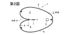
第1図は本発明の実施の形態に係る助手席用エアバッグの膨張状態における斜視図、第2図は第1図のII−II線断面図であり、第3図はこのエアバッグの分解斜視図である。また、第4図は、このエアバッグを構成するパネルの平面図である。 1 is a perspective view of the passenger airbag according to the embodiment of the present invention in an inflated state, FIG. 2 is a cross-sectional view taken along the line II-II of FIG. 1, and FIG. 3 is an exploded view of the airbag. It is a perspective view. FIG. 4 is a plan view of a panel constituting the airbag.
このエアバッグ1は、乗員から見て最も前方側に位置する前室2と、該前室2に連なり、乗員前方の左側において膨張する左室3と、乗員前方の右側において膨張する右室4とを有する。前室2の底面部にインフレータの装着口5が設けられている。
The
第1図に示すように、このエアバッグ1が膨張した状態にあっては、左室3と右室4の先端部同士の間にタイパネルなどの架渡部材は存在せず、左室3と右室4の先端部同士に間に形成される凹条6は乗員に向って開放し、エアバッグ1の上部から下部まで連続して延在している。この凹条6の最深部は、上下方向の途中が乗員に向って突出するように湾曲している。
As shown in FIG. 1, when the
この凹条6の最深部の上部とエアバッグ1の底部との間にテザーベルト7が架設され、これにより、凹条6の上部がエアバッグ1内に引き込まれるよう構成されている。左室3及び右室4はベントホール8を介してエアバッグ1外に連通している。
A
このエアバッグ1は、第3,4図の通り、メインパネル10と、2枚のインサイドパネル20とで構成されている。
The
第4図の通り、メインパネル10は、前室底面構成部12を介して連なる左右の半部11を有する。このメインパネル10の乗員側には、乗員側から切り込まれた形状の略々U字状の湾入部13が形成されると共に、乗員と反対側には方形の切込部14が設けられている。
As shown in FIG. 4, the
この切込部14の奥辺部14aと左右の側辺部14b,14bとが縫合される。一方の半部11の前室2側の縁辺11aと他方の半部11の前室2側の縁辺11aとが縫合されると、メインパネル10は半開殻状となり、これにより、エアバッグ1の左室3及び右室4の外向き面と、前室2の外面とが構成される。
The
各インサイドパネル20は、長弧辺21と短弧辺22とを有した略弓形である。各インサイドパネル20の長弧辺21が各半部11,11の外縁辺11bに縫合され、各インサイドパネル20の短弧辺22,22同士が縫合されることにより、エアバッグ1の乗員対向面が構成される。
Each
第3図の通り、テザーベルト7の一端は、インサイドパネル20,20の上部における短弧辺22同士の縫合部に対し縫着され、テザーベルト7の他端は、湾入部13の最奥部13aに縫合される。
As shown in FIG. 3, one end of the
このエアバッグ1と、該エアバッグ1を膨張させるためのインフレータと、エアバッグ1を収容したケースと、該ケースを覆うリッド又はインパネ(インストルメントパネル)によってエアバッグ装置が構成される。このエアバッグ装置は、エアバッグがインパネ背後側に位置するように自動車に設置される。
An airbag device is constituted by the
インフレータが作動することにより、エアバッグ1が第1図の通り膨張する。乗員の左胸は左室3に受け止められ、乗員の右胸は右室4に受け止められ、頭部は凹条6に入り込んで受け止められる。
When the inflator is activated, the
このエアバッグ1にあっては、膨張した状態において最乗員側の先端部を含む水平断面における凹条6の深さ(ほぼ第2図のDに相当する。)は10〜280mm特に50〜200mm程度であることが好ましい。
In the
このエアバッグ1は、凹条6が比較的浅いので、エアバッグ1の表面積が小さく、パネル10,20,20の合計の面積が小さい。このため、パネル材料コストが安価である。また、縫合長さも比較的短くて済む。このエアバッグ1では、凹条6が浅いが、凹条6の上部はテザーベルト7によってエアバッグ1内に引き込まれており、乗員頭部を受け止めるのに適した形状となっている。
In the
上記実施の形態では、凹条6の最深部(インサイドパネル20,20の短弧片22同士の縫合部)の上部をテザーベルト7によってエアバッグ1内に引き込むようにしているが、凹条6の上下方向の中間付近や下部をエアバッグ1内に引き込むようにテザーベルト7の連結位置を変えてもよい。(例えば、テザーベルト7の前記他端側はインフレータ装着口5付近に連結されてもよい。)また、凹条6の上下方向の複数箇所をテザーベルトによってエアバッグ1内に引き込むようにしてもよい。
In the above embodiment, the upper part of the deepest portion of the concave strip 6 (the stitched portion between the
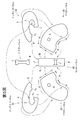
第5図は、別の実施の形態に係るエアバッグを構成するパネルの平面図であり、第6図(a)はこのエアバッグの上面図、第6図(b)は第6図(a)のB−B線に沿う断面図である。 FIG. 5 is a plan view of a panel constituting an airbag according to another embodiment, FIG. 6 (a) is a top view of the airbag, and FIG. 6 (b) is FIG. 6 (a). It is sectional drawing which follows the BB line of ().
前述の実施の形態では、エアバッグ1の左室3及び右室4の外向き面と、前室2の外面とが1枚のメインパネル10により構成されているが、この実施の形態のエアバッグ1Aにあっては、これらが別々のパネルにより構成されている。
In the above-described embodiment, the outward facing surfaces of the
以下に、このエアバッグ1Aのパネル構成について説明する。 Below, the panel structure of this airbag 1A is demonstrated.
このエアバッグ1Aは、2枚のアウターパネル30と、1枚のセンターパネル40と、2枚のインサイドパネル50と、1本のテザーベルト7とからなる。
The
各アウターパネル30は、実質的に、前述の実施の形態におけるメインパネル10の左右の各半部11に相当するものであり、センターパネル40は、実質的に、前室底面構成部12に相当するものである。該センターパネル40には、縫製後のエアバッグ1Aの前室2の底面部に位置するように、インフレータ装着口5’が設けられている。
Each
各アウターパネル30のうち、前室2の左右の側面を構成する領域の周縁部(第5図の辺AからA’にかけて)が、センターパネル40の左右の側辺BL,BRにそれぞれ縫合される。これにより、パネル30,40,30が、第3図のメインパネル10の如き半開殻状の連続体となり、エアバッグ1Aの左室3及び右室4の外向き面と前室2の外面とが構成される。
Of the
各インサイドパネル50は、前述の実施の形態におけるインサイドパネル20と同様の、長弧辺Cと短弧辺Eとを有した略弓形のものである。該短弧辺Eの一端側及び他端側には、テザーベルト7の一端側及び他端側がそれぞれ取り付けられる耳状の取付片Fa,Fbが設けられている。
Each
各インサイドパネル50の長弧辺Cが各アウターパネル30の外縁辺Gに縫合され、各インサイドパネル50の短弧辺E,E同士が縫合される。また、各インサイドパネル50の上端辺Hがセンターパネル40の上端辺Jに縫合されると共に、各インサイドパネル50の下端辺Iがセンターパネル40の下端辺Kに縫合される。これにより、エアバッグ1Aの乗員対向面が構成される。この乗員対向面は、第6図(a)の通り、乗員側へ向って開放した凹条6を構成する。
The long arc side C of each
第6図(b)に示すように、テザーベルト7の一端側(第5図の端部L)が各インサイドパネル50の上端側の取付片Faに縫い付けられ、他端側(第5図の端部M)が各インサイドパネル50の下端側の取付片Fbに縫い付けられている。なお、各インサイドパネル50の上端側の取付片Faは,下端側の取付片Fbよりも前室2の奥側(前方)に位置しており、各インサイドパネル50の下端側(凹条6の下端側の最奥部)は、テザーベルト7を介して該前室2の奥側へ引張られることとなる。
As shown in FIG. 6 (b), one end side (end L in FIG. 5) of the
このエアバッグ1Aにあっても、膨張した状態において最乗員側の先端部を含む水平断面における凹条6の深さ(ほぼ第6図(a)のDに相当する。)が10〜280mm特に50〜200mm程度となるよう構成されている。 Even in the airbag 1A, in the inflated state, the depth of the concave strip 6 in the horizontal cross section including the tip portion on the most occupant side (corresponding to D in FIG. 6 (a)) is particularly 10 to 280 mm. It is comprised so that it may become about 50-200 mm.
このエアバッグ1A及びこのエアバッグ1Aを備えたエアバッグ装置のその他の構成は前述の実施の形態と同様であり、第5,6図において第1〜4図と同一符号は同一部分を示している。 Other configurations of the airbag 1A and the airbag apparatus including the airbag 1A are the same as those of the above-described embodiment. In FIGS. 5 and 6, the same reference numerals as those in FIGS. 1 to 4 denote the same parts. Yes.
このエアバッグ1Aも、前述の実施の形態のエアバッグ1と同様の作用効果を奏する。
This airbag 1A also has the same effects as the
この実施の形態では、エアバッグ1Aを構成するパネルを比較的細かく分割しているので、例えば1枚の基布から、その余白部分を埋めるようにして複数のパネルを効率良く製作することも可能であり、これによりエアバッグ1Aにかかる材料コストを一層抑えることができる。 In this embodiment, since the panels constituting the airbag 1A are relatively finely divided, for example, it is possible to efficiently produce a plurality of panels from one base cloth so as to fill the blank portion. Thus, the material cost for the airbag 1A can be further reduced.
上記実施の形態は本発明の一例であり、本発明は図示以外の形態をもとりうる。 The above embodiment is an example of the present invention, and the present invention may take forms other than those shown in the drawings.
例えば、膨張したエアバッグ1,1Aの左右幅を規制するように左右方向に延在するテザーベルトを設けてもよい。
For example, a tether belt extending in the left-right direction may be provided so as to regulate the left-right width of the
本発明のエアバッグのパネル構成は、上記の各実施の形態のパネル構成に限定されるものではない。 The panel configuration of the airbag of the present invention is not limited to the panel configuration of each of the above embodiments.
1,1A エアバッグ
2 前室
3 左室
4 右室
6 凹条
7 テザーベルト
10 メインパネル
20 インサイドパネル
30 アウターパネル
40 センターパネル
50 インサイドパネル
1,
Claims (6)
それぞれ該前室(2)に連なり、該前室(2)からガスが導入され、乗員前方の左側において膨張する左室(3)及び乗員前方の右側において膨張する右室(4)と
を備え、
膨張状態にあっては、該左室(3)と右室(4)との間に、エアバッグの上面側から下面部にまで連続して延在する凹条(6)が形成されるエアバッグにおいて、
該エアバッグ内に、該凹条(6)の最深部の少なくとも一部をエアバッグ内に引き込むためのテザーベルト(7)が設けられているエアバッグであって、
該エアバッグは、該左室(3)の左側の外向き面、該右室(4)の右側の外向き面、及び該前室(2)の外面を構成する第1のパネル(10)と、該左室(3)の該凹条(6)に臨む面を構成する第2のパネル(20)と、該右室(4)の該凹条(6)に臨む面を構成する第3のパネル(20)と、該テザーベルト(7)とを縫合することにより構成されたものであり、
該第1のパネル(10)の乗員側の辺の左右方向の中央部には、該乗員側から切り込まれた形状のU字状の湾入部(13)が形成されており、乗員と反対側の辺の左右方向の中央部には、該乗員側に凹んだ方形の切込部(14)が形成されており、
該第1のパネル(10)のうち、該湾入部(13)と切込部(14)との間の部分は、該前室(2)の底面を構成する前室底面構成部(12)となっており、該前室底面構成部(12)の左右に、それぞれ、該左室(3)の外向き面並びに前室(2)の左側面及び上面を構成する左側半部(11)と、該右室(4)の外向き面並びに前室(2)の右側面及び上面を構成する右側半部(11)とが連なっており、
該第1のパネル(10)は、該切込部(14)の奥側の奥辺部(14a)と、該切込部(14)の左右の側辺部(14b,14b)とが縫合され、且つ該左側半部(11)及び右側半部(11)の乗員と反対側の辺(11a,11a)同士が縫合されており、これにより、該第1のパネル(10)は半開殻状となっており、
該第2のパネル(20)及び第3のパネル(20)は、それぞれ、乗員側に向って凸に湾曲した長弧辺(21)と、該長弧辺(21)に対向しており、該乗員側に向って凹に湾曲した短弧辺(22)とを有した弓形のものとなっており、
該第2のパネル(20)の長弧辺(21)が該左側半部(11)の外縁辺(11b)に縫合され、該第3のパネル(20)の長弧辺(21)が該右側半部(11)の外縁辺(11b)に縫合され、且つ該第2のパネル(20)と第3のパネル(20)との短弧辺(22,22)同士が縫合されており、これにより、該左室(3)及び右室(4)の乗員側面と、これらの間において該エアバッグの上面側から下面部まで連続して延在する凹条(6)とが形成されており、該短弧辺(22,22)同士の縫合部が該凹条(6)の最深部となっており、
前記テザーベルト(7)は、1対の平たい帯面を有した帯状のものであり、
該テザーベルト(7)は、該帯面の延在方向を該短弧辺(22,22)同士の縫合部の延在方向と平行方向として、その一端側が該短弧辺(22,22)同士の縫合部に縫着され、他端側が前記湾入部(13)の最奥部(13a)に縫着されており、
該テザーベルト(7)の該一端側は、該凹条(6)の最深部のうち上下方向の中間付近又は上部に連なっていることを特徴とするエアバッグ。 An anterior chamber (2) to which gas is supplied from the inflator;
Each includes a left chamber (3 ) that is connected to the front chamber (2) and into which gas is introduced from the front chamber (2) and expands on the left side in front of the occupant and a right chamber (4) that expands on the right side in front of the occupant. ,
In the inflated state, an air gap is formed between the left ventricle (3) and the right ventricle (4) to form a recess (6) extending continuously from the upper surface side to the lower surface portion of the airbag. In the bag,
The airbag is provided with a tether belt (7) for drawing at least a part of the deepest portion of the recess (6) into the airbag,
The airbag is a first panel (10) that constitutes a left outward surface of the left chamber (3), a right outward surface of the right chamber (4), and an outer surface of the front chamber (2). And a second panel (20) constituting a surface of the left chamber (3) facing the recess (6), and a second panel (20) of the right chamber (4) forming a surface facing the recess (6). 3 is constructed by stitching the panel (20) and the tether belt (7),
A U-shaped baying portion (13) cut from the occupant side is formed at the center of the side of the occupant side of the first panel (10), and is opposite to the occupant. A square notch (14) that is recessed toward the occupant is formed in the lateral center of the side edge.
Of the first panel (10), the portion between the bay entrance (13) and the notch (14) is a front chamber bottom surface constituting portion (12) that constitutes the bottom surface of the front chamber (2). The left half (11) constituting the outward facing surface of the left chamber (3), the left side surface and the upper surface of the front chamber (2), respectively, on the left and right sides of the front chamber bottom surface component (12). And the right side half (11) constituting the outward surface of the right chamber (4) and the right side and top surface of the front chamber (2),
The first panel (10) has a back side (14a) on the back side of the cut portion (14) and left and right side sides (14b, 14b) of the cut portion (14). And the sides (11a, 11a) opposite to the occupant of the left half (11) and the right half (11) are stitched together, whereby the first panel (10) is a half-open shell. And
The second panel (20) and the third panel (20) are respectively opposed to the long arc side (21) curved convexly toward the occupant side and the long arc side (21), It has an arcuate shape with a short arc side (22) curved concavely toward the occupant side,
The long arc side (21) of the second panel (20) is stitched to the outer edge side (11b) of the left half (11), and the long arc side (21) of the third panel (20) is Stitched to the outer edge (11b) of the right half (11) and the short arc sides (22, 22) of the second panel (20) and the third panel (20) are stitched together; Thereby, the occupant side surfaces of the left ventricle (3) and the right ventricle (4) and the concave line (6) extending continuously from the upper surface side to the lower surface portion of the airbag are formed between them. And the seam between the short arc sides (22, 22) is the deepest part of the recess (6),
The tether belt (7) is a belt having a pair of flat belt surfaces,
The tether belt (7) has the extending direction of the belt surface parallel to the extending direction of the stitched portion between the short arc sides (22, 22), and one end side of the tether belt (22, 22) is between the short arc sides (22, 22). The other end side is sewn to the innermost part (13a) of the bay portion (13),
The airbag according to claim 1, wherein the one end side of the tether belt (7) is connected to the middle or upper part in the vertical direction of the deepest part of the recess (6) .
Priority Applications (4)
| Application Number | Priority Date | Filing Date | Title |
|---|---|---|---|
| JP2005368280A JP4923562B2 (en) | 2005-11-10 | 2005-12-21 | Air bag and air bag device |
| PCT/JP2006/322260 WO2007055234A1 (en) | 2005-11-10 | 2006-11-08 | Airbag and airbag device |
| EP06823164.6A EP1905657B1 (en) | 2005-11-10 | 2006-11-08 | Airbag and airbag device |
| US12/091,533 US7841622B2 (en) | 2005-11-10 | 2006-11-08 | Airbag and airbag apparatus |
Applications Claiming Priority (3)
| Application Number | Priority Date | Filing Date | Title |
|---|---|---|---|
| JP2005326324 | 2005-11-10 | ||
| JP2005326324 | 2005-11-10 | ||
| JP2005368280A JP4923562B2 (en) | 2005-11-10 | 2005-12-21 | Air bag and air bag device |
Publications (2)
| Publication Number | Publication Date |
|---|---|
| JP2007153290A JP2007153290A (en) | 2007-06-21 |
| JP4923562B2 true JP4923562B2 (en) | 2012-04-25 |
Family
ID=38023236
Family Applications (1)
| Application Number | Title | Priority Date | Filing Date |
|---|---|---|---|
| JP2005368280A Expired - Fee Related JP4923562B2 (en) | 2005-11-10 | 2005-12-21 | Air bag and air bag device |
Country Status (4)
| Country | Link |
|---|---|
| US (1) | US7841622B2 (en) |
| EP (1) | EP1905657B1 (en) |
| JP (1) | JP4923562B2 (en) |
| WO (1) | WO2007055234A1 (en) |
Families Citing this family (12)
| Publication number | Priority date | Publication date | Assignee | Title |
|---|---|---|---|---|
| USRE46909E1 (en) | 2006-09-22 | 2018-06-26 | Autoliv Development Ab | Manufacturing method of airbag cushion, and the airbag cushion |
| JP4853408B2 (en) * | 2007-07-06 | 2012-01-11 | トヨタ自動車株式会社 | Airbag device |
| JP5402218B2 (en) * | 2008-12-19 | 2014-01-29 | タカタ株式会社 | Air bag, air bag device and vehicle |
| KR101071740B1 (en) * | 2009-07-31 | 2011-10-11 | 기아자동차주식회사 | Front passebger air bag for vehicles |
| JP5362501B2 (en) * | 2009-09-18 | 2013-12-11 | タカタ株式会社 | Air bag and air bag device |
| JP5327385B2 (en) * | 2010-06-04 | 2013-10-30 | トヨタ自動車株式会社 | Passenger airbag |
| US8439399B2 (en) | 2010-07-30 | 2013-05-14 | Ford Global Technologies | Airbag with tethered slit |
| US8944462B2 (en) * | 2011-04-15 | 2015-02-03 | Trw Vehicle Safety Systems Inc. | Air bag with uninflated pocket |
| JP6224915B2 (en) * | 2013-05-20 | 2017-11-01 | タカタ株式会社 | Air bag and air bag device |
| DE102014001506B4 (en) * | 2014-02-06 | 2019-05-29 | Trw Automotive Gmbh | Front airbag |
| CN112706719B (en) * | 2019-10-25 | 2024-04-09 | 奥托立夫开发公司 | Airbag and vehicle |
| KR102589936B1 (en) * | 2020-12-01 | 2023-10-17 | 현대모비스 주식회사 | Air bag cushion for a vehicle |
Family Cites Families (20)
| Publication number | Priority date | Publication date | Assignee | Title |
|---|---|---|---|---|
| JPS4923176B1 (en) * | 1970-09-24 | 1974-06-13 | ||
| JPS4923176A (en) | 1972-06-26 | 1974-03-01 | ||
| US7234560B2 (en) * | 1994-04-19 | 2007-06-26 | Applied Elastomerics, Inc. | Inflatable restraint cushions and other uses |
| JP3760424B2 (en) | 1996-08-30 | 2006-03-29 | 本田技研工業株式会社 | Airbag device for vehicle |
| DE20005755U1 (en) * | 2000-03-29 | 2000-08-10 | Trw Repa Gmbh | Gas bag |
| EP1164060B1 (en) | 2000-06-16 | 2005-12-28 | TRW Automotive Safety Systems GmbH | Airbag protection device for a vehicle passenger |
| DE20022020U1 (en) | 2000-12-28 | 2001-11-08 | Trw Automotive Safety Sys Gmbh | Airbag module |
| US7093853B2 (en) | 2003-01-23 | 2006-08-22 | Takata Corporation | Airbag, airbag device and vehicle |
| JP4367120B2 (en) * | 2003-01-23 | 2009-11-18 | タカタ株式会社 | Passenger seat airbag, passenger seat airbag apparatus and vehicle |
| US6969086B2 (en) | 2003-01-23 | 2005-11-29 | Takata Corporation | Airbag and airbag device |
| US7152877B2 (en) | 2003-01-24 | 2006-12-26 | Takata Corporation | Airbag and airbag apparatus |
| US7121584B2 (en) | 2003-01-24 | 2006-10-17 | Takata Corporation | Airbag and airbag apparatus |
| JP4380315B2 (en) * | 2003-04-03 | 2009-12-09 | タカタ株式会社 | Air bag, air bag device and vehicle |
| JP4134752B2 (en) | 2003-02-26 | 2008-08-20 | タカタ株式会社 | Air bag and air bag device |
| JP2005162195A (en) * | 2003-11-07 | 2005-06-23 | Takata Corp | Airbag cushion with slanted recess |
| DE20317614U1 (en) | 2003-11-14 | 2004-04-01 | Trw Automotive Safety Systems Gmbh | airbag |
| JP4158709B2 (en) * | 2004-01-27 | 2008-10-01 | 豊田合成株式会社 | Airbag device for passenger seat |
| US7455317B2 (en) * | 2004-09-09 | 2008-11-25 | Toyoda Gosei Co., Ltd. | Airbag for front passenger's seat |
| US20060186656A1 (en) * | 2005-02-22 | 2006-08-24 | Takata Corporation | Airbag cushion |
| US7152880B1 (en) * | 2005-10-17 | 2006-12-26 | Key Safety Systems, Inc. | Grooved air bag |
-
2005
- 2005-12-21 JP JP2005368280A patent/JP4923562B2/en not_active Expired - Fee Related
-
2006
- 2006-11-08 WO PCT/JP2006/322260 patent/WO2007055234A1/en active Application Filing
- 2006-11-08 EP EP06823164.6A patent/EP1905657B1/en not_active Expired - Fee Related
- 2006-11-08 US US12/091,533 patent/US7841622B2/en not_active Expired - Fee Related
Also Published As
| Publication number | Publication date |
|---|---|
| US7841622B2 (en) | 2010-11-30 |
| EP1905657A4 (en) | 2012-12-19 |
| JP2007153290A (en) | 2007-06-21 |
| US20090115177A1 (en) | 2009-05-07 |
| EP1905657A1 (en) | 2008-04-02 |
| WO2007055234A1 (en) | 2007-05-18 |
| EP1905657B1 (en) | 2014-01-08 |
Similar Documents
| Publication | Publication Date | Title |
|---|---|---|
| JP4923562B2 (en) | Air bag and air bag device | |
| JP4400188B2 (en) | Air bag, air bag device and vehicle | |
| US10994692B2 (en) | Frontal airbag | |
| EP1897763B1 (en) | Airbag, airbag apparatus, and motor vehicle | |
| US7862073B2 (en) | Split top air bag assembly | |
| US7695012B2 (en) | Airbag systems with a split pocket | |
| US20060103118A1 (en) | Twin airbag | |
| US7934747B2 (en) | Airbag, airbag device, and vehicle | |
| JP2006008105A (en) | Side airbag device | |
| JP2003175793A (en) | Occupant's knee protection device for vehicle | |
| JP2005145225A (en) | Passenger protecting device, and vehicle | |
| US11066037B2 (en) | Frontal airbag | |
| JP6582872B2 (en) | Passenger leg restraining device | |
| JP6146521B2 (en) | Air bag and air bag device | |
| JP7043010B2 (en) | Passenger seat airbag device | |
| US8419049B2 (en) | Airbag and airbag device | |
| JP5790354B2 (en) | Passenger seat airbag, passenger seat airbag apparatus and vehicle | |
| JP4835316B2 (en) | Air bag and air bag device | |
| WO2020044914A1 (en) | Front passenger's seat airbag | |
| CN101223057A (en) | Airbag and airbag device | |
| JP2007055327A (en) | Airbag and airbag device | |
| JP2008195215A (en) | Airbag and airbag device | |
| JP2019018591A (en) | Air bag and air bag device | |
| JP2019151172A (en) | Airbag and airbag device | |
| JP2007055328A (en) | Airbag device |
Legal Events
| Date | Code | Title | Description |
|---|---|---|---|
| A621 | Written request for application examination |
Free format text: JAPANESE INTERMEDIATE CODE: A621 Effective date: 20081119 |
|
| A131 | Notification of reasons for refusal |
Free format text: JAPANESE INTERMEDIATE CODE: A131 Effective date: 20110510 |
|
| A521 | Written amendment |
Free format text: JAPANESE INTERMEDIATE CODE: A523 Effective date: 20110617 |
|
| TRDD | Decision of grant or rejection written | ||
| A01 | Written decision to grant a patent or to grant a registration (utility model) |
Free format text: JAPANESE INTERMEDIATE CODE: A01 Effective date: 20120110 |
|
| A01 | Written decision to grant a patent or to grant a registration (utility model) |
Free format text: JAPANESE INTERMEDIATE CODE: A01 |
|
| A61 | First payment of annual fees (during grant procedure) |
Free format text: JAPANESE INTERMEDIATE CODE: A61 Effective date: 20120123 |
|
| FPAY | Renewal fee payment (event date is renewal date of database) |
Free format text: PAYMENT UNTIL: 20150217 Year of fee payment: 3 |
|
| R150 | Certificate of patent or registration of utility model |
Ref document number: 4923562 Country of ref document: JP Free format text: JAPANESE INTERMEDIATE CODE: R150 Free format text: JAPANESE INTERMEDIATE CODE: R150 |
|
| R250 | Receipt of annual fees |
Free format text: JAPANESE INTERMEDIATE CODE: R250 |
|
| R250 | Receipt of annual fees |
Free format text: JAPANESE INTERMEDIATE CODE: R250 |
|
| R250 | Receipt of annual fees |
Free format text: JAPANESE INTERMEDIATE CODE: R250 |
|
| R250 | Receipt of annual fees |
Free format text: JAPANESE INTERMEDIATE CODE: R250 |
|
| S111 | Request for change of ownership or part of ownership |
Free format text: JAPANESE INTERMEDIATE CODE: R313113 |
|
| S343 | Written request for registration of root pledge or change of root pledge |
Free format text: JAPANESE INTERMEDIATE CODE: R316354 |
|
| SZ02 | Written request for trust registration |
Free format text: JAPANESE INTERMEDIATE CODE: R316Z02 |
|
| S343 | Written request for registration of root pledge or change of root pledge |
Free format text: JAPANESE INTERMEDIATE CODE: R316354 |
|
| R350 | Written notification of registration of transfer |
Free format text: JAPANESE INTERMEDIATE CODE: R350 |
|
| S343 | Written request for registration of root pledge or change of root pledge |
Free format text: JAPANESE INTERMEDIATE CODE: R316354 |
|
| SZ02 | Written request for trust registration |
Free format text: JAPANESE INTERMEDIATE CODE: R316Z02 |
|
| R350 | Written notification of registration of transfer |
Free format text: JAPANESE INTERMEDIATE CODE: R350 |
|
| LAPS | Cancellation because of no payment of annual fees |