JP4921035B2 - Image forming apparatus - Google Patents
Image forming apparatus Download PDFInfo
- Publication number
- JP4921035B2 JP4921035B2 JP2006136357A JP2006136357A JP4921035B2 JP 4921035 B2 JP4921035 B2 JP 4921035B2 JP 2006136357 A JP2006136357 A JP 2006136357A JP 2006136357 A JP2006136357 A JP 2006136357A JP 4921035 B2 JP4921035 B2 JP 4921035B2
- Authority
- JP
- Japan
- Prior art keywords
- fixing device
- image
- unit
- driving
- fixing
- Prior art date
- Legal status (The legal status is an assumption and is not a legal conclusion. Google has not performed a legal analysis and makes no representation as to the accuracy of the status listed.)
- Expired - Fee Related
Links
Images


Landscapes
- Fixing For Electrophotography (AREA)
Description
本発明は、画像形成装置に関し、特に、電子写真プロセス方式を用いた複写機或いはプリンタ等の画像形成装置において、記録材(以下、転写材と記す)上に形成したトナー画像を転写材上に加熱定着する画像加熱定着装置を備える画像形成装置に関する。 The present invention relates to an image forming apparatus, and in particular, in an image forming apparatus such as a copying machine or a printer using an electrophotographic process method, a toner image formed on a recording material (hereinafter referred to as a transfer material) is formed on the transfer material. The present invention relates to an image forming apparatus provided with an image heat fixing device for heat fixing.
従来の技術では、定着器の交換は一般的に以下の観点から行われていた。 In the prior art, replacement of the fixing device is generally performed from the following viewpoints.
(1)所定の通紙枚数に達した場合
(2)所定の駆動積算時間を超えた場合
(3)定着ベルト(もしくはローラ)の表面性が劣化した時点
しかしながら、前記従来技術では以下の点が懸念される。 However, there are concerns about the following points in the prior art.
(1)定着器が寿命に達していなくても、所定枚数あるいは所定時間を超えたら、定着器を交換するため、ランニングコストを低減することができない。 (1) Even if the fixing device has not reached the end of its service life, the running cost cannot be reduced because the fixing device is replaced when the predetermined number or the predetermined time is exceeded.
(2)表面性の劣化により駆動トルクが増大していても、所定枚数あるいは所定時間を超えていないと交換にならないため、周辺のメカ機構にダメージを与える場合がある。 (2) Even if the driving torque is increased due to the deterioration of the surface property, the replacement is not performed unless the predetermined number of sheets or the predetermined time is exceeded, so that the surrounding mechanical mechanisms may be damaged.
本発明は、以上の点に着目して成されたもので、定着器への過負荷によるメカ機構へのダメージを防止し、限界まで定着器を使用することでランニングコストを低減することが可能になる画像形成装置を提供することを目的とする。 The present invention has been made paying attention to the above points, and prevents damage to the mechanical mechanism due to overload on the fixing device, and it is possible to reduce the running cost by using the fixing device to the limit. An object of the present invention is to provide an image forming apparatus.
本発明では、定着器の寿命を所定の通紙枚数や積算時間で判断するだけでなく、定着器の駆動負荷を測定し、その負荷の値によって定着器の寿命を判断する。また、負荷測定のタイミングとして、負荷変動の大きい通紙時以外(画像調整中、後回転など)に定着器における駆動負荷を検出し(定着モータの駆動電流を検出)、メカ機構にダメージを与える直前の負荷に達すると定着器の寿命であると判断する。これにより、過負荷によるメカ機構へのダメージを防止し、限界まで定着器を使用することでランニングコストを低減することが可能になる。 In the present invention, not only the life of the fixing device is determined by a predetermined number of sheets to be passed and the accumulated time, but also the driving load of the fixing device is measured, and the life of the fixing device is determined by the value of the load. Also, as a load measurement timing, the driving load in the fixing device is detected (detecting the driving current of the fixing motor) at times other than when a large load fluctuation is passed (during image adjustment, post-rotation, etc.), and the mechanical mechanism is damaged. When the last load is reached, it is determined that the life of the fixing device is reached. Thereby, it is possible to prevent damage to the mechanical mechanism due to overload and reduce the running cost by using the fixing device to the limit.
すなわち、本発明の技術内容は以下の構成を備えることにより前記課題を解決できた。 That is, the technical contents of the present invention can solve the above-described problems by including the following configuration.
(1)トナー像が形成された記録材を定着するための回転体と、前記回転体と圧接してニップ部を形成する加圧回転体と、前記回転体および前記加圧回転体を回転駆動する回転駆動手段と、前記回転駆動手段の駆動負荷を測定する駆動負荷測定手段とを有し、前記ニップ部で前記記録材を挟持搬送して該記録材上の画像を定着する画像定着装置を備える画像形成装置において、前記回転体と前記加圧回転体により前記ニップ部が形成され前記駆動負荷が変動しない非通紙期間に前記駆動負荷測定手段により該駆動負荷を測定し、測定した該駆動負荷の値が第一の所定値より大きい場合には前記画像定着装置の交換時期であると判断する交換時期判断手段と、前記画像定着装置の通紙枚数を計測する第一の計測手段と、前記画像定着装置の駆動積算時間を計測する第二の計測手段と、を備え、前記交換時期判断手段は、前記駆動負荷測定手段により測定した駆動負荷の値が前記第一の所定値以下で且つ第二の所定値以上である場合に、前記第一の計測手段により計測された通紙枚数が所定枚数より多い又は前記第二の計測手段により計測された駆動積算時間が所定時間より長い場合には前記画像定着装置の交換時期であると判断することを特徴とする画像形成装置。 (1) A rotating body for fixing a recording material on which a toner image is formed, a pressure rotating body that presses against the rotating body to form a nip portion, and the rotational body and the pressure rotating body are driven to rotate. And an image fixing device for fixing the image on the recording material by sandwiching and transporting the recording material at the nip portion. In the image forming apparatus, the driving load is measured by the driving load measuring means during the non-sheet passing period in which the nip portion is formed by the rotating body and the pressing rotating body and the driving load does not vary, and the driving is measured. An exchange time determination means for determining that it is the replacement time of the image fixing device when a load value is greater than a first predetermined value; a first measurement means for measuring the number of sheets of the image fixing device; Driving the image fixing device It includes a second measuring means for measuring the computation time, and the replacement timing determination means, wherein the driving load values of the driving load measured by the measuring means is equal to or less than the first predetermined value and second predetermined value or more In the case where the number of sheets passed by the first measuring unit is greater than a predetermined number or the accumulated driving time measured by the second measuring unit is longer than a predetermined time, the image fixing device an image forming apparatus comprising that you determined that the replacement timing.
本発明によれば、定着器への過負荷によるメカ機構へのダメージを防止し、限界まで定着器を使用することでランニングコストを低減することが可能になり、画像形成装置の使用状況にあわせた寿命判断を行うことができるようになる。 According to the present invention, to prevent damage to the mechanical structure due to overloading the fuser This will allow for some possible to reduce the running cost by using the fixing device to the limit, the usage of the image forming apparatus It is possible to make a lifespan judgment .
以下本発明を実施するための最良の形態を、実施例により詳しく説明する。 Hereinafter, the best mode for carrying out the present invention will be described in detail with reference to examples.
以下、本発明に係る画像形成装置を図面に則して更に詳しく説明する。 The image forming apparatus according to the present invention will be described below in more detail with reference to the drawings.
図1は、本発明の画像形成装置の一実施例に係る電子写真カラー複写機の全体構成を示す概略構成断面図である。本実施例の電子写真カラー複写機は、本発明が特に有効に適用されると考えられる、複数の画像形成部を並列に配し、且つ中間転写方式を採用したカラー画像出力装置である。 FIG. 1 is a schematic sectional view showing the overall configuration of an electrophotographic color copying machine according to an embodiment of the image forming apparatus of the present invention. The electrophotographic color copying machine of the present embodiment is a color image output apparatus in which a plurality of image forming units are arranged in parallel and an intermediate transfer method is adopted, which is considered to be applied particularly effectively.
本実施例にて、電子写真カラー複写機は、画像読取部1Rと、画像出力部1Pとを有する。画像読取部1Rは、原稿画像を光学的に読み取り、電気信号に変換して画像出力部1Pに送信する。画像出力部1Pは、複数の、本実施例では4つ並設された画像形成部10(10a、10b、10c、10d)と、給紙ユニット20とを有する。また、中間転写ユニット30と、定着ユニット40(画像定着装置に相当)と、クリーニングユニット50と、クリーニングブレード70と、フォトセンサ60と、制御ユニット80とを有する。
In this embodiment, the electrophotographic color copying machine has an
更に、個々のユニットについて詳しく説明する。 Further, each unit will be described in detail.
各画像形成部10(10a、10b、10c、10d)は同じ構成とされる。各画像形成部10(10a、10b、10c、10d)では、第一の像担持体としてのドラム状の電子写真感光体、即ち、感光体ドラム11(11a、11b、11c、11d)が回転自在に軸支され、矢印方向に回転駆動される。感光体ドラム11a〜11dの外周面に対向してその回転方向に一次帯電器12(12a、12b、12c、12d)、光学系13(13a、13b、13c、13d)が配置されている。また、折り返しミラー16(16a、16b、16c、16d)、現像装置14(14a、14b、14c、14d)、およびクリーニング装置15(15a、15b、15c、15d)が配置されている。 Each image forming unit 10 (10a, 10b, 10c, 10d) has the same configuration. In each image forming unit 10 (10a, 10b, 10c, 10d), a drum-shaped electrophotographic photosensitive member as a first image carrier, that is, a photosensitive drum 11 (11a, 11b, 11c, 11d) is freely rotatable. And is rotationally driven in the direction of the arrow. A primary charger 12 (12a, 12b, 12c, 12d) and an optical system 13 (13a, 13b, 13c, 13d) are arranged in the rotational direction opposite to the outer peripheral surfaces of the photosensitive drums 11a to 11d. Further, a folding mirror 16 (16a, 16b, 16c, 16d), a developing device 14 (14a, 14b, 14c, 14d), and a cleaning device 15 (15a, 15b, 15c, 15d) are arranged.
一次帯電器12a〜12dにおいて感光体ドラム11a〜11dの表面に均一な帯電量の電荷を与える。次いで、光学系13a〜13dにより、記録画像信号出力部でもある画像読取部1Rからの記録画像信号に応じて変調した、例えばレーザビームなどの光線を、折り返しミラー16a〜16dを介して感光体ドラム11a〜11d上に露光する。これにより、感光体ドラム11a〜11d上に静電潜像を形成する。
In the
更に、イエロー、シアン、マゼンタ、ブラックといった4色の現像剤(以下、「トナー」という)をそれぞれ収納した現像装置14a〜14dによって上記静電潜像を顕像化する。顕像化された可視画像を画像転写領域Ta、Tb、Tc、Tdにて中間転写ユニット30を構成する第二の像担持体としてのベルト状の中間転写体、即ち、中間転写ベルト31に転写する。中間転写ユニット30については、後で詳述する。
Further, the electrostatic latent images are visualized by developing
画像転写領域Ta、Tb、Tc、Tdの下流側では、クリーニング装置15a、15b、15c、15dにより中間転写ベルト31に転写されずに感光体ドラム11a〜11d上に残されたトナーを掻き落としてドラム表面の清掃を行う。以上に示したプロセスにより、各トナーによる画像形成が順次行われる。
On the downstream side of the image transfer areas Ta, Tb, Tc, and Td, the toner remaining on the photosensitive drums 11a to 11d without being transferred to the
給紙ユニット20は、転写材Pを収納するためのカセット21と、カセット21より転写材Pを一枚ずつ送り出すためのピックアップローラ22とを有する。ここで、本実施例ではカセット21のみ図示したが、カセットは複数あっても、また手差し用のトレイがあってもよい。また、ピックアップローラ22から送り出された転写材Pを更に搬送するための給紙ローラ対23と、給紙ガイド24とを有する。そして、各画像形成部10(10a、10b、10c、10d)の画像形成タイミングに合わせて転写材Pを二次転写領域Teへ送り出すためのレジストローラ25を有する。
The paper feeding unit 20 includes a
中間転写ユニット30について詳細に説明する。
The
中間転写ベルト31は、中間転写ベルト31に駆動を伝達する駆動ローラ32と、中間転写ベルト31の回動に従動する従動ローラ33と、二次転写対向ローラ34との間に張設巻回されている。ここで、従動ローラ33は、ばね(図示せず)の付勢によって中間転写ベルト31に適度なテンションを与えるテンションローラとしての役割を果たす。また、駆動ローラ32と従動ローラ33の間に一次転写平面Aが形成される。中間転写ベルト31としては、例えばPET(ポリエチレンテレフタレート)、PVdF(ポリフッ化ビニリデン)などが用いられる。駆動ローラ32は、金属ローラの表面に数mm厚のゴム(ウレタンまたはクロロプレン)をコーティングして中間転写ベルト31とのスリップを防いでいる。駆動ローラ32は、パルスモータ(不図示)によって回転駆動される。
The
各感光体ドラム11a〜11dと中間転写ベルト31が対向する一次転写領域Ta〜Tdには、中間転写ベルト31の裏に一次転写用帯電器35(35a〜35d)が配置されている。一方、二次転写対向ローラ34に対向して二次転写ローラ36が配置され、中間転写ベルト31とのニップによって二次転写領域Teを形成する。二次転写ローラ36は、中間転写ベルト31に対して適度な圧力で加圧されている。
Primary transfer chargers 35 (35 a to 35 d) are disposed on the back of the
また、中間転写ベルト31の二次転写領域Teの下流には中間転写ベルト31の画像形成面をクリーニングするためのクリーニングユニット50が配置される。クリーニングユニット50は、中間転写ベルト31上のトナーを除去するためのクリーニングブレード52と、廃トナーを収納する廃トナーボックス53とを備えている。
A cleaning unit 50 for cleaning the image forming surface of the
また、中間転写ベルト31の従動ローラ33と二次転写対向ローラ34の間にはクリーニングブレード70と、クリーニングブレード70を転写ベルト31から着脱するためのパルスモータ(不図示)が備えられている。このクリーニングブレード70も転写ベルト31上のトナーを除去するためのものである。
A
定着ユニット40は、内部にハロゲンヒーターなどの熱源を備えた定着ローラ41aと、そのローラに加圧される加圧ローラ41b(このローラにも熱源を備える場合もある)とを有する。定着ローラ41aと加圧ローラ41bは不図示の圧解除ユニットにより離間することが可能である(図2参照)。更に、上記ローラ対41a、41bのニップ部へ転写材Pを導くためのガイド26、定着ユニット40の熱を内部に閉じ込めるための定着断熱カバー51a、51bを備えている。また、上記ローラ対41a、41bから排出されてきた転写材Pをさらに画像形成装置外部に導き出すための内排紙ローラ27、外排紙ローラ28、および、転写材Pを積載する排紙トレイ29などを備えている。
The
次に、上記構成の電子写真カラー複写機の動作について説明する。 Next, the operation of the electrophotographic color copying machine having the above configuration will be described.
制御ユニット80のCPUにより画像形成動作開始信号が発せられると、選択された用紙サイズなどにより選択された給紙段から給紙動作を開始する。
When an image forming operation start signal is issued by the CPU of the
例えば、本実施例におけるカセット21から給紙された場合について説明すると、図1にて、先ず、ピックアップローラ22により、カセット21から転写材Pが一枚ずつ送り出される。そして、給紙ローラ対23によって転写材Pが給紙ガイド24の間を案内されてレジストローラ25まで搬送される。その時レジストローラ25は停止されており、転写材Pの先端はニップ部に突き当たる。その後、画像形成部10が画像の形成を開始するタイミングに合わせてレジストローラ25は回転を始める。この回転時期は、転写材Pと画像形成部10より中間転写ベルト31上に一次転写されたトナー画像とが二次転写領域Teにおいて一致するようにそのタイミングが設定されている。
For example, the case where paper is fed from the
一方、画像形成部10では、画像形成動作開始信号が発せられると、前述したプロセスにより画像形成動作が開始される。すなわち、中間転写ベルト31の回転方向(矢印B)において一番上流にある感光体ドラム11d上に形成されたトナー画像が、高電圧が印加された一次転写用帯電器35dによって一次転写領域Tdにおいて中間転写ベルト31に一次転写される。一次転写されたトナー像は次の一次転写領域Tcまで搬送される。そこでは各画像形成部間をトナー像が搬送される時間だけ遅延して画像形成が行われており、前画像の上にレジストを合わせて、その次のトナー像が転写される。以下も同様の工程が繰り返され、結局4色のトナー像が中間転写ベルト31上において一次転写される。
On the other hand, when the image forming operation start signal is issued, the
その後、転写材Pが二次転写領域Teに進入し、中間転写ベルト31に接触すると、転写材Pの通過タイミングに合わせて二次転写ローラ36に高電圧を印加する。これにより、前述したプロセスにより中間転写ベルト31上に形成された4色のトナー画像が転写材Pの表面に転写される。その後、転写材Pは搬送ガイド26によって定着ローラニップ部まで正確に案内される。そして、ローラ対41a、41bの熱およびニップの圧力によってトナー画像が転写材P表面に定着される。その後、内外排紙ローラ27、28により搬送され、転写材Pは画像形成装置外に排出され、排紙トレイ29に積載される。
Thereafter, when the transfer material P enters the secondary transfer region Te and contacts the
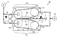
図2は定着ユニット40の横断面側面模式図である。
FIG. 2 is a schematic cross-sectional side view of the fixing
定着ユニット40は、定着器に搬送されてくる(矢印X方向)トナー像tが形成された転写材Pに加熱するための回転体である上ベルトユニット41aと、転写材Pを狭持するように配置された下ベルトユニット41b(加圧回転体に相当)で構成される。なお、上ベルトユニット41aは図1における定着ローラ41aに、また下ベルトユニットは図1における加圧ローラ41bにそれぞれ対応する。各ベルトユニット41a、41bはそれぞれ可撓性のエンドレスの定着ベルト(以下、ベルトと記す)42a、42bを有する。このベルト42a、42bは駆動ローラ43a、43bと従動ローラ44a、44bに緊張状態に張架されている。上駆動ローラ43aおよび下駆動ローラ43bには、回転駆動手段としての定着駆動モータ47が連結されている。
The fixing
また、各ベルトユニット41a、41bには、加圧パッド45a、45bを備えている。各加圧パッド45は各ベルトユニット41の駆動ローラ43、従動ローラ44に対して固定させている。そのため、図2に示すように、下ベルトユニット41bが着(圧接)状態にあるとき、この加圧パッド45と駆動ローラ43によって、ニップ部Nを形成することができる。そして、このニップ部Nに於いて、上下のベルト42a、42bを介して転写材Pを加圧狭持することができる。また、この加圧パッド45とベルト42の間にはオイルが塗布されている。これには、加圧パッド45とベルト42の摺動抵抗を小さくし、定着駆動モータ47にかかる回転駆動トルクを小さくしたり、ベルト42に係る張力を小さくさせてベルト42の寿命を延ばすなどの効果がある。
Each
上ベルトユニット41aの駆動ローラ43aおよび従動ローラ44aの内部には加熱手段として、不図示のハロゲンランプヒーター(以下、ヒーターと記す)が配置されている。転写材Pがニップ部Nを通過する際に、ベルト42を介して転写材P上のトナー像tを加熱し、加熱定着することができる。
A halogen lamp heater (not shown) (hereinafter referred to as a heater) is arranged as a heating means inside the driving
上ベルトユニット41aおよび下ベルトユニット41bには着脱モータ46が連結され、各ベルトユニット41が回動するように構成されている。各ベルトユニット41が回動すると、上ベルト42aと下ベルト42bは離間し、脱(離間)状態になる。従って、ニップ部Nはなくなり、転写材Pに対する拘束力は無くなる(図3参照)。
A
また、定着ユニット40には、上ベルトユニット41aを覆うように上カバー51a、下ベルトユニット41bを覆うように下カバー51bがある。これらは、固定されているため、ベルトユニット41が脱状態になると、カバー51とベルト42とのクリアランスは小さくなる。なお、上下カバー51a、51bは、図1における定着断熱カバー51a、51bにそれぞれ対応する。
The fixing
更に、下流側には、内排紙ローラ対27があり、上下のベルトユニット41間から排出されてくる転写材Pの排出をアシストしている。この内排紙ローラ対27はそれぞれ、上ベルトユニット41a、下ベルトユニット41bに固定されており、ベルトユニット41が脱状態になると、内排紙ローラ対27は離間する。
Further, an inner paper
また、転写材Pを検知するセンサとしては、上流側に定着入口センサ48、下流側に内排紙センサ49が設けられている。定着入口センサ48は転写材Pが定着ユニット40に進入されてくることを検知し、内排紙センサ49は転写材Pが定着ユニット40から排出されることを検知する。図3は、定着ベルト42が離間した脱状態を図示したものである。
Further, as a sensor for detecting the transfer material P, a fixing
図4は、本画像形成装置の定着ユニット40およびその駆動を示す。定着ユニット40は減速ユニット101を介して定着駆動モータ47で駆動される。後述の定着駆動モータ47内、もしくは外付けの駆動負荷測定手段103(例えば駆動電流検知手段やトルコン等)からの信号は、必要であれば不図示のA/Dコンバータ等を介してCPU104(交換時期判断手段に相当)に入力される。CPU104に入力された駆動負荷測定手段からの信号は、必要に応じて負荷の大きさに換算される。その際には、予め用意された変換テーブルなどを用いる。
FIG. 4 shows the fixing
図5に駆動負荷測定手段たる具体的なトルク検知装置103の一例を示す。DCブラシレスモータは駆動負荷に応じた電流を消費する。このため、定着駆動にDCブラシレスモータを使用した場合、定着駆動モータ47に供給している電流をCPU104で演算することができる。これは、例えば、まず定着駆動モータ47の電源ライン(図5のVDD)に電流検出用抵抗103aを直列に接続し、電流検出用抵抗103aの両端の電圧VA,VBの差分であるVA−VBを差分回路103bにより演算する。そして、CPU104またはA/Dコンバータに入力することで演算できる。また、図6のような検出電圧(VA−VB)(あるいは検出電流)対駆動負荷(トルク)の関係を示すグラフから作成した変換テーブルを用いれば、容易にモータ軸上での駆動負荷を検出することが可能となる。
FIG. 5 shows an example of a specific
定着ベルト42(あるいはローラ)の離間が可能な定着器の場合、一般的に定着器が着状態のときは、ローラ同士の摩擦等が脱状態のときのトルクに加算されるため、定着器が着状態のときの方が駆動負荷は大きくなる。また、定着器に通紙している状態では、紙の突入ショックなどにより負荷変動が大きくなる。 In the case of a fixing device in which the fixing belt 42 (or roller) can be separated, generally, when the fixing device is in the attached state, friction between the rollers is added to the torque in the detached state. The driving load becomes larger in the wearing state. Further, when the paper is passed through the fixing device, the load fluctuation becomes large due to a paper rush shock or the like.
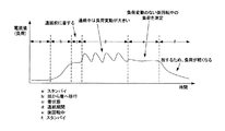
図7に定着器の負荷変動の様子を示す。区間aは、プリント動作を行わないスタンバイ状態なので、定着器は脱状態であるため、電流値、即ち負荷は軽い状態である。区間bは、プリント動作を行うため、定着器が脱状態から着状態へ移行するため、負荷が増大していく。区間cは、定着器の着状態で負荷は一定となる。区間dは、通紙状態であるため、紙の突入ショック等で負荷変動が大きく、電流値は一定とならない。区間eは、通紙終了後の後回転期間であり、この期間は定着器が着しており、かつ通紙していない負荷一定の期間である。区間fは、プリント動作が終了し、スタンバイに戻るため、定着器は着から脱へ移行し、負荷は軽くなる。 FIG. 7 shows the load fluctuation of the fixing device. Since section a is in a standby state in which no printing operation is performed, the fixing device is in a detached state, so that the current value, that is, the load is light. In the section b, since the printing operation is performed, the load is increased because the fixing device shifts from the detached state to the worn state. In section c, the load is constant when the fixing device is worn. Since the section d is in the paper passing state, the load fluctuation is large due to a paper rush shock or the like, and the current value is not constant. The section e is a post-rotation period after the end of paper passing, and this period is a constant load period when the fixing device is worn and the paper is not passed. In the section f, since the printing operation ends and returns to the standby state, the fixing device shifts from wearing to unloading, and the load is lightened.
定着器が着状態で正確な負荷測定を行うためには、負荷変動の大きい通紙時は適しておらず、非通紙時に行うことが好ましい。また、プリントシーケンスに影響を与えずに測定することも重要である。例えば、通紙前の着状態(区間c)などはFCOT(First Copy Out Time:コピー1枚目の排出時間)に影響を与える可能性があるため、測定期間としては好ましくない。したがって、本実施例では、負荷変動が少なく、かつプリントシーケンスに影響を与えない区間e、即ち後回転中に負荷測定を行うこととする。ただし、プリントシーケンスに影響を与えないことが明白であれば、通紙前の着状態(区間c)で測定しても構わない。 In order to perform accurate load measurement with the fixing device in a worn state, it is not suitable when a paper having a large load fluctuation is passed, and is preferably performed when a paper is not passed. It is also important to measure without affecting the print sequence. For example, since the wearing state (section c) before passing paper may affect FCOT (First Copy Out Time), it is not preferable as the measurement period. Therefore, in the present embodiment, load measurement is performed during the section e in which the load fluctuation is small and the print sequence is not affected, that is, during post-rotation. However, if it is clear that the print sequence is not affected, the measurement may be performed in the wearing state (section c) before passing the paper.
図8に時間経過による定着器の駆動負荷が変化する様子を示す。時間が経過することで負荷が増大していき、負荷がある値を超えると周辺のメカ機構にダメージを与えてしまうので、その値に達する直前に定着器を交換することがランニングコスト的にも望ましい。 FIG. 8 shows how the driving load of the fixing device changes with time. Over time, the load will increase, and if the load exceeds a certain value, the surrounding mechanical mechanism will be damaged, so replacing the fixing device immediately before reaching that value also reduces the running cost. desirable.
図9に本実施例における、寿命の判断を行うフローチャートを示す。ステップS201で電源ONされると、ステップS202でスタンバイ状態となる。ステップS203でプリント動作を開始すると、ステップS204で定着器を脱状態から着状態にする。ステップS205でプリントを行う、すなわち通紙状態である。ステップS206で後回転状態か否か判断する。後回転中であれば、ステップS207に進み、後回転中でなければ次のプリント(通紙)を行う(ステップS205)。後回転中であれば、ステップS207で定着器の負荷測定を行う。ステップS208で測定した負荷が閾値を超えていた場合はステップS209へ、超えていなかった場合はステップS210へ進む。ステップS209では、測定値が閾値を超えているので定着器が寿命に達していると判断し、ステップS211でプリントシーケンスを終了し、エラー表示を行う。ステップS210では、測定値が閾値を超えていないので定着器は寿命に達していないと判断し、ステップS212でプリントシーケンスを終了して、稼動を継続する。 FIG. 9 shows a flowchart for determining the life in this embodiment. When the power is turned on in step S201, a standby state is set in step S202. When the printing operation is started in step S203, the fixing device is changed from the detached state to the wearing state in step S204. In step S205, printing is performed, that is, the sheet is in a passing state. In step S206, it is determined whether or not the vehicle is in the post-rotation state. If the post-rotation is in progress, the process proceeds to step S207. If the post-rotation is not in progress, the next printing (paper passing) is performed (step S205). If post-rotation is in progress, the load on the fixing device is measured in step S207. If the load measured in step S208 exceeds the threshold, the process proceeds to step S209. If not, the process proceeds to step S210. In step S209, since the measured value exceeds the threshold value, it is determined that the fixing device has reached the end of life, and in step S211, the print sequence is terminated and an error display is performed. In step S210, since the measured value does not exceed the threshold value, it is determined that the fixing device has not reached the end of its life. In step S212, the print sequence is terminated and the operation is continued.
以上説明したように、後回転中の定着器の負荷測定を行うことで、正確な定着器の負荷測定が可能になり、高精度に寿命を判断することができるようになり、ランニングコストの削減や、製品の信頼性を向上させることが可能となる。 As described above, by measuring the load on the fuser during post-rotation, it is possible to accurately measure the load on the fuser, and to determine the life with high accuracy, thereby reducing running costs. In addition, the reliability of the product can be improved.
実施例2として、定着器の寿命を判断する従来の方法である所定の通紙枚数、所定の駆動積算時間も併用する方法を説明する。 As a second embodiment, a conventional method for determining the life of a fixing device, which uses a predetermined number of sheets to be passed and a predetermined drive integration time together, will be described.
測定した定着器の負荷とその時点の通紙枚数、あるいは駆動積算時間により、その後の動作を判断する。例えば、測定した定着器の負荷(電流値)がある範囲、仮に定着器寿命とされる値の90〜95%の範囲にあった場合を考える。通紙枚数が20万枚以下、かつ駆動積算時間が4000時間以下であれば、ユーザにワーニング、即ち“定着器の交換時期が近づいています”などのメッセージを通知する。同じ負荷(電流値)であっても、通紙枚数が20万枚以上、あるいは駆動積算時間が4000時間以上であれば、定着器の寿命に達していると判断して、エラー、即ち“定着器を交換してください”などのメッセージを通知する。ただし、測定した定着器の負荷(電流値)範囲、通紙枚数、駆動積算時間は、本実施例で挙げている範囲や枚数、時間である必要はない。 The subsequent operation is determined based on the measured load of the fixing device and the number of sheets passed at that time, or the drive integration time. For example, let us consider a case where the measured load (current value) of the fixing device is within a certain range, that is, within a range of 90 to 95% of the value regarded as the fixing device lifetime. If the number of sheets to be passed is 200,000 sheets or less and the cumulative driving time is 4000 hours or less, the user is notified of a warning, that is, a message such as “Fixer replacement time is approaching”. Even with the same load (current value), if the number of sheets to be passed is 200,000 sheets or more, or if the drive integration time is 4000 hours or more, it is determined that the life of the fixing device has been reached and an error, that is, “fixing” Please replace the device ”message. However, the measured load (current value) range of the fixing device, the number of sheets passed, and the drive integration time do not have to be the range, the number of sheets, and the time described in the present embodiment.
図10に、フローチャートを示す。 FIG. 10 shows a flowchart.
ステップS301で電源ONされると、ステップS302でスタンバイ状態となる。ステップS303でプリント動作を開始すると、ステップS304で定着器を脱状態から着状態にする。ステップS305でプリントを行う、すなわち通紙状態である。ステップS306で後回転状態か否か判断する。後回転中であれば、ステップS307に進み、後回転中でなければ次のプリント(通紙)を行う(ステップS305)。後回転中であれば、ステップS307で定着器の負荷測定を行う。ステップS308で測定した負荷がある範囲より小さければステップS309へ、小さくなければステップS310へ進む。ステップS309では、測定値がある範囲より小さいので定着器はまだ寿命に達していないと判断し、ステップS311でプリントシーケンスを終了して、稼動を継続する。ステップS310では、測定値がある範囲より大きければステップS312へ、大きくなければステップS313へ進む。ステップS312では、測定値がある範囲より大きいので定着器は寿命に達していると判断し、ステップS314でプリントシーケンスを終了して、エラー表示する。ステップS313は、ステップS308とステップS310から除外されている、即ち定着器の測定した負荷がある所定の範囲内にあるということである。よって、通紙枚数が所定枚数以下、かつ駆動積算時間が所定時間以下であればステップS315へ、そうでなければ、即ち通紙枚数が所定枚数を超えている、あるいは駆動積算時間が所定時間を超えているのでステップS312に進む。ステップS315では、定着器の負荷がある所定の範囲内であり、通紙枚数が所定枚数以下、かつ駆動積算時間が所定時間以下なので定着器の寿命に近いと判断し、ステップS316でプリントシーケンスを終了して、ワーニング表示する。 When the power is turned on in step S301, a standby state is set in step S302. When the printing operation is started in step S303, the fixing device is changed from the detached state to the wearing state in step S304. In step S305, printing is performed, that is, a sheet is being passed. In step S306, it is determined whether or not the vehicle is in the post-rotation state. If the post-rotation is in progress, the process proceeds to step S307. If the post-rotation is not in progress, the next printing (paper passing) is performed (step S305). If post-rotation is in progress, the load on the fixing device is measured in step S307. If the load measured in step S308 is smaller than a certain range, the process proceeds to step S309, and if not smaller, the process proceeds to step S310. In step S309, since the measured value is smaller than a certain range, it is determined that the fixing device has not reached the end of its life, and in step S311, the print sequence is terminated and the operation is continued. In step S310, if the measured value is larger than a certain range, the process proceeds to step S312 and if not larger, the process proceeds to step S313. In step S312, since the measured value is larger than a certain range, it is determined that the fixing unit has reached the end of its life. In step S314, the print sequence is terminated and an error is displayed. Step S313 is excluded from steps S308 and S310, that is, the measured load of the fixing device is within a predetermined range. Therefore, if the number of sheets to be passed is less than or equal to the predetermined number and the accumulated driving time is less than or equal to the predetermined time, the process proceeds to step S315. Since it exceeds, it progresses to step S312. In step S315, it is determined that the life of the fixing device is close because the load of the fixing device is within a predetermined range, the number of sheets to be passed is not more than a predetermined number, and the drive integration time is not more than a predetermined time. In step S316, the print sequence is determined. Exit and display a warning.
なお、定着ユニット40の通紙枚数を計測し記憶する手段としては、例えば、CPU104を用いる。このとき、計測した通紙枚数は、CPU104内部のレジスタに記憶させても、CPU104外部の不揮発性メモリ等に記憶させてもよい。同様に、定着ユニット40の駆動積算時間を計測し記憶する手段としても、例えば、CPU104を用いることができる。通紙枚数の場合と同様に、計測した駆動積算時間は、CPU104内部のレジスタに記憶させても、CPU104外部の不揮発性メモリ等に記憶させてもよい。
For example, the
以上説明したように、定着器の負荷測定を行い、その値と通紙枚数あるいは積算稼働時間の両者から定着器の寿命を判断することで、画像形成装置の使用状況にあわせた寿命判断を行うことができるようになる。 As described above, the load of the fixing device is measured, and the life of the fixing device is determined from both the value, the number of sheets to be passed, and the accumulated operation time, thereby determining the life according to the usage state of the image forming apparatus. Will be able to.
1R 画像読取部
1P 画像出力部
10 画像形成部
11 感光体ドラム
12 一次帯電器
20 給紙ユニット
30 中間転写ユニット
40 定着ユニット(画像定着装置に相当)
41a 上ベルトユニット(回転体に相当)
41b 下ベルトユニット(加圧回転体に相当)
42a 上定着ベルト
42b 下定着ベルト
43a 上駆動ローラ
43b 下駆動ローラ
44a 上従動ローラ
44b 下従動ローラ
45a 上加圧パッド
45b 下加圧パッド
46 着脱モータ
47 定着駆動モータ(回転駆動手段に相当)
48 定着入口センサ
49 内排紙センサ
103 トルク検知装置(駆動負荷測定手段に相当)
104 CPU(交換時期判断手段に相当)(画像定着装置の通紙枚数を計測し記憶する手段および画像定着装置の駆動積算時間を計測し記憶する手段に相当)
P 転写材(記録材に相当)
1R
41a Upper belt unit (equivalent to rotating body)
41b Lower belt unit (equivalent to a pressure rotating body)
42a
48
104 CPU (corresponding to replacement time determining means) (corresponding to means for measuring and storing the number of sheets passing through the image fixing device and means for measuring and storing the driving integration time of the image fixing device)
P transfer material (equivalent to recording material)
Claims (3)
前記回転体と前記加圧回転体により前記ニップ部が形成され前記駆動負荷が変動しない非通紙期間に前記駆動負荷測定手段により該駆動負荷を測定し、測定した該駆動負荷の値が第一の所定値より大きい場合には前記画像定着装置の交換時期であると判断する交換時期判断手段と、
前記画像定着装置の通紙枚数を計測する第一の計測手段と、
前記画像定着装置の駆動積算時間を計測する第二の計測手段と、
を備え、
前記交換時期判断手段は、前記駆動負荷測定手段により測定した駆動負荷の値が前記第一の所定値以下で且つ第二の所定値以上である場合に、前記第一の計測手段により計測された通紙枚数が所定枚数より多い又は前記第二の計測手段により計測された駆動積算時間が所定時間より長い場合には前記画像定着装置の交換時期であると判断することを特徴とする画像形成装置。 A rotating body for fixing a recording material on which a toner image is formed, a pressure rotating body that presses against the rotating body to form a nip portion, and a rotational drive that rotationally drives the rotating body and the pressure rotating body. And an image fixing device for fixing the image on the recording material by sandwiching and transporting the recording material at the nip portion. In the device
The driving load is measured by the driving load measuring means during a non-sheet passing period in which the nip portion is formed by the rotating body and the pressure rotating body and the driving load does not vary, and the measured driving load value is the first value. and replacement time determining means for determining that if greater than the predetermined value is time to replace the image fixing device,
First measuring means for measuring the number of sheets of the image fixing device;
A second measuring means for measuring the driving integration time of the image fixing device;
Equipped with a,
The replacement time determining means is measured by the first measuring means when the value of the driving load measured by the driving load measuring means is not more than the first predetermined value and not less than a second predetermined value. image forming number of fed sheets is characterized that you determine cumulative drive time measured by the more or the second measurement unit from the predetermined number a is longer than the predetermined time is time to replace the image fixing device apparatus.
Priority Applications (1)
| Application Number | Priority Date | Filing Date | Title |
|---|---|---|---|
| JP2006136357A JP4921035B2 (en) | 2006-05-16 | 2006-05-16 | Image forming apparatus |
Applications Claiming Priority (1)
| Application Number | Priority Date | Filing Date | Title |
|---|---|---|---|
| JP2006136357A JP4921035B2 (en) | 2006-05-16 | 2006-05-16 | Image forming apparatus |
Publications (3)
| Publication Number | Publication Date |
|---|---|
| JP2007309980A JP2007309980A (en) | 2007-11-29 |
| JP2007309980A5 JP2007309980A5 (en) | 2009-01-29 |
| JP4921035B2 true JP4921035B2 (en) | 2012-04-18 |
Family
ID=38842927
Family Applications (1)
| Application Number | Title | Priority Date | Filing Date |
|---|---|---|---|
| JP2006136357A Expired - Fee Related JP4921035B2 (en) | 2006-05-16 | 2006-05-16 | Image forming apparatus |
Country Status (1)
| Country | Link |
|---|---|
| JP (1) | JP4921035B2 (en) |
Families Citing this family (14)
| Publication number | Priority date | Publication date | Assignee | Title |
|---|---|---|---|---|
| JP5552732B2 (en) * | 2008-03-31 | 2014-07-16 | 株式会社リコー | Fixing apparatus and image forming apparatus |
| JP5429690B2 (en) * | 2009-09-14 | 2014-02-26 | 株式会社リコー | Image forming apparatus and power consumption notification method |
| JP5561036B2 (en) | 2009-10-15 | 2014-07-30 | 株式会社リコー | Failure determination device, fixing device, image forming apparatus, failure determination system |
| JP5350176B2 (en) * | 2009-10-22 | 2013-11-27 | キヤノン株式会社 | Fixing device |
| JP5777289B2 (en) * | 2010-03-29 | 2015-09-09 | キヤノン株式会社 | Image heating device |
| JP5696773B2 (en) * | 2013-12-11 | 2015-04-08 | 株式会社リコー | Image forming apparatus |
| JP6558913B2 (en) | 2014-03-04 | 2019-08-14 | キヤノン株式会社 | Image forming apparatus |
| JP2018159852A (en) * | 2017-03-23 | 2018-10-11 | 富士ゼロックス株式会社 | Fixing device and image forming apparatus |
| JP6929693B2 (en) * | 2017-05-01 | 2021-09-01 | キヤノン株式会社 | Image forming device |
| JP2019152790A (en) * | 2018-03-05 | 2019-09-12 | コニカミノルタ株式会社 | Image forming apparatus |
| JP2019159093A (en) | 2018-03-13 | 2019-09-19 | コニカミノルタ株式会社 | Image forming apparatus and control program of image forming apparatus |
| JP7294002B2 (en) * | 2019-09-04 | 2023-06-20 | コニカミノルタ株式会社 | Image forming apparatus, information processing system, and information processing method |
| JP7294001B2 (en) * | 2019-09-04 | 2023-06-20 | コニカミノルタ株式会社 | Image forming apparatus, information processing system, and information processing method |
| JP7392416B2 (en) * | 2019-11-21 | 2023-12-06 | コニカミノルタ株式会社 | Image forming device |
Family Cites Families (4)
| Publication number | Priority date | Publication date | Assignee | Title |
|---|---|---|---|---|
| JP2001005353A (en) * | 1999-06-25 | 2001-01-12 | Fuji Xerox Co Ltd | Fixing device |
| JP2002369588A (en) * | 2001-06-04 | 2002-12-20 | Fuji Xerox Co Ltd | Imaging apparatus |
| JP2005300986A (en) * | 2004-04-13 | 2005-10-27 | Canon Inc | Fixing apparatus |
| JP2005326719A (en) * | 2004-05-17 | 2005-11-24 | Canon Inc | Image forming apparatus |
-
2006
- 2006-05-16 JP JP2006136357A patent/JP4921035B2/en not_active Expired - Fee Related
Also Published As
| Publication number | Publication date |
|---|---|
| JP2007309980A (en) | 2007-11-29 |
Similar Documents
| Publication | Publication Date | Title |
|---|---|---|
| JP4921035B2 (en) | Image forming apparatus | |
| US7398027B2 (en) | Image forming apparatus with conveyance speed control based in part on loop detection | |
| JP4594199B2 (en) | Image forming apparatus and image forming apparatus control method | |
| JP4632820B2 (en) | Image forming apparatus | |
| JP5022629B2 (en) | Fixing apparatus and image forming apparatus | |
| US7949272B2 (en) | Image forming apparatus with control of a contact position of fixing and pressure rollers | |
| JP5171217B2 (en) | Image forming apparatus | |
| JP2007328175A (en) | Image forming apparatus | |
| JP4564769B2 (en) | Image forming apparatus | |
| JP5832194B2 (en) | Image forming apparatus | |
| JP5824948B2 (en) | Fixing apparatus and image forming apparatus | |
| JP4561959B2 (en) | Image forming apparatus | |
| JP2007309982A (en) | Image fixing device | |
| JP2005202110A (en) | Image forming apparatus | |
| JP5793898B2 (en) | Image forming apparatus | |
| JP4340481B2 (en) | Image forming apparatus | |
| JP2022020930A (en) | Image forming apparatus | |
| JP5232612B2 (en) | Image forming apparatus | |
| JP2007309988A (en) | Fixing device | |
| US11892791B2 (en) | Image forming apparatus | |
| JP2003248359A (en) | Image forming apparatus | |
| JP2011017879A (en) | Image forming apparatus | |
| JP2006267549A (en) | Image forming apparatus | |
| JP2008145538A (en) | Image forming apparatus | |
| JP2007108562A (en) | Image forming apparatus |
Legal Events
| Date | Code | Title | Description |
|---|---|---|---|
| A521 | Written amendment |
Free format text: JAPANESE INTERMEDIATE CODE: A523 Effective date: 20081204 |
|
| A621 | Written request for application examination |
Free format text: JAPANESE INTERMEDIATE CODE: A621 Effective date: 20081204 |
|
| A977 | Report on retrieval |
Free format text: JAPANESE INTERMEDIATE CODE: A971007 Effective date: 20110401 |
|
| A131 | Notification of reasons for refusal |
Free format text: JAPANESE INTERMEDIATE CODE: A131 Effective date: 20110531 |
|
| A521 | Written amendment |
Free format text: JAPANESE INTERMEDIATE CODE: A523 Effective date: 20110706 |
|
| TRDD | Decision of grant or rejection written | ||
| A01 | Written decision to grant a patent or to grant a registration (utility model) |
Free format text: JAPANESE INTERMEDIATE CODE: A01 Effective date: 20120124 |
|
| A01 | Written decision to grant a patent or to grant a registration (utility model) |
Free format text: JAPANESE INTERMEDIATE CODE: A01 |
|
| A61 | First payment of annual fees (during grant procedure) |
Free format text: JAPANESE INTERMEDIATE CODE: A61 Effective date: 20120202 |
|
| FPAY | Renewal fee payment (event date is renewal date of database) |
Free format text: PAYMENT UNTIL: 20150210 Year of fee payment: 3 |
|
| LAPS | Cancellation because of no payment of annual fees |