JP4916552B2 - Recessed ceiling air conditioner - Google Patents
Recessed ceiling air conditioner Download PDFInfo
- Publication number
- JP4916552B2 JP4916552B2 JP2009531270A JP2009531270A JP4916552B2 JP 4916552 B2 JP4916552 B2 JP 4916552B2 JP 2009531270 A JP2009531270 A JP 2009531270A JP 2009531270 A JP2009531270 A JP 2009531270A JP 4916552 B2 JP4916552 B2 JP 4916552B2
- Authority
- JP
- Japan
- Prior art keywords
- panel
- ceiling
- air conditioner
- screw
- decorative panel
- Prior art date
- Legal status (The legal status is an assumption and is not a legal conclusion. Google has not performed a legal analysis and makes no representation as to the accuracy of the status listed.)
- Active
Links
Images


Classifications
-
- F—MECHANICAL ENGINEERING; LIGHTING; HEATING; WEAPONS; BLASTING
- F24—HEATING; RANGES; VENTILATING
- F24F—AIR-CONDITIONING; AIR-HUMIDIFICATION; VENTILATION; USE OF AIR CURRENTS FOR SCREENING
- F24F13/00—Details common to, or for air-conditioning, air-humidification, ventilation or use of air currents for screening
- F24F13/08—Air-flow control members, e.g. louvres, grilles, flaps or guide plates
- F24F13/082—Grilles, registers or guards
- F24F13/084—Grilles, registers or guards with mounting arrangements, e.g. snap fasteners for mounting to the wall or duct
-
- F—MECHANICAL ENGINEERING; LIGHTING; HEATING; WEAPONS; BLASTING
- F16—ENGINEERING ELEMENTS AND UNITS; GENERAL MEASURES FOR PRODUCING AND MAINTAINING EFFECTIVE FUNCTIONING OF MACHINES OR INSTALLATIONS; THERMAL INSULATION IN GENERAL
- F16B—DEVICES FOR FASTENING OR SECURING CONSTRUCTIONAL ELEMENTS OR MACHINE PARTS TOGETHER, e.g. NAILS, BOLTS, CIRCLIPS, CLAMPS, CLIPS OR WEDGES; JOINTS OR JOINTING
- F16B35/00—Screw-bolts; Stay-bolts; Screw-threaded studs; Screws; Set screws
- F16B35/04—Screw-bolts; Stay-bolts; Screw-threaded studs; Screws; Set screws with specially-shaped head or shaft in order to fix the bolt on or in an object
- F16B35/041—Specially-shaped shafts
-
- F—MECHANICAL ENGINEERING; LIGHTING; HEATING; WEAPONS; BLASTING
- F24—HEATING; RANGES; VENTILATING
- F24F—AIR-CONDITIONING; AIR-HUMIDIFICATION; VENTILATION; USE OF AIR CURRENTS FOR SCREENING
- F24F1/00—Room units for air-conditioning, e.g. separate or self-contained units or units receiving primary air from a central station
- F24F1/0007—Indoor units, e.g. fan coil units
- F24F1/0043—Indoor units, e.g. fan coil units characterised by mounting arrangements
- F24F1/0047—Indoor units, e.g. fan coil units characterised by mounting arrangements mounted in the ceiling or at the ceiling
-
- F—MECHANICAL ENGINEERING; LIGHTING; HEATING; WEAPONS; BLASTING
- F24—HEATING; RANGES; VENTILATING
- F24F—AIR-CONDITIONING; AIR-HUMIDIFICATION; VENTILATION; USE OF AIR CURRENTS FOR SCREENING
- F24F13/00—Details common to, or for air-conditioning, air-humidification, ventilation or use of air currents for screening
- F24F13/20—Casings or covers
-
- F—MECHANICAL ENGINEERING; LIGHTING; HEATING; WEAPONS; BLASTING
- F16—ENGINEERING ELEMENTS AND UNITS; GENERAL MEASURES FOR PRODUCING AND MAINTAINING EFFECTIVE FUNCTIONING OF MACHINES OR INSTALLATIONS; THERMAL INSULATION IN GENERAL
- F16B—DEVICES FOR FASTENING OR SECURING CONSTRUCTIONAL ELEMENTS OR MACHINE PARTS TOGETHER, e.g. NAILS, BOLTS, CIRCLIPS, CLAMPS, CLIPS OR WEDGES; JOINTS OR JOINTING
- F16B41/00—Measures against loss of bolts, nuts, or pins; Measures against unauthorised operation of bolts, nuts or pins
- F16B41/002—Measures against loss of bolts, nuts or pins
-
- F—MECHANICAL ENGINEERING; LIGHTING; HEATING; WEAPONS; BLASTING
- F16—ENGINEERING ELEMENTS AND UNITS; GENERAL MEASURES FOR PRODUCING AND MAINTAINING EFFECTIVE FUNCTIONING OF MACHINES OR INSTALLATIONS; THERMAL INSULATION IN GENERAL
- F16B—DEVICES FOR FASTENING OR SECURING CONSTRUCTIONAL ELEMENTS OR MACHINE PARTS TOGETHER, e.g. NAILS, BOLTS, CIRCLIPS, CLAMPS, CLIPS OR WEDGES; JOINTS OR JOINTING
- F16B5/00—Joining sheets or plates, e.g. panels, to one another or to strips or bars parallel to them
- F16B5/02—Joining sheets or plates, e.g. panels, to one another or to strips or bars parallel to them by means of fastening members using screw-thread
- F16B5/0275—Joining sheets or plates, e.g. panels, to one another or to strips or bars parallel to them by means of fastening members using screw-thread the screw-threaded element having at least two axially separated threaded portions
Landscapes
- Engineering & Computer Science (AREA)
- General Engineering & Computer Science (AREA)
- Mechanical Engineering (AREA)
- Chemical & Material Sciences (AREA)
- Combustion & Propulsion (AREA)
- Air Filters, Heat-Exchange Apparatuses, And Housings Of Air-Conditioning Units (AREA)
Abstract
Description
本発明は天井埋込形空気調和機に係り、特に化粧パネルの取付構造を改良した天井埋込形空気調和機に関する。 The present invention relates to a ceiling-embedded air conditioner, and more particularly to a ceiling-embedded air conditioner with an improved decorative panel mounting structure.
一般に天井埋込形空気調和機は、天井に埋め込まれる室内ユニット本体の下面を化粧パネルで覆う構造になっている。 Generally, a ceiling-embedded air conditioner has a structure in which a lower surface of an indoor unit body embedded in a ceiling is covered with a decorative panel.
従来の化粧パネルの室内ユニット本体への取付構造は、化粧パネルを仮掛けした後に、付属のねじを用いて室内ユニット本体に螺着するか、化粧パネル側に固定ねじと仮掛けが一体となった取り付けねじ部材を用いて、これを室内ユニットに引掛けて螺着する構造であった(例えば、特許文献1:特開2006−17342号公報)。 The conventional mounting structure of the decorative panel to the indoor unit main body is that the decorative panel is temporarily hung and then screwed to the indoor unit main body using the attached screws, or the fixing screw and temporary hook are integrated on the decorative panel side. The mounting screw member is used to be hooked on the indoor unit and screwed (for example, Japanese Patent Application Laid-Open No. 2006-17342).
しかし、特許文献1に記載にように、付属のねじで固定する方法では、ねじが落下したり紛失してしまう、ねじを下孔に合わせて締め込むため、作業性に劣る問題があった。また、化粧パネル側の固定ねじと仮掛けが一体となった取り付けねじ部材を本体に引掛けて締め付ける方法では、ねじの落下や紛失の心配はないが、仮掛け作業がやりにくい問題があった。 However, as described in Patent Document 1, in the method of fixing with the attached screw, the screw falls or is lost, and the screw is tightened in accordance with the prepared hole. In addition, with the method of hooking the mounting screw member with the decorative panel side fixing screw and temporary hook on the main body and tightening, there is no risk of dropping or losing the screw, but there is a problem that temporary hanging work is difficult to do. .
発明の開示
本発明は上述した事情を考慮してなされたもので、容易に化粧パネルを室内ユニット本体に取り付けることができる天井埋込形空気調和機を提供することを目的とする。DISCLOSURE OF THE INVENTION The present invention has been made in view of the above-described circumstances, and an object thereof is to provide a ceiling-embedded air conditioner in which a decorative panel can be easily attached to an indoor unit body.
上述した目的を達成するため、本発明に係る天井埋込形空気調和機は、天井に埋め込まれる室内ユニット本体と、この室内ユニット本体の下面を覆う化粧パネルで構成される天井埋込形空気調和機において、前記室内ユニット本体に前記化粧パネルを固定するパネル固定ねじは、予め室内ユニット本体側に取り付けられかつ、中間部にねじ山がない細径部を有することを特徴とする。 In order to achieve the above-described object, a ceiling-embedded air conditioner according to the present invention includes an indoor unit body embedded in the ceiling and a ceiling-embedded air conditioner that includes a decorative panel that covers the lower surface of the indoor unit body. In the machine, the panel fixing screw for fixing the decorative panel to the indoor unit main body has a small-diameter portion that is attached in advance to the indoor unit main body side and has no thread at the intermediate portion.
また、好適な実施例においては、前記化粧パネルを固定するパネル固定部材を前記化粧パネルに進退自在に設け、前記パネル固定部材は前記パネル固定ねじに係合するねじ係合溝を備え、前記パネル固定部材の前進状態で、前記パネル固定ねじに係合される。 In a preferred embodiment, a panel fixing member for fixing the decorative panel is provided in the decorative panel so as to be able to advance and retract. The panel fixing member includes a screw engaging groove for engaging with the panel fixing screw. When the fixing member is in the advanced state, it is engaged with the panel fixing screw.
また、前記化粧パネルにフック、前記室内ユニット本体に前記フックが係合するフック係合部を設け、前記フックを前記フック係合部に係合させて、化粧パネルを前記室内ユニット本体に仮掛けしても良い。 In addition, the decorative panel is provided with a hook, and the indoor unit main body is provided with a hook engaging portion that engages with the hook. The hook is engaged with the hook engaging portion, and the decorative panel is temporarily hung on the indoor unit main body. You may do it.
本発明に係る天井埋込形空気調和機によれば、容易に化粧パネルを室内ユニット本体に取り付けることができる天井埋込形空気調和機を提供することができる。 The ceiling-embedded air conditioner according to the present invention can provide a ceiling-embedded air conditioner in which a decorative panel can be easily attached to an indoor unit body.
本発明の一実施形態に係る天井埋込形空気調和機について図面を参照して説明する。 A ceiling-embedded air conditioner according to an embodiment of the present invention will be described with reference to the drawings.
図1は本発明の一実施形態に係る天井埋込形空気調和機の斜視図であり、図2は本天井埋込形空気調和機の室内ユニット本体の斜視図である。 FIG. 1 is a perspective view of a ceiling-embedded air conditioner according to an embodiment of the present invention, and FIG. 2 is a perspective view of an indoor unit body of the ceiling-embedded air conditioner.
図1および図2に示すように、本発明の一実施形態に係る天井埋込形空気調和機1は、天井に埋め込まれる室内ユニット本体2と、この室内ユニット本体2の下面を覆う化粧パネル3で構成される。
As shown in FIGS. 1 and 2, a ceiling-embedded air conditioner 1 according to an embodiment of the present invention includes an
室内ユニット本体2は筐体4を備え、この筐体4には室内熱交換器(図示せず)、室内送風機5などを収容する。
The indoor unit
筐体4は同様の4組の吊り下げ手段6によって天井基材(図示せず)に吊り下げて取り付けられる。 The casing 4 is attached to a ceiling base material (not shown) by four similar sets of suspension means 6.
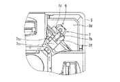
図3に拡大して示すように、各々の吊り下げ手段6は天井基材に取り付けた吊りボルト6aと、筐体4の一側壁4aに取り付けられる吊り金具6bと、この吊り金具6bを上下から挟み、吊りボルト6aが貫通し、図示しない上側ワッシャ、下側ワッシャ6cと、吊りボルト6aに螺合し、上下から吊り金具6b、上側ナット、下側ナット6dからなる。
As shown in FIG. 3 in an enlarged manner, each suspension means 6 includes a
一方、化粧パネル3は中央に着脱自在に取り付けられる吸込グリル3aを有する空気吸込口3b、4周辺に空気吹出口3cおよび4隅に作業開口3dを塞ぐ化粧板3eを備え、室内ユニット本体2の下面すなわち筐体4の開口部4bを塞ぐように、取付手段7によって筐体4に取り付けられる。
On the other hand, the
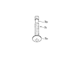
取付手段7は、室内ユニット本体2例えば筐体4の開口部4bに固着され、ネジ孔7a1を備えた取付片7aと、ネジ孔7a1に螺合するパネル固定ねじ7bと、このパネル固定ねじ7bの頭部7b1が貫通しパネル固定部3pに設けるねじ貫通孔3p1と、化粧パネル3に進退自在に取り付けられるパネル固定部材7cからなる。Attachment means 7 is secured to the
図4に示すように、パネル固定ねじ7bは先端部近傍に中間部すなわち頭部7b1と先端間にねじ山がない細径部7b2を設けてあり、細径部7b2と頭部7b1間で、ネジ孔7a1と螺合状態にあるパネル固定ねじ7bを、反時計回りに回転させると、パネル固定ねじ7bはネジ溝に沿って降下するが、細径部7b2はネジ孔7a1に達すると螺合が解除され、それ以上の降下はなく、パネル固定ねじ7bの落下が防止される。As shown in FIG. 4,
図3および図5はパネル固定部材7cの後退(待機)状態を示し、図6および図7はパネル固定部材7cの前進(係合)状態を示す。例えば、図5に示すように、パネル固定部材7cは、長方形板状をなし、先端にY字形状のねじ係合溝7c1と中央部近傍に案内溝7c2が設けられ、案内溝7c2を貫通する固定ねじ3fによって、化粧パネル3に進退自在に取り付けられる。3 and 5 show the retracted (standby) state of the
さらに、図3および図5に示すように、パネル固定部材7cは後退状態から、化粧パネル3の隅部に設けるパネル固定部3pの方向に前進させ、図6および図7に示すように、ねじ係合溝7c1がパネル固定部3pに設けるねじ貫通孔3p1を貫通しているパネル固定ねじ7bに係合し、パネル固定ねじ7bで締め付けられる。これにより、化粧パネル3は筐体4に取り付けられ、パネル固定部材7cは化粧パネル3の位置決めおよび座金の機能をはたす。Further, as shown in FIGS. 3 and 5, the
また、図8および図9に示すように、化粧パネル3の空気吸込口3bの対向する側部には、仮掛け用のフック3g、3gが設けられ、一方、筐体4の対向する内壁下部には、略対向し、フック3g、3gに対応する位置に2個のフック係合部4c、4cが設けられる。
Further, as shown in FIGS. 8 and 9,
図9および図10に示すように、フック3g、3gをフック係合部4c、4cに係合することで、化粧パネル3は筐体4に仮掛けする。
As shown in FIGS. 9 and 10, the
次に、取付手段7を用いた化粧パネル3の筐体4への取り付けについて説明する。
Next, attachment of the
図2に示すように、予め、取付片7aにパネル固定ねじ7bが取り付けられた筐体4を吊り下げ手段6を用いて天井基材に吊り下げる。
As shown in FIG. 2, the casing 4 in which the
図8に示すように、予め吸込グリル3aおよび化粧板3eを外した状態で、空気吸込口3bおよび作業開口3dを開口しておく。
As shown in FIG. 8, the
図9および図10に示すように、フック3g、3gをフック係合部4c、4cに係合することで、化粧パネル3は筐体4に仮掛けする。
As shown in FIGS. 9 and 10, the
図4および図5に示すように、化粧パネル3が筐体4に仮掛けされた状態では、パネル固定部材7cは後退状態にある。この状態でパネル固定ねじ7bはパネル固定部3pに設けるねじ貫通孔3p1を貫通し、ねじ頭部近傍がねじ貫通孔3p1外に露出する。As shown in FIGS. 4 and 5, the
図6および図7に示すように、パネル固定部材7cを前進させて、パネル固定部3pのねじ貫通孔3p1を貫通するパネル固定ねじ7bに係合させた後、固定ねじ3fによって、パネル固定部材7cの位置を固定し、さらに、パネル固定ねじ7bを締め付ける。パネル固定部材7cは、パネル固定部3pとパネル固定ねじ7bの頭部6bで狭持される。As shown in FIGS. 6 and 7, to advance the
図1に示すように、吸込グリル3aおよび化粧板3eを取り付けて、空気吸込口3bおよび作業開口3dを塞ぐ。
As shown in FIG. 1, the
このような手順により、化粧パネル3の筐体4への取り付けは完了する。
By such a procedure, the attachment of the
上記化粧パネルの取付過程において、パネル固定ねじが筐体に取り付けられているため、パネル固定ねじを紛失する心配がない。また、パネル固定ねじの締め付け時、パネル固定ねじとネジ孔を合わせる必要がなく、作業性がよい。 In the process of attaching the decorative panel, since the panel fixing screw is attached to the housing, there is no fear of losing the panel fixing screw. Further, when the panel fixing screw is tightened, it is not necessary to match the panel fixing screw and the screw hole, and the workability is good.
さらに、パネル固定ねじの頭部をパネル固定部のねじ貫通孔に貫通した後、パネル固定部材を前進させる単純な動作で化粧パネルの位置が決まり、パネル固定ねじを締め付けるだけで、正しい位置に取り付けが可能であり、作業性がよい。 Furthermore, after passing the head of the panel fixing screw through the screw through hole of the panel fixing part, the position of the decorative panel is determined by a simple operation of moving the panel fixing member forward, and it is attached to the correct position simply by tightening the panel fixing screw. Is possible and workability is good.
また、パネル固定部材をパネル固定ねじに係合し、パネル固定部とパネル固定ねじの頭部で狭持するので、化粧パネルの位置決めが容易になり、パネル固定部材は座金の機能をはたす。 Further, since the panel fixing member is engaged with the panel fixing screw and held between the panel fixing portion and the head of the panel fixing screw, the decorative panel can be easily positioned, and the panel fixing member functions as a washer.
さらに、フックとフック係合部を用いて、化粧パネルを筐体に仮掛けし、パネル固定部材とパネル固定ねじで化粧パネルの取り付けを行うので、取り付け作業性が向上する。 Furthermore, since the decorative panel is temporarily hung on the housing using the hook and the hook engaging portion, and the decorative panel is attached by the panel fixing member and the panel fixing screw, the attachment workability is improved.
また、メンテナンス等で化粧パネルを外す場合、パネル固定ねじを緩めすぎても、筐体からパネル固定ねじが外れ落ちてしまうことがなく、作業性がよい。 In addition, when removing the decorative panel for maintenance or the like, even if the panel fixing screw is loosened too much, the panel fixing screw does not come off from the housing and workability is good.
Claims (3)
Priority Applications (1)
| Application Number | Priority Date | Filing Date | Title |
|---|---|---|---|
| JP2009531270A JP4916552B2 (en) | 2007-09-07 | 2008-09-04 | Recessed ceiling air conditioner |
Applications Claiming Priority (4)
| Application Number | Priority Date | Filing Date | Title |
|---|---|---|---|
| JP2007233132 | 2007-09-07 | ||
| JP2007233132 | 2007-09-07 | ||
| JP2009531270A JP4916552B2 (en) | 2007-09-07 | 2008-09-04 | Recessed ceiling air conditioner |
| PCT/JP2008/065961 WO2009031609A1 (en) | 2007-09-07 | 2008-09-04 | Ceiling-buried type air conditioner |
Publications (2)
| Publication Number | Publication Date |
|---|---|
| JPWO2009031609A1 JPWO2009031609A1 (en) | 2010-12-16 |
| JP4916552B2 true JP4916552B2 (en) | 2012-04-11 |
Family
ID=40428922
Family Applications (1)
| Application Number | Title | Priority Date | Filing Date |
|---|---|---|---|
| JP2009531270A Active JP4916552B2 (en) | 2007-09-07 | 2008-09-04 | Recessed ceiling air conditioner |
Country Status (7)
| Country | Link |
|---|---|
| US (1) | US8636566B2 (en) |
| EP (1) | EP2192357B1 (en) |
| JP (1) | JP4916552B2 (en) |
| CN (1) | CN101796349B (en) |
| BR (1) | BRPI0816485B1 (en) |
| RU (1) | RU2443945C2 (en) |
| WO (1) | WO2009031609A1 (en) |
Families Citing this family (13)
| Publication number | Priority date | Publication date | Assignee | Title |
|---|---|---|---|---|
| JP5805186B2 (en) | 2011-06-09 | 2015-11-04 | 三菱電機株式会社 | Air conditioner indoor unit |
| CN102538166A (en) * | 2012-02-07 | 2012-07-04 | 乐金电子(天津)电器有限公司 | Front panel structure for embedded air conditioner indoor machine |
| JP5877173B2 (en) * | 2013-04-04 | 2016-03-02 | 古河電気工業株式会社 | Fastener and gripping device using the same |
| JP5811134B2 (en) * | 2013-04-30 | 2015-11-11 | ダイキン工業株式会社 | Air conditioner indoor unit |
| KR101706812B1 (en) | 2013-10-02 | 2017-02-14 | 엘지전자 주식회사 | Indoor unit for cassette type air conditoiner |
| KR101702169B1 (en) | 2013-10-02 | 2017-02-02 | 엘지전자 주식회사 | Indoor unit for cassette type air conditoiner |
| KR20150043573A (en) | 2013-10-11 | 2015-04-23 | 엘지전자 주식회사 | Indoor unit for cassette type air conditoiner |
| KR101662377B1 (en) | 2014-01-27 | 2016-10-04 | 엘지전자 주식회사 | Indoor unit of air conditoiner |
| JP6188618B2 (en) * | 2014-03-31 | 2017-08-30 | 三菱電機株式会社 | Air conditioner packing apparatus and air conditioner |
| CN106016471A (en) * | 2016-07-13 | 2016-10-12 | 海信(山东)空调有限公司 | Embedded air conditioner |
| CN106642312B (en) * | 2016-10-09 | 2019-05-24 | 青岛海信日立空调系统有限公司 | An embedded air conditioner and its installation process |
| WO2018154765A1 (en) * | 2017-02-27 | 2018-08-30 | 東芝キヤリア株式会社 | Ceiling panel and air conditioner |
| EP3734180B1 (en) * | 2019-03-03 | 2021-08-18 | GD Midea Air-Conditioning Equipment Co., Ltd. | Fresh air panel assembly, air conditioner indoor unit and air conditioner |
Citations (5)
| Publication number | Priority date | Publication date | Assignee | Title |
|---|---|---|---|---|
| JPH036231A (en) * | 1989-06-02 | 1991-01-11 | Mitsui Petrochem Ind Ltd | New polymer and its use |
| JPH10205804A (en) * | 1997-01-16 | 1998-08-04 | Sanyo Electric Co Ltd | Air conditioner |
| JPH10292928A (en) * | 1997-04-18 | 1998-11-04 | Fujitsu General Ltd | Ceiling-mounted air conditioner |
| JP2006132893A (en) * | 2004-11-09 | 2006-05-25 | Matsushita Electric Ind Co Ltd | Recessed ceiling air conditioner |
| JP2007010222A (en) * | 2005-06-30 | 2007-01-18 | Matsushita Electric Ind Co Ltd | Embedded ceiling air conditioner |
Family Cites Families (37)
| Publication number | Priority date | Publication date | Assignee | Title |
|---|---|---|---|---|
| SU1723379A1 (en) * | 1968-07-02 | 1992-03-30 | В.В.Вахмистров | Separable screw joint |
| JPS60191814A (en) | 1984-03-12 | 1985-09-30 | Nissan Motor Co Ltd | Weather strip for automobile |
| KR860000661B1 (en) | 1984-05-17 | 1986-05-29 | 한국과학기술원 | Process for preparing catalysts for disproportionating chlorosilane |
| US4877364A (en) * | 1985-07-24 | 1989-10-31 | General Datacomm. Inc. | Captive screw and assembly |
| JPS6454153A (en) * | 1987-08-24 | 1989-03-01 | Matsushita Seiko Kk | Ventilating fan for duct |
| US4786119A (en) * | 1987-12-23 | 1988-11-22 | Metalworks, Inc. | Locking clip for securing a bolt holding panel members together |
| JPH02133739A (en) * | 1988-11-11 | 1990-05-22 | Sanyo Electric Co Ltd | Device for ventilating hole recessed in ceiling |
| JPH02176337A (en) * | 1988-12-27 | 1990-07-09 | Matsushita Seiko Co Ltd | Ventilating fan for duct |
| JPH036231U (en) * | 1989-06-06 | 1991-01-22 | ||
| JPH0533980A (en) * | 1991-07-31 | 1993-02-09 | Matsushita Seiko Co Ltd | Ventilator for duct |
| JPH05256489A (en) * | 1992-03-13 | 1993-10-05 | Toshiba Corp | Ventilator for ceiling |
| JP3133533B2 (en) * | 1992-10-15 | 2001-02-13 | 東芝キヤリア株式会社 | Ceiling ventilation fan |
| JPH06300341A (en) * | 1993-04-14 | 1994-10-28 | Toshiba Corp | Ventilating fan for ceiling |
| US5425674A (en) * | 1993-10-26 | 1995-06-20 | Stach; William R. | Cover for swamp cooler and methods |
| JPH0886504A (en) | 1994-09-16 | 1996-04-02 | Hitachi Air Conditioning & Refrig Co Ltd | Air conditioner |
| JP3240854B2 (en) | 1994-09-26 | 2001-12-25 | 三菱電機株式会社 | Air conditioner outlet |
| JP3019743B2 (en) | 1995-04-11 | 2000-03-13 | ダイキン工業株式会社 | Air conditioner |
| JP2943751B2 (en) | 1997-01-20 | 1999-08-30 | ダイキン工業株式会社 | Air conditioner |
| JPH11325035A (en) * | 1998-05-18 | 1999-11-26 | Terada Denki Seisakusho:Kk | Fall preventing screw |
| KR100402195B1 (en) | 2000-01-28 | 2003-10-22 | 도시바 캐리어 가부시키 가이샤 | Cassette type air conditioner for mounting in the ceiling |
| JP3624813B2 (en) | 2000-09-06 | 2005-03-02 | ダイキン工業株式会社 | Air conditioner decorative panel, air outlet unit, and air conditioner |
| JP3622690B2 (en) | 2001-05-07 | 2005-02-23 | ダイキン工業株式会社 | Air conditioner flap |
| KR100437033B1 (en) | 2001-12-29 | 2004-06-23 | 주식회사 엘지이아이 | A wind direction control apparatus of ceiling type air conditioner |
| JP4161341B2 (en) | 2002-08-16 | 2008-10-08 | 三洋電機株式会社 | Air conditioner indoor unit |
| JP4224276B2 (en) * | 2002-10-15 | 2009-02-12 | 東芝キヤリア株式会社 | Embedded ceiling air conditioner |
| JP3700718B2 (en) | 2003-11-27 | 2005-09-28 | ダイキン工業株式会社 | Air conditioner |
| JP2005156044A (en) | 2003-11-27 | 2005-06-16 | Daikin Ind Ltd | Air conditioner |
| JP3972894B2 (en) * | 2003-11-27 | 2007-09-05 | ダイキン工業株式会社 | Air conditioner |
| JP4052264B2 (en) | 2004-03-05 | 2008-02-27 | 三菱電機株式会社 | Embedded ceiling air conditioner |
| JP2006017342A (en) * | 2004-06-30 | 2006-01-19 | Matsushita Electric Ind Co Ltd | Air conditioner |
| JP2006234278A (en) | 2005-02-24 | 2006-09-07 | Mitsubishi Heavy Ind Ltd | Ceiling embedded air conditioner |
| JP4553812B2 (en) | 2005-08-26 | 2010-09-29 | 三菱電機株式会社 | Air conditioner |
| AU2006316147B2 (en) * | 2005-11-17 | 2009-11-12 | Lg Electronics, Inc. | Air conditioning system and controlling method thereof |
| JP2009533300A (en) * | 2006-04-17 | 2009-09-17 | シン,ジョン−ファン | Lifting device provided with lifting reel |
| JP3998032B1 (en) * | 2006-04-18 | 2007-10-24 | ダイキン工業株式会社 | Air conditioner indoor unit |
| EP2023049B1 (en) * | 2007-07-25 | 2013-10-30 | Sanyo Electric Co., Ltd. | In-ceiling mount type air conditioner and indoor unit thereof |
| US8342923B2 (en) * | 2009-03-16 | 2013-01-01 | Thomas Mavroudis | Cover for environmental control system vent |
-
2008
- 2008-09-04 CN CN2008801060534A patent/CN101796349B/en active Active
- 2008-09-04 WO PCT/JP2008/065961 patent/WO2009031609A1/en not_active Ceased
- 2008-09-04 JP JP2009531270A patent/JP4916552B2/en active Active
- 2008-09-04 EP EP08829941.7A patent/EP2192357B1/en active Active
- 2008-09-04 BR BRPI0816485A patent/BRPI0816485B1/en active IP Right Grant
- 2008-09-04 US US12/676,589 patent/US8636566B2/en active Active
- 2008-09-04 RU RU2010113384/12A patent/RU2443945C2/en active
Patent Citations (5)
| Publication number | Priority date | Publication date | Assignee | Title |
|---|---|---|---|---|
| JPH036231A (en) * | 1989-06-02 | 1991-01-11 | Mitsui Petrochem Ind Ltd | New polymer and its use |
| JPH10205804A (en) * | 1997-01-16 | 1998-08-04 | Sanyo Electric Co Ltd | Air conditioner |
| JPH10292928A (en) * | 1997-04-18 | 1998-11-04 | Fujitsu General Ltd | Ceiling-mounted air conditioner |
| JP2006132893A (en) * | 2004-11-09 | 2006-05-25 | Matsushita Electric Ind Co Ltd | Recessed ceiling air conditioner |
| JP2007010222A (en) * | 2005-06-30 | 2007-01-18 | Matsushita Electric Ind Co Ltd | Embedded ceiling air conditioner |
Also Published As
| Publication number | Publication date |
|---|---|
| EP2192357A4 (en) | 2013-02-27 |
| US20100201232A1 (en) | 2010-08-12 |
| US8636566B2 (en) | 2014-01-28 |
| EP2192357B1 (en) | 2016-11-02 |
| RU2443945C2 (en) | 2012-02-27 |
| EP2192357A1 (en) | 2010-06-02 |
| BRPI0816485B1 (en) | 2019-08-13 |
| JPWO2009031609A1 (en) | 2010-12-16 |
| BRPI0816485A2 (en) | 2015-03-17 |
| WO2009031609A1 (en) | 2009-03-12 |
| CN101796349A (en) | 2010-08-04 |
| RU2010113384A (en) | 2011-10-20 |
| CN101796349B (en) | 2012-12-12 |
Similar Documents
| Publication | Publication Date | Title |
|---|---|---|
| JP4916552B2 (en) | Recessed ceiling air conditioner | |
| US20160123606A1 (en) | Decorative panel mount structure of air-conditioning apparatus and indoor unit having the same | |
| JP2009115360A (en) | Recessed ceiling air conditioner | |
| JP2009063282A (en) | Recessed ceiling air conditioner | |
| KR100977666B1 (en) | Ventilation Fixture for Air Conditioning | |
| JP2011208859A (en) | Ceiling installation type air conditioner | |
| CN205939596U (en) | Air port fixing device, air port structure and ceiling type air conditioner | |
| WO2018154765A1 (en) | Ceiling panel and air conditioner | |
| CN103090519A (en) | Air interchanger mounting structure | |
| JP2001174050A (en) | Ceiling-mounted air conditioner | |
| JP4090360B2 (en) | Ceiling plate fixture | |
| KR100543860B1 (en) | Diffuser Fixtures for Air Conditioning | |
| JPS6136118Y2 (en) | ||
| JP4105074B2 (en) | Air purifier and ceiling mounted air conditioner | |
| JP2003308719A (en) | Luminaire drop preventive device | |
| JP2598970B2 (en) | Air conditioner suspension equipment | |
| JP2007010222A (en) | Embedded ceiling air conditioner | |
| JP5424931B2 (en) | Air conditioner installation equipment | |
| JP2006132893A (en) | Recessed ceiling air conditioner | |
| JP3071001B2 (en) | Wall-mounted air conditioner | |
| JP2007232278A (en) | Air blowout port structure | |
| JPS6120434Y2 (en) | ||
| JPS6122208Y2 (en) | ||
| KR20110010436A (en) | Ceiling fixtures and vents including them | |
| JPS622792Y2 (en) |
Legal Events
| Date | Code | Title | Description |
|---|---|---|---|
| TRDD | Decision of grant or rejection written | ||
| A01 | Written decision to grant a patent or to grant a registration (utility model) |
Free format text: JAPANESE INTERMEDIATE CODE: A01 Effective date: 20120124 |
|
| A01 | Written decision to grant a patent or to grant a registration (utility model) |
Free format text: JAPANESE INTERMEDIATE CODE: A01 |
|
| A61 | First payment of annual fees (during grant procedure) |
Free format text: JAPANESE INTERMEDIATE CODE: A61 Effective date: 20120124 |
|
| FPAY | Renewal fee payment (event date is renewal date of database) |
Free format text: PAYMENT UNTIL: 20150203 Year of fee payment: 3 |
|
| R150 | Certificate of patent or registration of utility model |
Ref document number: 4916552 Country of ref document: JP Free format text: JAPANESE INTERMEDIATE CODE: R150 Free format text: JAPANESE INTERMEDIATE CODE: R150 |
|
| R250 | Receipt of annual fees |
Free format text: JAPANESE INTERMEDIATE CODE: R250 |
|
| R250 | Receipt of annual fees |
Free format text: JAPANESE INTERMEDIATE CODE: R250 |
|
| R250 | Receipt of annual fees |
Free format text: JAPANESE INTERMEDIATE CODE: R250 |
|
| R250 | Receipt of annual fees |
Free format text: JAPANESE INTERMEDIATE CODE: R250 |
|
| R250 | Receipt of annual fees |
Free format text: JAPANESE INTERMEDIATE CODE: R250 |
|
| R250 | Receipt of annual fees |
Free format text: JAPANESE INTERMEDIATE CODE: R250 |