JP4913212B2 - Method and apparatus for shifting current distribution in an electrodeionization system - Google Patents
Method and apparatus for shifting current distribution in an electrodeionization system Download PDFInfo
- Publication number
- JP4913212B2 JP4913212B2 JP2009513356A JP2009513356A JP4913212B2 JP 4913212 B2 JP4913212 B2 JP 4913212B2 JP 2009513356 A JP2009513356 A JP 2009513356A JP 2009513356 A JP2009513356 A JP 2009513356A JP 4913212 B2 JP4913212 B2 JP 4913212B2
- Authority
- JP
- Japan
- Prior art keywords
- region
- membrane
- dilution chamber
- chamber
- dilution
- Prior art date
- Legal status (The legal status is an assumption and is not a legal conclusion. Google has not performed a legal analysis and makes no representation as to the accuracy of the status listed.)
- Active
Links
- 238000009296 electrodeionization Methods 0.000 title claims description 44
- 238000009826 distribution Methods 0.000 title claims description 29
- 238000000034 method Methods 0.000 title claims description 18
- 238000010790 dilution Methods 0.000 claims description 68
- 239000012895 dilution Substances 0.000 claims description 68
- 239000012528 membrane Substances 0.000 claims description 68
- 150000002500 ions Chemical class 0.000 claims description 45
- 239000011324 bead Substances 0.000 claims description 40
- 150000001768 cations Chemical group 0.000 claims description 28
- 150000001450 anions Chemical class 0.000 claims description 26
- 238000005342 ion exchange Methods 0.000 claims description 26
- 230000001965 increasing effect Effects 0.000 claims description 15
- 239000000463 material Substances 0.000 claims description 14
- 239000007788 liquid Substances 0.000 claims description 12
- 239000011347 resin Substances 0.000 claims description 12
- 229920005989 resin Polymers 0.000 claims description 12
- 229920000642 polymer Polymers 0.000 claims description 11
- 239000002245 particle Substances 0.000 claims description 8
- 230000005684 electric field Effects 0.000 claims description 4
- 230000008878 coupling Effects 0.000 claims 3
- 238000010168 coupling process Methods 0.000 claims 3
- 238000005859 coupling reaction Methods 0.000 claims 3
- 125000002091 cationic group Chemical group 0.000 claims 2
- 239000002861 polymer material Substances 0.000 claims 1
- 230000009467 reduction Effects 0.000 description 17
- 238000002242 deionisation method Methods 0.000 description 12
- 230000008901 benefit Effects 0.000 description 10
- 239000012530 fluid Substances 0.000 description 9
- 239000000203 mixture Substances 0.000 description 8
- 229910004298 SiO 2 Inorganic materials 0.000 description 6
- XLYOFNOQVPJJNP-UHFFFAOYSA-N water Substances O XLYOFNOQVPJJNP-UHFFFAOYSA-N 0.000 description 6
- 230000002829 reductive effect Effects 0.000 description 5
- 239000012535 impurity Substances 0.000 description 4
- 239000004615 ingredient Substances 0.000 description 4
- 238000012986 modification Methods 0.000 description 4
- 230000004048 modification Effects 0.000 description 4
- 230000008569 process Effects 0.000 description 4
- NWUYHJFMYQTDRP-UHFFFAOYSA-N 1,2-bis(ethenyl)benzene;1-ethenyl-2-ethylbenzene;styrene Chemical compound C=CC1=CC=CC=C1.CCC1=CC=CC=C1C=C.C=CC1=CC=CC=C1C=C NWUYHJFMYQTDRP-UHFFFAOYSA-N 0.000 description 3
- 239000003456 ion exchange resin Substances 0.000 description 3
- 229920003303 ion-exchange polymer Polymers 0.000 description 3
- 230000008859 change Effects 0.000 description 2
- 238000010494 dissociation reaction Methods 0.000 description 2
- 230000005593 dissociations Effects 0.000 description 2
- 230000002708 enhancing effect Effects 0.000 description 2
- 238000002474 experimental method Methods 0.000 description 2
- 239000000835 fiber Substances 0.000 description 2
- 239000012500 ion exchange media Substances 0.000 description 2
- 239000002609 medium Substances 0.000 description 2
- 230000036961 partial effect Effects 0.000 description 2
- 230000035515 penetration Effects 0.000 description 2
- 239000012508 resin bead Substances 0.000 description 2
- 239000000243 solution Substances 0.000 description 2
- 239000007864 aqueous solution Substances 0.000 description 1
- 238000004132 cross linking Methods 0.000 description 1
- 230000003247 decreasing effect Effects 0.000 description 1
- 239000002019 doping agent Substances 0.000 description 1
- 239000003014 ion exchange membrane Substances 0.000 description 1
- 230000000670 limiting effect Effects 0.000 description 1
- 238000004519 manufacturing process Methods 0.000 description 1
- 238000010899 nucleation Methods 0.000 description 1
- 238000000059 patterning Methods 0.000 description 1
- 230000002093 peripheral effect Effects 0.000 description 1
- 239000012466 permeate Substances 0.000 description 1
- 238000010248 power generation Methods 0.000 description 1
- 239000008213 purified water Substances 0.000 description 1
- 230000008707 rearrangement Effects 0.000 description 1
- 230000008929 regeneration Effects 0.000 description 1
- 238000011069 regeneration method Methods 0.000 description 1
- 230000004044 response Effects 0.000 description 1
- 238000001223 reverse osmosis Methods 0.000 description 1
- 239000002904 solvent Substances 0.000 description 1
- 125000006850 spacer group Chemical group 0.000 description 1
- 239000012498 ultrapure water Substances 0.000 description 1
Images


Classifications
-
- B—PERFORMING OPERATIONS; TRANSPORTING
- B01—PHYSICAL OR CHEMICAL PROCESSES OR APPARATUS IN GENERAL
- B01D—SEPARATION
- B01D61/00—Processes of separation using semi-permeable membranes, e.g. dialysis, osmosis or ultrafiltration; Apparatus, accessories or auxiliary operations specially adapted therefor
- B01D61/42—Electrodialysis; Electro-osmosis ; Electro-ultrafiltration; Membrane capacitive deionization
- B01D61/44—Ion-selective electrodialysis
- B01D61/46—Apparatus therefor
- B01D61/48—Apparatus therefor having one or more compartments filled with ion-exchange material, e.g. electrodeionisation
-
- B—PERFORMING OPERATIONS; TRANSPORTING
- B01—PHYSICAL OR CHEMICAL PROCESSES OR APPARATUS IN GENERAL
- B01D—SEPARATION
- B01D61/00—Processes of separation using semi-permeable membranes, e.g. dialysis, osmosis or ultrafiltration; Apparatus, accessories or auxiliary operations specially adapted therefor
- B01D61/42—Electrodialysis; Electro-osmosis ; Electro-ultrafiltration; Membrane capacitive deionization
- B01D61/44—Ion-selective electrodialysis
- B01D61/54—Controlling or regulating
-
- C—CHEMISTRY; METALLURGY
- C02—TREATMENT OF WATER, WASTE WATER, SEWAGE, OR SLUDGE
- C02F—TREATMENT OF WATER, WASTE WATER, SEWAGE, OR SLUDGE
- C02F1/00—Treatment of water, waste water, or sewage
- C02F1/46—Treatment of water, waste water, or sewage by electrochemical methods
- C02F1/469—Treatment of water, waste water, or sewage by electrochemical methods by electrochemical separation, e.g. by electro-osmosis, electrodialysis, electrophoresis
- C02F1/4693—Treatment of water, waste water, or sewage by electrochemical methods by electrochemical separation, e.g. by electro-osmosis, electrodialysis, electrophoresis electrodialysis
- C02F1/4695—Treatment of water, waste water, or sewage by electrochemical methods by electrochemical separation, e.g. by electro-osmosis, electrodialysis, electrophoresis electrodialysis electrodeionisation
-
- B—PERFORMING OPERATIONS; TRANSPORTING
- B01—PHYSICAL OR CHEMICAL PROCESSES OR APPARATUS IN GENERAL
- B01D—SEPARATION
- B01D2313/00—Details relating to membrane modules or apparatus
- B01D2313/28—Specific concentration chambers
-
- B—PERFORMING OPERATIONS; TRANSPORTING
- B01—PHYSICAL OR CHEMICAL PROCESSES OR APPARATUS IN GENERAL
- B01D—SEPARATION
- B01D2313/00—Details relating to membrane modules or apparatus
- B01D2313/30—Specific dilution or de-ionizing chambers
-
- B—PERFORMING OPERATIONS; TRANSPORTING
- B01—PHYSICAL OR CHEMICAL PROCESSES OR APPARATUS IN GENERAL
- B01D—SEPARATION
- B01D2313/00—Details relating to membrane modules or apparatus
- B01D2313/34—Energy carriers
-
- B—PERFORMING OPERATIONS; TRANSPORTING
- B01—PHYSICAL OR CHEMICAL PROCESSES OR APPARATUS IN GENERAL
- B01D—SEPARATION
- B01D2325/00—Details relating to properties of membranes
- B01D2325/26—Electrical properties
-
- C—CHEMISTRY; METALLURGY
- C02—TREATMENT OF WATER, WASTE WATER, SEWAGE, OR SLUDGE
- C02F—TREATMENT OF WATER, WASTE WATER, SEWAGE, OR SLUDGE
- C02F2201/00—Apparatus for treatment of water, waste water or sewage
- C02F2201/46—Apparatus for electrochemical processes
- C02F2201/461—Electrolysis apparatus
- C02F2201/46105—Details relating to the electrolytic devices
- C02F2201/46115—Electrolytic cell with membranes or diaphragms
-
- C—CHEMISTRY; METALLURGY
- C02—TREATMENT OF WATER, WASTE WATER, SEWAGE, OR SLUDGE
- C02F—TREATMENT OF WATER, WASTE WATER, SEWAGE, OR SLUDGE
- C02F2201/00—Apparatus for treatment of water, waste water or sewage
- C02F2201/46—Apparatus for electrochemical processes
- C02F2201/461—Electrolysis apparatus
- C02F2201/46105—Details relating to the electrolytic devices
- C02F2201/4612—Controlling or monitoring
- C02F2201/46125—Electrical variables
-
- C—CHEMISTRY; METALLURGY
- C02—TREATMENT OF WATER, WASTE WATER, SEWAGE, OR SLUDGE
- C02F—TREATMENT OF WATER, WASTE WATER, SEWAGE, OR SLUDGE
- C02F2209/00—Controlling or monitoring parameters in water treatment
- C02F2209/05—Conductivity or salinity
Landscapes
- Chemical & Material Sciences (AREA)
- Water Supply & Treatment (AREA)
- Engineering & Computer Science (AREA)
- Chemical Kinetics & Catalysis (AREA)
- Health & Medical Sciences (AREA)
- Life Sciences & Earth Sciences (AREA)
- Urology & Nephrology (AREA)
- Hydrology & Water Resources (AREA)
- General Chemical & Material Sciences (AREA)
- Electrochemistry (AREA)
- Environmental & Geological Engineering (AREA)
- Molecular Biology (AREA)
- Organic Chemistry (AREA)
- Analytical Chemistry (AREA)
- Separation Using Semi-Permeable Membranes (AREA)
- Water Treatment By Electricity Or Magnetism (AREA)
Description
本発明は、一般に改良された電気脱イオンシステムに関し、特に樹脂床の特定区域の導電率を変えて脱イオンプロセスを改良することができる、電気脱イオンシステム及び方法に関する。 The present invention relates generally to an improved electrodeionization system, and more particularly to an electrodeionization system and method that can change the conductivity of specific areas of a resin bed to improve the deionization process.
電気脱イオン(EDI=electrodeionization)システムは、液体、特に水からイオンを除去するのに用いられている。電気脱イオンシステムでは、工業プロセス水を発電、電子、食品、化学、製薬その他の工業に用いる超高純度に精製するために、EDIモジュールに電圧をかける電源が必要である。 Electrodeionization (EDI) systems are used to remove ions from liquids, particularly water. Electrodeionization systems require a power source that energizes the EDI module to purify industrial process water to ultra-high purity for use in power generation, electronics, food, chemistry, pharmaceutical and other industries.
代表的な電気脱イオン装置では、電流がイオン交換樹脂の床に流れる。樹脂床は、両側でかつ電流の方向に直角に、イオン交換膜で挟まれている。電流が床を通過すると、イオンが溶液及びイオン交換ビーズ両方を移動し、これに伴って水の解離がアニオン/カチオン、ビーズ/ビーズ及びビーズ/膜界面で起こる。この電流を流すのに必要な電位は、ビーズ及び膜のイオン交換相におけるイオンの移動度、ビーズを包囲する溶液におけるイオンの移動度及び水解離に必要な電位に依存する。 In a typical electrodeionization apparatus, current flows through the bed of ion exchange resin. The resin bed is sandwiched between ion exchange membranes on both sides and perpendicular to the direction of current. As the current passes through the bed, ions move through both the solution and the ion exchange beads, with concomitant water dissociation occurring at the anion / cation, bead / bead and bead / membrane interface. The potential required to pass this current depends on the mobility of ions in the ion exchange phase of the beads and membranes, the mobility of ions in the solution surrounding the beads and the potential required for water dissociation.
電気脱イオン装置では、不純物イオンが、供給電流に直角にイオン交換床の一端に送られ、純水がイオン交換床の他端から出てくる。この状況では、イオン交換床の入口から出口への不純物イオンの勾配が設定され、例えばNaHCO3を供給する場合、入口のイオン交換媒体は主としてNa+及びHCO3-形態であり、出口に向かってNa+及びHCO3-濃度が次第に減少する。出口領域では、イオン交換媒体は主として再生されたH+及びOH-形態である。普通の逆浸透透過液を処理する混合もしくは層状希釈室電気脱イオン装置では、入口から出口へのこの種形成勾配の結果として、Na+及びHCO3-の相対移動度がH+及びOH-の相対移動度よりはるかに低いため、装置の入口が出口より低導電性となる。その結果、定電位をEDI装置に印加したとき、出口に流れる電流が入口に流れる電流より著しく大きくなる。 In the electrodeionization apparatus, impurity ions are sent to one end of the ion exchange bed at right angles to the supply current, and pure water comes out from the other end of the ion exchange bed. In this situation, a gradient of impurity ions from the inlet to the outlet of the ion exchange bed is set, for example when supplying NaHCO 3 , the ion exchange medium at the inlet is mainly in the Na + and HCO 3− form and towards the outlet. Na + and HCO 3- concentrations gradually decrease. In the exit area, the ion exchange medium is mainly in the regenerated H + and OH − form. In a mixed or layered dilution chamber electrodeionization apparatus treating ordinary reverse osmosis permeate, the relative mobility of Na + and HCO 3− is H + and OH − as a result of this seeding gradient from inlet to outlet. The inlet of the device is less conductive than the outlet because it is much lower than the relative mobility. As a result, when a constant potential is applied to the EDI device, the current flowing through the outlet is significantly greater than the current flowing through the inlet.
いくつかの要因がイオン交換媒体の床におけるイオンの移動度に影響することが知られている。例えば、(1)イオン種の性質、即ちカチオンの場合、H+対Na+対Ca2+、(2)架橋率、イオン交換位置の濃度、イオン交換位置の分布及びビーズ表面構造など、イオン交換材料の性質、(3)イオン種の濃度、(4)アニオン/カチオン、ビーズ/ビーズ界面の量、(5)アニオン/カチオン、ビーズ/ビーズ界面の品質、(6)装置で処理中の溶剤の組成及び(7)温度などの要因がある。 Several factors are known to affect the mobility of ions in the bed of ion exchange media. For example, (1) the nature of ionic species, that is, in the case of cations, H + vs. Na + vs. Ca 2+ , (2) cross-linking rate, concentration of ion exchange positions, distribution of ion exchange positions, and bead surface structure, etc. Material properties, (3) Concentration of ionic species, (4) Anion / cation, amount of bead / bead interface, (5) Anion / cation, bead / bead interface quality, (6) Solvent being processed in equipment There are factors such as composition and (7) temperature.
EDI装置が不純物イオンを除去し、高純度の水を生成する能力は、再生電流の分布に大きく依存することが知られている。脱イオン性能を向上するために、EDI装置におけるアニオン及びカチオンイオン交換相の導電率を変更することが試みられており、例えば、DiMascioらの米国特許第6284124号及び同第6514398号(特許文献1及び2)に記載されている。特許文献1及び2の装置は、イオン交換樹脂の交互層を有するイオン削減コンパートメントを備え、これらの層の一方にドーパント材料を添加して交互層間の導電率の差を小さくしたことを特徴とする。
比較的簡単な低コストなやり方で1以上の抵抗成分をEDI装置の出口領域付近でビーズ/膜界面に連結して、EDI装置の出口領域の電気抵抗を入口領域に対して増加し、これにより装置の入口領域での電流分布を装置の出口領域に対して増加するとともに、装置の全体的脱イオン性能を高めた、改良EDI装置は、従来技術に教示も示唆もされていない。種々の異なる用途に簡単に適合させうる改良EDI装置を開発することも望ましい。 Connecting one or more resistive components to the bead / membrane interface near the exit region of the EDI device in a relatively simple and cost-effective manner, increasing the electrical resistance of the EDI device exit region relative to the inlet region, thereby An improved EDI device that increases the current distribution at the inlet region of the device relative to the outlet region of the device and enhances the overall deionization performance of the device is not taught or suggested in the prior art. It would also be desirable to develop an improved EDI device that can be easily adapted to a variety of different applications.
本発明は、現在の技術水準に鑑みて開発され、特に現在入手できるEDI装置ではまだ完全に解決されていない問題やニーズに応えて開発された。したがって、本発明は、内部を通過する液体からイオンを除去するためのイオン削減(デプレーション)希釈室を備え、1以上の抵抗成分を希釈室の出口領域付近で、希釈室に隣接するアニオン膜及びカチオン膜のいずれか一方又は両方に連結した、改良電気脱イオン(EDI)装置を提供するために開発されたものである。抵抗成分は、抵抗成分自体が抵抗を付加するか、抵抗成分がビーズ/膜接触面積を減らすのに有効であるか、またはその両方の理由で、希釈室の出口領域における電気抵抗を入口領域に対して増加する機能を果たす。抵抗成分は、膜の希釈側又は濃縮側のいずれに(又は両側に)配置してもよい。希釈室の出口領域の電気抵抗を入口領域に対して増加することにより、希釈室の入口領域及び出口領域間の電流分布の改善を図り、こうしてEDI装置の脱イオン性能を高める。さらに、抵抗成分の形状、寸法、組成及び/又は位置を変更することにより、希釈室内の電流分布を簡単に制御することができ、かくして様々な用途及び運転条件に簡単に適合可能なEDI装置が得られる。 The present invention was developed in view of the current state of the art and was developed in response to problems and needs that have not yet been fully solved by currently available EDI devices. Accordingly, the present invention includes an ion reduction (depletion) dilution chamber for removing ions from a liquid passing through the inside, and an anion membrane adjacent to the dilution chamber near the outlet region of the dilution chamber with one or more resistance components. And an improved electrodeionization (EDI) device connected to either or both of the cation membrane and the cation membrane. The resistive component adds electrical resistance to the inlet region at the outlet region of the dilution chamber, either because the resistive component itself adds resistance, or the resistive component is effective in reducing the bead / membrane contact area, or both. It fulfills increasing functions. The resistance component may be placed on either the dilution side or the concentration side (or on both sides) of the membrane. Increasing the electrical resistance of the dilution chamber outlet region relative to the inlet region improves the current distribution between the inlet and outlet regions of the dilution chamber, thus enhancing the deionization performance of the EDI device. Furthermore, by changing the shape, size, composition and / or position of the resistance component, the current distribution in the dilution chamber can be easily controlled, and thus an EDI apparatus that can be easily adapted to various applications and operating conditions. can get.
本発明はまた、イオン選択性膜(例えばアニオン及びカチオン膜)をイオン削減室の両側にかつイオン削減室の入口端及び出口端間に設け、ついで1以上の抵抗成分を出口領域の近くで(希釈側及び濃縮側のいずれかもしくは両方で)イオン選択性膜のいずれか一方又は両方に連結し、出口領域の電気抵抗を入口領域に対して増加する工程を含む、イオン削減室全体を通しての電流のバランスを改良する方法を提供するために開発されたものである。作動時には、液体をイオン削減室に入口領域から出口領域に向かって流通させ、電界を液体の流れ方向に交差してイオン削減室にかける。1以上の抵抗成分をイオン削減室の出口領域の近くでイオン選択性膜のいずれか一方又は両方に連結し、その結果、出口領域に流れる電流の割合(%)が減少し、一方入口領域に流れる電流の割合(%)が増加し、これによりEDI装置の全体的イオン削減性能を増進する。 The present invention also provides ion selective membranes (eg, anion and cation membranes) on either side of the ion reduction chamber and between the inlet and outlet ends of the ion reduction chamber, and then one or more resistive components are placed near the outlet region ( The current through the ion reduction chamber, including the step of connecting to either or both of the ion selective membranes (at the dilution side and / or the concentration side) and increasing the electrical resistance of the exit region relative to the entrance region. It was developed to provide a way to improve the balance of In operation, liquid flows through the ion reduction chamber from the entrance region to the exit region, and an electric field is applied to the ion reduction chamber across the liquid flow direction. One or more resistive components are coupled to either or both of the ion selective membranes near the exit region of the ion reduction chamber, resulting in a reduction in the percentage of current flowing through the exit region, while The percentage of current that flows is increased, thereby enhancing the overall ion reduction performance of the EDI device.
本明細書において特徴、利点その他への言及は、本発明で実現できる特徴及び利点のすべてが本発明のあらゆる実施形態に存在するか存在すべきであることを意味しない。そうではなくて、特徴や利点に関する記述は、一実施形態に関連して記載した特定の特徴、利点もしくは特性が本発明の1以上の実施形態に含まれることを意味すると理解すべきである。したがって、特徴、利点その他についての議論は、必ずではないが、同じ実施形態についてのものである。 Reference herein to features, advantages, etc. does not imply that all of the features and advantages that can be realized with the present invention are present or present in every embodiment of the present invention. Rather, reference to features and advantages should be understood to mean that the particular feature, advantage, or characteristic described in connection with one embodiment is included in one or more embodiments of the invention. Thus, discussion of features, advantages, etc. is not necessarily in the same embodiment.
さらに、本発明の特徴、利点及び特性は1つ又は2つ以上の実施形態で任意適当な態様で組合せ可能である。本発明は特定の実施形態の特定の特徴もしくは利点の1つ以上がなくても実施可能であることが、当業者には理解できるはずである。他の状況では、本発明のすべての実施形態に存在しない追加の特徴及び利点がある実施形態に認められることもある。 Furthermore, the features, advantages and characteristics of the invention may be combined in any suitable manner in one or more embodiments. It will be appreciated by persons skilled in the art that the present invention may be practiced without one or more of the specific features or advantages of a particular embodiment. In other situations, embodiments may have additional features and advantages that are not present in all embodiments of the invention.
本発明の特徴及び利点は、以下の詳細な説明及び特許請求の範囲から一層明らかになるか、以下の通りに本発明を実施することで自ずと習得されるはずである。 The features and advantages of the present invention will become more apparent from the following detailed description and appended claims, or should be learned by practice of the invention as follows.
本発明の利点を理解しやすくするために、上に簡単にまとめた本発明を、添付の図面に図解した特定の実施形態に言及しながら、以下にさらに詳しく説明する。図面は本発明の代表的な実施形態のみを図示しており、したがって本発明の範囲を限定するものと考えるべきではないことを理解した上で、以下に本発明を添付図面を参照しながら、さらに具体的にかつ詳細に説明する。 To facilitate an understanding of the advantages of the present invention, the invention briefly summarized above is described in more detail below with reference to specific embodiments illustrated in the accompanying drawings. With the understanding that the drawings depict only representative embodiments of the invention and therefore should not be considered as limiting the scope of the invention, the invention will now be described with reference to the accompanying drawings, in which: More specifically and in detail.
本発明の原理を理解しやすくする目的で、以下、図面に示した実施形態に言及し、特定の用語を用いて実施形態を説明する。しかしながら、これは本発明の要旨を限定するつもりはないことを理解すべきである。当業者に想起できるであろう、本明細書に具体的に示す本発明の特徴の変更やさらなる修正、そして本発明の原理の追加の応用例も、本発明の要旨に含まれると考えられる。 For the purpose of facilitating the understanding of the principles of the invention, reference will now be made to the embodiments illustrated in the drawings and specific embodiments will be used to describe the embodiments. However, it should be understood that this is not intended to limit the scope of the invention. Changes in the features and further modifications of the invention specifically set forth herein, as well as additional applications of the principles of the invention, which will be apparent to those skilled in the art, are considered to be within the spirit of the invention.
本明細書におけるある「実施形態」、「一実施形態」などへの言及は、その実施形態に関連して記載した特定の特徴、構造又は特性が本発明の1以上の実施形態に含まれることを意味する。したがって、用語「実施形態」、「一実施形態」などは、必ずではないが、すべて同じ実施形態についてのものである。 References to “an embodiment”, “an embodiment”, and the like herein include that the particular feature, structure, or characteristic described in connection with that embodiment is included in one or more embodiments of the invention. Means. Thus, the terms “embodiment”, “one embodiment”, etc., are not necessarily all referring to the same embodiment.
本発明は、脱イオン室の樹脂床内の特定の区域の導電率を変更して全体的脱イオンプロセスを改良することができる手段を備える改良電気脱イオン(EDI)装置である。脱イオン室全体での電流分布は樹脂床への不純物イオンの浸透深さに影響すること、その結果、選択された全体電流にて、所定のEDI装置設計についての浸透深さを最小にすることができる、樹脂床全体での最適な電流分布が存在すること、を確かめた。 The present invention is an improved electrodeionization (EDI) apparatus with means that can modify the conductivity of specific areas within the resin bed of the deionization chamber to improve the overall deionization process. The current distribution throughout the deionization chamber affects the depth of penetration of impurity ions into the resin bed and, as a result, minimizes the depth of penetration for a given EDI equipment design at the selected overall current. It was confirmed that there was an optimal current distribution across the resin bed.
したがって、本発明は、樹脂床内の特定の区域の導電率を変更して脱イオンプロセスを改良することができる、改良電気脱イオン(EDI)装置及び方法を提供する。ある実施形態では、本発明は、膜と希釈もしくは濃縮室いずれかのビーズとの間に抵抗成分を追加することにより樹脂床全体の電流分布をより均一にする。本実施形態で抵抗成分に選択する材料はポリマーメッシュ材料であるが、多数の他の材料を使用して、イオン削減室の出口領域近くでビーズ/膜界面に隣接して実質的に非導電性粒子の層を設けることにより、同等の結果を達成できることが理解される。例えば、抵抗性樹脂ビーズ又は他の樹脂材料の層を出口領域近くでビーズ/膜界面に隣接して設けて、出口領域の抵抗を増加することができる。また、抵抗成分の形状を、出口領域近くのビーズ/膜接触面積を効果的に減少させるように構成されたスペーサの形状とし、これにより出口領域の抵抗を入口領域に対して増加することができる。ここに開示した実施形態のほかに、当業者は、抵抗成分が、出口領域の近くのビーズ/膜界面に隣接して配置されたときに、室の出口領域の抵抗を入口領域に対して増加するように機能するならば、抵抗成分が様々な異なる形態、形状及び組成をとり得ることを理解できるはずである。本発明はまた、床中の特定の区域の抵抗を抵抗成分の形状及び寸法により制御できる、例えばメッシュの開口度、メッシュの厚さ、室のメッシュ充填割合及びセル対当たりのメッシュ片の数を変えることにより制御できることを特徴とする。 Thus, the present invention provides an improved electrodeionization (EDI) apparatus and method that can modify the conductivity of specific areas within a resin bed to improve the deionization process. In certain embodiments, the present invention makes the current distribution across the resin bed more uniform by adding a resistive component between the membrane and the beads in either the dilution or concentration chamber. The material selected for the resistive component in this embodiment is a polymer mesh material, but using a number of other materials, it is substantially non-conductive adjacent to the bead / membrane interface near the exit region of the ion reduction chamber. It will be appreciated that equivalent results can be achieved by providing a layer of particles. For example, a layer of resistive resin beads or other resin material can be provided adjacent to the bead / membrane interface near the exit region to increase the resistance of the exit region. Also, the shape of the resistive component can be that of a spacer configured to effectively reduce the bead / membrane contact area near the exit region, thereby increasing the resistance of the exit region relative to the entrance region. . In addition to the embodiments disclosed herein, those skilled in the art will increase the resistance of the chamber exit region relative to the entrance region when a resistive component is placed adjacent to the bead / membrane interface near the exit region. It should be understood that the resistance component can take a variety of different forms, shapes and compositions if functioning as such. The present invention also allows the resistance of a particular area in the floor to be controlled by the shape and size of the resistance component, e.g., mesh opening, mesh thickness, chamber mesh fill rate, and number of mesh pieces per cell pair. It can be controlled by changing.
本発明の着想を一層よく理解するには、イオン交換床中の特定の区域の導電率が下記の手段の少なくともいくつかにより影響を受けることを認識しなければならない。その手段とは、(1)希釈室もしくは濃縮室いずれかで膜とビーズとの間に抵抗成分を設けること(ここに開示する実施形態では、抵抗成分に選択した材料はポリマーメッシュである)、(2)希釈室もしくは濃縮室いずれかでビーズ/ビーズ界面間にて、イオン交換床に抵抗成分を設けること(これは、ビーズを部分的に被覆する溶融ポリマーを用いる例が示される)、(3)樹脂床中のビーズ接触圧力を増減すること(これは、もっとも簡単には、樹脂床の特定の区域における単位体積当たりのイオン交換材料の質量を変えることにより達成できる)、(4)カチオン/アニオンイオン交換接触点の数を増減すること(これは、イオン交換ビーズのパターン形成を利用するか、カチオン/アニオンイオン交換比を調節することにより達成できる)である。 To better understand the idea of the present invention, it must be recognized that the conductivity of a particular area in the ion exchange bed is affected by at least some of the following means. The means includes (1) providing a resistance component between the membrane and the bead in either the dilution chamber or the concentration chamber (in the embodiment disclosed herein, the material selected for the resistance component is a polymer mesh), (2) providing a resistance component in the ion exchange bed between the bead / bead interface in either the dilution chamber or the concentration chamber (this shows an example using a molten polymer that partially coats the beads); 3) Increasing or decreasing the bead contact pressure in the resin bed (this is most easily achieved by changing the mass of ion exchange material per unit volume in a particular area of the resin bed), (4) cations / Increase or decrease the number of anion ion exchange contact points (this can be achieved by utilizing patterning of ion exchange beads or adjusting the cation / anion ion exchange ratio A kill).
本発明の実施形態によれば、ポリマーメッシュを膜の表面上に配置する。このメッシュは、ビーズ/膜界面でのビーズ/膜接触面積を限定し(これにより電気抵抗を増加し)、また膜の希釈側もしくは濃縮側いずれに配置することもできる。したがって、室抵抗の増加、即ち床内の特定区域の抵抗の増加は、メッシュの形状、寸法及び組成により制御できる、例えばメッシュの開口度、メッシュの厚さ、室のメッシュ充填割合及びセル対当たりのメッシュ片の数により制御できる。下記の実施例1に詳細に示すように、ポリマーメッシュをカチオン膜(濃縮側もしくは希釈側いずれでも)の出口領域近くに配置することにより、入口領域に向かって脱イオン室に流れる電流の割合(%)を効果的にシフトし、こうして全体的脱イオン性能を高める。 According to an embodiment of the invention, a polymer mesh is placed on the surface of the membrane. This mesh limits the bead / membrane contact area at the bead / membrane interface (thus increasing the electrical resistance) and can be placed on either the dilution side or the concentration side of the membrane. Thus, the increase in chamber resistance, i.e. the increase in the resistance of a specific area in the floor, can be controlled by the shape, size and composition of the mesh, e.g. mesh opening, mesh thickness, chamber mesh filling rate and per cell pair The number of mesh pieces can be controlled. As shown in detail in Example 1 below, by placing the polymer mesh near the exit region of the cation membrane (either on the concentration side or on the dilution side), the proportion of current flowing into the deionization chamber towards the entrance region ( %) Effectively, thus increasing the overall deionization performance.
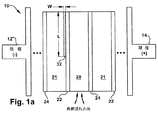
ここで本発明の実施形態を図示した図1a〜図1dを参照する。これらの図には、イオン削減希釈室20が濃縮室21間に配置された構成の貫流電気脱イオン(EDI)モジュール10が示されている。図示の便宜上、1つの希釈室20に1対の濃縮室21が隣接した構造を示す。しかし、本発明は、本発明の要旨から逸脱することなく、当業界で周知の方法で1つもしくは2つ以上の交互の希釈/濃縮セル対モジュールを陽極14と陰極12間に配置した構成のEDI装置でも実施可能であることが明らかである。
Reference is now made to FIGS. 1 a-1 d illustrating an embodiment of the present invention. In these figures, a once-through electrodeionization (EDI)
図1a〜図1dにおいて、カチオン選択性膜22及びアニオン選択性膜24が希釈室20の両周囲側面に配置されている。一方、陽極14及び陰極12がモジュール10の両端部に配置され、電圧を1以上の希釈室20及び濃縮室21に交差方向に供給する。代表的には、希釈室20及び濃縮室21には電気活性な樹脂ビーズ(図示せず)を充填して、当業界で既知の態様でのイオン交換を達成することができる。流体を希釈室20の入口(即ち、図の下部)に希釈流れ方向矢印で示す方向に導く。一方、精製された流体が希釈室20の出口(即ち、図の上部)から出てくる。
In FIGS. 1 a to 1 d, a cation
図1a〜図1dに、抵抗成分32を希釈室20の出口領域近くに配置した、本発明の実施形態を図示する。ここに開示した実施形態を説明するために、実験用に、抵抗成分32として所定の長さL及び表面構造厚さWを有するポリマーメッシュを選択した。抵抗成分32の長さLが室の全長の約50%であるのが好ましいが、抵抗成分の一部が入口領域の一部も覆うか否かに関係なく、抵抗成分が室の出口領域の近傍に位置する限りで、50%より多いか50%より少ない部分長さを使用してもよく、本発明の要旨から逸脱しない。さらに、抵抗成分32については、出口領域近くでビーズ/膜界面に隣接する種々の位置に配置した様々な長さのメッシュ片と組み合わせて、様々な厚さ及び/又は表面構造(即ち、メッシュ密度、開口度)を使用しても、所望の結果を得ることが可能であることも理解される。さらに、上述したように、非メッシュ型抵抗成分32、例えばフィルムシート又は実質的に非導電性粒子の層を与えるように構成された他の適当な材料も本発明で使用できる。また、種々の長さの小片を(膜の希釈側もしくは濃縮側いずれかで)イオン選択性膜22,24の片方もしくは両方上の種々の位置に適切に配置して、希釈室20内の所定区域の導電率を変えることもでき、本発明の要旨から逸脱しない。
FIGS. 1 a-1 d illustrate an embodiment of the present invention in which a
図1aに示す一実施形態では、抵抗成分32がカチオン膜22の濃縮側でカチオン膜22の出口半部に配置されている。或いはまた、図1bに示すように、抵抗成分32をカチオン膜22の希釈側に配置してもよい。図1c及び1dに示す他の実施形態では、抵抗成分32がアニオン膜24の濃縮側(図1c)又は希釈側(図1d)でアニオン膜24の出口半部に配置されている。なお、図示の実施形態の種々の組合せや並べ替えも使用でき、本発明の要旨から逸脱しない。
In one embodiment shown in FIG. 1 a, a
ここに開示した実施形態のいずれにおいても、本発明は、希釈室もしくは濃縮室内いずれかでビーズ/ビーズ界面間にて出口領域近くでイオン交換床に抵抗成分を付加することにより達成できる。このことは、ビーズを部分的に被覆する溶融ポリマーを用いる例で実証され、溶融ポリマーを用いる結果として、ビーズ間のビーズ/ビーズ界面を減少させ、これによりビーズ間の電気抵抗を増加し、またそれに伴って出口領域の電気抵抗を入口領域に対して増加する。イオン交換ビーズの外に、抵抗成分を出口領域近くで、他のタイプのイオン交換媒体粒子、例えばイオン交換繊維もしくはフィルム粒子間に配置して、出口領域の電気抵抗を入口領域に対して増加することによっても、本発明を実施できることが分かる。さらに、本明細書に記載の実施形態のいずれにおいても、イオン交換床の特定の区域における単位体積当たりのイオン交換材料の質量を変えてビーズ及び/又は粒子接触圧力を増減することにより、イオン交換床の導電率を変更することができる。 In any of the embodiments disclosed herein, the present invention can be achieved by adding a resistance component to the ion exchange bed near the exit region between the bead / bead interface in either the dilution chamber or the concentration chamber. This is demonstrated in the example using a molten polymer that partially coats the beads, and as a result of using the molten polymer, it reduces the bead / bead interface between the beads, thereby increasing the electrical resistance between the beads, and Accordingly, the electrical resistance of the exit area is increased with respect to the entrance area. In addition to the ion exchange beads, a resistive component is placed near the exit region and between other types of ion exchange media particles, such as ion exchange fibers or film particles, to increase the electrical resistance of the exit region relative to the entrance region. This also shows that the present invention can be implemented. Further, in any of the embodiments described herein, ion exchange is achieved by varying the mass of ion exchange material per unit volume in a particular area of the ion exchange bed to increase or decrease the bead and / or particle contact pressure. The conductivity of the floor can be changed.
作動時には、精製すべき液体を希釈室20の入口領域に希釈流れ方向矢印で示される方向に供給する。一方、精製された水は希釈室20の出口領域から出てくる。電界をモジュール10の反対端にある陽極14及び陰極12にかける。すると、電流は当業界で周知の態様にて流体流れの方向に直角に流れ、かくして溶解されたカチオン及びアニオン成分がイオン交換樹脂ビーズまたは他のイオン交換繊維もしくはフィルム粒子(図示せず)から、対応する電極12,14の方向に移動する。カチオン成分はカチオン透過膜22を通って隣接する陰極対面イオン濃縮室21に移動する。アニオン成分のプロセスも同様であるが、反対方向に起こり、つまりアニオン成分はアニオン透過膜24を通って陽極対面イオン濃縮室21に移動する。このようにして、希釈室20を通過する流体からイオン成分が削減(除去)され、これにより形成される高純度流体流れが希釈室20の出口領域から出て行く。
In operation, the liquid to be purified is supplied to the inlet region of the
以下に実施例を示して、本発明の広い適用可能性を具体的に示すが、これらは本発明の範囲を限定するものではない。 The following examples illustrate the wide applicability of the present invention, but these do not limit the scope of the invention.
実施例1
NaHCO3をCaCO3として20ppmの全交換可能アニオン(TEA)濃度にて含有し、また250ppbのSiO2を含有する水溶液を、図2aに示すように従来のEDIモジュールに供給した。実施例1では、希釈室20から出てくる流体が、約15〜18ppbの残留SiO2を含有することが確認された。希釈室20全域にわたって測定した区域1〜4における電流分布を図2aに示す。電流分布は、区域1=11%、区域2=18%、区域3=30%、区域4=41%であった。したがって、電流の約71%が希釈室の出口半部(即ち、区域3及び4)近くに存在する一方、電流の約29%が希釈室の入口半部(即ち、区域1及び2)近くに存在することが明らかである。このように電流分布が希釈室の出口領域に向かってアンバランスになっていることは、希釈室を通る流れ長さの大きな割合が高イオン化種の除去に向けられ、一方出口領域近くの流れ長さの部分は弱イオン化種、即ちSiO2を除去するのに用いられていることを示している。
Example 1
An aqueous solution containing NaHCO 3 as CaCO 3 at a total exchangeable anion (TEA) concentration of 20 ppm and containing 250 ppb SiO 2 was fed to a conventional EDI module as shown in FIG. 2a. In Example 1, it was confirmed that the fluid coming out of the
これに対して、抵抗成分32が希釈室20の出口領域近くに配置された、本発明にしたがって構成されたEDIモジュールでは、図2bに示すように、希釈室の区域1〜4における電流分布が効果的に変更されている。本例では、電流分布が室全体にわたってもっとバランスよくなっていることが分かる。電流分布は、区域1=17%、区域2=33%、区域3=24%、区域4=26%であった。したがって、電流分布は希釈室20の入口及び出口領域間でよくバランスがとれており、電流の約50%が区域1及び2(即ち入口領域)に分布し、電流の約50%が区域3及び4(即ち出口領域)に分布している。電流分布が改良されているせいで、希釈室20の出口側から出てくる流体は、残留SiO2の量が約5〜6ppbと減少していることが分かった。したがって、本発明による抵抗成分32を設けたEDI装置は、希釈室20全体における電流分布を効果的に改良し、その結果、装置から出てくる流体のSiO2含量が約15〜18ppbから約5〜6ppbに減少した。これらの結果から、本発明にしたがって構成したメッシュ状抵抗成分32を用いて、電流を入口領域(区域1及び2)に向かってシフトし、それにより全体的脱イオン性能を高めることに成功したことが分かる。
In contrast, in an EDI module constructed in accordance with the present invention in which the
図2a及び2bに示すように、本発明にしたがって(図2bに示すように)抵抗成分32を設けたEDI装置の有効性を、(図2aに示すように)抵抗成分を設けない従来のEDI装置と比較評価した。この目的で、実施例1では、抵抗成分32を希釈室の出口半部においてカチオン膜22の希釈側に配置した。なお、抵抗成分32を希釈室の出口半部近くでカチオン膜側もしくはアニオン膜側いずれに配置しても同等の結果を達成できる。抵抗成分32は、希釈室20の全長の約50%を覆う長さを有するポリマーメッシュであった。しかし、50%より多いか50%より少ない部分長さを使用しても、本発明の要旨から逸脱しない。図2bの希釈室20の区域1〜4における電流分布割合から分かるように、抵抗成分32は、希釈室20/カチオン膜22界面におけるビーズ/膜接触面積を限定することにより、希釈室20の出口領域の抵抗を増加するのに有効であることが明らかである。その結果、図2aと図2bの区域1〜4における電流分布割合の比較から証明される通り、希釈室の入口半部(即ち、区域1,2)における電流分布割合が増加し、一方抵抗成分32に帰せられる出口半部の高抵抗のために、出口半部(即ち、区域3,4)における電流分布割合が減少している。その結果、装置から出てくる流体のSiO2含量が約15〜18ppbから約5〜6ppbに減少したという実施例1の結果が証明するように、入口領域の高い電流割合により全体的脱イオン性能が改良されている。
As shown in FIGS. 2a and 2b, the effectiveness of an EDI device provided with a
以上、本発明を代表的な実施形態について説明したが、本発明の要旨から逸脱することなく、種々の変更や置き換えが可能であるので、本発明は提示した細部に限定されるものではない。ここに開示した本発明の変更例や均等物は、通常の実験だけで当業者に想起でき、このような変更例や均等物も特許請求の範囲に規定された本発明の要旨の範囲内に包含される。 While the present invention has been described with reference to the exemplary embodiments, various modifications and replacements can be made without departing from the spirit of the present invention, and the present invention is not limited to the details presented. Modifications and equivalents of the present invention disclosed herein can be conceived to those skilled in the art by ordinary experiment alone, and such modifications and equivalents are within the scope of the invention as defined in the claims. Is included.
10 モジュール
20 希釈室
21 濃縮室
22 カチオン選択性透過膜
24 アニオン選択性透過膜
32 抵抗成分
10
Claims (13)
イオン選択性透過膜間に配置された入口領域及び出口領域を有する1以上の希釈室と、
前記イオン選択性透過膜の1以上に隣接配置された1以上の濃縮室と、
前記出口領域の電気抵抗を前記入口領域に比べて増加させて、前記入口領域での電流の分布を増加させるため、前記出口領域付近で前記1以上のイオン選択性透過膜に連結された1以上の抵抗成分と
を含む電気脱イオン装置。 An electrodeionization device for removing ions from a liquid passing through the interior,
One or more dilution chambers having an inlet region and an outlet region disposed between the ion selective permeable membranes;
One or more concentration chambers disposed adjacent to one or more of the ion selective permeable membranes;
One or more coupled to the one or more ion selective permeable membranes near the outlet region to increase the electrical resistance of the outlet region compared to the inlet region and increase the current distribution in the inlet region. a resistance component including electrodeionization apparatus.
イオン選択性透過膜間に配置された入口領域及び出口領域を有する1以上の希釈室を設け、
前記イオン選択性透過膜の1以上に隣接配置された1以上の濃縮室を設け、
前記出口領域付近で前記1以上のイオン選択性透過膜に1以上の抵抗成分を連結し、これにより前記出口領域の電気抵抗を前記入口領域に対して増加するようにし、
液体を前記希釈室に入口領域から出口領域へ流通させ、
前記液体の流れ方向に交差して前記希釈室に電界をかける工程
を含んでおり、前記抵抗成分が前記入口領域に流れる電流の分布を前記出口領域に対して増加させ、前記入口領域での電流分布を増加させる、方法。A method of removing ions from a liquid with an electrodeionization device, the method comprising:
Providing one or more dilution chambers having an inlet region and an outlet region disposed between the ion selective permeable membranes;
Providing one or more concentrating chambers adjacent to one or more of the ion selective permeable membranes;
Coupling one or more resistive components to the one or more ion selective permeable membranes near the outlet region, thereby increasing the electrical resistance of the outlet region relative to the inlet region;
Flowing liquid through the dilution chamber from the inlet region to the outlet region;
The step of applying an electric field to said dilution chamber to cross the flow direction of the liquid and Nde free, increases the distribution of current the resistance component flows in the inlet region to the outlet region, the current in the inlet region A way to increase the distribution .
イオン選択性透過膜間に配置された入口領域及び出口領域を有する希釈室を設け、
1以上の濃縮室を前記イオン選択性透過膜の1つに連結し、
前記室の1以上に複数のイオン交換粒子を供給し、
2つ以上のイオン交換粒子間に前記出口領域付近で1以上の抵抗成分を設け、これにより前記出口領域の電気抵抗を前記入口領域に比べて増加するようにし、
液体を前記希釈室に入口領域から出口領域へ流通させ、
前記液体の流れ方向に交差して前記希釈室に電界をかける工程
を含んでおり、前記抵抗成分が前記入口領域に流れる電流の分布を前記出口領域に比べて増加させ、前記入口領域での電流分布を増加させる、方法。A method of removing ions from a liquid with an electrodeionization device, the method comprising:
Providing a dilution chamber having an inlet region and an outlet region disposed between the ion selective permeable membranes;
Connecting one or more concentration chambers to one of the ion selective permeable membranes;
Supplying a plurality of ion exchange particles to one or more of the chambers;
Providing one or more resistive components in the vicinity of the exit region between two or more ion exchange particles, thereby increasing the electrical resistance of the exit region compared to the entrance region;
Flowing liquid through the dilution chamber from the inlet region to the outlet region;
The step of applying an electric field to said dilution chamber to cross the flow direction of the liquid and Nde including the distribution of current the resistance component flows in the inlet region is increased as compared to the outlet region, the current in the inlet region A way to increase the distribution .
Applications Claiming Priority (3)
| Application Number | Priority Date | Filing Date | Title |
|---|---|---|---|
| US11/445,954 | 2006-06-02 | ||
| US11/445,954 US7427342B2 (en) | 2006-06-02 | 2006-06-02 | Method and apparatus for shifting current distribution in electrodeionization systems |
| PCT/US2007/067646 WO2007143296A2 (en) | 2006-06-02 | 2007-04-27 | Method and apparatus for shifting current distribution in electrodeionization systems |
Publications (3)
| Publication Number | Publication Date |
|---|---|
| JP2009539578A JP2009539578A (en) | 2009-11-19 |
| JP2009539578A5 JP2009539578A5 (en) | 2011-04-28 |
| JP4913212B2 true JP4913212B2 (en) | 2012-04-11 |
Family
ID=38752643
Family Applications (1)
| Application Number | Title | Priority Date | Filing Date |
|---|---|---|---|
| JP2009513356A Active JP4913212B2 (en) | 2006-06-02 | 2007-04-27 | Method and apparatus for shifting current distribution in an electrodeionization system |
Country Status (13)
| Country | Link |
|---|---|
| US (1) | US7427342B2 (en) |
| EP (1) | EP2029262B1 (en) |
| JP (1) | JP4913212B2 (en) |
| KR (1) | KR101443925B1 (en) |
| CN (1) | CN101454067B (en) |
| AU (1) | AU2007257074B2 (en) |
| BR (1) | BRPI0711522A2 (en) |
| CA (1) | CA2653014C (en) |
| ES (1) | ES2387414T3 (en) |
| MX (1) | MX2008015223A (en) |
| MY (1) | MY146075A (en) |
| TW (1) | TWI432254B (en) |
| WO (1) | WO2007143296A2 (en) |
Families Citing this family (31)
| Publication number | Priority date | Publication date | Assignee | Title |
|---|---|---|---|---|
| DE10303974A1 (en) | 2003-01-31 | 2004-08-05 | Abbott Gmbh & Co. Kg | Amyloid β (1-42) oligomers, process for their preparation and their use |
| CA2631195C (en) | 2005-11-30 | 2016-04-05 | Abbott Laboratories | Monoclonal antibodies against amyloid beta protein and uses thereof |
| CN101432302A (en) | 2005-11-30 | 2009-05-13 | 艾博特公司 | Anti-a globulomer antibodies, antigen-binding moieties thereof, corresponding hybridomas, nucleic acids, vectors, host cells, methods of producing said antibodies, compositions comprising said antibod |
| PT2361638E (en) | 2005-12-12 | 2014-04-17 | Ac Immune Sa | A beta 1-42 specific monoclonal antibodies with therapeutic properties |
| US20080067069A1 (en) | 2006-06-22 | 2008-03-20 | Siemens Water Technologies Corp. | Low scale potential water treatment |
| EP2046833B9 (en) | 2006-07-14 | 2014-02-19 | AC Immune S.A. | Humanized antibody against amyloid beta |
| WO2008048656A2 (en) * | 2006-10-18 | 2008-04-24 | Kinetico Incorporated | Electroregeneration apparatus and water treatment method |
| US8455626B2 (en) | 2006-11-30 | 2013-06-04 | Abbott Laboratories | Aβ conformer selective anti-aβ globulomer monoclonal antibodies |
| EP2124952A2 (en) | 2007-02-27 | 2009-12-02 | Abbott GmbH & Co. KG | Method for the treatment of amyloidoses |
| US8048420B2 (en) | 2007-06-12 | 2011-11-01 | Ac Immune S.A. | Monoclonal antibody |
| US8613923B2 (en) | 2007-06-12 | 2013-12-24 | Ac Immune S.A. | Monoclonal antibody |
| CA2701793C (en) | 2007-10-05 | 2017-04-25 | Genentech, Inc. | Use of anti-amyloid beta antibody in ocular diseases |
| MX2010005876A (en) | 2007-11-30 | 2010-06-15 | Siemens Water Tech Corp | Systems and methods for water treatment. |
| JP5015989B2 (en) * | 2009-03-25 | 2012-09-05 | オルガノ株式会社 | Method for producing electric deionized water production apparatus |
| JP5015990B2 (en) * | 2009-03-25 | 2012-09-05 | オルガノ株式会社 | Electric deionized water production equipment |
| US8987419B2 (en) | 2010-04-15 | 2015-03-24 | AbbVie Deutschland GmbH & Co. KG | Amyloid-beta binding proteins |
| JP5719842B2 (en) | 2010-06-03 | 2015-05-20 | オルガノ株式会社 | Electric deionized water production equipment |
| SG187173A1 (en) | 2010-07-30 | 2013-02-28 | Ac Immune Sa | Safe and functional humanized anti beta-amyloid antibody |
| MX358739B (en) | 2010-08-14 | 2018-09-03 | Abbvie Inc Star | Amyloid-beta binding proteins. |
| JP5695926B2 (en) * | 2011-02-08 | 2015-04-08 | オルガノ株式会社 | Electric deionized water production equipment |
| CN103732544B (en) | 2011-08-04 | 2016-03-30 | 奥加诺株式会社 | For the preparation of the electric deionizer of deionized water |
| US9339765B2 (en) * | 2011-09-16 | 2016-05-17 | General Electric Company | Electrodialysis method and apparatus for passivating scaling species |
| US9010361B2 (en) | 2011-10-27 | 2015-04-21 | Pentair Residential Filtration, Llc | Control valve assembly |
| US8671985B2 (en) | 2011-10-27 | 2014-03-18 | Pentair Residential Filtration, Llc | Control valve assembly |
| US8961770B2 (en) | 2011-10-27 | 2015-02-24 | Pentair Residential Filtration, Llc | Controller and method of operation of a capacitive deionization system |
| US9637397B2 (en) | 2011-10-27 | 2017-05-02 | Pentair Residential Filtration, Llc | Ion removal using a capacitive deionization system |
| US9695070B2 (en) | 2011-10-27 | 2017-07-04 | Pentair Residential Filtration, Llc | Regeneration of a capacitive deionization system |
| US9724645B2 (en) | 2012-02-02 | 2017-08-08 | Tangent Company Llc | Electrochemically regenerated water deionization |
| GB201312491D0 (en) * | 2013-07-12 | 2013-08-28 | Fujifilm Mfg Europe Bv | Electrodialysis |
| JP6532554B1 (en) * | 2018-01-19 | 2019-06-19 | オルガノ株式会社 | Electric deionized water production equipment |
| KR20230165576A (en) * | 2022-05-27 | 2023-12-05 | 주식회사 켈스 | Selective concentration filter based on cell membrane component and manufacturing method thereof |
Family Cites Families (12)
| Publication number | Priority date | Publication date | Assignee | Title |
|---|---|---|---|---|
| WO1996029133A1 (en) * | 1995-03-23 | 1996-09-26 | Ionics, Incorporated | Improvements in membrane processes including electrodialysis |
| US5720971A (en) * | 1995-07-05 | 1998-02-24 | Her Majesty The Queen In Right Of Canada, As Represented By The Department Of Agriculture And Agri-Food Canada | Enzyme additives for ruminant feeds |
| US5868915A (en) * | 1996-09-23 | 1999-02-09 | United States Filter Corporation | Electrodeionization apparatus and method |
| EP0892677B1 (en) * | 1996-11-12 | 2001-11-28 | United States Filter Corporation | Electrodeionization apparatus and method |
| WO1998051620A1 (en) | 1997-05-09 | 1998-11-19 | Usf Filtration And Separations Group Inc. | Purification of a liquid stream |
| CN1117704C (en) * | 1997-08-14 | 2003-08-13 | 王方 | Method for preparing soft water by electro-deionization and its device |
| US6284124B1 (en) * | 1999-01-29 | 2001-09-04 | United States Filter Corporation | Electrodeionization apparatus and method |
| US6274019B1 (en) * | 2000-03-08 | 2001-08-14 | Organo Corporation | Electrodeionization apparatus |
| US6391178B1 (en) * | 2000-07-13 | 2002-05-21 | Millipore Corporation | Electrodeionization system |
| US6649037B2 (en) * | 2001-05-29 | 2003-11-18 | United States Filter Corporation | Electrodeionization apparatus and method |
| JP3864891B2 (en) * | 2002-07-01 | 2007-01-10 | 栗田工業株式会社 | Electric deionizer |
| JP5098216B2 (en) * | 2006-05-08 | 2012-12-12 | 日本錬水株式会社 | Electric regenerative pure water production apparatus and pure water production method |
-
2006
- 2006-06-02 US US11/445,954 patent/US7427342B2/en active Active
-
2007
- 2007-04-27 CA CA2653014A patent/CA2653014C/en active Active
- 2007-04-27 CN CN2007800195559A patent/CN101454067B/en active Active
- 2007-04-27 AU AU2007257074A patent/AU2007257074B2/en not_active Ceased
- 2007-04-27 EP EP07761469A patent/EP2029262B1/en active Active
- 2007-04-27 MX MX2008015223A patent/MX2008015223A/en active IP Right Grant
- 2007-04-27 ES ES07761469T patent/ES2387414T3/en active Active
- 2007-04-27 BR BRPI0711522-9A patent/BRPI0711522A2/en not_active IP Right Cessation
- 2007-04-27 KR KR1020087029406A patent/KR101443925B1/en active IP Right Grant
- 2007-04-27 WO PCT/US2007/067646 patent/WO2007143296A2/en active Application Filing
- 2007-04-27 JP JP2009513356A patent/JP4913212B2/en active Active
- 2007-05-04 TW TW096115927A patent/TWI432254B/en active
-
2008
- 2008-11-27 MY MYPI20084828A patent/MY146075A/en unknown
Also Published As
| Publication number | Publication date |
|---|---|
| CN101454067A (en) | 2009-06-10 |
| EP2029262B1 (en) | 2012-06-13 |
| KR20090014366A (en) | 2009-02-10 |
| MX2008015223A (en) | 2008-12-12 |
| CA2653014C (en) | 2015-11-24 |
| TW200803967A (en) | 2008-01-16 |
| EP2029262A2 (en) | 2009-03-04 |
| TWI432254B (en) | 2014-04-01 |
| WO2007143296A3 (en) | 2008-02-28 |
| US20070278099A1 (en) | 2007-12-06 |
| MY146075A (en) | 2012-06-29 |
| AU2007257074A1 (en) | 2007-12-13 |
| JP2009539578A (en) | 2009-11-19 |
| BRPI0711522A2 (en) | 2011-11-01 |
| ES2387414T3 (en) | 2012-09-21 |
| CN101454067B (en) | 2012-07-04 |
| CA2653014A1 (en) | 2007-12-13 |
| WO2007143296A2 (en) | 2007-12-13 |
| KR101443925B1 (en) | 2014-09-23 |
| AU2007257074B2 (en) | 2012-06-21 |
| US7427342B2 (en) | 2008-09-23 |
Similar Documents
| Publication | Publication Date | Title |
|---|---|---|
| JP4913212B2 (en) | Method and apparatus for shifting current distribution in an electrodeionization system | |
| JP5213864B2 (en) | Arrangement of ion exchange material in electrodeionization equipment | |
| EP2208523B1 (en) | Electrodeionization device with hydrodynamic flow splitting | |
| EP2708514B1 (en) | Regenerative demineralizing apparatus | |
| JP2002535128A (en) | Electrodeionizer and electrodeionization method | |
| EP2122012A1 (en) | Devices and methods for acid and base generation | |
| JP4400218B2 (en) | Electric deionization apparatus and deionization method | |
| JP2020078772A (en) | Electrodeionization device and method for producing deionized water using the same | |
| TW200414922A (en) | Electrodeionization apparatus | |
| JP5940387B2 (en) | Electric deionized water production apparatus and deionized water production method | |
| CN111615497B (en) | Electric deionizing device for producing deionized water | |
| JP2002205071A (en) | Electric deionized water manufacturing apparatus and method of manufacturing deionized water | |
| JP2023524956A (en) | Improvement of Chlorine Tolerance of Continuous Electrodeionization Module | |
| JP6034736B2 (en) | Electric deionized water production equipment | |
| WO2022118522A1 (en) | Electric deionization device and method for producing deionized water | |
| JP7077172B2 (en) | Electric deionized water production equipment | |
| KR20230107642A (en) | Electrodeionization configuration for enhanced removal of weakly ionized species | |
| TW202406857A (en) | Electrodeionized water production apparatus and method for operating same | |
| JP2016123914A (en) | Electric deionization device, and electric deionization treatment method |
Legal Events
| Date | Code | Title | Description |
|---|---|---|---|
| A521 | Request for written amendment filed |
Free format text: JAPANESE INTERMEDIATE CODE: A523 Effective date: 20100406 |
|
| A621 | Written request for application examination |
Free format text: JAPANESE INTERMEDIATE CODE: A621 Effective date: 20100406 |
|
| RD04 | Notification of resignation of power of attorney |
Free format text: JAPANESE INTERMEDIATE CODE: A7424 Effective date: 20100406 |
|
| A521 | Request for written amendment filed |
Free format text: JAPANESE INTERMEDIATE CODE: A523 Effective date: 20110304 |
|
| A977 | Report on retrieval |
Free format text: JAPANESE INTERMEDIATE CODE: A971007 Effective date: 20111209 |
|
| TRDD | Decision of grant or rejection written | ||
| A01 | Written decision to grant a patent or to grant a registration (utility model) |
Free format text: JAPANESE INTERMEDIATE CODE: A01 Effective date: 20111220 |
|
| A01 | Written decision to grant a patent or to grant a registration (utility model) |
Free format text: JAPANESE INTERMEDIATE CODE: A01 |
|
| A61 | First payment of annual fees (during grant procedure) |
Free format text: JAPANESE INTERMEDIATE CODE: A61 Effective date: 20120118 |
|
| R150 | Certificate of patent or registration of utility model |
Ref document number: 4913212 Country of ref document: JP Free format text: JAPANESE INTERMEDIATE CODE: R150 Free format text: JAPANESE INTERMEDIATE CODE: R150 |
|
| FPAY | Renewal fee payment (event date is renewal date of database) |
Free format text: PAYMENT UNTIL: 20150127 Year of fee payment: 3 |
|
| R250 | Receipt of annual fees |
Free format text: JAPANESE INTERMEDIATE CODE: R250 |
|
| R250 | Receipt of annual fees |
Free format text: JAPANESE INTERMEDIATE CODE: R250 |
|
| R250 | Receipt of annual fees |
Free format text: JAPANESE INTERMEDIATE CODE: R250 |
|
| R250 | Receipt of annual fees |
Free format text: JAPANESE INTERMEDIATE CODE: R250 |
|
| S111 | Request for change of ownership or part of ownership |
Free format text: JAPANESE INTERMEDIATE CODE: R313113 |
|
| R350 | Written notification of registration of transfer |
Free format text: JAPANESE INTERMEDIATE CODE: R350 |
|
| R250 | Receipt of annual fees |
Free format text: JAPANESE INTERMEDIATE CODE: R250 |
|
| R250 | Receipt of annual fees |
Free format text: JAPANESE INTERMEDIATE CODE: R250 |
|
| R250 | Receipt of annual fees |
Free format text: JAPANESE INTERMEDIATE CODE: R250 |
|
| R250 | Receipt of annual fees |
Free format text: JAPANESE INTERMEDIATE CODE: R250 |
|
| R250 | Receipt of annual fees |
Free format text: JAPANESE INTERMEDIATE CODE: R250 |
|
| R250 | Receipt of annual fees |
Free format text: JAPANESE INTERMEDIATE CODE: R250 |