JP4912979B2 - Image processing apparatus, image processing method, and program - Google Patents
Image processing apparatus, image processing method, and program Download PDFInfo
- Publication number
- JP4912979B2 JP4912979B2 JP2007210187A JP2007210187A JP4912979B2 JP 4912979 B2 JP4912979 B2 JP 4912979B2 JP 2007210187 A JP2007210187 A JP 2007210187A JP 2007210187 A JP2007210187 A JP 2007210187A JP 4912979 B2 JP4912979 B2 JP 4912979B2
- Authority
- JP
- Japan
- Prior art keywords
- edge
- color difference
- pixel
- interpolation
- signal
- Prior art date
- Legal status (The legal status is an assumption and is not a legal conclusion. Google has not performed a legal analysis and makes no representation as to the accuracy of the status listed.)
- Active
Links
- 238000012545 processing Methods 0.000 title claims description 63
- 238000003672 processing method Methods 0.000 title claims description 4
- 238000003384 imaging method Methods 0.000 claims description 36
- 238000009499 grossing Methods 0.000 claims description 17
- 230000001419 dependent effect Effects 0.000 claims description 5
- 230000035945 sensitivity Effects 0.000 claims description 5
- 230000003595 spectral effect Effects 0.000 claims description 5
- 238000004364 calculation method Methods 0.000 description 58
- 230000015654 memory Effects 0.000 description 41
- 238000000034 method Methods 0.000 description 31
- 230000002093 peripheral effect Effects 0.000 description 31
- 230000008569 process Effects 0.000 description 17
- 238000012508 change request Methods 0.000 description 9
- 230000003287 optical effect Effects 0.000 description 7
- 238000010586 diagram Methods 0.000 description 5
- 230000000694 effects Effects 0.000 description 5
- 238000001914 filtration Methods 0.000 description 5
- 230000006870 function Effects 0.000 description 5
- 230000006835 compression Effects 0.000 description 3
- 238000007906 compression Methods 0.000 description 3
- 239000000470 constituent Substances 0.000 description 3
- 239000011159 matrix material Substances 0.000 description 3
- 238000005070 sampling Methods 0.000 description 3
- 238000006243 chemical reaction Methods 0.000 description 2
- 230000009467 reduction Effects 0.000 description 2
- 238000012935 Averaging Methods 0.000 description 1
- 239000003086 colorant Substances 0.000 description 1
- 238000012937 correction Methods 0.000 description 1
- 230000007547 defect Effects 0.000 description 1
- 238000012986 modification Methods 0.000 description 1
- 230000004048 modification Effects 0.000 description 1
Images


Classifications
-
- H—ELECTRICITY
- H04—ELECTRIC COMMUNICATION TECHNIQUE
- H04N—PICTORIAL COMMUNICATION, e.g. TELEVISION
- H04N23/00—Cameras or camera modules comprising electronic image sensors; Control thereof
- H04N23/80—Camera processing pipelines; Components thereof
- H04N23/84—Camera processing pipelines; Components thereof for processing colour signals
- H04N23/843—Demosaicing, e.g. interpolating colour pixel values
-
- H—ELECTRICITY
- H04—ELECTRIC COMMUNICATION TECHNIQUE
- H04N—PICTORIAL COMMUNICATION, e.g. TELEVISION
- H04N2209/00—Details of colour television systems
- H04N2209/04—Picture signal generators
- H04N2209/041—Picture signal generators using solid-state devices
- H04N2209/042—Picture signal generators using solid-state devices having a single pick-up sensor
- H04N2209/045—Picture signal generators using solid-state devices having a single pick-up sensor using mosaic colour filter
- H04N2209/046—Colour interpolation to calculate the missing colour values
Landscapes
- Engineering & Computer Science (AREA)
- Multimedia (AREA)
- Signal Processing (AREA)
- Color Television Image Signal Generators (AREA)
- Studio Devices (AREA)
Description
本発明は、異なる分光感度を有する複数種類の撮像素子を単一面上に規則配列した撮像デバイスで得たカラー撮像信号を処理する画像処理装置、画像処理方法及びプログラムに関する。 The present invention relates to an image processing apparatus, an image processing method, and a program for processing a color imaging signal obtained by an imaging device in which a plurality of types of imaging elements having different spectral sensitivities are regularly arranged on a single surface.
カラー画像を電気的に撮像する装置としては、1つの画素位置で3つの色(R,G,B)信号を同時に得ることができる3板撮像素子構成のものと、1つの画素位置毎に3つの色信号のうちの1つの色信号しか得ることができない単板撮像素子構成のものに大別される。現在市販されているデジタルカメラは単板撮像素子構成が一般的である。 As an apparatus for electrically capturing a color image, a device having a three-plate image sensor that can simultaneously obtain three color (R, G, B) signals at one pixel position, and three for each pixel position. It is roughly divided into those having a single-plate image pickup device configuration that can obtain only one of the two color signals. A digital camera currently on the market generally has a single-plate image sensor configuration.
3板撮像素子構成は、構造が複雑で部品点数も多くなるために高価格ではあるが、撮像画像の各画素位置で3つの色信号を同時に得ることができるので、一般的に高画質である。 The three-plate image pickup device configuration is expensive because the structure is complicated and the number of parts is large, but since three color signals can be obtained simultaneously at each pixel position of the picked-up image, the image quality is generally high. .
一方、単板撮像素子構成は構造が簡単であるが、3つの色信号を得るために画素毎にR,G,Bフィルタを例えば図14に示すベイヤ配列と称されるモザイク状に配置する必要があり、撮像画像の各画素位置で単一色成分の信号のみしか得ることができない。 On the other hand, the structure of the single-plate image sensor is simple, but in order to obtain three color signals, it is necessary to arrange R, G, and B filters for each pixel in a mosaic shape called the Bayer array shown in FIG. Only a single color component signal can be obtained at each pixel position of the captured image.
このようなベイヤ配列においては、各画素位置で欠落している色信号を周辺の画素位置の色信号を用いて補間することで、画素当り3つの色信号を得ている。 In such a Bayer array, three color signals per pixel are obtained by interpolating the missing color signals at each pixel position using the color signals at the surrounding pixel positions.
しかしながら、画像中のエッジなどの高い空間周波数を持った撮像領域では、G信号に対してRとB信号のサンプリング間隔が異なることに伴い、G信号で表現可能な高い空間周波数がRとB信号では低周波数側に折り返してしまうために、各色信号で補間処理したのではエッジ周辺部等で偽色と称される本来無い色が発生するという不具合がある。 However, in an imaging region having a high spatial frequency such as an edge in an image, the sampling frequency of the R and B signals is different from that of the G signal. However, since the signal is folded back to the low frequency side, there is a problem that an inherent color called a false color is generated in the peripheral portion of the edge or the like when interpolation processing is performed with each color signal.
このような偽色を低減する最も簡単な方法は、ベイヤ配列のR信号あるいはB信号のサンプリング間隔が再現できる空間周波数までレンズ、あるいは光学ローパスフィルタの特性を落とした画像を撮像素子上に結像させることである。 The simplest method for reducing such false colors is to form an image on the image sensor with the characteristics of the lens or optical low-pass filter reduced to a spatial frequency that can reproduce the sampling interval of the R signal or B signal in the Bayer array. It is to let you.
ただし、この方法での撮像画像は、本来再現可能な空間周波数の半分しか得られないことになり、解像度の低いボケた画像となってしまうという不具合が発生する。そのため、撮像素子上に結像させる画像解像度がG信号のサンプリング間隔で折り返し歪みによるモワレが発生しない空間周波数特性となるように光学系を設計するのが一般的である。 However, only half of the spatial frequency that can be originally reproduced can be obtained with a captured image by this method, resulting in a problem that the image is blurred with low resolution. Therefore, the optical system is generally designed so that the image resolution formed on the image sensor has a spatial frequency characteristic that does not cause moire due to aliasing distortion at the G signal sampling interval.
このような光学系を用い、且つ偽色低減を行なう方法が今までにも種々提案されている。 Various methods for using such an optical system and performing false color reduction have been proposed.
その例として特許文献1では、画像の局所領域のG信号類似度やG信号とR信号、あるいはG信号とB信号の色信号間類似度の方向依存に適応して補間フィルタを切り替える方法が提案されている。
As an example,
すなわち特許文献1では、欠落しているG信号の画素位置に対して周辺の上下左右計4つのG信号間の水平、垂直方向の類似度を算出し、予め決定された閾値との比較により、G信号を使った3つの線形補間方法の中から1つ選択する。
That is, in
図15にこの補間方法を示す。図15(A)は、中心となるG信号の値Xに対し、垂直方向で隣接するG信号の類似度|G1−G2|を算出し、さらに線形補間演算「(G1+G2)/2」を行なう方法である。図15(B)は、中心となるG信号の値Xに対し、水平方向で隣接するG信号の類似度|G3−G4|を算出し、さらに線形補間演算「(G3+G4)/2」を行なう方法である。そして、図15(C)は、中心となるG信号の値Xに対し、垂直水平各方向で隣接するG信号の類似度|G1−G2|,|G3−G4|を算出し、さらに線形補間演算「(G1+G2+G3+G4)/4」を行なう方法である。 FIG. 15 shows this interpolation method. FIG. 15A calculates the similarity | G1-G2 | of the G signals adjacent in the vertical direction with respect to the value X of the central G signal, and further performs a linear interpolation operation “(G1 + G2) / 2”. Is the method. FIG. 15B calculates the similarity | G3-G4 | of adjacent G signals in the horizontal direction with respect to the value X of the central G signal, and further performs a linear interpolation operation “(G3 + G4) / 2”. Is the method. FIG. 15C shows the similarity | G1-G2 |, | G3-G4 | of the G signals adjacent in the vertical and horizontal directions with respect to the value X of the central G signal, and further linear interpolation. In this method, the calculation “(G1 + G2 + G3 + G4) / 4” is performed.
上述した如く特許文献1に記載された技術では、前記3つの線形補間方法から1つを選択するものとしている。
As described above, the technique described in
このような方法は、入力された単板カラー撮像信号が、光学ローパスフィルタなどでの帯域制限効果が薄く、光電変換時の周波数折返りによる色モアレなどの現象が既に含まれているものであった場合に、斜めエッジにジャギーを作り出すという不具合があった。(特許文献1)
本発明の目的は、単板撮像素子で撮像されたカラー撮像信号に対して、欠落色信号の補間処理を行なうのに際して、入力時点ですでに周波数折返りなどの現象が含まれているカラー撮像信号を処理したとしても、ジャギーやアーティファクトなどの副作用の発生を抑える画像処理装置、画像処理方法及びプログラムを提供することにある。 An object of the present invention is to perform color imaging that already includes a phenomenon such as frequency folding at the time of input when interpolating a missing color signal for a color imaging signal captured by a single-plate imaging device. An object of the present invention is to provide an image processing apparatus, an image processing method, and a program that suppress the occurrence of side effects such as jaggies and artifacts even when signals are processed.
本発明の一態様は、異なる分光感度を有する複数種類の撮像素子を単一面上に配列し、カラー撮像信号を得る撮像デバイスと、前記各撮像素子の画素値により前記カラー撮像信号中でエッジを生じている方向を判断する第1のエッジ方向判定手段と、前記第1のエッジ方向判定手段でエッジ方向が特定の方向以外と判断した場合、画素値が所定以上の高色差となる領域を判定する高色差領域判定手段と、前記高色差判定手段で高色差と判定した場合、さらにエッジの方向を判断する第2のエッジ方向判別手段と、前記第2のエッジ方向判別手段で判断した方向に沿って各撮像素子の画素値を補間して平滑化する方向依存平滑化手段と、前記第2のエッジ方向判別手段でいずれの方向にもエッジがないと判断した場合、各撮像素子の画素値を周囲の画素位置の画素値により全方向で平滑化する全方向平滑化手段とを備えたことを特徴とする。 According to one embodiment of the present invention, an image pickup device that obtains a color image pickup signal by arranging a plurality of types of image pickup devices having different spectral sensitivities on a single plane, and an edge in the color image pickup signal by a pixel value of each image pickup device. A first edge direction determining unit that determines the direction in which the image is generated, and a region in which the pixel value is a high color difference greater than or equal to a predetermined value when the edge direction is determined to be other than a specific direction by the first edge direction determining unit. In the direction determined by the second edge direction discriminating means and the second edge direction discriminating means for further judging the edge direction when the high color difference judging means and the high color difference judging means judge that the color difference is high. The direction-dependent smoothing means for interpolating and smoothing the pixel value of each image sensor along the line, and the second edge direction determining means when determining that there is no edge in any direction, the pixel value of each image sensor Around The pixel values of the pixel positions, characterized in that a omnidirectional smoothing means for smoothing in all directions.
本発明の一態様によれば、入力時点ですでに周波数折返りなどの現象が生じているカラー撮像信号を処理した場合でも、水平及び垂直の各方向以外のエッジのある領域において入力信号を全方向に平滑化しないため、エッジにジャギーやアーティファクトなどの副作用の発生を抑えたカラー画像を復元することができる。 According to one aspect of the present invention, even when a color imaging signal in which a phenomenon such as frequency aliasing has already occurred at the time of input is processed, the input signal is completely transmitted in a region having edges other than horizontal and vertical directions. Since the image is not smoothed in the direction, it is possible to restore a color image in which side effects such as jaggies and artifacts are suppressed at the edges.
以下図面を参照して本発明の一実施形態を説明する。
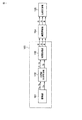
図1は、本発明の一実施形態に係る画像処理装置を含む全体構成を示す機能ブロック図である。同図に示す如く画像処理装置100は、撮像部101、G補間色差算出部102、補間処理部103からなる。
Hereinafter, an embodiment of the present invention will be described with reference to the drawings.
FIG. 1 is a functional block diagram showing an overall configuration including an image processing apparatus according to an embodiment of the present invention. As shown in FIG. 1, the
撮像部101は、図示しない光学系のレンズ、Ir(赤外線)カットフィルタ、光学ローパスフィルタ、R,G,Bのカラーフィルタを備えた単板のCCD(Charge Coupled Device:電荷結合素子)やCMOSイメージセンサ等の個体撮像デバイスでなる撮像素子、及び該撮像素子のコントローラからなり、該レンズ、Irカットフィルタ、光学ローパスフィルタを介して単板の撮像素子上に結像した光が、当該素子の各画素毎に形成されている所定色(RGB)フィルタを透過した後に各画素で光電変換される。
The
該光電変換された各画素の電気信号は増幅器にて増幅され、A/D変換されて、この撮像部101より色信号Rs,Gs,BsとしてG補間色差算出部102へ出力される。このとき、前記撮像部101内のコントローラは、色信号Rs,Bsと色信号Gsとをそれぞれ分けてG補間色差算出部102に出力する。
The photoelectrically converted electrical signal of each pixel is amplified by an amplifier, A / D converted, and output from the
さらに前記コントローラは、各色信号Rs,Bsと色信号Gsに対するノイズ低減処理機能及びホワイトバランス処理機能等を備えており、G補間色差算出部102へ出力されるRs,BsとGsにはこれらの処理が施されている。
Further, the controller has a noise reduction processing function and a white balance processing function for the color signals Rs and Bs and the color signal Gs, and the Rs, Bs and Gs output to the G interpolation color
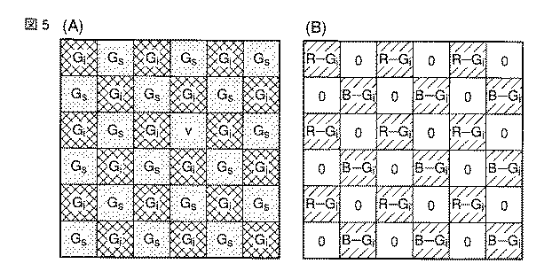
G補間色差算出部102は、入力された色信号Rs,Bsの画素位置に対応する補間G画素であるGiと該画素位置での色差信号R−Gi,B−Giを算出し、色差信号R−Gi,B−Giについては図5(B)にあるような2次元配列に従ってラスタスキャン順で補間処理部103へ出力する一方で、G信号についても図5(A)にあるような2次元配列にしたがってラスタスキャン順に補間処理部103へ出力する。
The G interpolation color
補間処理部103は、前記図5(B)に配置されていない欠落した色差信号R−G、B−Gをそれぞれ周辺の同一色差信号R−Gi、あるいはB−Giを用いて補間し、全画素位置での色差信号R−GとB−Gをそれぞれ画質調整部104へ出力する。一方で補間処理部103は、色信号Gについても同様に前記図5(A)に配置した周辺のGs,Giを用いて補間し、画質調整部104へ出力する。
The
こうして画質調整部104には、前記補間処理部103で算出した各画素位置のR,G,B信号が入力される。
In this way, the image
図4に画質調整部104のより詳細な回路構成を示す。同図で、画質調整部104に入力されたR,G,B信号は、カラーマトリックス処理部401に入力され、例えばsRGB等の所定色空間に変換される。
FIG. 4 shows a more detailed circuit configuration of the image
カラーマトリックス処理部401の出力する変換後のR,G,B信号は、例えば各12ビットの階調信号がγ補正部402,403,404にてそれぞれγ補正され、8ビットの信号に変換されたRγ、Gγ、Bγ信号として、画質調整部104の次段の圧縮記録部105に出力される。
For the converted R, G, B signals output from the color
圧縮記録部105では、γ補正された信号R,G,Bを画像圧縮し、記録媒体を構成するフラッシュメモリやハードディスク装置、あるいは磁気テープ等に記録する。
The
次いで図2により前記G補間色差算出部102の詳細な回路構成について説明する。
図2において、前記撮像部101から出力された色信号Rs、Bsはメモリ201に、色信号Gsはメモリ202に、それぞれ欠落G画素位置の2次元的な補間処理が実施可能となる画素分が揃うまでの遅延を得るために所定ライン分が格納される。この図2の例では、メモリ201,202に格納されるライン数は最低3ラインである。
Next, a detailed circuit configuration of the G interpolation color
In FIG. 2, the color signals Rs and Bs output from the
欠落G画素の位置にはR画素あるいはB画素が配置されているが、これら2つの色信号をX、あるいはX画素と記すものとして以下に説明する。 An R pixel or a B pixel is arranged at the position of the missing G pixel. The following description will be made assuming that these two color signals are denoted as X or X pixel.
欠落G画素の補間方法としては前記図15(A)〜図15(C)でも示した3種類のG画素の配置を使用する。それぞれの補間式は
Gv=(G1+G2)/2、
Gh=(G3+G4)/2、
Ga=(G1+G2+G3+G4)/4
となる。これらの各補間値は縦補間G算出部203、横補間G算出部204、4画素補間G算出部205にて算出された後に、減算部207,208,209に入力される。
As a method for interpolating missing G pixels, the arrangement of the three types of G pixels shown in FIGS. 15A to 15C is used. Each interpolation formula is
Gv = (G1 + G2) / 2,
Gh = (G3 + G4) / 2,
Ga = (G1 + G2 + G3 + G4) / 4
It becomes. These interpolation values are calculated by the vertical interpolation
前記メモリ201に格納されている欠落G画素と同一位置にあるX画素が、減算部207,208に入力され、さらにローパスフィルタ206を介して高周波成分が除去されたXL画素として減算部209に入力される。
The X pixel located at the same position as the missing G pixel stored in the
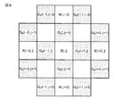
ここでローパスフィルタ206は、例えば図6に示すように処理対象となっている欠落G画素とその上下左右に位置する同種X画素の計5画素、すなわち
X(i,j),X(i,j+2),X(i,j-2),X(i-2,j),X(i+2,j)
により算出され、前記ローパスフィルタは以下の式
XL(i,j)=αX(i,j)
+β(X(i,j+2)+X(i,j-2)
+X(i-2,j)+X(i+2,j))
(但し、α,β:欠落G画素の周辺4画素平均で算出したGaの斜め45度方向の空間周波数特性に近似させる重み値。)
に従ってフィルタリング処理を実行する。
Here, the low-
X (i, j), X (i, j + 2), X (i, j-2), X (i-2, j), X (i + 2, j)
The low-pass filter is calculated by the following equation:
XL (i, j) = αX (i, j)
+ Β (X (i, j + 2) + X (i, j-2)
+ X (i-2, j) + X (i + 2, j))
(However, α, β are weight values approximated to the spatial frequency characteristics of Ga in a 45-degree oblique direction calculated by averaging four pixels around the missing G pixel.)
The filtering process is executed according to.
減算部207,208,209が算出する色差信号X−Gv、X−Gh、XL−Gaを、それぞれメモリ210,211,212が格納する。
The color difference signals X-Gv, X-Gh, and XL-Ga calculated by the
メモリ210,211,212は、それぞれ該色差信号に対し、図7(A)〜図7(C)に示す色差信号が3行3列分含まれる近傍領域で類似度算出処理を実施するための遅延を得るべく設ける。本実施形態では、メモリ210,211,212が格納するライン数は最小で5ラインとなる。
The
メモリ210,211,212に色差の周辺類似度算出処理ができるだけの色差信号が格納された時点で、これらメモリ210,211,212からそれぞれの所定色差信号X−Gv、X−Gh、XL−Gaを周辺類似度算出部213,214,215に出力する。
When the color difference signals that can perform the color difference peripheral similarity calculation processing are stored in the
周辺類似度算出部213は、欠落G画素位置(k,l)での色差周辺類似度Sv(k,l)を前記図7(A)に示したように中央の色差信号(X−Gv)k, lとその周辺位置の8つの色差
(X−Gv)k-2, l-2、(X−Gv)k, l-2、
(X−Gv)k+2, l-2、(X−Gv)k-2, l、
(X−Gv)k+2, l、(X−Gv)k-2, l+2、
(X−Gv)k, l+2、(X−Gv)k+2, l+2
を使用したSv1(k, l)と、
(X-Gv) k-2, l-2 , (X-Gv) k, l-2 ,
(X-Gv) k + 2, l-2 , (X-Gv) k-2, l ,
(X-Gv) k + 2, l , (X-Gv) k-2, l + 2 ,
(X-Gv) k, l + 2 , (X-Gv) k + 2, l + 2
Sv1 (k, l) using
同様に周辺類似度算出部214は、欠落G画素位置(k,l)での色差周辺類似度Sh(k,l)を前記図7(B)に示したように中央の色差信号(X−Gh)k, lとその周辺位置の8つの色差
(X−Gh)k-2, l-2、(X−Gh)k, l-2、
(X−Gh)k+2, l-2、(X−Gh)k-2, l、
(X−Gh)k+2, l、(X−Gh)k-2, l+2、
(X−Gh)k, l+2、(X−Gh)k+2, l+2
を使用したSh1(k, l)と、
(X-Gh) k-2, l-2 , (X-Gh) k, l-2 ,
(X-Gh) k + 2, l-2 , (X-Gh) k-2, l ,
(X-Gh) k + 2, l , (X-Gh) k-2, l + 2 ,
(X-Gh) k, l + 2 , (X-Gh) k + 2, l + 2
Sh1 (k, l) using
さらに周辺類似度算出部215は、欠落G画素位置(k,l)での色差周辺類似度Sa(k,l)を前記図7(C)に示したように中央の色差信号(XL−Ga)k, lとその周辺位置の8つの色差
(XL−Ga)k-2, l-2、(XL−Ga)k, l-2、
(XL−Ga)k+2, l-2、(XL−Ga)k-2, l、
(XL−Ga)k+2, l、(XL−Ga)k-2, l+2、
(XL−Ga)k, l+2、(XL−Ga)k+2, l+2
を使用したSa1(k, l)と、
(X L -Ga) k-2 , l-2, (X L -Ga) k, l-2,
(X L -Ga) k + 2 , l-2, (X L -Ga) k-2, l,
(X L -Ga) k + 2 , l, (X L -Ga) k-2, l + 2,
(X L -Ga) k, l + 2, (X L -Ga)
Sa1 (k, l) using
算出された3つの色差周辺類似度Sv(k,l),Sh(k,l),Sa(k,l)は判定部216に入力される。
この判定部216には、前記3つの色差周辺類似度Sv(k,l),Sh(k,l),Sa(k,l)が最小となる1つを選択し、選択した色差周辺類似度に対応する方向を示す選択信号を色差選択部217と高色差判定部219に入力する。このように、判定部216で色差周辺類似度Sv(k,l),Sh(k,l),Sa(k,l)が最小となる1つを選択することで、いずれの方向にエッジが生じているかを判断する。
The calculated three color difference peripheral similarity Sv (k, l), Sh (k, l), and Sa (k, l) are input to the determination unit 216.
The determination unit 216 selects one of the three color difference peripheral similarities Sv (k, l), Sh (k, l), and Sa (k, l), and selects the selected color difference peripheral similarity. A selection signal indicating a direction corresponding to is input to the color
色差選択部217には、前記メモリ210,211,212から欠落G画素位置(k,l)に対応する色差候補(X−Gv)k,l、(X−Gh)k,l、(XL−Ga)k,lが入力されており、前記判定部216から入力される選択信号に対応する1つの色差を選択して出力する。
The color
具体的には、色差周辺類似度Sv(k,l)が最小となると、(X−Gv)k,lが出力される。同様にSh(k,l)が最小となると(X−Gh)k,lが出力され、Sa(k,l)が最小となると(XL−Ga)k,lが出力される。 Specifically, when the color difference peripheral similarity Sv (k, l) is minimized, (X−Gv) k, l is output. Similarly, (X−G h ) k, l is output when Sh (k, l) is minimized, and (XL−Ga) k, l is output when Sa (k, l) is minimized.
この色差信号は、前記図5(B)に示したような2次元配列を左上から右下へ走査するラスタスキャン順で色差補間処理部103に出力される。補間処理部103は、R−GiとB−Giに分け、それぞれに欠落している色差信号の画素位置について周辺のR−Gi、あるいはB−Giを用いて補間する。
This color difference signal is output to the color difference
さらに前記メモリ218は、撮像画素として存在するX画素値の一時退避用として設けられ、前記色差信号X−Gv,X−Gh,XL−Gaのいずれか1つを選択、出力するタイミングにあわせるためのものであり、その保持内容を減算部220に読出す。
Further, the
減算部220は、同一画素位置の色差X−Gv,X−Gh,XL−Gaのいずれか1つとXとで以下の減算処理を行ない、欠落G画素位置のGi信号を算出する。すなわち、
色差X−Gvを選択した場合:Gi=X−(X−Gv)
色差X−Ghを選択した場合:Gi=X−(X−Gh)
色差XL−Gaを選択した場合:Gi=X−(XL−Ga)
さらに高色差判定部219にはメモリ212に格納されている色差(XL−Ga)が入力され、高色差判定部219は予め決定されている所定閾値THc(例えば最大階調値/10程度の値)と比較する。
The
When color difference X-Gv is selected: Gi = X- (X-Gv)
When color difference X-Gh is selected: Gi = X- (X-Gh)
When color difference XL-Ga is selected: Gi = X- (XL-Ga)
Further, the color difference (XL-Ga) stored in the
比較の結果、色差(XL−Ga)>THcとなり、さらに判定部216からの出力である選択信号が色差(XL−Ga)に対応する方向を選択した場合に、高色差判定部219はG補間を変更するための変更要求信号として「非高色差:00」または「高色差:01」をエッジ判定部221に出力する。高色差判定部219は、色差(XL−Ga)>THcのときに「高色差:01」を出力し、色差(XL−Ga)≦THcのときに「非高色差:00」を出力する。
As a result of the comparison, when the color difference (XL-Ga)> THc is satisfied and the selection signal output from the determination unit 216 selects a direction corresponding to the color difference (XL-Ga), the high color
エッジ判定部221は、高色差判定部219からの変更要求信号が「非高色差:00」の場合、その変更要求信号をそのままG補間選択部227に出力する。
If the change request signal from the high color
一方でエッジ判定部221は、高色差判定部219からの要求信号が「高色差:01」の場合、後述する、斜45度G算出部225から入力される斜め45度エッジ補間値s45と、斜135度G算出部226から入力される斜め135度エッジ補間値s135とを比較して、エッジが存在するかを判定する。例えば、斜め45度エッジ補間値s45と斜め135度エッジ補間値s135の差を所定の閾値EdgeTH(例えば最大階調値/16程度の値)と比較し、
|s45−s135|>EdgeTH
となるような場合にエッジがあると判定する。また、
|s45−s135|≦EdgeTH
となるような場合にはエッジがない(平坦部)と判定する。
On the other hand, when the request signal from the high color
| S45-s135 |> EdgeTH
In such a case, it is determined that there is an edge. Also,
| S45-s135 | ≦ EdgeTH
In such a case, it is determined that there is no edge (flat portion).
エッジが存在した場合、エッジ判定部221はさらにいずれの方向にエッジが存在するかを判定する。例えば、減算部220からの出力Giと斜め45度エッジ補間値s45の差と減算部220からの出力Giと斜め135度エッジ補間値s135の差を比較し、
|Gi−s45|<|Gi−s135|
となるような場合に45度方向にエッジがあると判別する。また、
|Gi−s45|≧|Gi−s135|
となるような場合には135度方向にエッジがあると判別する。
When there is an edge, the
| Gi-s45 | <| Gi-s135 |
In such a case, it is determined that there is an edge in the 45 degree direction. Also,
| Gi-s45 | ≧ | Gi-s135 |
In such a case, it is determined that there is an edge in the direction of 135 degrees.
そして、その判定結果に伴って変更要求信号として「高色差且つ非エッジ:01」または「高色差且つ45度エッジ:10」または「高色差且つ135度エッジ:11」をG補間選択部227に出力する。
Then, according to the determination result, “high color difference and non-edge: 01” or “high color difference and 45 degree edge: 10” or “high color difference and 135 degree edge: 11” as a change request signal to the G
4画素平均G算出部223は、メモリ222に格納されているG信号から画素X(k,l)の上下左右に隣接する4画素分、G(k−1,l),G(k,l−1),G(k+1,l),G(k,l+1)の平均値を欠落G画素位置(k,l)の補間Gaとして作成し、G補間選択部227に出力する。
The four-pixel average
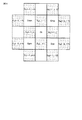
斜G補間算出部224は、前記メモリ222に格納されているG(Gi)信号から画素X(k,l)の斜めに位置するX(k−1,l−1),X(k−1,l+1),X(k+1,l−1),X(k+1,l+1)にそれぞれ上下左右に隣接するG画素値の平均値Gmm,Gmp,Gpm,Gppを算出し、斜45度G算出部225と斜135度G算出部226に出力する。図9に示すGmm,Gmp,Gpm,Gppは以下のようになる。すなわち、
Gmm=(G(i-1,j-2)+G(i,j-1)
+G(i-1,j-2)+G(i-1,j))/4
Gmp=(G(i,j-1)+G(i+2,j-1)
+G(i+1,j-2)+G(i+1,j))/4
Gpm=((i-2,j+1)+G(i,j+1)
+G(i-1,j)+G(i-1,j+2))/4
Gpp=(G(i,j+1)+G(i+2,j+1)
+G(i+1,j)+G(i+1,j+2))/4
斜45度G算出部225と斜135度G算出部226は、斜G補間算出部224から入力された画素X(k,l)の斜め位置にある前記G画素補間値Gmm,Gmp,Gpm,Gppと、減算部220にて算出されたG補間値Giとに基づいて、それぞれ斜め45度補間値s45と斜め135度補間値s135とを算出し、エッジ判定部221及びG補間選択部227へ出力する。
The oblique G
Gmm = (G (i-1, j-2) + G (i, j-1)
+ G (i-1, j-2) + G (i-1, j)) / 4
Gmp = (G (i, j-1) + G (i + 2, j-1)
+ G (i + 1, j-2) + G (i + 1, j)) / 4
Gpm = ((i-2, j + 1) + G (i, j + 1)
+ G (i-1, j) + G (i-1, j + 2)) / 4
Gpp = (G (i, j + 1) + G (i + 2, j + 1)
+ G (i + 1, j) + G (i + 1, j + 2)) / 4
The oblique 45 degree
この点を詳述すると、前記図9において
s45=((2*Gi)+Gmm+Gpp)/4
s135=((2*Gi)+Gmp+Gpm)/4
となる。
To elaborate on this point, in FIG.
s45 = ((2 * Gi) + Gmm + Gpp) / 4
s135 = ((2 * Gi) + Gmp + Gpm) / 4
It becomes.
G補間選択部227は、減算部220の出力である欠落G画素位置(k,l)のG信号補間値Gi、4画素平均G算出部223の出力である補間値Ga、斜45度G算出部225の出力である斜め45度補間値s45、及び斜135度G算出部226の出力である斜135度補間値s135と、エッジ判定部221からの変更要求信号を入力し、該変更要求信号の内容に応じた選択を行なって、選択結果を次段の補間処理部103へ出力する。
The G
すなわち、変更要求信号が「非高色差:00」の場合は、減算部220にて算出したG補間値Giを選択する。変更要求信号が「高色差且つ非エッジ:01」の場合には、4画素平均G算出部223の出力であるGaを選択する。変更要求が「高色差且つ45度エッジ:10」の場合には、斜45度G算出部225の出力であるs45を選択する。そして、変更要求が「高色差且つ135度エッジ:11」の場合には、斜135度G算出部226の出力であるs135を選択する。
That is, when the change request signal is “non-high color difference: 00”, the G interpolation value Gi calculated by the
次に図3を用いて補間処理部103の詳細について説明する。
補間処理部103には、前段のG補間色差算出部102から出力される前記図5(A)の2次元配列構造を持ったG信号と、図5(B)の2次元配列構造を持った色差X−Gi信号とが入力される。
Next, details of the
The
G補間色差算出処理部102から出力されるこの色差X−Gi信号は、補間処理部103内にてまず色差選別部301に入力される。この色差選別部301は、色差X−Gi信号を色差R−Gi信号と色差B−Gi信号とに分離してメモリ302,303に格納させる。
The color difference X-Gi signal output from the G interpolation color difference
メモリ302,303に格納される色差R−Gi信号と色差B−Gi信号は、それぞれ所定位置への補間処理に必要なライン数分が格納され、補間処理が開始可能となった時点でその補間処理に必要な画素が補間算出部304,305に読出される。
The color difference R-Gi signal and the color difference B-Gi signal stored in the
補間算出部304,305では、制御部310から送られてくる補間フィルタ係数に基づいて補間画素である色差R−G信号及び色差B−G信号を算出して出力する。
The
一方、前段のG補間色差算出部102からのG信号はメモリ306に格納される。このメモリ306に格納されるG信号は、それぞれ所定位置への補間処理に必要なライン数分が格納され、補間処理が開始可能となった時点でその補間処理に必要な画素が補間算出部307に読出される。
On the other hand, the G signal from the preceding G interpolation color
この補間算出部307では、制御部310から送られてくる補間フィルタ係数により基づいて補間画素であるG信号を算出して出力する。
The
前記補間算出部304,305,307での補間算出処理は、例えば図8に示す8×8画素の領域に対するもので、撮像素子と同一解像度の画像サイズを指定した場合の例として水平、垂直各方向共に1/2画素位置に画素を作成するものである。
The interpolation calculation processing in the
補間算出処理で使用する補間フィルタの例としては、Lanczosフィルタ等の畳み込みフィルタを使用するものとし、水平方向に処理した1次元フィルタリングの結果に垂直方向の1次元フィルタリングを施すことで補間画素を算出する。 As an example of the interpolation filter used in the interpolation calculation process, a convolution filter such as a Lanczos filter is used, and the interpolation pixel is calculated by performing vertical one-dimensional filtering on the result of the one-dimensional filtering processed in the horizontal direction. To do.
これら1次元のフィルタリングは2次元フィルタリングとすることも可能であり、例えば図10に8×8タップの2次元フィルタの例を示す。図10(A)は、G信号に対するフィルタである。 These one-dimensional filtering may be two-dimensional filtering. For example, FIG. 10 shows an example of a two-dimensional filter of 8 × 8 taps. FIG. 10A shows a filter for the G signal.
また、図10(B)〜図10(E)は色差R−Gi信号と色差B−Gi信号に対するフィルタであり、補間画素位置と処理対象の色差R−GiあるいはB−Giの位置関係により、これら4つのフィルタを制御部310にて適宜切換えて処理する。 10B to 10E are filters for the color difference R-Gi signal and the color difference B-Gi signal. Depending on the positional relationship between the interpolation pixel position and the color difference R-Gi or B-Gi to be processed, These four filters are appropriately switched by the control unit 310 for processing.
ここでG信号に対する補間フィルタ係数fijと色差に対する補間フィルタ係数fijとは同一係数fij=fijでも良いし、色差に対してより帯域制限をかけた異なるフィルタ係数fij≠fijとしても良い。 Here, the interpolation filter coefficient fij for the G signal and the interpolation filter coefficient fij for the color difference may be the same coefficient fij = fij, or may be different filter coefficients fij ≠ fij in which band limitation is further applied to the color difference.
また補間フィルタのタップ数を8×8タップとしたが、ハードウェアの規模とフィルタ特性の設計自由度とのトレードオフにより、N×Nタップ(ここでNは4の倍数)としても良い。なお、当然ながらG信号と色差R−Gi信号と色差B−Gi信号とで異なるタップ数としても良いのは言うまでもなく、この場合、G信号に対してはNが2の倍数のタップ数のフィルタを用いても良い。 The number of taps of the interpolation filter is 8 × 8 taps, but may be N × N taps (where N is a multiple of 4) depending on the trade-off between the hardware scale and the degree of freedom in designing the filter characteristics. Needless to say, the G signal, the color difference R-Gi signal, and the color difference B-Gi signal may have different tap numbers. In this case, for the G signal, a filter having a tap number in which N is a multiple of two. May be used.
上述のG補間色差算出部102及び補間処理部103の処理は、ハードウェア回路により実現するものとして説明したが、同じ機能を所謂、画像エンジンと称されるDSP(Digital Signal Processor)を用いてソフトウェア処理により実現することも容易に可能である。
The processing of the G interpolation color
以下に、ソフトウェア処理によりG補間色差算出部102の機能を実現する場合の具体的な手順を図11、図12のフローチャートに基づいて説明する。
A specific procedure for realizing the function of the G interpolation color
まず、撮像部101で撮像された後、メモリに格納されているカラー画像信号が、ラスタスキャン順にG補間色差算出部102に入力され、メモリ201,202に所定データ分が格納されている状態で、欠落G信号の補間候補値と色差候補値をメモリに格納するライン数×ライン画素数=N画素数を初期値、例えば本実施形態ではライン数=5、にセットする。(ステップS2000)
次いで、G信号欠落位置(i,j)に対して上下隣接G信号の平均値Gv(i,j)を算出し、G信号欠落位置(i,j)にあるX(i,j)(XはRまたはB)と前記補間候補Gv(i,j)に基づいて色差(X−Gv)i,jを算出してメモリに格納する。(ステップS2001)
続いてG信号欠落位置(i,j)に対して左右隣接G信号の平均値Gh(i,j)を算出し、G信号欠落位置(i,j)にあるX(i,j)(XはRまたB)と前記補間候補Gh(i,j)に基づいて色差(X−Gh)i,jを算出してメモリに格納する。(ステップS2002)
さらにG信号欠落位置(i,j)に対して上下左右隣接G信号の平均値Ga(i,j)を算出し、G信号欠落位置(i,j)にあるX(i,j)(XはRまたはB)とその周辺上下左右のX(i−2,j),X(i+2,j),X(i,j−2),X(i,j+2)とを用いて、斜め45度方向の周波数特性を該平均値Ga(i,j)算出時の補間フィルタの特性に近似させる帯域制限処理(ローパスフィルタ)を実施し、算出したXL(i,j)と該補間候補Ga(i,j)に基づいて色差(XL−Ga)i,jを算出してメモリに格納する。(ステップS2003)
この時点でN画素分の処理が終了したかを判定する。(ステップ2004)
N画素分の処理が終了していなければ前記ステップS2001に戻り、(X−Gv)i,j、(X−Gh)i,j、(XL−Ga)i,jを算出してメモリに格納する動作を続行する。
First, after the image is picked up by the
Next, the average value Gv (i, j) of the upper and lower adjacent G signals is calculated for the G signal missing position (i, j), and X (i, j) (X R or B) and the color difference (X−Gv) i, j are calculated based on the interpolation candidate Gv (i, j) and stored in the memory. (Step S2001)
Subsequently, the average value Gh (i, j) of the right and left adjacent G signals is calculated for the G signal missing position (i, j), and X (i, j) (X Calculates the color difference (X−Gh) i, j based on R or B) and the interpolation candidate Gh (i, j) and stores it in the memory. (Step S2002)
Further, the average value Ga (i, j) of the G signal missing position (i, j) is calculated for the G signal missing position (i, j), and X (i, j) (X R or B) and X (i−2, j), X (i + 2, j), X (i, j−2), X (i, j + 2) around the top, bottom, left, and right of the surrounding area, 45 degrees diagonally A band limiting process (low-pass filter) for approximating the frequency characteristic of the direction to the characteristic of the interpolation filter at the time of calculating the average value Ga (i, j) is performed, and the calculated XL (i, j) and the interpolation candidate Ga (i , J), the color difference (XL-Ga) i, j is calculated and stored in the memory. (Step S2003)
At this time, it is determined whether the processing for N pixels is completed. (Step 2004)
If the processing for N pixels is not completed, the process returns to step S2001, and (X-Gv) i, j, (X-Gh) i, j, (XL-Ga) i, j are calculated and stored in the memory. To continue the operation.
一方、前記ステップS2004でN画素分の処理が終了したと判定された時点で、Nを1にセットする。(ステップS2005)
そして、前記ステップS2001からステップS2004の処理ループにおいてメモリに格納したG信号欠落位置(k,l)の同一補間種で算出された色差(X−Gv)k,lとその近傍8方向の同種色差
(X−Gv)k+n,l+m
(但し、n:−2,0,2、
m: −2,0,2。)
とに基づいて周辺類似度Sv1(k,l)を算出する。
On the other hand, N is set to 1 when it is determined in step S2004 that the processing for N pixels has been completed. (Step S2005)
Then, the color difference (X−Gv) k, l calculated with the same interpolation type at the G signal missing position (k, l) stored in the memory in the processing loop from step S2001 to step S2004 and the same kind of color difference in the
(X-Gv) k + n, l + m
(However, n: -2, 0, 2,
m: -2, 0, 2. )
Based on the above, the peripheral similarity Sv1 (k, l) is calculated.
一方で、色差(X−Gv)k,lの周辺異種色差
(X−Gv)k+n,l+m
(但し、n:−1,1、
m:−1,1。)
に基づいて周辺類似度Sv2(k,l)を算出する。
On the other hand, different color difference around color difference (X-Gv) k, l
(X-Gv) k + n, l + m
(However, n: -1,1,
m: -1,1. )
Based on the above, the peripheral similarity Sv2 (k, l) is calculated.
これら2つの周辺類似度Sv1(k,l)とSv2(k,l)を加算して周辺類似度Sv(k,l)を算出する。(ステップS2007)
続いて、同様にメモリに格納されているG信号欠落位置(k,l)の同一補間種で算出された色差(X−Gh)k,lとその近傍8方向の同種色差
(X−Gh)k+n,l+m
(但し、n:−2,0,2、
m:−2,0,2。)
とに基づいて周辺類似度Sh1(k,l)を算出する。
These two peripheral similarities Sv1 (k, l) and Sv2 (k, l) are added to calculate the peripheral similarity Sv (k, l). (Step S2007)
Subsequently, similarly, the color difference (X−Gh) k, l calculated with the same interpolation type at the G signal missing position (k, l) stored in the memory and the same type of color difference in the
(X-Gh) k + n, l + m
(However, n: -2, 0, 2,
m: -2, 0, 2. )
Based on the above, the peripheral similarity Sh1 (k, l) is calculated.
一方で、色差(X−Gh)k,lの周辺異種色差
(X−Gh)k+n,l+m
(但し、n:−1,1、
m:−1,1。)
に基づいて周辺類似度Sh2(k,l)を算出する。
On the other hand, different color difference around color difference (X-Gh) k, l
(X-Gh) k + n, l + m
(However, n: -1,1,
m: -1,1. )
Based on the above, the peripheral similarity Sh2 (k, l) is calculated.
これら2つの周辺類似度Sh1(k,l)とSh2(k,l)を加算して周辺類似度Sh(k,l)を算出する。(ステップS2008)
同様に、メモリに格納されているG信号欠落位置(k,l)の同一補間種で算出された色差(XL−Ga)k,lとその近傍8方向の同種色差
(XL−Ga)k+n,l+m
(但し、n:−2,0,2、
m:−2,0,2。)
とに基づいて周辺類似度Sa1(k,l)を算出する。
These two peripheral similarities Sh1 (k, l) and Sh2 (k, l) are added to calculate the peripheral similarity Sh (k, l). (Step S2008)
Similarly, the color difference (XL-Ga) k, l calculated with the same interpolation type at the G signal missing position (k, l) stored in the memory and the same type of color difference in the eight directions in the vicinity thereof.
(XL-Ga) k + n, l + m
(However, n: -2, 0, 2,
m: -2, 0, 2. )
Based on the above, the peripheral similarity Sa1 (k, l) is calculated.
一方で、色差(XL−Ga)k,lの周辺異種色差
(XL−Ga)k+n,l+m
(但し、n:−1,1、
m:−1,1。)
に基づいて周辺類似度Sa2(k,l)を算出する。
On the other hand, the different color difference around the color difference (XL-Ga) k, l
(XL-Ga) k + n, l + m
(However, n: -1,1,
m: -1,1. )
Based on the above, the peripheral similarity Sa2 (k, l) is calculated.
これら2つの周辺類似度Sa1(k,l)とSa2(k,l)を加算して周辺類似度Sa(k,l)を算出する。(ステップS2009)
ここで周辺類似度Sv(k,l),Sh(k,l),Sa(k,l)はいずれも、値が小さい程、類似性が高くなる量であり、続いて類似性が最大、換言すれば類似度の値としては最小となる1つの色差選択を行なう。
These two peripheral similarities Sa1 (k, l) and Sa2 (k, l) are added to calculate the peripheral similarity Sa (k, l). (Step S2009)
Here, the peripheral similarity Sv (k, l), Sh (k, l), and Sa (k, l) are all the amounts that the similarity becomes higher as the value is smaller. In other words, one color difference selection that minimizes the similarity value is performed.
すなわち、前記3つの周辺類似度Sv(k,l),Sh(k,l),Sa(k,l)が算出された時点で、周辺類似度Sv(k,l)とSh(k,l)を比較する。(ステップS2010)
ここでSv(k,l)の方が小さい場合は、さらにSv(k,l)とSa(k,l)とを比較する。(ステップS2012)。
That is, when the three peripheral similarities Sv (k, l), Sh (k, l), and Sa (k, l) are calculated, the peripheral similarities Sv (k, l) and Sh (k, l) ). (Step S2010)
Here, when Sv (k, l) is smaller, Sv (k, l) is further compared with Sa (k, l). (Step S2012).
比較の結果、Sv(k,l)が小さいと判定した場合はステップ2013に進む。また、前記ステップS2012でSv(k,l)が大きいと判定するか、あるいはSv(k,l)とSa(k,l)が等しいと判定した場合はステップ2014に進む。 As a result of the comparison, if it is determined that Sv (k, l) is small, the process proceeds to step 2013. If it is determined in step S2012 that Sv (k, l) is large, or if it is determined that Sv (k, l) and Sa (k, l) are equal, the process proceeds to step 2014.
また、前記ステップS2010で周辺類似度Sv(k,l)とSh(k,l)の比較でSv(k,l)が大きいか、Sv(k,l)とSh(k,l)が等しいと判定した場合は、次にSh(k,l)とSa(k,l)とを比較する(ステップS2011)。 In step S2010, Sv (k, l) is large or Sv (k, l) and Sh (k, l) are equal in comparison between the peripheral similarity Sv (k, l) and Sh (k, l). Then, Sh (k, l) is compared with Sa (k, l) (step S2011).
ここで、Sh(k,l)が小さいと判定した場合はステップS2015に、Sh(k,l)が大きいか、またはSh(k,l)とSa(k,l)が等しいと判定した場合はステップS2014に進む。 If it is determined that Sh (k, l) is small, it is determined in step S2015 that Sh (k, l) is large or Sh (k, l) and Sa (k, l) are equal. Advances to step S2014.
ステップS2013では、G信号欠落位置(k,l)の色差(k,l)を(X−Gv)k,lに決定してメモリに格納する。 In step S2013, the color difference (k, l) at the G signal missing position (k, l) is determined as (X−Gv) k, l and stored in the memory.
ステップS2014では、G信号欠落位置(k,l)の色差(k,l)を(XL−Ga)k,lに決定してメモリに格納する。 In step S2014, the color difference (k, l) at the G signal missing position (k, l) is determined as (XL-Ga) k, l and stored in the memory.
ステップS2015では、G信号欠落位置(k,l)の色差(k,l)を(X−Gh)k,lに決定してメモリに格納する。 In step S2015, the color difference (k, l) of the G signal missing position (k, l) is determined as (X−Gh) k, l and stored in the memory.
前記ステップS2013〜S2015いずれかのメモリ格納処理後、G信号欠落位置(k,l)で決定された色差(k,l)をX(k,l)から減算することでG(k,l)を算出してメモリに格納する。(ステップS2016)
その後、さらに高色差領域処理(ステップS2017)を行なうが、これは図12のサブルーチンのフローチャートに基付いて後述する。
After the memory storing process in any one of steps S2013 to S2015, the color difference (k, l) determined at the G signal missing position (k, l) is subtracted from X (k, l) to obtain G (k, l). Is calculated and stored in the memory. (Step S2016)
Thereafter, further high color difference area processing (step S2017) is performed, which will be described later based on the flowchart of the subroutine of FIG.
高色差領域処理後、出力画像としての総画素数分の処理を終了したかを判定する。(ステップS2018)。総画素数分の処理が終了していないと判定すると、再び前記ステップS2001からの処理に戻り、メモリに格納されている不必要となった(X−Gv),(X−Gh),(XL−Ga),Sv,Sh,Saを新しく算出される値で置換しながら前述した一連の処理を継続する。 After the high color difference area processing, it is determined whether the processing for the total number of pixels as the output image has been completed. (Step S2018). If it is determined that the processing for the total number of pixels has not been completed, the processing returns to the processing from step S2001 again, and is unnecessary (X-Gv), (X-Gh), (XL) stored in the memory. -Ga), Sv, Sh, Sa are replaced with newly calculated values, and the above-described series of processing is continued.
しかして、総画素数分の処理を全て終了した時点で、前記ステップS2018によりその状態を判定し、以上で図11のG補間色差算出処理を終了する。 Thus, when all the processes for the total number of pixels are completed, the state is determined in step S2018, and the G interpolation color difference calculation process of FIG.
続いて図12により前記高色差領域処理の詳細な処理内容を示す。
図12は、高色差領域処理のサブルーチンを示すフローチャートである。その当初、G信号欠落位置(k,l)の周辺4画素G(k−1,l)、G(k+1,l)、G(k,l−1)、G(k,l+1)の平均値Gaを算出する。(ステップS3000)
その算出結果によりG信号欠落位置(k,l)で決定された色差(k,l)が(XL−Ga)k,lであり、且つその値がしきい値THcより大きいか否かを判定する。(ステップS3001)。
Next, FIG. 12 shows the detailed processing contents of the high color difference area processing.
FIG. 12 is a flowchart showing a subroutine of high color difference area processing. Initially, the average value of the surrounding four pixels G (k−1, l), G (k + 1, l), G (k, l−1), G (k, l + 1) around the G signal missing position (k, l) Ga is calculated. (Step S3000)
Based on the calculation result, it is determined whether the color difference (k, l) determined at the G signal missing position (k, l) is (XL−Ga) k, l and the value is larger than the threshold value THc. To do. (Step S3001).
ここで色差(k,l)が(XL−Ga)k,lであり、且つその値がしきい値THcより大きいと判定した場合には、次いでG信号欠落位置の斜め4位置に上下左右隣接Gの平均値Gmm,Gmp,Gpm,Gppを算出する。(ステップS3002)
このとき、直前の前記ステップS2016で算出したG(k,l)と前記ステップS3002で算出したGmm,Gmp,Gpm,Gppとから45度方向平均値s45と、135度方向平均値s135とを算出する。(ステップS3003)
このステップS3003で算出した45度方向平均値s45と135度方向平均値s135とを使用して平坦であるか否か判定を行なう。(ステップS3004)
ここで平坦であると判定した場合は、G(k,l)を周辺4画素平均値Gaに置換する。(ステップS3005)
一方、前記ステップS3004で平坦ではないと判定した場合には、ついで45度方向平均値s45、及び135度方向平均値s135と直前の前記ステップS2016で算出したG(k,l)を使用してエッジ方向を判定する。(ステップS3006)
ここでエッジ方向が45度であると判定した場合は、信号G(k,l)を45度方向平均値s45に置換する。(ステップS3008)
一方、前記ステップS3006でエッジ方向が45度ではないと判定した場合は、G(k,l)を135度方向平均値s135に置換する。(ステップS3007)
前記ステップS3005,S3007,S3008いずれかの処理の実行によりこの図12のサブルーチンを終え、前記図11のメインルーチンにリターンする。
Here, when it is determined that the color difference (k, l) is (XL-Ga) k, l and the value is larger than the threshold value THc, next, the upper and lower left and right adjacent to the four positions of the G signal missing position. Average values Gmm, Gmp, Gpm, and Gpp of G are calculated. (Step S3002)
At this time, the 45 degree direction average value s45 and the 135 degree direction average value s135 are calculated from G (k, l) calculated in the immediately preceding step S2016 and Gmm, Gmp, Gpm, and Gpp calculated in step S3002. To do. (Step S3003)
It is determined whether or not it is flat using the 45-degree direction average value s45 and the 135-degree direction average value s135 calculated in step S3003. (Step S3004)
If it is determined that the surface is flat, G (k, l) is replaced with the peripheral 4-pixel average value Ga. (Step S3005)
On the other hand, if it is determined in step S3004 that the surface is not flat, the 45 degree direction average value s45 and the 135 degree direction average value s135 and G (k, l) calculated in the immediately preceding step S2016 are used. Determine the edge direction. (Step S3006)
If it is determined that the edge direction is 45 degrees, the signal G (k, l) is replaced with a 45-degree direction average value s45. (Step S3008)
On the other hand, if it is determined in step S3006 that the edge direction is not 45 degrees, G (k, l) is replaced with a 135-degree direction average value s135. (Step S3007)
Execution of any one of the steps S3005, S3007, and S3008 completes the subroutine of FIG. 12, and returns to the main routine of FIG.
以上詳述した如く本実施形態によれば、入力時点ですでに周波数折返りなどの現象が生じているカラー撮像信号を処理した場合でも、水平及び垂直の各方向以外のエッジのある領域において入力信号を全方向に平滑化しないため、エッジにジャギーやアーティファクトなどの副作用を発生させることのないカラー画像を復元することができる。 As described above in detail, according to this embodiment, even when a color imaging signal in which a phenomenon such as frequency aliasing has already occurred is processed at the time of input, input is performed in a region having edges other than horizontal and vertical directions. Since the signal is not smoothed in all directions, it is possible to restore a color image that does not cause side effects such as jaggies and artifacts at the edges.
なお前記実施形態では、G補間色差算出部102にて、エッジ判定部221が斜45度G算出部225、斜135度G算出部226の出力により斜め方向に平滑化した複数の画素補間値の差から平坦度を判定するものとしたことで、より正確にエッジ判定を行なうことができる。
In the embodiment, in the G interpolation color
また前記実施形態では、G補間色差算出部102にて、エッジ判定部221が斜45度G算出部225、斜135度G算出部226の出力により斜め方向に平滑化した複数の画素補間値と、前記カラー撮像信号と前記高色差判定部219で算出した画素補間値との差を比較した比較結果により前記図12でも示した如く前記エッジの方向を判定するものとしたことで、より適切なエッジ判定を行なうことができる。
In the above-described embodiment, the G interpolation color
さらに前記実施形態では、補間処理部103にて、補間算出部307が前記エッジ判定部221で判定に用いた複数の斜め方向に平滑化した画素補間値のうちのいずれかを選択して最終結果に用いるものとしたので、カラー画像中からエッジにジャギーやアーティファクトなどの不具合を確実に除去することができる。
Furthermore, in the embodiment, the
なお前記実施形態では、色差類似度を使用して水平/垂直/それ以外とエッジの方向を判定しているが、例えば、水平及び垂直に並ぶG画素の差分をそれぞれ算出して比較し、垂直差分が水平差分よりも大きく場合は垂直方向のエッジ、水平差分が垂直差分よりも大きい場合は水平方向のエッジ、垂直平均値と水平平均値の差が小さい場合は水平及び垂直方向以外のエッジであると判定することも可能であり、さらにその判定基準とするのは色差類似度に限るものでもない。 In the above embodiment, the color difference similarity is used to determine the edge direction as horizontal / vertical / others. For example, the difference between the G pixels arranged in the horizontal and vertical directions is calculated and compared, and the vertical direction is determined. When the difference is greater than the horizontal difference, the edge in the vertical direction, when the horizontal difference is greater than the vertical difference, the edge in the horizontal direction, and when the difference between the vertical average value and the horizontal average value is small, the edge other than the horizontal and vertical directions It is also possible to determine that there is, and the determination criterion is not limited to the color difference similarity.
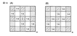
また前述した実施形態では、45度方向平均値s45及び135度方向平均値s135を算出するために、欠落G位置(k,l)の斜め4位置のGmm,Gmp,Gpm,Gppを算出するものとして説明したが、これらの算出方法を採らず、例えば図13(A)、図13(B)に示すような中心位置に重きを置いて各斜め方向の画素値を半減させるようなフィルタ処理を行なった結果を45度方向平均値s45、135度方向平均値s135として算出しても、全く同様の結果を得ることができることは言うまでもない。 In the above-described embodiment, in order to calculate the 45-degree direction average value s45 and the 135-degree direction average value s135, Gmm, Gmp, Gpm, and Gpp at four oblique positions of the missing G position (k, l) are calculated. However, these calculation methods are not adopted, and for example, a filter process that places a weight on the center position as shown in FIGS. 13A and 13B and halves the pixel value in each oblique direction. It goes without saying that the same result can be obtained even if the results obtained are calculated as the 45 degree direction average value s45 and the 135 degree direction average value s135.
その他、本発明は上述した実施形態に限定されるものではなく、実施段階ではその要旨を逸脱しない範囲で種々に変形することが可能である。また、上述した実施形態で実行される機能は可能な限り適宜組合わせて実施しても良い。上述した実施形態には種々の段階が含まれており、開示される複数の構成要件により適宜の組合せにより種々の発明が抽出され得る。例えば、実施形態に示される全構成要件からいくつかの構成要件が削除されても、効果が得られるのであれば、この構成要件が削除された構成が発明として抽出され得る。 In addition, the present invention is not limited to the above-described embodiments, and various modifications can be made without departing from the scope of the invention in the implementation stage. In addition, the functions executed in the above-described embodiments may be implemented in appropriate combination as much as possible. The above-described embodiment includes various stages, and various inventions can be extracted by an appropriate combination according to a plurality of disclosed structural requirements. For example, even if some constituent requirements are deleted from all the constituent requirements shown in the embodiment, if the effect is obtained, a configuration from which the constituent requirements are deleted can be extracted as an invention.
100…画像処理装置、101…撮像部、102…G補間色差算出部、103…補間処理部、104…画質調整部、105…圧縮記録部、201,202…メモリ、203…縦補間G算出部、204…横補間G算出部、205…4画素補間G算出部、206…ローパスフィルタ、210〜212…メモリ、213〜215…周辺類似度算出部、216…判定部、217…色差選択部、218…メモリ、219…高色差判定部、221…エッジ判定部、222…メモリ、223…4画素平均G算出部、224…斜G補間算出部、225…斜45度G算出部、226…斜135度G算出部、227…G補間選択部、301…色差選別部、302,303…メモリ、304,305…補間算出部、306…メモリ、307…補間算出部、310…制御部、313…メモリ、401…カラーマトリックス処理部、402〜404…γ補正部。
DESCRIPTION OF
Claims (6)
前記各撮像素子の画素値により前記カラー撮像信号中でエッジを生じている方向を判断する第1のエッジ方向判定手段と、
前記第1のエッジ方向判定手段でエッジ方向が特定の方向以外と判断した場合、画素値が所定以上の高色差となる領域を判定する高色差領域判定手段と、
前記高色差判定手段で高色差と判定した場合、さらにエッジの方向を判断する第2のエッジ方向判別手段と、
前記第2のエッジ方向判別手段で判断した方向に沿って各撮像素子の画素値を補間して平滑化する方向依存平滑化手段と、
前記第2のエッジ方向判別手段でいずれの方向にもエッジがないと判断した場合、各撮像素子の画素値を周囲の画素位置の画素値により全方向で平滑化する全方向平滑化手段と
を備えたことを特徴とする画像処理装置。 An imaging device that obtains a color imaging signal by arranging a plurality of types of imaging elements having different spectral sensitivities on a single surface;
First edge direction determination means for determining a direction in which an edge is generated in the color imaging signal based on a pixel value of each imaging element;
A high color difference region determination unit that determines a region having a high color difference with a pixel value equal to or greater than a predetermined value when the first edge direction determination unit determines that the edge direction is other than a specific direction;
A second edge direction discriminating means for further judging the edge direction when the high color difference judging means judges that the color difference is high;
Direction-dependent smoothing means for interpolating and smoothing the pixel values of each image sensor along the direction determined by the second edge direction determining means;
Omnidirectional smoothing means for smoothing the pixel values of each image sensor in all directions by the pixel values of surrounding pixel positions when the second edge direction determining means determines that there is no edge in any direction; An image processing apparatus comprising the image processing apparatus.
前記特定の方向とは異なる方向に平滑化した複数の画素補間値の差から平坦度を判定することで、いずれの方向にもエッジがないと判断することを特徴とする請求項1記載の画像処理装置。 The second edge direction determination means includes
The image according to claim 1, wherein it is determined that there is no edge in any direction by determining flatness from a difference between a plurality of pixel interpolation values smoothed in a direction different from the specific direction. Processing equipment.
前記特定の方向とは異なる方向に平滑化した複数の画素補間値と、前記カラー撮像信号と前記高色差から算出した画素補間値との差を比較した比較結果によりエッジの方向を判定することを特徴とする請求項1記載の画像処理装置。 The second edge direction determination means includes
Determining an edge direction based on a comparison result of a comparison between a plurality of pixel interpolation values smoothed in a direction different from the specific direction and a difference between the color imaging signal and a pixel interpolation value calculated from the high color difference. The image processing apparatus according to claim 1, wherein:
前記第2のエッジ方向判別手段で判定に用いた前記特定の方向とは異なる複数の方向に平滑化した画素補間値のうちのいずれかを選択して最終結果に用いる補間値選択手段を備えることを特徴とする請求項1記載の画像処理装置。 The direction-dependent smoothing means includes
Interpolation value selection means for selecting one of the pixel interpolation values smoothed in a plurality of directions different from the specific direction used for determination by the second edge direction determination means and using it as a final result is provided. The image processing apparatus according to claim 1.
前記第1のエッジ方向判定工程でエッジ方向が特定の方向以外と判断した場合、画素値が所定以上の高色差となる領域を判定する高色差領域判定工程と、
前記高色差判定工程で高色差と判定した場合、さらにエッジの方向を判断する第2のエッジ方向判別工程と、
前記第2のエッジ方向判別工程で判断した方向に沿って各撮像素子の画素値を補間して平滑化する方向依存平滑化工程と、
前記第2のエッジ方向判別工程でいずれの方向にもエッジがないと判断した場合、各撮像素子の画素値を周囲の画素位置の画素値により全方向で平滑化する全方向平滑化工程と
を有したことを特徴とする画像処理方法。 A plurality of types of imaging devices having different spectral sensitivities are arranged on a single plane, and the direction in which an edge is generated in the color imaging signal is determined based on the pixel value of each imaging device from an imaging device that obtains a color imaging signal. A first edge direction determination step;
A high color difference region determination step for determining a region having a high color difference with a pixel value equal to or greater than a predetermined value when the edge direction is determined to be other than a specific direction in the first edge direction determination step;
A second edge direction discriminating step for further judging the direction of the edge when the high color difference is judged in the high color difference judging step;
A direction-dependent smoothing step of interpolating and smoothing the pixel values of each image sensor along the direction determined in the second edge direction determining step;
An omnidirectional smoothing step of smoothing the pixel values of each image sensor in all directions by the pixel values of surrounding pixel positions when it is determined in the second edge direction determining step that there is no edge in any direction; An image processing method characterized by comprising:
前記各撮像素子の画素値により、前記カラー撮像信号中でエッジを生じている方向を判断する第1のエッジ方向判定ステップと、
前記第1のエッジ方向判定ステップでエッジ方向が特定の方向以外と判断した場合、画素値が所定以上の高色差となる領域を判定する高色差領域判定ステップと、
前記高色差判定ステップで高色差と判定した場合、さらにエッジの方向を判断する第2のエッジ方向判別ステップと、
前記第2のエッジ方向判別ステップで判断した方向に沿って各撮像素子の画素値を補間して平滑化する方向依存平滑化ステップと、
前記第2のエッジ方向判別ステップでいずれの方向にもエッジがないと判断した場合、各撮像素子の画素値を周囲の画素位置の画素値により全方向で平滑化する全方向平滑化ステップと
をコンピュータに実行させることを特徴とするプログラム。 A program executed by a computer built in an apparatus having an imaging device that arranges a plurality of types of imaging elements having different spectral sensitivities on a single surface and obtains a color imaging signal,
A first edge direction determination step of determining a direction in which an edge is generated in the color imaging signal based on a pixel value of each imaging element;
A high color difference region determination step for determining a region having a high color difference with a pixel value equal to or greater than a predetermined value when the edge direction is determined to be other than a specific direction in the first edge direction determination step;
A second edge direction determining step for further determining the direction of the edge when the high color difference is determined in the high color difference determining step;
A direction-dependent smoothing step of interpolating and smoothing the pixel values of each image sensor along the direction determined in the second edge direction determining step;
An omnidirectional smoothing step of smoothing the pixel values of each image sensor in all directions by the pixel values of surrounding pixel positions when it is determined in the second edge direction determining step that there is no edge in any direction; A program characterized by being executed by a computer.
Priority Applications (3)
| Application Number | Priority Date | Filing Date | Title |
|---|---|---|---|
| JP2007210187A JP4912979B2 (en) | 2007-08-10 | 2007-08-10 | Image processing apparatus, image processing method, and program |
| PCT/JP2008/062106 WO2009022505A1 (en) | 2007-08-10 | 2008-07-03 | Image processing device, image processing method, and program |
| US12/702,758 US8184183B2 (en) | 2007-08-10 | 2010-02-09 | Image processing apparatus, image processing method and program with direction-dependent smoothing based on determined edge directions |
Applications Claiming Priority (1)
| Application Number | Priority Date | Filing Date | Title |
|---|---|---|---|
| JP2007210187A JP4912979B2 (en) | 2007-08-10 | 2007-08-10 | Image processing apparatus, image processing method, and program |
Publications (2)
| Publication Number | Publication Date |
|---|---|
| JP2009044676A JP2009044676A (en) | 2009-02-26 |
| JP4912979B2 true JP4912979B2 (en) | 2012-04-11 |
Family
ID=40350561
Family Applications (1)
| Application Number | Title | Priority Date | Filing Date |
|---|---|---|---|
| JP2007210187A Active JP4912979B2 (en) | 2007-08-10 | 2007-08-10 | Image processing apparatus, image processing method, and program |
Country Status (3)
| Country | Link |
|---|---|
| US (1) | US8184183B2 (en) |
| JP (1) | JP4912979B2 (en) |
| WO (1) | WO2009022505A1 (en) |
Families Citing this family (6)
| Publication number | Priority date | Publication date | Assignee | Title |
|---|---|---|---|---|
| JP5006067B2 (en) * | 2006-06-29 | 2012-08-22 | オリンパス株式会社 | Image processing apparatus, image processing program, and image processing method |
| BRPI1008484A2 (en) | 2009-02-26 | 2018-01-16 | Panasonic Corp | encoder, decoder and method for them |
| GB2487241A (en) * | 2011-01-17 | 2012-07-18 | Sony Corp | Feature Aligned Interpolation Using Colour Components |
| JP6188448B2 (en) * | 2013-06-26 | 2017-08-30 | オリンパス株式会社 | Image processing device |
| CN105519089A (en) * | 2013-09-06 | 2016-04-20 | 夏普株式会社 | Image processing device |
| JP6862272B2 (en) * | 2017-05-15 | 2021-04-21 | キヤノン株式会社 | Signal processing equipment, signal processing methods and programs |
Family Cites Families (8)
| Publication number | Priority date | Publication date | Assignee | Title |
|---|---|---|---|---|
| US5382976A (en) | 1993-06-30 | 1995-01-17 | Eastman Kodak Company | Apparatus and method for adaptively interpolating a full color image utilizing luminance gradients |
| JP3946866B2 (en) * | 1997-07-31 | 2007-07-18 | 富士フイルム株式会社 | Image signal processing apparatus and medium storing program |
| US6563537B1 (en) | 1997-07-31 | 2003-05-13 | Fuji Photo Film Co., Ltd. | Image signal interpolation |
| JP4626007B2 (en) | 1999-06-14 | 2011-02-02 | 株式会社ニコン | Image processing method, machine-readable recording medium storing image processing program, and image processing apparatus |
| WO2004112401A1 (en) * | 2003-06-12 | 2004-12-23 | Nikon Corporation | Image processing method, image processing program, image processor |
| JP5006067B2 (en) * | 2006-06-29 | 2012-08-22 | オリンパス株式会社 | Image processing apparatus, image processing program, and image processing method |
| JP5041886B2 (en) * | 2007-06-13 | 2012-10-03 | オリンパス株式会社 | Image processing apparatus, image processing program, and image processing method |
| JP5269718B2 (en) * | 2009-08-18 | 2013-08-21 | オリンパス株式会社 | Image processing apparatus, image processing program, and image processing method |
-
2007
- 2007-08-10 JP JP2007210187A patent/JP4912979B2/en active Active
-
2008
- 2008-07-03 WO PCT/JP2008/062106 patent/WO2009022505A1/en active Application Filing
-
2010
- 2010-02-09 US US12/702,758 patent/US8184183B2/en not_active Expired - Fee Related
Also Published As
| Publication number | Publication date |
|---|---|
| JP2009044676A (en) | 2009-02-26 |
| US20100134661A1 (en) | 2010-06-03 |
| WO2009022505A1 (en) | 2009-02-19 |
| US8184183B2 (en) | 2012-05-22 |
Similar Documents
| Publication | Publication Date | Title |
|---|---|---|
| US8018501B2 (en) | Image processing apparatus, computer-readable recording medium recording image processing program, and image processing method | |
| KR101253760B1 (en) | Image processing device and method, imaging device, and computer program | |
| JP4184802B2 (en) | System and method for asymmetric demosaicing a raw data image using color discontinuity equalization | |
| JP4195169B2 (en) | Solid-state imaging device and signal processing method | |
| KR100978688B1 (en) | Techniques for reducing color artifacts in digital images | |
| JP5269718B2 (en) | Image processing apparatus, image processing program, and image processing method | |
| JP5128207B2 (en) | Image processing apparatus, image processing method, and image processing program | |
| US8270774B2 (en) | Image processing device for performing interpolation | |
| JP5041886B2 (en) | Image processing apparatus, image processing program, and image processing method | |
| US6469290B1 (en) | Solid-state image pickup apparatus in compliance with the arrangement of complementary color filter segments and a signal processing method therefor | |
| KR20090087811A (en) | Imaging device, image processing device, image processing method, program for image processing method, and recording medium having program for image processing method recorded thereon | |
| JPH08298669A (en) | Adaptive color interpolation single sensor color electronic camera | |
| US20020113195A1 (en) | Method of processing an image signal with the result from decision on a correlation corrected | |
| JP4912979B2 (en) | Image processing apparatus, image processing method, and program | |
| KR20010042845A (en) | Image signal processor, image signal processing method, learning device, learning method, and recorded medium | |
| JP4894594B2 (en) | Image processing device | |
| JP5032914B2 (en) | Image processing apparatus, image processing program, and image processing method | |
| JP4305071B2 (en) | Signal correction method | |
| JP5291788B2 (en) | Imaging device | |
| JP3730063B2 (en) | Color component generation apparatus, color component generation method, and multicolor image pickup apparatus using the same | |
| JP4433545B2 (en) | Image signal processing apparatus, image signal processing method, learning apparatus, learning method, and recording medium | |
| JP4547757B2 (en) | Image signal processing apparatus, image signal processing method, learning apparatus, learning method, and recording medium | |
| JP4934183B2 (en) | Image signal processing method | |
| JP2009027537A (en) | Image processor, image processing method, and image processing program | |
| JP3617455B2 (en) | Image processing apparatus, image processing method, and recording medium |
Legal Events
| Date | Code | Title | Description |
|---|---|---|---|
| A621 | Written request for application examination |
Free format text: JAPANESE INTERMEDIATE CODE: A621 Effective date: 20100706 |
|
| TRDD | Decision of grant or rejection written | ||
| A01 | Written decision to grant a patent or to grant a registration (utility model) |
Free format text: JAPANESE INTERMEDIATE CODE: A01 Effective date: 20120110 |
|
| A01 | Written decision to grant a patent or to grant a registration (utility model) |
Free format text: JAPANESE INTERMEDIATE CODE: A01 |
|
| A61 | First payment of annual fees (during grant procedure) |
Free format text: JAPANESE INTERMEDIATE CODE: A61 Effective date: 20120118 |
|
| R151 | Written notification of patent or utility model registration |
Ref document number: 4912979 Country of ref document: JP Free format text: JAPANESE INTERMEDIATE CODE: R151 |
|
| FPAY | Renewal fee payment (event date is renewal date of database) |
Free format text: PAYMENT UNTIL: 20150127 Year of fee payment: 3 |
|
| S531 | Written request for registration of change of domicile |
Free format text: JAPANESE INTERMEDIATE CODE: R313531 |
|
| R350 | Written notification of registration of transfer |
Free format text: JAPANESE INTERMEDIATE CODE: R350 |
|
| R250 | Receipt of annual fees |
Free format text: JAPANESE INTERMEDIATE CODE: R250 |
|
| R250 | Receipt of annual fees |
Free format text: JAPANESE INTERMEDIATE CODE: R250 |
|
| R250 | Receipt of annual fees |
Free format text: JAPANESE INTERMEDIATE CODE: R250 |
|
| R250 | Receipt of annual fees |
Free format text: JAPANESE INTERMEDIATE CODE: R250 |
|
| R250 | Receipt of annual fees |
Free format text: JAPANESE INTERMEDIATE CODE: R250 |