JP4912908B2 - Biosensor type imaging fiber device - Google Patents
Biosensor type imaging fiber device Download PDFInfo
- Publication number
- JP4912908B2 JP4912908B2 JP2007031783A JP2007031783A JP4912908B2 JP 4912908 B2 JP4912908 B2 JP 4912908B2 JP 2007031783 A JP2007031783 A JP 2007031783A JP 2007031783 A JP2007031783 A JP 2007031783A JP 4912908 B2 JP4912908 B2 JP 4912908B2
- Authority
- JP
- Japan
- Prior art keywords
- biosensor
- fiber
- bundle
- image
- light
- Prior art date
- Legal status (The legal status is an assumption and is not a legal conclusion. Google has not performed a legal analysis and makes no representation as to the accuracy of the status listed.)
- Expired - Fee Related
Links
Images


Landscapes
- Investigating, Analyzing Materials By Fluorescence Or Luminescence (AREA)
- Investigating Or Analysing Biological Materials (AREA)
- Investigating Or Analysing Materials By The Use Of Chemical Reactions (AREA)
Description
本発明は、生体の観察対象にイメージングファイバを挿通し、生体内の微量物質を2次元検出するバイオセンサ形イメージングファイバ装置に関する。 The present invention relates to a biosensor-type imaging fiber device that inserts an imaging fiber into a living body observation target and two-dimensionally detects a trace substance in the living body.
バイオセンサとは、生体物質を素子に用いたセンサや生体関連物質を測定対象とするセンサの総称であり、バイオセンサの一般的な構成は、生体分子識別材料(酵素や工程などの生体触媒が用いられることが多い)と、その反応に伴う物理量や化学量を検出するデバイスから成り立っている。このデバイスは半導体センサや種々の電極(マイクロ酸素電虚など)を用いることができ、シリコン微細加工技術によって製作することが可能である。血液分析システム,グルコースセンサ,マイクロロボットなどに使用されるものである。
例えばグルコース濃度を検出するための電極などでは、グルコースが酵素と反応して酸化され電子が発生する。その電子を検出することによってグルコース濃度を知ることができる。また、PH(ピーエイチ)センサや血糖値の検出も行うバイオセンサなどがあり、これらは化学電極とも云われている。
A biosensor is a general term for sensors that use biological substances as elements and sensors that measure biological substances. Biosensors generally have biomolecular identification materials (such as biocatalysts such as enzymes and processes). Often used) and a device that detects physical and chemical quantities associated with the reaction. This device can use a semiconductor sensor and various electrodes (such as a micro oxygen electrode), and can be manufactured by silicon microfabrication technology. It is used for blood analysis systems, glucose sensors, microrobots and the like.
For example, in an electrode for detecting a glucose concentration, glucose reacts with an enzyme and is oxidized to generate electrons. The glucose concentration can be known by detecting the electrons. In addition, there are PH sensors and biosensors that also detect blood sugar levels, and these are also called chemical electrodes.
現在医療の分野では、生体内に含まれる微少物質の2次元的分布の検出や濃度検出を可能にするシステムの開発が要請されている。
生体内に含まれる微少物質を検出できれば、ある病気の細胞が既に体内に存在するか否かを知ることができ、病気の早期発見や治療につなげることができる。
Currently, in the medical field, there is a demand for the development of a system that can detect a two-dimensional distribution and a concentration of a minute substance contained in a living body.
If a minute substance contained in a living body can be detected, it can be known whether or not a certain diseased cell already exists in the body, and this can lead to early detection and treatment of the disease.
本件発明者は、生体内の微量物質検出方法としてバイオセンサと光ファイバを利用したファイバ装置の開発を行ってきた。
バイオセンサの構造としては基質内の複数のディスクリートサイトに配置されるバイオセンサが提案されている(特許文献1)。これは光ファイバアレイ内の個々のファイバの末端部にエッチングを施しマイクロウエルを形成し、空間上の分離機構を設けたものであるが、被検出物質の選択のための特別な機構や部材は有していない。バイオセンサ形のファイバを構成する場合、バイオセンサ先端に被検出物質を選択するための選択機能が必要であると考えられる。
As a structure of a biosensor, a biosensor arranged at a plurality of discrete sites in a substrate has been proposed (Patent Document 1). This is because the end of each fiber in the optical fiber array is etched to form a microwell and a spatial separation mechanism is provided, but there are special mechanisms and members for selecting the substance to be detected. I don't have it. When configuring a biosensor type fiber, it is considered that a selection function for selecting a substance to be detected is necessary at the tip of the biosensor.
本発明で用いるバイオセンサは、電極の先端に酵素などを取り付け、酵素で起こる反応を電子に変えるものと定義される。具体的には電極に相当するものを光ファイバとし、酵素に相当するものをバイオ細胞として考えたものである。 The biosensor used in the present invention is defined as attaching an enzyme or the like to the tip of an electrode and changing the reaction caused by the enzyme to electrons. Specifically, the one corresponding to an electrode is considered as an optical fiber, and the one corresponding to an enzyme is considered as a biocell.
本発明の目的は、光ファイバ束の先端にバイオセンサを取り付け、バイオセンサが生体内の特別な物質に反応し変化して発する光信号を光ファイバを介して生体外に送り、これを映像として捉えることにより、2次元画像によって生体内の微量物質の分布や密度を検出し、医療に役立たせることができるバイオセンサ形イメージングファイバ装置を提供することにある。 An object of the present invention is to attach a biosensor to the tip of an optical fiber bundle, send an optical signal generated by the biosensor in response to a special substance in the living body through an optical fiber, and use this as an image. It is intended to provide a biosensor-type imaging fiber device that can detect the distribution and density of a trace substance in a living body by using a two-dimensional image and make it useful for medical treatment.
前記目的を達成するために本発明の請求項1は、特定の生体微量物質に反応して細胞に存在する多数の受容体または単一の受容体を発現することにより光出力特性が変化するバイオセンサと、単数または複数の波長の光を発生しうる光源と、多数のファイバ素線を束ね、前記バイオセンサを前記ファイバ束の先端部に配置したバンドルファイバと、前記バンドルファイバ先端に配置したバイオセンサを覆い、前記特定の物質のみを通過させる透過孔を有する物質選択膜と、前記バンドルファイバの出力端に設けられた光源からの励起光とバイオセンサからの信号光を分離する光学的手段と、前記バンドルファイバの出力端に設けられ、前記バイオセンサの映像変化を取得する測定手段とを備え、前記バンドルファイバは、複数有し、その一部にイメージ検出形バンドルファイバを含むとともにバイオ付バンドルファイバはフレイキシブル構造であり、バイオ付バンドルファイバはそれぞれ異なる角度から近づけて観察対象を捉えるとともに前記イメージ検出形バンドルファイバでイメージも検出することを特徴とする。
本発明の請求項2は請求項1記載の発明において前記光出力特性の変化は蛍光強度、強度分布、特定域の波長または色の変化であることを特徴とする。
本発明の請求項3は請求項1または2記載の発明において前記物質選択膜は、組成がセルロースやプラスチック樹脂など高分子物質であることを特徴とする。
本発明の請求項4は請求項1,2または3記載の発明において前記特定の物質は、ホルモンや神経伝達物質などの生体内微量物質であり、前記バイオセンサは該ホルモンに反応して蛍光強度が増加、または反応前の出力波長に対し長いまたは短い波長の光を出力することを特徴とする。
本発明の請求項5は、請求項1,2,3または4記載の発明において、前記測定手段は、撮像素子を前記バンドルファイバの出力端に配置して映像を得るビデオカメラであり、前記撮像素子出力端から2次元画像を得ることを特徴とする。
In order to achieve the above object, claim 1 of the present invention is a biotechnology in which light output characteristics are changed by expressing a large number of receptors or a single receptor present in cells in response to a specific biological trace substance. A sensor, a light source capable of generating light of one or a plurality of wavelengths, a bundle of a large number of fiber strands, a bundle fiber in which the biosensor is arranged at the tip of the fiber bundle, and a bio in which the biosensor is arranged at the tip of the bundle fiber A substance selection membrane covering the sensor and having a transmission hole that allows only the specific substance to pass through; and an optical means for separating excitation light from the light source and signal light from the biosensor provided at the output end of the bundle fiber; , provided at an output end of the fiber bundle, and a measuring means for obtaining an image change in the biosensor, the fiber bundle has a plurality, a part Bundle fiber with bio with including image-sensing fiber bundle is Fureikishiburu structure, and characterized by also detecting the image by the image-sensing fiber bundle with catch observation object close from different angles Bio with fiber bundle To do.
According to a second aspect of the present invention, in the first aspect of the present invention, the change in the light output characteristic is a change in fluorescence intensity, intensity distribution, wavelength or color in a specific region.
A third aspect of the present invention is characterized in that, in the first or second aspect of the present invention, the substance selective membrane is a polymer substance such as cellulose or plastic resin.
According to a fourth aspect of the present invention, in the invention according to the first, second, or third aspect, the specific substance is a trace substance in a living body such as a hormone or a neurotransmitter, and the biosensor reacts with the hormone to emit fluorescence intensity. Or a light having a longer or shorter wavelength than the output wavelength before the reaction.
A fifth aspect of the present invention is the video camera according to the first, second, third, or fourth aspect, wherein the measuring unit is a video camera that obtains an image by arranging an image sensor at an output end of the bundle fiber. A two-dimensional image is obtained from the element output end .
上記構成によれば、バンドルファイバ先端のバイオセンサの変化を2次元画像として捉えることができ、体内における微量物質の分布や経時変化を知ることができる。
例えば、ガン細胞の放出物質となるホルモンを検出すれば、ガン細胞の存在を検出することが可能となる。
According to the above configuration, the change of the biosensor at the end of the bundle fiber can be captured as a two-dimensional image, and the distribution of trace substances and changes over time in the body can be known.
For example, the presence of a cancer cell can be detected by detecting a hormone that is a release substance of the cancer cell.
以下、図面を参照して本発明の実施の形態を詳しく説明する。
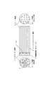
図1は、本発明によるバイオセンサ形イメージングファイバ装置のバイオセンサおよび光ファイバ部分の詳細を説明するための図である。
バンドルファイバ2は多数の光ファイバ素線3を束ねて形成したものであり、その先端部2aにはバイオセンサ(細胞)1が取り付けられている。取り付け方法は光ファイバの先端にバイオセンサ1を培養するものである。バイオセンサ1の前面側にはセルロースなどの繊維構造よりなる物質選択膜4を張り付けてある。物質選択膜4は多数の小さい孔が形成されており、孔より小さい特別な物質などを通過させるような構造である。
Hereinafter, embodiments of the present invention will be described in detail with reference to the drawings.
FIG. 1 is a view for explaining details of a biosensor and an optical fiber portion of a biosensor type imaging fiber device according to the present invention.
The
端面を正面から観察すると、多数のバイオセンサが配置され、その背後に多数のファイバ素線3が配置され、バイオセンサの変化する光学信号がファイバ素線3の検出側端面2aに入射するようになっている。
これら光学信号はファイバ素線3を介して光センサ側の端面2bに導かれる。多数のファイバ素線3から光信号をCCDなどの撮像素子で受光することによりバイオセンサの2次元のイメージ情報を得ることができる。
バンドルファイバの径は例えば1〜10mmであり、その先端部は比較的柔軟な構造であり、ファイバの先端付近を少し曲げることが可能である。
When the end face is observed from the front, a large number of biosensors are arranged, a large number of fiber strands 3 are arranged behind the end faces, and an optical signal changed by the biosensor is incident on the detection-
These optical signals are guided to the
The diameter of the bundle fiber is, for example, 1 to 10 mm, and the tip portion has a relatively flexible structure, and the vicinity of the fiber tip can be bent slightly.
図2は、バイオセンサの例を説明するための図である。
(a)の蛍光標識化細胞(非特異的)は、多種類の受容体を発現するもので、多くのホルモンを感知することができる。○,△,Yで示される部分がそれぞれの受容体11a,11b,11cで、各種の受容体が発現しているものである。このバイオセンサでは多種類の生体内微量物質を感知することが可能である。
また、(b)は人工で作った細胞膜で、ある特定の物質のみを感知するような受容体12aだけを発現させたり、イオン感受性蛍光指示薬で染めてあったり、蛍光タンパク質を発現させてあるものである。
例えば、(b)のバイオセンサでは目的の微量物質と反応するとCa応答を示し、Ca依存的に蛍光強度の変化(またはスペクトル変化)が起こる。
FIG. 2 is a diagram for explaining an example of a biosensor.
The fluorescently labeled cells (non-specific) of (a) express many kinds of receptors and can detect many hormones. The portions indicated by ◯, Δ, and Y are the
(B) is an artificially produced cell membrane that expresses only the
For example, when the biosensor (b) reacts with a target trace substance, it shows a Ca response, and a fluorescence intensity change (or spectrum change) occurs depending on Ca.
図3は、単一受容体再構成人工膜によるバイオセンサについて、リガンドとなる生体内微量物質の存否による変化を説明するための図である。
測定したい物質、例えばホルモンが存在しない場合には受容体12aは反応することはなく、バイオセンサ12は照射される光に対し、発する蛍光は弱いものである。または、色のスペクトルは青色である。
観測すべき生体内にホルモン13が存在すると、ホルモン13は受容体12aと反応を起こし、バイオセンサ12は蛍光の強度が増加する。または青色であったものが赤い色に変化する。
FIG. 3 is a diagram for explaining a change due to the presence / absence of a trace substance in a living body as a ligand in a biosensor using a single receptor reconstituted artificial membrane.
In the absence of a substance to be measured, such as a hormone, the
If the hormone 13 is present in the living body to be observed, the hormone 13 reacts with the
図4は、バイオセンサから出力される蛍光強度−波長特性の光出力特性の変化例を示す波形図である。
(a)はある特定領域波長の蛍光強度のみを変化させる生体内微量物質が存在する場合である。縦軸は蛍光強度、横軸は波長で、生体内微量物質の物質が増加するにしたがって反応する受容体が増加し、特性15aに示すように当初波形の中央部のレベルが低かったものが、生体内微量物質との反応量にしたがって、特性15b,15c,15dとなって波形の中央部の蛍光強度が大きくなる。
FIG. 4 is a waveform diagram showing a change example of the light output characteristic of the fluorescence intensity-wavelength characteristic output from the biosensor.
(A) is a case where there is a trace substance in the living body that changes only the fluorescence intensity of a specific region wavelength. The vertical axis is the fluorescence intensity, the horizontal axis is the wavelength, the number of receptors that react as the amount of trace substances in the body increases, and the level of the central part of the initial waveform is low as shown in the characteristic 15a. According to the amount of reaction with the trace substance in the living body, the
つぎに(b)は蛍光強度および色の両方が変化する生体内微量物質が存在する場合である。1種類の生体内微量物質の受容体または複数の生体内微量物質の存在でこのような特性となる。
生体内微量物質が存在しない場合、または存在が少ない場合には特性16aとなる。生体内微量物質の存在が多くなると、波長のピークが長い波長にずれるとともに蛍光強度のピークも小さくなり、特性16b,16c,16dに示すようになる。
(c)は色変化のみ生ずる生体内微量物質が存在する場合である。当初特性17aであったものが、生体内微量物質の増加に伴い、同一の波形形状の特性の中心位置が長波長側にずれ、特性17b,17c,17dに示すようになる。
Next, (b) shows a case where there is a trace substance in the living body in which both the fluorescence intensity and the color change. Such a characteristic is caused by the presence of a receptor for one kind of in vivo trace substance or a plurality of in vivo trace substances.
When the in-vivo trace substance does not exist or when the presence is small, the characteristic 16a is obtained. When the presence of a trace substance in the living body increases, the peak of the wavelength shifts to a longer wavelength and the peak of the fluorescence intensity also decreases, as shown in the
(C) is a case where there is a trace substance in the living body that causes only a color change. The initial characteristic 17a is shifted to the longer wavelength side with the increase of trace substances in the living body, and the
図5は、本発明によるバイオセンサ形イメージングファイバ装置に蛍光顕微鏡の光学系を適用したシステムの実施の形態を示す図である。
バイオセンサ1,バンドルファイバ2および物質選択膜4の構成は、図1の構成と同じであり、バイオセンサ1を取り付けたバンドルファイバ2の先端は生体の挿入孔を通して測定すべき生体内の目的位置に挿入される。
図示しない光制御部の制御の下に半導体レーザやキセノンランプ等の光源20を起動させると、光源20の励起光は集光レンズ21,励起フィルタ22,レンズ23を通過し、ダイクロイックミラー24で反射され、集光レンズ25によりバンドルファイバ2の光センサ側端面2bに導かれる。
FIG. 5 is a diagram showing an embodiment of a system in which an optical system of a fluorescence microscope is applied to a biosensor type imaging fiber device according to the present invention.
The configuration of the biosensor 1, the
When the light source 20 such as a semiconductor laser or a xenon lamp is activated under the control of a light control unit (not shown), the excitation light of the light source 20 passes through the
バンドルファイバ2の光センサ側端面2bに入射した光は、バンドルファイバ2の先端部に伝達され、細胞内に照射される。もし細胞の近傍に生体内微量物質が存在する場合には、バイオセンサ1は蛍光信号の輝度変化を起こし、蛍光強度が増加するか、またはバイオセンサの色が変化する。この光信号はバンドルファイバ2の光センサ側端面2bから出力され、集光レンズ25,ダイクロイックミラー24を通過し、さらにダイクロイックミラー24の背後にある蛍光を通過させる蛍光フィルタ(バンドパスフィルタ)26,集光レンズ27を介してCCD28に入射する。CCD28は映像制御回路29により制御され、光信号のイメージは電気信号に変換され、所定処理がなされて画像表示部30に送られる。画像表示部30では、バイオセンサの2次元像を観測することができ、ホルモンの分布や密度を検出することができる。
The light that has entered the optical sensor
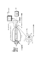
図6は、多分岐形のバンドルファイバを用い、バイオセンサ形イメージングファイバの他にイメージも検出できるシステムの実施の形態を示す図である。
この例は、バイオセンサにより生体内微量物質の存在を捉えながら、観察対象も同時に光学的に検出できるようにしたものである。
マルチイメージングファイバ装置38は制御回路37,バンドルファイバの分岐部40,光スキャナ39を備えている。制御回路37はレーザ光源36からの光導入や、バンドルファイバの分岐部40へのファイバへの光入力およびバンドルファイバの分岐部40から光出力を行うための光スキャナ39を制御する機能を有している。さらにバンドルファイバの分岐部40から出力した光データをカメラ・モニタ35に送出する制御も行う。
FIG. 6 is a diagram showing an embodiment of a system that uses a multi-branch bundle fiber and can detect an image in addition to a biosensor-type imaging fiber.
In this example, an observation target can be optically detected at the same time while the presence of a trace substance in a living body is detected by a biosensor.
The multi-imaging fiber device 38 includes a control circuit 37, a bundle fiber branching unit 40, and an optical scanner 39. The control circuit 37 has a function of controlling the optical scanner 39 for introducing light from the
バンドルファイバ分岐部40ではバイオセンサ付イメージファイバ31およびイメージ専用ファイバ32に対し、レーザ光源36から送られてくる光が分岐される。
バンドルファイバ分岐部40のバイオセンサ付イメージファイバ31およびイメージ専用ファイバ32の端面に対し、それぞれの端面を照射するようにレーザ光36aが当てられ、図示しない端面照射切替機構により順次照射端面が切り替えられていく。
バイオセンサ付イメージファイバ31は生体内微量物質34により蛍光変化を検出し、イメージ専用ファイバ32は臓器または疾病領域中における観察対象のイメージを撮像する。これら変化した蛍光および撮像光はそれぞれ、バンドルファイバ分岐部40に戻り、カメラ・モニタ35に出力される。バイオ付バンドルファイバの先端部はフレキシブル構造であるため、複数のバイオ付バンドルファイバそれぞれを、その先端部を曲げて異なる角度から観察対象に近づけることができる。また、複数のバイオ付バンドルファイバの一部を観察対象の周囲に向けて周辺の状態を同時に観察することも可能である。
この例はレーザ光源36からの光を切り替えることにより多数のバンドルファイバ(バイオ付イメージファイバ2個,イメージ専用ファイバ2個)に分岐する構成を採用するものであるが、レーザ光源36からの光を分割して多数のバンドルファイバに同時に光を供給することも可能である。かかる場合には4個のファイバ端面を同時に照射するように光学系が構成される。これらの端面切替機構および分割照射機構は、本件出願人がすでに提案している切替形イメージングファイバ装置(特願2005−331860)および分割形イメージングファイバ装置(特願2005−331533)の構成を利用することができる。
バイオ付イメージファイバ31およびイメージ専用ファイバ32の数はこの例に限らず、さらに多数のバンドルファイバを設置することが可能である。
In the bundle fiber branching unit 40, the light transmitted from the
Laser light 36a is applied to the end faces of the
The
This example employs a configuration in which the light from the
The number of the
具体例として従来の装置は生体内の対象部分を観察するか、または、その部分の物質の測定のいずれしかできないものであった。
しかしながら、本発明によれば、鉗子を入れる部分,内視鏡挿入部分,バイオセンサ付きバンドルファイバを挿入部分を備えたカテーテルで用いることにより、モニタをしながら微量物質の測定を行い、かつ治療を行うことが可能となる。また、複数種類のバイオセンサ付きバンドルファイバ(マルチイメージングファイバ)を同時に使うことができるようにもなる。また、本発明によるバイオセンサ付きバンドルファイバは測定機能付きの蛍光顕微鏡として応用することができる。
As a specific example, a conventional apparatus can only observe a target portion in a living body or measure a substance in that portion.
However, according to the present invention, a part for inserting a forceps, an endoscope insertion part, and a bundle fiber with a biosensor are used in a catheter provided with the insertion part, so that a trace substance can be measured while monitoring and treatment can be performed. Can be done. In addition, bundle fibers (multi-imaging fibers) with a plurality of types of biosensors can be used simultaneously. The bundle fiber with a biosensor according to the present invention can be applied as a fluorescence microscope with a measurement function.
蛍光顕微鏡の光学系を接続することにより、生体や臓器におけるホルモンや神経伝達物質などの微量物質の濃度や2次元分布を観察しながら治療ができるバイオセンサ付きイメージファイバ装置である。 This is an image fiber device with a biosensor that can be treated while observing the concentration and two-dimensional distribution of trace substances such as hormones and neurotransmitters in living bodies and organs by connecting an optical system of a fluorescence microscope.
1 バイオセンサ(細胞)
2 バンドルファイバ(IF)
2a バンドルファイバ検出側端面
2b バンドルファイバ光センサ側端面
3 光ファイバ素線
4 物質選択膜(セルロース)
11 蛍光標識化細胞
12 単一受容体再構成人工膜
20 光源
21,23,25,27 レンズ
22 励起フィルタ
24 ダイクロイックミラー
26 蛍光フィルタ
28 CCD
29 映像制御回路
30 画像表示部
31 バイオセンサ付イメージファイバ
32 イメージ専用ファイバ
33 臓器または疾病領域中における観察対象
34 生体内微量物質
35 カメラ・モニタ
36 レーザ光源
37 制御回路
38 マルチイメージングファイバ装置
1 Biosensor (cell)
2 Bundled fiber (IF)
2a Bundle fiber detection
11 Fluorescently labeled cells
12 Single Receptor Reconstruction Artificial Membrane 20
DESCRIPTION OF
Claims (5)
単数または複数の波長の光を発生しうる光源と、
多数のファイバ素線を束ね、前記バイオセンサを前記ファイバ束の先端部に配置したバンドルファイバと、
前記バンドルファイバ先端に配置したバイオセンサを覆い、前記特定の物質のみを通過させる透過孔を有する物質選択膜と、
前記バンドルファイバの出力端に設けられた光源からの励起光とバイオセンサからの信号光を分離する光学的手段と、
前記バンドルファイバの出力端に設けられ、前記バイオセンサの映像変化を取得する測定手段と、
を備え、
前記バンドルファイバは、複数有し、その一部にイメージ検出形バンドルファイバを含むとともにバイオ付バンドルファイバはフレイキシブル構造であり、
バイオ付バンドルファイバはそれぞれ異なる角度から近づけて観察対象を捉えるとともに前記イメージ検出形バンドルファイバでイメージも検出することを特徴とするバイオセンサ形イメージングファイバ装置。 A biosensor that changes its light output characteristics by expressing a large number of receptors or a single receptor present in cells in response to a specific biological trace substance,
A light source capable of generating light of one or more wavelengths;
A bundle fiber in which a large number of fiber strands are bundled, and the biosensor is arranged at the tip of the fiber bundle,
A material selection membrane that covers a biosensor disposed at the tip of the bundle fiber and has a permeation hole that allows only the specific material to pass through;
Optical means for separating excitation light from a light source and signal light from a biosensor provided at an output end of the bundle fiber;
Measuring means provided at the output end of the bundle fiber to acquire the image change of the biosensor;
Equipped with a,
The bundle fiber has a plurality, and includes an image detection type bundle fiber in a part thereof, and the bundle fiber with bio has a flexible structure,
A biosensor-type imaging fiber device characterized in that the bundle fiber with bio is brought close to each other from different angles to catch an observation object and an image is also detected by the image-detection-type bundle fiber .
前記バイオセンサは該ホルモンに反応して蛍光強度が増加、または反応前の出力波長に対し長いまたは短い波長の光を出力することを特徴とする請求項1,2または3記載のバイオセンサ形イメージングファイバ装置。 The specific substance is a trace substance in a living body such as a hormone or a neurotransmitter,
4. The biosensor-type imaging according to claim 1, wherein the biosensor increases fluorescence intensity in response to the hormone, or outputs light having a longer or shorter wavelength than an output wavelength before the reaction. Fiber device.
前記撮像素子出力端から2次元画像を得ることを特徴とする請求項1,2,3または4記載のバイオセンサ形イメージングファイバ装置。 The measurement means is a video camera that obtains an image by arranging an image sensor at an output end of the bundle fiber,
5. The biosensor type imaging fiber device according to claim 1, wherein a two-dimensional image is obtained from the output end of the imaging device.
Priority Applications (1)
| Application Number | Priority Date | Filing Date | Title |
|---|---|---|---|
| JP2007031783A JP4912908B2 (en) | 2007-02-13 | 2007-02-13 | Biosensor type imaging fiber device |
Applications Claiming Priority (1)
| Application Number | Priority Date | Filing Date | Title |
|---|---|---|---|
| JP2007031783A JP4912908B2 (en) | 2007-02-13 | 2007-02-13 | Biosensor type imaging fiber device |
Publications (2)
| Publication Number | Publication Date |
|---|---|
| JP2008196940A JP2008196940A (en) | 2008-08-28 |
| JP4912908B2 true JP4912908B2 (en) | 2012-04-11 |
Family
ID=39756032
Family Applications (1)
| Application Number | Title | Priority Date | Filing Date |
|---|---|---|---|
| JP2007031783A Expired - Fee Related JP4912908B2 (en) | 2007-02-13 | 2007-02-13 | Biosensor type imaging fiber device |
Country Status (1)
| Country | Link |
|---|---|
| JP (1) | JP4912908B2 (en) |
Cited By (1)
| Publication number | Priority date | Publication date | Assignee | Title |
|---|---|---|---|---|
| CN103149190A (en) * | 2013-03-18 | 2013-06-12 | 厦门大学 | Toilet intelligent health care detection system |
Families Citing this family (1)
| Publication number | Priority date | Publication date | Assignee | Title |
|---|---|---|---|---|
| JP7613709B2 (en) * | 2020-05-26 | 2025-01-15 | 国立大学法人 東京大学 | Fiber optic sensors and detectors |
Family Cites Families (6)
| Publication number | Priority date | Publication date | Assignee | Title |
|---|---|---|---|---|
| JPH0713597B2 (en) * | 1989-01-19 | 1995-02-15 | テルモ株式会社 | Oxygen concentration measuring tool |
| JP3305398B2 (en) * | 1993-03-31 | 2002-07-22 | 三菱レイヨン株式会社 | Optical fiber sensor |
| US5837196A (en) * | 1996-01-26 | 1998-11-17 | The Regents Of The University Of California | High density array fabrication and readout method for a fiber optic biosensor |
| US6210910B1 (en) * | 1998-03-02 | 2001-04-03 | Trustees Of Tufts College | Optical fiber biosensor array comprising cell populations confined to microcavities |
| JP2002340900A (en) * | 2001-05-18 | 2002-11-27 | Mitsubishi Rayon Co Ltd | Biosensor, biosensor array and detection method |
| US7787923B2 (en) * | 2003-11-26 | 2010-08-31 | Becton, Dickinson And Company | Fiber optic device for sensing analytes and method of making same |
-
2007
- 2007-02-13 JP JP2007031783A patent/JP4912908B2/en not_active Expired - Fee Related
Cited By (2)
| Publication number | Priority date | Publication date | Assignee | Title |
|---|---|---|---|---|
| CN103149190A (en) * | 2013-03-18 | 2013-06-12 | 厦门大学 | Toilet intelligent health care detection system |
| CN103149190B (en) * | 2013-03-18 | 2015-05-13 | 厦门大学 | Toilet intelligent health care detection system |
Also Published As
| Publication number | Publication date |
|---|---|
| JP2008196940A (en) | 2008-08-28 |
Similar Documents
| Publication | Publication Date | Title |
|---|---|---|
| KR100893519B1 (en) | System and method for detecting body cavity state in vivo | |
| US10314490B2 (en) | Method and device for multi-spectral photonic imaging | |
| US8188446B2 (en) | Fluorescence imaging apparatus | |
| US9795338B2 (en) | Apparatus and method for detecting NIR fluorescence at sentinel lymph node | |
| JP5275217B2 (en) | Systems for in vivo analysis | |
| Guo et al. | Miniature multiplexed label-free pH probe in vivo | |
| CN103105353B (en) | Single cell detector based on nano optical fiber probe and probe manufacturing method thereof | |
| JPH08224209A (en) | Fluorescence observing device | |
| US20110012025A1 (en) | Fluorescence observation apparatus | |
| JP2009065848A (en) | Method for analyzing expression of gene and system for analyzing expression of gene | |
| JPH08224210A (en) | Fluorescence observing device | |
| JP4912908B2 (en) | Biosensor type imaging fiber device | |
| JP2005287964A (en) | Observation apparatus for observing living body, organ and tissue | |
| EP3460585B1 (en) | An imaging device for in-line holographic imaging of an object | |
| JP5800462B2 (en) | Optical signal analysis method | |
| JP5784857B1 (en) | Endoscope main body apparatus and endoscope system | |
| JPH06281822A (en) | Measuring instrument in living body | |
| WO2016096908A1 (en) | Biosensor based on single-molecule fluorescence detection | |
| US20220000386A1 (en) | Catheter, guide wire, opening position identification device, opening position identification method, internal object presence determination assistance device, diagnostic assistance device, and treatment assistance device | |
| JP5060931B2 (en) | Calcium measurement method | |
| JP2021188942A (en) | Fiber sensor and detector | |
| Jo et al. | Miniaturized fiber-coupled microscope with cell-embedded hydrogel for odorant sensing | |
| KR20200070912A (en) | Image picup module for endoscope and medical endoscope synchronized multiplex medical image based on separate imaging | |
| US20090008559A1 (en) | Apparatus for Analyzing Cells in Real-time | |
| KR20190014026A (en) | Probe unit and optical imaging apparatus therewith and controlling method thereof |
Legal Events
| Date | Code | Title | Description |
|---|---|---|---|
| A521 | Request for written amendment filed |
Free format text: JAPANESE INTERMEDIATE CODE: A523 Effective date: 20070302 |
|
| A621 | Written request for application examination |
Free format text: JAPANESE INTERMEDIATE CODE: A621 Effective date: 20091225 |
|
| A977 | Report on retrieval |
Free format text: JAPANESE INTERMEDIATE CODE: A971007 Effective date: 20111110 |
|
| A131 | Notification of reasons for refusal |
Free format text: JAPANESE INTERMEDIATE CODE: A131 Effective date: 20111115 |
|
| A521 | Request for written amendment filed |
Free format text: JAPANESE INTERMEDIATE CODE: A523 Effective date: 20111212 |
|
| TRDD | Decision of grant or rejection written | ||
| A01 | Written decision to grant a patent or to grant a registration (utility model) |
Free format text: JAPANESE INTERMEDIATE CODE: A01 Effective date: 20120110 |
|
| A01 | Written decision to grant a patent or to grant a registration (utility model) |
Free format text: JAPANESE INTERMEDIATE CODE: A01 |
|
| A61 | First payment of annual fees (during grant procedure) |
Free format text: JAPANESE INTERMEDIATE CODE: A61 Effective date: 20120118 |
|
| R150 | Certificate of patent or registration of utility model |
Ref document number: 4912908 Country of ref document: JP Free format text: JAPANESE INTERMEDIATE CODE: R150 Free format text: JAPANESE INTERMEDIATE CODE: R150 |
|
| FPAY | Renewal fee payment (event date is renewal date of database) |
Free format text: PAYMENT UNTIL: 20150127 Year of fee payment: 3 |
|
| R250 | Receipt of annual fees |
Free format text: JAPANESE INTERMEDIATE CODE: R250 |
|
| R250 | Receipt of annual fees |
Free format text: JAPANESE INTERMEDIATE CODE: R250 |
|
| R250 | Receipt of annual fees |
Free format text: JAPANESE INTERMEDIATE CODE: R250 |
|
| R250 | Receipt of annual fees |
Free format text: JAPANESE INTERMEDIATE CODE: R250 |
|
| R250 | Receipt of annual fees |
Free format text: JAPANESE INTERMEDIATE CODE: R250 |
|
| R250 | Receipt of annual fees |
Free format text: JAPANESE INTERMEDIATE CODE: R250 |
|
| R250 | Receipt of annual fees |
Free format text: JAPANESE INTERMEDIATE CODE: R250 |
|
| R250 | Receipt of annual fees |
Free format text: JAPANESE INTERMEDIATE CODE: R250 |
|
| R250 | Receipt of annual fees |
Free format text: JAPANESE INTERMEDIATE CODE: R250 |
|
| R250 | Receipt of annual fees |
Free format text: JAPANESE INTERMEDIATE CODE: R250 |
|
| LAPS | Cancellation because of no payment of annual fees |