JP4910345B2 - Fuel cell system - Google Patents
Fuel cell system Download PDFInfo
- Publication number
- JP4910345B2 JP4910345B2 JP2005276084A JP2005276084A JP4910345B2 JP 4910345 B2 JP4910345 B2 JP 4910345B2 JP 2005276084 A JP2005276084 A JP 2005276084A JP 2005276084 A JP2005276084 A JP 2005276084A JP 4910345 B2 JP4910345 B2 JP 4910345B2
- Authority
- JP
- Japan
- Prior art keywords
- torque
- value
- limit
- fuel cell
- target
- Prior art date
- Legal status (The legal status is an assumption and is not a legal conclusion. Google has not performed a legal analysis and makes no representation as to the accuracy of the status listed.)
- Expired - Fee Related
Links
Images


Classifications
-
- Y—GENERAL TAGGING OF NEW TECHNOLOGICAL DEVELOPMENTS; GENERAL TAGGING OF CROSS-SECTIONAL TECHNOLOGIES SPANNING OVER SEVERAL SECTIONS OF THE IPC; TECHNICAL SUBJECTS COVERED BY FORMER USPC CROSS-REFERENCE ART COLLECTIONS [XRACs] AND DIGESTS
- Y02—TECHNOLOGIES OR APPLICATIONS FOR MITIGATION OR ADAPTATION AGAINST CLIMATE CHANGE
- Y02E—REDUCTION OF GREENHOUSE GAS [GHG] EMISSIONS, RELATED TO ENERGY GENERATION, TRANSMISSION OR DISTRIBUTION
- Y02E60/00—Enabling technologies; Technologies with a potential or indirect contribution to GHG emissions mitigation
- Y02E60/30—Hydrogen technology
- Y02E60/50—Fuel cells
Description
本発明は、水素及び空気の供給により発電する燃料電池を備えた燃料電池システムに関する。 The present invention relates to a fuel cell system including a fuel cell that generates electricity by supplying hydrogen and air.
燃料電池システムは、燃料電池のアノードに燃料となる水素、カソードに酸化剤となる空気を供給し、これらアノードとカソード間に挟持された電解質膜で電極反応を生じさせることによって発電電力を得る発電システムである。このような燃料電池システムは、クリーンな排気や高エネルギ効率を実現できることから、例えば車両用駆動源などの用途に大きな期待が寄せられている。 The fuel cell system supplies hydrogen as fuel to the anode of the fuel cell and air as oxidant to the cathode, and generates electric power by generating an electrode reaction with an electrolyte membrane sandwiched between the anode and cathode. System. Since such a fuel cell system can realize clean exhaust and high energy efficiency, there is a great expectation for applications such as a vehicle drive source.
ところで、例えば車両などに搭載される燃料電池システムでは、通常、コンプレッサ等で大気を吸入、加圧して燃料電池のカソードに供給するようにしているが、例えば高地のような大気圧が低い場所を車両が走行する場合にはコンプレッサで吸入する空気密度が低下しているため、コンプレッサモータのトルクや回転数を通常時よりも増大させる必要が生じる。このとき、コンプレッサモータの能力を超えるような回転数やトルクを当該コンプレッサモータに要求して、燃料電池から大電流を取り出そうとすると、コンプレッサモータの故障や燃料電池の耐久性低下などを招いてしまうことになる。そこで、大気圧を検出して、検出した大気圧に応じて燃料電池からの取出電流を制限することで、コンプレッサや燃料電池を保護するといった技術も提案されている(例えば、特許文献1参照。)。
しかしながら、燃料電池システムにおいて空気供給装置として使用されるコンプレッサは、必ずしもその性能が一定となっているわけではなく、性能に多少のばらつきが見られるのが現状である。そのため、コンプレッサの性能のばらつきを考慮して、コンプレッサモータの能力を超えるような回転数やトルクが要求されることを確実に回避するためには、燃料電池からの取出電流の制限をきつめにかける設定としておく必要があり、過剰な制限となって動力性能低下の要因となっている場合が多かった。 However, the performance of a compressor used as an air supply device in a fuel cell system is not always constant, and there are some variations in performance. For this reason, in consideration of variations in compressor performance, it is strictly necessary to limit the extraction current from the fuel cell in order to reliably avoid demands for rotational speed and torque that exceed the capacity of the compressor motor. It was necessary to set it to be applied, and there were many cases where it became an excessive restriction and a factor of a decrease in power performance.
本発明は、以上のような従来の実情に鑑みて創案されたものであって、空気供給装置の性能に応じて最適なモータのトルク制御を行い、過剰な出力制限をかけることなく、空気供給装置や燃料電池の保護を確実に図ることができる燃料電池システムを提供することを目的としている。 The present invention was devised in view of the conventional situation as described above, and optimally controls the torque of the motor according to the performance of the air supply device, and supplies air without excessive output limitation. It aims at providing the fuel cell system which can aim at protection of an apparatus and a fuel cell reliably.
本発明に係る燃料電池システムは、モータの回転数などに応じて設定される目標制限トルクだけでなく、現在のモータトルク値もパラメータとして用いて、燃料電池からの取出電力または取出電流を制限することで、前記課題を解決する。すなわち、本発明の燃料電池システムは、目標制限トルク設定手段と、モータトルク検出手段と、出力制限手段とを備え、出力制限手段が、目標制限トルク設定手段で設定された目標トルクと、モータトルク検出手段で検出あるいは推定された現在のモータトルク値とに応じて、燃料電池からの取出電力または取出電流に制限をかけるようにしている。 The fuel cell system according to the present invention limits not only the target limit torque set according to the number of revolutions of the motor but also the current motor torque value as a parameter, thereby limiting the extraction power or extraction current from the fuel cell. This solves the problem. That is, the fuel cell system of the present invention includes target limit torque setting means, motor torque detection means, and output limit means, and the output limit means sets the target torque set by the target limit torque setting means and the motor torque. Depending on the current motor torque value detected or estimated by the detection means, the extraction power or extraction current from the fuel cell is limited.
また、本発明に係る他の燃料電池システムは、モータの回転数などに応じて設定される目標制限トルクだけでなく、現在のモータトルク値もパラメータとして用いて、燃料電池のカソードに供給する空気の圧力を制限することで、前記課題を解決する。すなわち、本発明の燃料電池システムは、目標制限トルク設定手段と、モータトルク検出手段と、空気圧力制限手段とを備え、空気圧力制限手段が、目標制限トルク設定手段で設定された目標トルクと、モータトルク検出手段で検出あるいは推定された現在のモータトルク値とに応じて、燃料電池のカソードに供給する空気の圧力に制限をかけるようにしている。 Further, another fuel cell system according to the present invention uses not only the target limit torque set according to the number of revolutions of the motor but also the current motor torque value as a parameter, and supplies the air supplied to the cathode of the fuel cell. The above-mentioned problem is solved by limiting the pressure. That is, the fuel cell system of the present invention includes target limit torque setting means, motor torque detection means, and air pressure limit means, wherein the air pressure limit means is set to the target torque set by the target limit torque setting means, The pressure of the air supplied to the cathode of the fuel cell is limited in accordance with the current motor torque value detected or estimated by the motor torque detecting means.
本発明の燃料電池システムによれば、空気供給装置の性能に応じて最適なモータのトルク制御が行われるので、過剰な出力制限をかけることによる動力性能低下などの問題を有効に回避しながら、空気供給装置や燃料電池の保護を確実に図ることができる。 According to the fuel cell system of the present invention, since optimal motor torque control is performed according to the performance of the air supply device, while effectively avoiding problems such as power performance degradation due to excessive output limitation, The air supply device and the fuel cell can be reliably protected.
以下、本発明を適用した燃料電池システムの具体的な実施形態について、図面を参照しながら詳細に説明する。 Hereinafter, specific embodiments of a fuel cell system to which the present invention is applied will be described in detail with reference to the drawings.
(第1の実施形態)
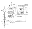
第1の実施形態の燃料電池システムの要部構成を図1に示す。本実施形態の燃料電池システムは、例えば車両に搭載されて車両の動力源として用いられるものであり、発電を行う燃料電池1を備える。
(First embodiment)
FIG. 1 shows the main configuration of the fuel cell system according to the first embodiment. The fuel cell system of the present embodiment is mounted on a vehicle and used as a power source of the vehicle, for example, and includes a
燃料電池1は、水素が供給されるアノード(燃料極)と空気が供給されるカソード(酸化剤極)とが電解質を挟んで重ね合わされて発電セルが構成されるとともに、複数の発電セルが多段積層されたスタック構造を有し、電解質での電極反応により化学エネルギを電気エネルギに変換するものである。この燃料電池1の各発電セルでは、アノードに供給された水素が水素イオンと電子とに分離される反応が起き、水素イオンは電解質を通り、電子は外部回路を通って電力を発生させ、カソード側にそれぞれ移動する。カソードでは、供給された空気中の酸素と電解質を通って移動した水素イオン及び電子が反応して水が生成され、外部に排出される。すなわち、燃料電池1では、以下に示す電極反応が進行し、電力が発電される。
The
アノード(燃料極): H2→2H++2e− (1)
カソード(酸化剤極): 2H++2e−+(1/2)O2→H2O (2)
燃料電池1の電解質としては、高エネルギ密度化、低コスト化、軽量化等を考慮して、例えば固体高分子電解質膜が用いられる。固体高分子電解質膜は、例えばフッ素樹脂系イオン交換膜等、イオン(プロトン)伝導性の高分子膜からなるものであり、飽和含水することによりイオン伝導性電解質として機能する。
Anode (fuel electrode): H 2 → 2H + + 2e − (1)
Cathode (oxidant electrode): 2H + + 2e − + (1/2) O 2 → H 2 O (2)
As the electrolyte of the
以上のように、燃料電池1で発電を行うには、この燃料電池1のカソードに酸化剤ガスである空気、アノードに燃料ガスである水素をそれぞれ供給する必要があり、そのための機構が空気供給系及び水素供給系である。
As described above, in order to generate power in the
ここで、空気供給系は、外気を吸入し燃料電池1のカソードに空気を圧送するためのコンプレッサ(空気供給装置)2、空気供給管3、カソード排ガスを排出するための空気排気管4、及び空気調圧弁5を備えた構成とされている。空気は、前記コンプレッサ2により加圧して空気供給管3に送り込まれ、燃料電池1のカソードに供給される。燃料電池1で消費されなかった酸素及び空気中の他の成分は、空気排気管4から大気中に排出される。また、カソードの空気圧は、圧力センサ6によって検出され、空気調圧弁5を駆動することにより制御される。
Here, the air supply system includes a compressor (air supply device) 2 for sucking outside air and pumping air to the cathode of the
水素供給系は、例えば、水素供給源である水素タンクから取り出した高圧水素を減圧弁、水素調圧弁を介して圧力調整し、水素供給管から燃料電池1のアノードに供給する構成とされている。なお、水素供給系は、本発明に直接かかわる部分ではないので、図示及び詳細な説明を省略する。
The hydrogen supply system is configured, for example, to adjust the pressure of high-pressure hydrogen taken out from a hydrogen tank that is a hydrogen supply source via a pressure reducing valve and a hydrogen pressure regulating valve, and supply the high pressure hydrogen to the anode of the
本実施形態の燃料電池システムにおいて、燃料電池1で発生した電力(電流)は、パワーマネージャ7により取り出され、例えば車両の駆動モータなどに供給される。そして、本実施形態の燃料電池システムは、このパワーマネージャ7による燃料電池1からの電力(電流)の取り出しを制御するための制御系として、モータトルク検出手段8、コンプレッサ回転数検出手段9、目標制限トルク設定手段10、大気圧センサ11、出力制限手段12を備える。
In the fuel cell system of the present embodiment, power (current) generated in the
モータトルク検出手段8は、コンプレッサ2の駆動源であるコンプレッサモータの現在のトルク値を検出あるいは推定するものである。具体的には、このモータトルク検出手段8は、例えば、モータ駆動電流などからコンプレッサモータの現在のトルク値を推定し、あるいは、トルクセンサなどを用いて、コンプレッサモータの現在のトルク値を検出する。
The motor torque detection means 8 detects or estimates the current torque value of the compressor motor that is the drive source of the
コンプレッサ回転数検出手段9は、コンプレッサモータの回転数(すなわち、コンプレッサ2の回転数)を検出するものである。具体的には、このコンプレッサ回転数検出手段9は、例えば、レゾルバやエンコーダなどのセンサを用いて、コンプレッサモータの回転数を検出する。 The compressor rotation speed detection means 9 detects the rotation speed of the compressor motor (that is, the rotation speed of the compressor 2). Specifically, the compressor rotation speed detection means 9 detects the rotation speed of the compressor motor using a sensor such as a resolver or an encoder.
目標制限トルク設定手段10は、コンプレッサモータのトルクが当該コンプレッサモータの能力を超えないように制限するための目標制限トルクを設定するものである。具体的には、この目標制限トルク設定手段10は、例えば、図2のようなコンプレッサモータの回転数と上限トルクとの関係を表すマップを用い、コンプレッサ回転数検出手段9によって検出されたコンプレッサモータの回転数に応じて、当該回転数のときにコンプレッサモータで出力可能な上限トルクを目標制限トルクとして設定する。 The target limit torque setting means 10 sets a target limit torque for limiting the torque of the compressor motor so as not to exceed the capacity of the compressor motor. Specifically, the target limit torque setting means 10 uses, for example, a map representing the relationship between the rotation speed of the compressor motor and the upper limit torque as shown in FIG. 2, and the compressor motor detected by the compressor rotation speed detection means 9. The upper limit torque that can be output by the compressor motor at the rotation speed is set as the target limit torque.
なお、このとき、目標制限トルク設定手段10は、コンプレッサ回転数検出手段9によって検出されたコンプレッサモータの回転数をそのままマップの入力値として用いるのではなく、図2に示すように、一次遅れフィルタを用いてコンプレッサ回転数検出手段9によって検出されたコンプレッサモータの回転数に補正をかけた出力をマップの入力値として目標制限トルクを設定することが望ましい。 At this time, the target limit torque setting means 10 does not use the rotation speed of the compressor motor detected by the compressor rotation speed detection means 9 as it is as an input value of the map, but as shown in FIG. It is desirable to set the target limit torque using the output obtained by correcting the rotational speed of the compressor motor detected by the compressor rotational speed detection means 9 as the input value of the map.
すなわち、本実施形態の燃料電池システムでは、後述するように、この目標制限トルク設定手段10で設定された目標制限トルクと、モータトルク検出手段8で検出あるいは推定されたコンプレッサモータの現在のトルク値とに応じて、出力制限手段12によって燃料電池1からの取出電流が制限されるが、燃料電池1からの取出電流が制限されると、空気流量が減少するのでコンプレッサモータの回転数が下がり、それに応じて目標制限トルクが上がるので、燃料電池1からの取出電流の制限が緩和されることになる。そして、燃料電池1からの取出電流の制限が緩和されると、コンプレッサモータの回転数が上がって、それに応じて目標制限トルクが下がり、燃料電池1からの取出電流の制限がきつくかかるようになるといった現象が繰り返されることになる。このため、目標制限トルクの演算と燃料電池1からの取出電流制限の演算とが干渉して、取出電流制限にハンチングを生じさせてしまう要因となることが懸念されるが、上述したように、コンプレッサ回転数検出手段9によって検出されたコンプレッサモータの回転数に一次遅れフィルタを用いて補正をかけた出力に応じて目標制限トルクを設定するようにすれば、コンプレッサモータの回転数の変動をなまして、目標制限トルクの演算と燃料電池1からの取出電流制限値の演算との干渉を回避することができ、取出電流制限にハンチングを生じさせるといった問題を有効に抑制することが可能となる。
That is, in the fuel cell system of the present embodiment, as will be described later, the target torque limit set by the target torque limit setting means 10 and the current torque value of the compressor motor detected or estimated by the motor torque detection means 8. Accordingly, the output current from the
大気圧センサ11は、大気圧を検出する圧力センサである。この大気圧センサ11は出力制限手段12に接続されており、当該大気圧センサ11によって検出された大気圧の情報は、出力制限手段12に入力される。
The
出力制限手段12は、目標制限トルク設定手段10で設定された目標制限トルクと、モータトルク検出手段8で検出あるいは推定されたコンプレッサモータの現在のトルク値とに応じて、燃料電池1からの取出電流に制限をかけるものであり、入力制限トルク補正部12a、出力制限値演算部12b、制限部12cを有する。なお、ここでは、出力制限手段12が、燃料電池1からの取出電流に制限をかけるものとして説明するが、電流と電圧の双方、すなわち燃料電池1からの取出電力に制限をかけるようにしてもよい。燃料電池1からの取出電力に制限をかける場合も、制御の内容は、燃料電池1からの取出電流に制限をかける場合と同様である。
The
入力制限トルク補正部12aは、目標制限トルク設定手段10によって設定された目標制限トルクと、モータトルク検出手段8によって検出あるいは推定された現在のモータトルク値との偏差に応じて、出力制限値演算部12bでの演算に用いる目標制限トルクを補正して、第2の目標制限トルクとして算出するものである。
The input limit
出力制限値演算部12bは、入力制限トルク補正部12aによって算出された第2の目標制限トルクと、大気圧センサ11によって検出された大気圧に応じて、燃料電池1からの取出電流を制限するための電流制限値を算出するものである。
The output limit
制限部12cは、燃料電池1からの目標取出電流を、出力制限値演算部12bで算出された電流制限値に制限するものである。すなわち、制限部12cは、例えば駆動モータの動作状況などに応じて燃料電池1に要求される目標取出電流が、出力制限値演算部12bで算出された電流制限値よりも小さければ、当該目標取出電流を取出電流指令値としてパワーマネージャ7に出力し、目標取出電流が電流制限値よりも大きければ、電流制限値を取出電流指令値としてパワーマネージャ7に出力する。これにより、燃料電池1からの取出電流が、電流制限値に制限されることになる。
The
出力制限手段12における制御の具体例を図3に示す。この図3に示す例において、入力制限トルク補正部12aは、目標制限トルク設定手段10で設定された目標制限トルクとモータトルク検出手段8で検出あるいは推定された現在のモータトルク値との偏差に応じた入力トルク補正値を求め、この入力トルク補正値を用いて目標制限トルク設定手段10で設定された目標制限トルクを補正することで、第2の目標制限トルクを算出する。そして、この第2の目標制限トルクを出力制限値演算部12bに入力する。
A specific example of control in the
出力制限値演算部12bは、例えば、燃料電池1からの取出電流値とその電流値を燃料電池1から取り出せるようにするためにコンプレッサモータに要求される必要トルクとの関係を大気圧毎に表したマップを用い、入力制限トルク補正部12aから入力された第2の目標制限トルクと、大気圧センサ11によって検出された大気圧とに基づいて、現在の大気圧でコンプレッサモータのモータトルクを第2の目標制限トルクに制限したときに燃料電池1から取り出すことが可能な電流値を、電流制限値として算出する。
The output limit
制限部12cは、燃料電池1の目標取出電流と、出力制限値演算部12bで算出された電流制限値をセレクトローして、取出電流指令値としてパワーマネージャ7に出力することによって、燃料電池1からの取出電流を制限する。
The limiting
ここで、出力制限値演算部12bでの演算に用いられるマップは、例えば図4に示すような手法で作成される。すなわち、燃料電池1からの取出電流に応じて燃料電池1のカソードに供給する空気流量と圧力(カソード運転圧力)を定める。コンプレッサ2から燃料電池1までの空気系圧損は供給空気流量によって決まるので、空気系圧損とカソード運転圧力から、コンプレッサ2における吐出空気圧力が決まる。そして、大気圧とコンプレッサ2の吐出空気圧力からコンプレッサ入出の圧力比が決まり、コンプレッサモータの必要トルクが求まる。この必要トルクをグラフ横軸(マップ入力値)とし、燃料電池1からの取出電流をグラフ縦軸(マップ出力値)とし、これを大気圧毎に作成すれば、出力制限のマップが完成する。
Here, the map used for the calculation in the output limit
このように、出力制限値演算部12bで演算に用いられるマップは、燃料電池1からの取出電流とコンプレッサモータの必要トルクに基づいて設計されており、モータトルク検出手段8で検出あるいは推定されたコンプレッサモータの現在のモータトルク値が、目標制限トルク設定手段10で設定された目標制限トルクからずれた場合には、ずれたトルク偏差をマップの入力に戻して補正することによって、コンプレッサモータのモータトルク値を目標制限トルクに近づかせることができる。
As described above, the map used for the calculation by the output limit
燃料電池1からの取出電流の制限と、その制限によるコンプレッサモータのモータトルクの応答との関係を図5に示す。なお、図5(a)は、目標制限トルク設定手段10で設定された目標制限トルクを補正することなくマップ入力値として電流制限値を求める場合の例であり、図5(b)は、目標制限トルク設定手段10で設定された目標制限トルクをコンプレッサモータの現在のモータトルク値との偏差に応じて補正した上でマップ入力値として電流制限値を求める場合の例である。
FIG. 5 shows the relationship between the limitation on the extraction current from the
図5(a)に示す例では、コンプレッサ2やコンプレッサモータの性能ばらつき、さらには経時劣化などに応じて、コンプレッサモータのモータトルク値が目標制限トルクを超えることがある。したがって、この図5(a)に示す例では、コンプレッサモータのモータトルク値が目標制限トルクを超えないようにするためには、目標制限トルクに応じて電流制限がきつめに掛かるように出力制限のマップを設定しなくてはならない。
In the example shown in FIG. 5A, the motor torque value of the compressor motor may exceed the target limit torque depending on the performance variation of the
これに対して、図5(b)に示す例では、設定されている目標制限トルクとコンプレッサモータの現在のモータトルク値との偏差を、出力制限値演算部12bでの演算に用いるマップの入力トルクに上のせすることによって、燃料電池1からの取出電流がさらに制限されて、モータトルク値のオーバーシュートを軽減できる。したがって、この図5(b)に示す例では、コンプレッサやコンプレッサモータの性能ばらつきなどを考慮して、あらかじめ電流制限がきつめに掛かるように設定しなくてもよい。
On the other hand, in the example shown in FIG. 5 (b), the map input used for calculating the deviation between the set target limit torque and the current motor torque value of the compressor motor in the output limit
以上、具体的な例を挙げて詳細に説明したように、本実施形態の燃料電池システムでは、モータトルク検出手段8でコンプレッサモータの現在のモータトルク値を検出あるいは推定し、目標制限トルクだけでなく現在のモータトルク値も用いて、燃料電池1からの取出電流を制限するようにしているので、コンプレッサモータのモータトルク値を許容トルク以下に精度良く抑制することができる。したがって、この燃料電池システムにおいては、コンプレッサ2やコンプレッサモータの性能ばらつきなどを考慮して燃料電池1からの取出電流を過剰に制限する必要がなく、コンプレッサモータの上限出力を使いきり、燃料電池1のカソードに供給する空気流量を増やして動力性能を向上させることができるとともに、コンプレッサ2やコンプレッサモータ、燃料電池1などの保護を確実に図ることができる。
As described above in detail with specific examples, in the fuel cell system of the present embodiment, the motor torque detection means 8 detects or estimates the current motor torque value of the compressor motor, and only the target limit torque is used. Since the current motor torque value is also used to limit the extraction current from the
なお、燃料電池1からの取出電流を過剰に制限しないようにするためには、コンプレッサモータとして高出力のモータを用いることも考えられるが、高出力のモータを採用するとコンプレッサの大型化、ひいてはシステム全体の大型化を招くことになり、また、コストアップの要因となる。これに対して、本実施形態の燃料電池システムでは、高出力のモータを採用するといった部品の過剰設計をする必要もなく、安価でコンパクトなシステムを実現できる。
In order not to excessively limit the extraction current from the
また、本実施形態の燃料電池システムにおいては、目標制限トルク設定手段9で設定された目標制限トルクと、モータトルク検出手段8で検出あるいは推定されたコンプレッサモータの現在のモータトルク値との偏差に応じて、出力制限手段12での電流制限値の演算に用いる目標制限トルクを補正する、すなわち、目標制限トルクと現在のモータトルク値との偏差をフィードバックしながら電流制限値を算出するようにしているので、コンプレッサモータのモータトルク値を許容トルク以下に抑制する制御を、極めて高精度に行うことができる。 In the fuel cell system of the present embodiment, the deviation between the target limit torque set by the target limit torque setting means 9 and the current motor torque value of the compressor motor detected or estimated by the motor torque detection means 8 is calculated. Accordingly, the target limit torque used for the calculation of the current limit value in the output limit means 12 is corrected, that is, the current limit value is calculated while feeding back the deviation between the target limit torque and the current motor torque value. Therefore, the control for suppressing the motor torque value of the compressor motor below the allowable torque can be performed with extremely high accuracy.
また、本実施形態の燃料電池システムにおいては、出力制限手段12での電流制限値の演算の際に大気圧も考慮して、高地などの大気圧が低いところでは電流制限がきつくかかるように電流制限値を算出するようにしているので、使用環境の変化にも対応しながら、コンプレッサモータのモータトルク値を許容トルク以下に抑制する制御を、極めて高精度に行うことができる。
In the fuel cell system of the present embodiment, the current limit value is calculated by the
また、本実施形態の燃料電池システムにおいては、目標制限トルク設定手段10が、コンプレッサ回転数検出手段9によって検出されたコンプレッサモータの回転数に応じて、コンプレッサモータのトルクがその能力を超えないように制限するための目標制限トルクを設定するようにしているので、モータ回転数に応じて上限トルク値が定まるような一般的なコンプレッサモータのトルク制御を極めて高精度に行うことができる。また、コンプレッサモータの回転数が高い領域で上限トルク値を低く設定することで、回転数が高い領域ではコンプレッサモータのトルクが大きく制限されることになるので、コンプレッサモータの回転数が過剰な回転数とならないように制限することも可能となる。 Further, in the fuel cell system of the present embodiment, the target limit torque setting means 10 causes the compressor motor torque not to exceed its capacity according to the compressor motor speed detected by the compressor speed detection means 9. Since the target limit torque is set to limit the torque to the normal value, the general compressor motor torque control in which the upper limit torque value is determined according to the motor rotation speed can be performed with extremely high accuracy. In addition, by setting the upper limit torque value low in the region where the compressor motor speed is high, the compressor motor torque is greatly restricted in the region where the compressor speed is high. It is also possible to limit the number so that it does not become a number.
(第2の実施形態)
次に、本発明を適用した第2の実施形態の燃料電池システムについて説明する。
(Second Embodiment)
Next, a fuel cell system according to a second embodiment to which the present invention is applied will be described.
第2の実施形態の燃料電池システムの要部構成を図6に示す。本実施形態の燃料電池システムは、図6に示すように、上述した第1の実施形態における出力制限手段12とパワーマネージャ7の代わりに、空気圧力制限手段21と空気圧力制御手段22とを備えたものである。すなわち、上述した第1の実施形態の燃料電池システムでは、目標制限トルク設定手段10で設定された目標制限トルクと、モータトルク検出手段8で検出あるいは推定されたコンプレッサモータの現在のトルク値とに応じて、燃料電池1からの取出電流に制限をかけるようにしているが、本実施形態の燃料電池システムにおいては、目標制限トルク設定手段10で設定された目標制限トルクと、モータトルク検出手段8で検出あるいは推定されたコンプレッサモータの現在のトルク値とに応じて、燃料電池1のカソードに供給する空気の圧力(燃料電池1のカソード運転圧力)に制限をかけるようにしている。つまり、本実施形態の燃料電池システムでは、燃料電池1のカソードに供給する空気の圧力(カソード運転圧力)に制限をかけることで、コンプレッサ2の吸入側と吐出側の空気圧縮比を下げ、コンプレッサモータのモータトルク値を許容トルク以下に抑制できるようにしている。
The principal part structure of the fuel cell system of 2nd Embodiment is shown in FIG. As shown in FIG. 6, the fuel cell system of this embodiment includes an air
なお、本実施形態の燃料電池システムにおけるその他の構成や制御の基本部分は、上述した第1の実施形態と共通であるので、以下、第1の実施形態との共通部分については図中同一の符号を付して重複した説明を省略し、本実施形態に特徴的な空気圧力制限手段21および空気圧力制御手段22とその制御内容を中心に説明する。
In addition, since the other configuration and the basic part of the control in the fuel cell system of this embodiment are the same as those in the first embodiment described above, the common parts with the first embodiment are the same in the drawings. The description will be omitted with overlapping reference numerals, and the air
空気圧力制限手段21は、目標制限トルク設定手段10で設定された目標制限トルクと、モータトルク検出手段8で検出あるいは推定されたコンプレッサモータの現在のトルク値とに応じて、燃料電池1のカソードに供給する空気の圧力に制限をかけるものであり、入力制限トルク補正部21a、空気圧力制限値演算部21b、制限部21cを有する。
The air
入力制限トルク補正部21aは、目標制限トルク設定手段10によって設定された目標制限トルクと、モータトルク検出手段8によって検出あるいは推定された現在のモータトルク値との偏差に応じて、空気圧力制限値演算部21bでの演算に用いる目標制限トルクを補正して、第2の目標制限トルクとして算出するものである。
The input limit
空気圧力制限値演算部21bは、入力制限トルク補正部21aによって算出された第2の目標制限トルクと、大気圧センサ11によって検出された大気圧に応じて、燃料電池1のカソードに供給する空気の圧力を制限するための空気圧力制限値を算出するものである。
The air pressure limit
制限部21cは、燃料電池1のカソードに供給する空気の圧力を、空気圧力制限値演算部21bで算出された空気圧力制限値に制限するものである。すなわち、制限部21cは、燃料電池1に要求される発電量に対応した目標空気圧力が、空気圧力制限値演算部21bで算出された空気圧力制限値よりも小さければ、当該目標空気圧力を空気圧力制御指令値として空気圧力制御手段22に出力し、目標空気圧力が空気圧力制限値よりも大きければ、空気圧力制限値を空気圧力制御指令値として空気圧力制御手段22に出力する。
The limiting
空気圧力制御手段22は、空気圧力制限手段21の制限部21cから出力される空気圧力制御指令値と、圧力センサ6によって検出される現在の空気圧力とに応じて、調圧弁5の開度を調整することで、燃料電池1のカソードに供給される空気の圧力を制御する。これにより、本実施形態の燃料電池システムにおいては、燃料電池1のカソードに供給される空気の圧力が、空気圧力制限手段21の空気圧力制限値演算部21bで算出された空気圧力制限値に制限されることになる。
The air pressure control means 22 adjusts the opening of the pressure regulating valve 5 according to the air pressure control command value output from the
空気圧力制限手段21における制御の具体例を図7に示す。この図7に示す例において、入力制限トルク補正部21aは、目標制限トルク設定手段10で設定された目標制限トルクとモータトルク検出手段8で検出あるいは推定された現在のモータトルク値との偏差に応じた入力トルク補正値を求め、この入力トルク補正値を用いて目標制限トルク設定手段10で設定された目標制限トルクを補正することで、第2の目標制限トルクを算出する。そして、この第2の目標制限トルクを空気圧力制限値演算部21bに入力する。
A specific example of control in the air
空気圧力制限値演算部21bは、例えば、燃料電池1のカソードに供給する空気の圧力(燃料電池1のカソード運転圧力)とその空気圧力を実現するためにコンプレッサモータに要求される必要トルクとの関係を大気圧毎に表したマップを用い、入力制限トルク補正部21aから入力された第2の目標制限トルクと、大気圧センサ11によって検出された大気圧とに基づいて、現在の大気圧でコンプレッサモータのモータトルクを第2の目標制限トルクに制限したときに実現可能な上限圧力を、空気圧力制限値として算出する。
For example, the air pressure limit
制限部21cは、燃料電池1に要求される発電量に対応した目標空気圧力と、空気圧力制限値演算部21bで算出された空気圧力制限値をセレクトローして、空気圧力制御指令値として空気圧力制御手段22に出力することによって、燃料電池1のカソードに供給する空気の圧力(カソード運転圧力)を制限する。
The limiting
ここで、空気圧力制限値演算部21bでの演算に用いられるマップは、燃料電池1のカソード運転圧力とコンプレッサモータの必要トルクに基づいて設計されており、モータトルク検出手段8で検出あるいは推定されたコンプレッサモータの現在のモータトルク値が、目標制限トルク設定手段10で設定された目標制限トルクからずれた場合には、ずれたトルク偏差をマップの入力に戻して補正することによって、コンプレッサモータのモータトルク値を目標制限トルクに近づかせることができる。
Here, the map used for the calculation in the air pressure limit
以上、具体的な例を挙げて詳細に説明したように、本実施形態の燃料電池システムでは、モータトルク検出手段8でコンプレッサモータの現在のモータトルク値を検出あるいは推定し、目標制限トルクだけでなく現在のモータトルク値も用いて、燃料電池1のカソードに供給する空気の圧力を制限するようにしているので、コンプレッサモータのモータトルク値を許容トルク以下に精度良く抑制することができる。したがって、この燃料電池システムにおいては、上述した第1の実施形態の燃料電池システムと同様に、コンプレッサ2やコンプレッサモータの性能ばらつきなどを考慮して燃料電池1からの取出電流を過剰に制限する必要がなく、コンプレッサモータの上限出力を使いきり、燃料電池1のカソードに供給する空気流量を増やして動力性能を向上させることができるとともに、コンプレッサ2やコンプレッサモータ、燃料電池1などの保護を確実に図ることができる。
As described above in detail with specific examples, in the fuel cell system of the present embodiment, the motor torque detection means 8 detects or estimates the current motor torque value of the compressor motor, and only the target limit torque is used. Since the current motor torque value is also used and the pressure of the air supplied to the cathode of the
また、本実施形態の燃料電池システムでは、上述した第1の実施形態の燃料電池システムと同様に、高出力のモータを採用するといった部品の過剰設計をする必要もなく、安価でコンパクトなシステムを実現できる。 Further, in the fuel cell system of the present embodiment, as with the fuel cell system of the first embodiment described above, there is no need to overdesign parts such as employing a high output motor, and an inexpensive and compact system can be achieved. realizable.
また、本実施形態の燃料電池システムでは、燃料電池1からの取出電流(電力)を制限する代わりに、燃料電池1のカソードに供給する空気圧力を制限するようにして、コンプレッサ2の吸入側と吐出側の空気圧縮比を下げ、コンプレッサモータのモータトルク値を許容トルク以下に抑制できるようにしているので、燃料電池1からの取出電流(電力)を制限することに起因する動力性能低下をさらに効果的に回避しながら、コンプレッサ2やコンプレッサモータ、燃料電池1などの保護を確実に図ることができる。
Further, in the fuel cell system of this embodiment, instead of limiting the extraction current (electric power) from the
また、本実施形態の燃料電池システムにおいては、目標制限トルク設定手段9で設定された目標制限トルクと、モータトルク検出手段8で検出あるいは推定されたコンプレッサモータの現在のモータトルク値との偏差に応じて、空気圧力制限手段21での空気圧力制限値の演算に用いる目標制限トルクを補正する、すなわち、目標制限トルクと現在のモータトルク値との偏差をフィードバックしながら空気圧力制限値を算出するようにしているので、コンプレッサモータのモータトルク値を許容トルク以下に抑制する制御を、極めて高精度に行うことができる。 In the fuel cell system of the present embodiment, the deviation between the target limit torque set by the target limit torque setting means 9 and the current motor torque value of the compressor motor detected or estimated by the motor torque detection means 8 is calculated. Accordingly, the target limit torque used for the calculation of the air pressure limit value in the air pressure limit means 21 is corrected, that is, the air pressure limit value is calculated while feeding back the deviation between the target limit torque and the current motor torque value. As a result, the control for suppressing the motor torque value of the compressor motor below the allowable torque can be performed with extremely high accuracy.
(第3の実施形態)
次に、本発明を適用した第3の実施形態の燃料電池システムについて説明する。
(Third embodiment)
Next, a fuel cell system according to a third embodiment to which the present invention is applied will be described.
第3の実施形態の燃料電池システムの要部構成を図8に示す。本実施形態の燃料電池システムは、図8に示すように、上述した第1の実施形態における出力制限手段12の代わりに、出力制限手段31を備えたものである。すなわち、上述した第1の実施形態の燃料電池システムでは、目標制限トルク設定手段9で設定された目標制限トルクと、モータトルク検出手段8で検出あるいは推定されたコンプレッサモータの現在のモータトルク値との偏差に応じて、出力制限手段12での電流制限値の演算に用いる目標制限トルクを補正するようにしているが、本実施形態の燃料電池システムにおいては、目標制限トルク設定手段9で設定された目標制限トルクと、モータトルク検出手段8で検出あるいは推定されたコンプレッサモータの現在のモータトルク値との偏差に応じて、出力制限手段31で目標制限トルクに基づいて算出された電流制限値を補正するようにしている。
The principal part structure of the fuel cell system of 3rd Embodiment is shown in FIG. As shown in FIG. 8, the fuel cell system of this embodiment includes an
なお、本実施形態の燃料電池システムにおけるその他の構成や制御の基本部分は、上述した第1の実施形態と共通であるので、以下、第1の実施形態との共通部分については図中同一の符号を付して重複した説明を省略し、本実施形態に特徴的な出力制限手段31の構成およびその制御内容を中心に説明する。
In addition, since the other configuration and the basic part of the control in the fuel cell system of this embodiment are the same as those in the first embodiment described above, the common parts with the first embodiment are the same in the drawings. The description will be omitted with the reference numerals added, and the description will focus on the configuration of the
出力制限手段31は、目標制限トルク設定手段10で設定された目標制限トルクと、モータトルク検出手段8で検出あるいは推定されたコンプレッサモータの現在のトルク値とに応じて、燃料電池1からの取出電流に制限をかけるものであり、出力制限値演算部31a、出力制限値補正部31b、制限部31cを有する。なお、ここでは、出力制限手段31が、燃料電池1からの取出電流に制限をかけるものとして説明するが、電流と電圧の双方、すなわち燃料電池1からの取出電力に制限をかけるようにしてもよい。燃料電池1からの取出電力に制限をかける場合も、制御の内容は、燃料電池1からの取出電流に制限をかける場合と同様である。
The
出力制限値演算部31aは、目標制限トルク設定手段10によって設定された目標制限トルクと、大気圧センサ11によって検出された大気圧に応じて、燃料電池1からの取出電流を制限するための電流制限値を算出するものである。
The output limit
出力制限値補正部31bは、目標制限トルク設定手段10によって設定された目標制限トルクと、モータトルク検出手段8によって検出あるいは推定された現在のモータトルク値との偏差、および当該偏差の積分値に応じて、出力制限値演算部31aで算出された電流制限値を補正するものである。
The output limit
制限部31cは、燃料電池1からの目標取出電流を、出力制限値演算部31aで算出されて出力制限値補正部31bで補正された電流制限値に制限するものである。すなわち、制限部31cは、例えば駆動モータの動作状況などに応じて燃料電池1に要求される目標取出電流が、出力制限値演算部31aで算出されて出力制限値補正部31bで補正された電流制限値よりも小さければ、当該目標取出電流を取出電流指令値としてパワーマネージャ7に出力し、目標取出電流が電流制限値よりも大きければ、電流制限値を取出電流指令値としてパワーマネージャ7に出力する。これにより、燃料電池1からの取出電流が、電流制限値に制限されることになる。
The limiting
出力制限手段31における制御の具体例を図9に示す。この図9に示す例において、出力制限値演算部31aは、例えば、燃料電池1からの取出電流値とその電流値を燃料電池1から取り出せるようにするためにコンプレッサモータに要求される必要トルクとの関係を大気圧毎に表したマップを用い、目標制限トルク設定手段10で設定された目標制限トルクと、大気圧センサ11によって検出された大気圧とに基づいて、現在の大気圧でコンプレッサモータのモータトルクを目標制限トルクに制限したときに燃料電池1から取り出すことが可能な電流値を、電流制限値として算出する。
A specific example of control in the
出力制限値補正部31bは、目標制限トルク設定手段10で設定された目標制限トルクとモータトルク検出手段8で検出あるいは推定された現在のモータトルク値との偏差、および当該偏差の積分値に応じた電流制限補正値を求め、この電流制限補正値を用いて、出力制限値演算部31aで算出された電流制限値を補正する。
The output limit
制限部31cは、燃料電池1の目標取出電流と、出力制限値演算部31aで算出されて出力制限値補正部31bで補正された電流制限値をセレクトローして、取出電流指令値としてパワーマネージャ7に出力することによって、燃料電池1からの取出電流を制限する。
The limiting
以上のように、本実施形態の燃料電池システムにおける出力制限手段31では、モータトルク検出手段8で検出あるいは推定されたコンプレッサモータの現在のモータトルク値が、目標制限トルク設定手段10で設定された目標制限トルクからずれた場合に、ずれたトルク偏差がフィードバックされて電流制限値が調整されるので、コンプレッサモータのモータトルク値を許容トルク以下に精度良く抑制することができる。
As described above, in the
本実施形態の燃料電池システムでの燃料電池1からの取出電流の制限と、その制限によるコンプレッサモータのモータトルクの応答との関係を図10に示す。この図10に示すように、本実施形態の燃料電池システムでは、目標制限トルクとコンプレッサモータの現在のモータトルク値との偏差をフィードバックして電流制限値を調整することで、コンプレッサモータのモータトルク値を目標制限トルクに近づけることができ、さらに、目標制限トルクとコンプレッサモータの現在のモータトルク値との偏差を積分してフィードバックしているので、定常的には偏差をゼロに近づけることができる。
FIG. 10 shows the relationship between the limitation of the extraction current from the
以上、具体的な例を挙げて詳細に説明したように、本実施形態の燃料電池システムでは、モータトルク検出手段8でコンプレッサモータの現在のモータトルク値を検出あるいは推定し、目標制限トルクだけでなく現在のモータトルク値も用いて、燃料電池1からの取出電流を制限するようにしているので、コンプレッサモータのモータトルク値を許容トルク以下に精度良く抑制することができる。したがって、この燃料電池システムにおいては、上述した第1の実施形態の燃料電池システムと同様に、コンプレッサ2やコンプレッサモータの性能ばらつきなどを考慮して燃料電池1からの取出電流を過剰に制限する必要がなく、コンプレッサモータの上限出力を使いきり、燃料電池1のカソードに供給する空気流量を増やして動力性能を向上させることができるとともに、コンプレッサ2やコンプレッサモータ、燃料電池1などの保護を確実に図ることができる。
As described above in detail with specific examples, in the fuel cell system of the present embodiment, the motor torque detection means 8 detects or estimates the current motor torque value of the compressor motor, and only the target limit torque is used. Since the current motor torque value is also used to limit the extraction current from the
また、本実施形態の燃料電池システムでは、上述した第1の実施形態の燃料電池システムと同様に、高出力のモータを採用するといった部品の過剰設計をする必要もなく、安価でコンパクトなシステムを実現できる。 Further, in the fuel cell system of the present embodiment, as with the fuel cell system of the first embodiment described above, there is no need to overdesign parts such as employing a high output motor, and an inexpensive and compact system can be achieved. realizable.
また、本実施形態の燃料電池システムにおいては、目標制限トルク設定手段9で設定された目標制限トルクと、モータトルク検出手段8で検出あるいは推定されたコンプレッサモータの現在のモータトルク値との偏差に応じて、出力制限手段31で目標制限トルクに基づいて算出された電流制限値を補正する、すなわち、目標制限トルクと現在のモータトルク値との偏差をフィードバックしながら電流制限値を算出するようにしているので、コンプレッサモータのモータトルク値を許容トルク以下に抑制する制御を、極めて高精度に行うことができる。
In the fuel cell system of the present embodiment, the deviation between the target limit torque set by the target limit torque setting means 9 and the current motor torque value of the compressor motor detected or estimated by the motor torque detection means 8 is calculated. Accordingly, the current limiting value calculated based on the target limiting torque is corrected by the
(第4の実施形態)
次に、本発明を適用した第4の実施形態の燃料電池システムについて説明する。
(Fourth embodiment)
Next, a fuel cell system according to a fourth embodiment to which the present invention is applied will be described.
第4の実施形態の燃料電池システムの要部構成を図11に示す。本実施形態の燃料電池システムは、図11に示すように、上述した第2の実施形態における空気圧力制限手段21の代わりに、空気圧力制限手段41を備えたものである。すなわち、上述した第2の実施形態の燃料電池システムでは、目標制限トルク設定手段9で設定された目標制限トルクと、モータトルク検出手段8で検出あるいは推定されたコンプレッサモータの現在のモータトルク値との偏差に応じて、空気圧力制限手段21での空気圧力制限値の演算に用いる目標制限トルクを補正するようにしているが、本実施形態の燃料電池システムにおいては、目標制限トルク設定手段9で設定された目標制限トルクと、モータトルク検出手段8で検出あるいは推定されたコンプレッサモータの現在のモータトルク値との偏差に応じて、空気圧力制限手段41で目標制限トルクに基づいて算出された空気圧力制限値を補正するようにしている。
FIG. 11 shows the main configuration of the fuel cell system according to the fourth embodiment. As shown in FIG. 11, the fuel cell system of this embodiment includes an air
なお、本実施形態の燃料電池システムにおけるその他の構成や制御の基本部分は、上述した第2の実施形態と共通であるので、以下、第2の実施形態との共通部分については図中同一の符号を付して重複した説明を省略し、本実施形態に特徴的な空気圧力制限手段41の構成およびその制御内容を中心に説明する。 In addition, since the other structure and the basic part of control in the fuel cell system of this embodiment are the same as those in the second embodiment described above, the common parts with the second embodiment are the same in the drawings. The description will be omitted with overlapping reference numerals, and the configuration and control contents of the air pressure limiting means 41 characteristic of this embodiment will be mainly described.
空気圧力制限手段41は、目標制限トルク設定手段10で設定された目標制限トルクと、モータトルク検出手段8で検出あるいは推定されたコンプレッサモータの現在のトルク値とに応じて、燃料電池1のカソードに供給する空気の圧力(燃料電池1のカソード運転圧力)に制限をかけるものであり、空気圧力制限値演算部41a、空気圧力制限値補正部41b、制限部41cを有する。
The air
空気圧力制限値演算部41aは、目標制限トルク設定手段10によって設定された目標制限トルクと、大気圧センサ11によって検出された大気圧に応じて、燃料電池1のカソードに供給する空気の圧力を制限するための空気圧力制限値を算出するものである。
The air pressure limit
空気圧力制限値補正部41bは、目標制限トルク設定手段10によって設定された目標制限トルクと、モータトルク検出手段8によって検出あるいは推定された現在のモータトルク値との偏差、および当該偏差の積分値に応じて、空気圧力制限値演算部41aで算出された空気圧力制限値を補正するものである。
The air pressure limit
制限部41cは、燃料電池1のカソードに供給する空気の圧力を、空気圧力制限値演算部41aで算出されて空気圧力制限値補正部41bで補正された空気圧力制限値に制限するものである。すなわち、制限部41cは、燃料電池1に要求される発電量に対応した目標空気圧力が、空気圧力制限値演算部41aで算出されて空気圧力制限値補正部41bで補正された空気圧力制限値よりも小さければ、当該目標空気圧力を空気圧力制御指令値として空気圧力制御手段22に出力し、目標空気圧力が空気圧力制限値よりも大きければ、空気圧力制限値を空気圧力制御指令値として空気圧力制御手段22に出力する。
The
空気圧力制御手段22は、空気圧力制限手段41の制限部41cから出力される空気圧力制御指令値と、圧力センサ6によって検出される現在の空気圧力とに応じて、調圧弁5の開度を調整することで、燃料電池1のカソードに供給される空気の圧力を制御する。これにより、本実施形態の燃料電池システムにおいては、燃料電池1のカソードに供給される空気の圧力が、空気圧力制限手段41の空気圧力制限値演算部41aで算出されて空気圧力制限値補正部41bで補正された空気圧力制限値に制限されることになる。
The air pressure control means 22 adjusts the opening of the pressure regulating valve 5 according to the air pressure control command value output from the
空気圧力制限手段41における制御の具体例を図12に示す。この図12に示す例において、空気圧力制限値演算部41aは、例えば、燃料電池1のカソードに供給する空気の圧力(燃料電池1のカソード運転圧力)とその空気圧力を実現するためにコンプレッサモータに要求される必要トルクとの関係を大気圧毎に表したマップを用い、目標制限トルク設定手段10で設定された目標制限トルクと、大気圧センサ11によって検出された大気圧とに基づいて、現在の大気圧でコンプレッサモータのモータトルクを目標制限トルクに制限したときに実現可能な上限圧力を、空気圧力制限値として算出する。
A specific example of control in the air
空気圧力制限値補正部41bは、目標制限トルク設定手段10で設定された目標制限トルクとモータトルク検出手段8で検出あるいは推定された現在のモータトルク値との偏差、および当該偏差の積分値に応じた空気圧力制限補正値を求め、この空気圧力制限補正値を用いて、空気圧力制限値演算部41aで算出された空気圧力制限値を補正する。
The air pressure limit
制限部41cは、燃料電池1に要求される発電量に対応した目標空気圧力と、空気圧力制限値演算部41aで算出されて空気圧力制限値補正部41bで補正された空気圧力制限値をセレクトローして、空気圧力制御指令値として空気圧力制御手段22に出力することによって、燃料電池1のカソードに供給する空気の圧力(カソード運転圧力)を制限する。
The
以上のように、本実施形態の燃料電池システムにおける空気圧力制限手段41では、モータトルク検出手段8で検出あるいは推定されたコンプレッサモータの現在のモータトルク値が、目標制限トルク設定手段10で設定された目標制限トルクからずれた場合に、ずれたトルク偏差がフィードバックされて空気圧力制限値が調整されるので、コンプレッサモータのモータトルク値を許容トルク以下に精度良く抑制することができる。
As described above, in the air pressure limiting means 41 in the fuel cell system of the present embodiment, the current motor torque value of the compressor motor detected or estimated by the motor
以上、具体的な例を挙げて詳細に説明したように、本実施形態の燃料電池システムでは、モータトルク検出手段8でコンプレッサモータの現在のモータトルク値を検出あるいは推定し、目標制限トルクだけでなく現在のモータトルク値も用いて、燃料電池1のカソードに供給する空気の圧力を制限するようにしているので、コンプレッサモータのモータトルク値を許容トルク以下に精度良く抑制することができる。したがって、この燃料電池システムにおいては、上述した第2の実施形態の燃料電池システムと同様に、コンプレッサ2やコンプレッサモータの性能ばらつきなどを考慮して燃料電池1からの取出電流を過剰に制限する必要がなく、コンプレッサモータの上限出力を使いきり、燃料電池1のカソードに供給する空気流量を増やして動力性能を向上させることができるとともに、コンプレッサ2やコンプレッサモータ、燃料電池1などの保護を確実に図ることができる。
As described above in detail with specific examples, in the fuel cell system of the present embodiment, the motor torque detection means 8 detects or estimates the current motor torque value of the compressor motor, and only the target limit torque is used. Since the current motor torque value is also used and the pressure of the air supplied to the cathode of the
また、本実施形態の燃料電池システムでは、上述した第2の実施形態の燃料電池システムと同様に、高出力のモータを採用するといった部品の過剰設計をする必要もなく、安価でコンパクトなシステムを実現できる。 Further, in the fuel cell system of the present embodiment, similarly to the fuel cell system of the second embodiment described above, there is no need to overdesign parts such as adopting a high output motor, and an inexpensive and compact system can be achieved. realizable.
また、本実施形態の燃料電池システムでは、燃料電池1からの取出電流(電力)を制限する代わりに、燃料電池1のカソードに供給する空気圧力を制限するようにして、コンプレッサ2の吸入側と吐出側の空気圧縮比を下げ、コンプレッサモータのモータトルク値を許容トルク以下に抑制できるようにしているので、燃料電池1からの取出電流(電力)を制限することに起因する動力性能低下をさらに効果的に回避しながら、コンプレッサ2やコンプレッサモータ、燃料電池1などの保護を確実に図ることができる。
Further, in the fuel cell system of this embodiment, instead of limiting the extraction current (electric power) from the
また、本実施形態の燃料電池システムにおいては、目標制限トルク設定手段9で設定された目標制限トルクと、モータトルク検出手段8で検出あるいは推定されたコンプレッサモータの現在のモータトルク値との偏差に応じて、空気圧力制限手段41で目標制限トルクに基づいて算出された空気圧力制限値を補正する、すなわち、目標制限トルクと現在のモータトルク値との偏差をフィードバックしながら空気圧力制限値を算出するようにしているので、コンプレッサモータのモータトルク値を許容トルク以下に抑制する制御を、極めて高精度に行うことができる。
In the fuel cell system of the present embodiment, the deviation between the target limit torque set by the target limit torque setting means 9 and the current motor torque value of the compressor motor detected or estimated by the motor torque detection means 8 is calculated. Accordingly, the
(第5の実施形態)
次に、本発明を適用した第5の実施形態の燃料電池システムについて説明する。
(Fifth embodiment)
Next, a fuel cell system according to a fifth embodiment to which the present invention is applied will be described.
第5の実施形態の燃料電池システムは、上述した第3の実施形態の燃料電池システムの構成(図8参照)を前提とし、出力制限手段31の出力制限値補正部31bが電流制限値を補正する際の演算方法に特徴を有するものである。すなわち、本実施形態の燃料電池システムでは、出力制限手段31の出力制限値補正部31bが電流制限値を補正する際に、目標制限トルク設定手段10で設定された目標制限トルクとモータトルク検出手段8で検出あるいは推定された現在のモータトルク値との偏差と、当該偏差の積分値であって下限値のリミッタが設定された積分値とに応じて電流制限補正値を求め、この電流制限補正値を用いて、出力制限値演算部31aで算出された電流制限値を補正するようにしている。
The fuel cell system of the fifth embodiment is based on the configuration of the fuel cell system of the third embodiment described above (see FIG. 8), and the output limit
また、本実施形態の燃料電池システムでは、モータトルク検出手段8で検出あるいは推定された現在のモータトルク値が、目標制限トルク設定手段10で設定された目標制限トルクよりも所定値αだけ低い値に設定された第1の閾値以上となったときに、出力制限手段31の出力制限値補正部31bによる補正演算を実施し、この補正演算を実施した後、目標制限トルク設定手段10で設定された目標制限トルクよりも所定値β(β>α)だけ低い値に設定された第2の閾値(第2の閾値<第1の閾値)未満となったときに、補正演算を終了するようにしている。さらにまた、本実施形態の燃料電池システムでは、出力制限手段31の出力制限値補正部31bによる補正演算を終了した後、次の補正演算を開始するまでの間は、前回の補正演算のときの積分値(目標制限トルクとモータトルク値との偏差の積分値)を保持するようにしている。
In the fuel cell system of the present embodiment, the current motor torque value detected or estimated by the motor
本実施形態の燃料電池システムにおける出力制限手段31での制御の具体例を図13に示す。この図13に示す例において、出力制限値演算部31aおよび制限部31cでの処理内容は、上述した第3の実施形態の燃料電池システム(図9参照)と同様である。出力制限値補正部31bは、目標制限トルク設定手段10で設定された目標制限トルクとモータトルク検出手段8で検出あるいは推定された現在のモータトルク値との偏差と、当該偏差の積分値であって下限値のリミッタが設定された積分値とに応じて、PI制御により電流制限補正値を求め、この電流制限補正値を用いて、出力制限値演算部31aで算出された電流制限値を補正する。
A specific example of control by the output limiting means 31 in the fuel cell system of this embodiment is shown in FIG. In the example shown in FIG. 13, the processing contents in the output limit
ここで、図13に示す例における出力制限値補正部31bでの積分項と比例項の演算方法について説明する。
Here, the calculation method of the integral term and the proportional term in the output limit
(1)起動時に積分項の初期値にゼロあるいは前回停止時の最終演算値を設定しておく。 (1) Set zero or the final calculated value at the previous stop as the initial value of the integral term at startup.
(2)モータトルク検出手段8で検出あるいは推定された現在のモータトルク値が、目標制限トルク設定手段10で設定された目標制限トルクより所定値βだけ低い値である第2の閾値未満になっているときには、積分ゲインをIゲインからゼロゲインに切り替えることによって、積分演算値を保持する。また、このとき、比例ゲインもPゲインからゼロゲインに切り替える。 (2) The current motor torque value detected or estimated by the motor torque detection means 8 is less than the second threshold value, which is a value lower than the target limit torque set by the target limit torque setting means 10 by a predetermined value β. If the integral gain is switched from the I gain to the zero gain, the integral calculation value is held. At this time, the proportional gain is also switched from the P gain to the zero gain.
これにより、モータトルク値が目標制限トルクから離れて低い状態(出力制限がかからないような状態)で積分の演算を停止でき、積分項の発散を防止できる。また、積分値は出力制限がかかっているときに、目標制限トルクと現在のモータトルク値との偏差をゼロに近づけるような最適値に演算されているので、燃料電池1からの取出電流に制限がかからないような状態では積分演算値を保持することによって、次回の電流制限をかけるときにも、積分値の演算が最適値から開始されるようになり、さらにモータトルク値のオーバーシュートを防止して、モータトルク値を許容トルク以下に抑制する制御を、さらに高精度に行えるようになる。
As a result, the calculation of integration can be stopped in a state where the motor torque value is far from the target limit torque (a state where the output is not limited), and the integral term can be prevented from diverging. Further, since the integral value is calculated to an optimum value that brings the deviation between the target limit torque and the current motor torque value close to zero when the output is limited, the integral value is limited to the extraction current from the
積分ゲインのゼロゲインからIゲインへの切り替えと、比例ゲインのゼロゲインからPゲインへの切り替えについては、モータトルク検出手段8で検出あるいは推定された現在のモータトルク値が、目標制限トルク設定手段10で設定された目標制限トルクより所定値α(α<β)だけ低い値である第1の閾値(第1の閾値>第2の閾値)以上になったときとし、補正演算の復帰と解除にヒステリシスを設定する。 For switching from zero gain to I gain of the integral gain and switching from zero gain to P gain of the proportional gain, the current motor torque value detected or estimated by the motor torque detection means 8 is the target limit torque setting means 10. Hysteresis when returning to and canceling the correction calculation when the value exceeds a first threshold value (first threshold value> second threshold value) that is lower than the set target limit torque by a predetermined value α (α <β). Set.
(3)積分値の演算には、下限値をゼロとするリミッタを設定する。 (3) For the calculation of the integral value, a limiter that sets the lower limit value to zero is set.
燃料電池1からの取出電流に制限がかかってないときに、モータトルク値が目標制限トルクと第1の閾値(積分演算開始の閾値)間におさまった状態が長く続くと、目標制限トルクと現在のモータトルク値との偏差が積算され続けて積分値が発散していく可能性がある。そこで、積分値の演算には下限値リミッタを設定する。これにより、積分値の発散を防止し、燃料電池1からの取出電流の制限を正常に実施することができる。
If the motor torque value is kept between the target limit torque and the first threshold value (threshold for starting the integral calculation) for a long time when the extraction current from the
本実施形態の燃料電池システムでの燃料電池1からの取出電流の制限と、その制限によるコンプレッサモータのモータトルクの応答との関係を図14に示す。この図14に示すように、本実施形態の燃料電池システムでは、始めに取出電流の制限がかかったときにはコンプレッサモータのモータトルク値が目標制限トルクを少しオーバーシュートすることもあるが、次回あるいは何回か電流制限がかかったときには、上述した(2)の理由により、モータトルク値のオーバーシュートを防止することができる。
FIG. 14 shows the relationship between the limitation of the extraction current from the
以上、具体的な例を挙げて詳細に説明したように、本実施形態の燃料電池システムでは、出力制限手段31の出力制限値補正部31bが上述した手法で電流制限値を補正することによって、第3の実施形態の燃料電池システムの効果に加えて、以下のような効果が得られる。
As described above in detail with a specific example, in the fuel cell system of the present embodiment, the output limit
すなわち、本実施形態の燃料電池システムでは、出力制限手段31の出力制限値補正部31bが、目標制限トルク設定手段10で設定された目標制限トルクとモータトルク検出手段8で検出あるいは推定された現在のモータトルク値との偏差と、当該偏差の積分値とに応じて、出力制限値演算部31aで算出された電流制限値を補正するようにしているので、定常偏差の影響を排除して、コンプレッサモータのモータトルク値を許容トルク以下に抑制する制御を、さらに高精度に行うことができる。また、積分値の演算に下限値リミッタを設定することによって、積分値の発散を防止して、燃料電池1からの取出電流の制限を正常に実施することができる。
That is, in the fuel cell system of the present embodiment, the output limit
また、本実施形態の燃料電池システムでは、コンプレッサモータのモータトルク値が目標制限トルクよりも所定値αだけ低い値に設定された第1の閾値以上となったときに、出力制限手段31の出力制限値補正部31bによる補正演算を実施するようにしているので、電流制限値の発散を防止して、燃料電池1からの取出電流の制限を正常に実施することができる。すなわち、コンプレッサモータのモータトルク値が目標制限トルクからかけ離れて低い状態(出力制限がかからないような状態)で、出力制限手段31の出力制限値補正部31bによる補正演算(トルク偏差のフィードバック補正演算)を実施すると、トルク偏差が積分項に蓄積されて電流制限値が発散し、適切に電流制限がかからなくなる可能性があるが、本実施形態の燃料電池システムでは、このような場合にはトルク偏差のフィードバック補正演算が行われないので、電流制限値の発散を防止することができる。
Further, in the fuel cell system of the present embodiment, when the motor torque value of the compressor motor becomes equal to or higher than the first threshold value set to a value lower than the target limit torque by a predetermined value α, the output of the output limiting means 31 Since the correction calculation by the limit
また、本実施形態の燃料電池システムでは、出力制限手段31の出力制限値補正部31bによる補正演算を実施した後、コンプレッサモータのモータトルク値が目標制限トルクよりも所定値β(β>α)だけ低い値に設定された第2の閾値(第2の閾値<第1の閾値)未満となったときに、出力制限手段31の出力制限値補正部31bによる補正演算を終了するようにしているので、トルク偏差のフィードバック補正演算の実施と終了にヒステリシスが設けられ、フィードバック補正演算の実施/終了のチャタリングを防止することができる。
Further, in the fuel cell system of the present embodiment, after performing the correction calculation by the output limit
また、本実施形態の燃料電池システムでは、トルク偏差のフィードバック補正演算を終了した後、次の補正演算を開始するまでの間は、前回の補正演算のときの積分値を保持するようにしているので、次回の電流制限をかけるときにも、積分値の演算を最適値から開始させることができ、モータトルク値のオーバーシュートを防止して、モータトルク値を許容トルク以下に抑制する制御を、さらに高精度に行うことが可能となる。 Further, in the fuel cell system of the present embodiment, after the feedback correction calculation of the torque deviation is completed, the integration value at the time of the previous correction calculation is held until the next correction calculation is started. Therefore, even when the next current limit is applied, the calculation of the integral value can be started from the optimum value, and the control for preventing the motor torque value from overshooting and suppressing the motor torque value below the allowable torque, Furthermore, it becomes possible to carry out with high precision.
なお、以上は、第3の実施形態の燃料電池システムの構成を前提として、本実施形態に特徴的な出力制限値補正部31bでの補正演算について説明したが、この補正演算は、上述した第1の実施形態の燃料電池システムや第2の実施形態の燃料電池システム、第4の実施形態の燃料電池システムのいずれの構成を前提とした場合にも有効に適用できるものである。勿論、第2の実施形態の燃料電池システムや第4の実施形態の燃料電池システムの構成を前提として本実施形態に特徴的な補正演算を適用した場合には、この補正演算によって、空気圧力制限値が補正されることになる。
In the above description, the correction calculation in the output limit
(第6の実施形態)
次に、本発明を適用した第6の実施形態の燃料電池システムについて説明する。
(Sixth embodiment)
Next, a fuel cell system according to a sixth embodiment to which the present invention is applied will be described.
第6の実施形態の燃料電池システムは、上述した第5の実施形態の燃料電池システムの変形例である。すなわち、本実施形態の燃料電池システムでは、基本的には出力制限手段31の出力制限値演算部31aで算出された電流制限値を用いて燃料電池1からの取出電流を制限するが、出力制限値演算部31aの設計が実際とずれて、コンプレッサモータのモータトルク値が目標制限トルクを超えた場合に、出力制限値補正部31bでの補正演算を実施するようにしている。具体的には、本実施形態の燃料電池システムでは、モータトルク検出手段8で検出あるいは推定された現在のモータトルク値が、目標制限トルク設定手段10で設定された目標制限トルクよりも所定値γだけ高い値に設定された第3の閾値以上となったときに、出力制限手段31の出力制限値補正部31bによる補正演算を実施し、この補正演算を実施した後、目標制限トルク設定手段10で設定された目標制限トルクよりも所定値δ(δ<γ)だけ高い値に設定された第4の閾値(第4の閾値<第3の閾値)未満となったときに、補正演算を終了するようにしている。
The fuel cell system according to the sixth embodiment is a modification of the fuel cell system according to the fifth embodiment described above. That is, in the fuel cell system of the present embodiment, the current limiting value calculated by the output limiting
本実施形態の燃料電池システムにおける出力制限手段31での制御の具体例を図15に示す。この図15に示す例において、出力制限値演算部31aおよび制限部31cでの処理内容は、上述した第3の実施形態の燃料電池システム(図9参照)と同様である。また、出力制限値補正部31bでの補正演算は、上述した第5の実施形態と同様であり、目標制限トルク設定手段10で設定された目標制限トルクとモータトルク検出手段8で検出あるいは推定された現在のモータトルク値との偏差と、当該偏差の積分値であって下限値のリミッタが設定された積分値とに応じて、PI制御により電流制限補正値を求め、この電流制限補正値を用いて、出力制限値演算部31aで算出された電流制限値を補正する。
A specific example of control by the output limiting means 31 in the fuel cell system of this embodiment is shown in FIG. In the example shown in FIG. 15, the processing contents in the output limit
ただし、本実施形態の燃料電池システムでは、出力制限手段31の出力制限値補正部31bでの補正演算を、出力制限値演算部31aの設計が実際とずれて、コンプレッサモータのモータトルク値が目標制限トルクを超えた場合に実施するようにしている。すなわち、本実施形態の燃料電池システムにおいて、出力制限手段31の出力制限値補正部31bは、モータトルク検出手段8で検出あるいは推定された現在のモータトルク値が、目標制限トルク設定手段10で設定された目標制限トルクよりも所定値δだけ高い値である第4の閾値未満になっているときには、積分ゲインをIゲインからゼロゲインに切り替える。また、このとき、比例ゲインもPゲインからゼロゲインに切り替える。
However, in the fuel cell system of the present embodiment, the correction calculation in the output limit
積分ゲインのゼロゲインからIゲインへの切り替えと、比例ゲインのゼロゲインからPゲインへの切り替えについては、モータトルク検出手段8で検出あるいは推定された現在のモータトルク値が、目標制限トルク設定手段10で設定された目標制限トルクより所定値γ(γ>δ)だけ高い値である第3の閾値(第3の閾値>第4の閾値)以上になったときとし、補正演算の復帰と解除にヒステリシスを設定する。 For switching from zero gain to I gain of the integral gain and switching from zero gain to P gain of the proportional gain, the current motor torque value detected or estimated by the motor torque detection means 8 is the target limit torque setting means 10. Hysteresis when returning to and canceling the correction calculation when the value exceeds a third threshold value (third threshold value> fourth threshold value) that is higher than the set target limit torque by a predetermined value γ (γ> δ). Set.
以上のように、本実施形態の燃料電池システムでは、コンプレッサモータのモータトルク値が目標制限トルクよりも所定値γだけ高い値に設定された第3の閾値以上となったときに、出力制限手段31の出力制限値補正部31bによる補正演算を実施するようにしているので、出力制限値演算部31aの設計が実際とずれて乖離が生じたときに、トルク偏差のフィードバック補正演算によってコンプレッサモータのモータトルク値を許容トルク以下に抑制することができる。
As described above, in the fuel cell system of the present embodiment, when the motor torque value of the compressor motor becomes equal to or higher than the third threshold value set to a value higher than the target limit torque by the predetermined value γ, the output limit means 31 is performed by the output limit
また、本実施形態の燃料電池システムでは、出力制限手段31の出力制限値補正部31bによる補正演算を実施した後、コンプレッサモータのモータトルク値が目標制限トルクよりも所定値δ(δ<γ)だけ高い値に設定された第4の閾値(第4の閾値<第3の閾値)未満となったときに、出力制限手段31の出力制限値補正部31bによる補正演算を終了するようにしているので、トルク偏差のフィードバック補正演算の実施と終了にヒステリシスが設けられ、フィードバック補正演算の実施/終了のチャタリングを防止することができる。
Further, in the fuel cell system of the present embodiment, after performing the correction calculation by the output limit
なお、以上は、第3の実施形態の燃料電池システムの構成を前提として、本実施形態に特徴的な出力制限値補正部31bでの補正演算について説明したが、この補正演算は、第5の実施形態で説明した補正演算と同様に、上述した第1の実施形態の燃料電池システムや第2の実施形態の燃料電池システム、第4の実施形態の燃料電池システムのいずれの構成を前提とした場合にも有効に適用できるものである。勿論、第2の実施形態の燃料電池システムや第4の実施形態の燃料電池システムの構成を前提として本実施形態に特徴的な補正演算を適用した場合には、この補正演算によって、空気圧力制限値が補正されることになる。
In the above, the correction calculation in the output limit
(第7の実施形態)
次に、本発明を適用した第7の実施形態の燃料電池システムについて説明する。
(Seventh embodiment)
Next, a fuel cell system according to a seventh embodiment to which the present invention is applied will be described.
第7の実施形態の燃料電池システムの要部構成を図16に示す。本実施形態の燃料電池システムは、図16に示すように、上述した第3の実施形態における出力制限手段31の代わりに、出力制限手段71を備えたものである。すなわち、上述した第3の実施形態の燃料電池システムでは、出力制限手段31の出力制限値演算部31aで算出されて出力制限値補正部31bで補正された電流制限値で、燃料電池1からの取出電流に制限をかけるようにしているが、本実施形態の燃料電池システムにおいては、出力制限手段71の出力制限値演算部71aで算出された電流制限値を、燃料電池1のカソードに供給される空気の圧力、流量、温度に応じてさらに補正して、最終的に得られた電流制限値で、燃料電池1からの取出電流に制限をかけるようにしている。
The principal part structure of the fuel cell system of 7th Embodiment is shown in FIG. As shown in FIG. 16, the fuel cell system of this embodiment includes an
なお、本実施形態の燃料電池システムにおけるその他の構成や制御の基本部分は、上述した第3の実施形態と共通であるので、以下、第3の実施形態との共通部分については図中同一の符号を付して重複した説明を省略し、本実施形態に特徴的な出力制限手段71の構成およびその制御内容を中心に説明する。 In addition, since the other structure and the basic part of control in the fuel cell system of this embodiment are the same as those in the third embodiment described above, the parts common to the third embodiment are the same in the drawings. The description will be omitted with the reference numerals added, and the description will focus on the configuration of the output restriction means 71 and the control contents thereof characteristic of the present embodiment.
本実施形態の燃料電池システムにおいて、出力制限手段71は、出力制限値演算部71a、出力制限値補正部71b、空気圧力対応補正部71c、空気流量対応補正部71d、空気温度対応補正部71e、制限部71fを有する。なお、ここでは、出力制限手段71が、燃料電池1からの取出電流に制限をかけるものとして説明するが、電流と電圧の双方、すなわち燃料電池1からの取出電力に制限をかけるようにしてもよい。燃料電池1からの取出電力に制限をかける場合も、制御の内容は、燃料電池1からの取出電流に制限をかける場合と同様である。
In the fuel cell system of the present embodiment, the output restriction means 71 includes an output restriction
出力制限値演算部71aは、第3の実施形態の燃料電池システムにおける出力制限値演算部31aと同様、目標制限トルク設定手段10によって設定された目標制限トルクと、大気圧センサ11によって検出された大気圧に応じて、燃料電池1からの取出電流を制限するための電流制限値を算出するものである。
The output limit
出力制限値補正部71bは、第3の実施形態の燃料電池システムにおける出力制限値補正部31bと同様、目標制限トルク設定手段10によって設定された目標制限トルクと、モータトルク検出手段8によって検出あるいは推定された現在のモータトルク値との偏差、および当該偏差の積分値に応じて、出力制限値演算部71aで算出された電流制限値を補正するものである。
The output limit
空気圧力対応補正部71cは、燃料電池1に要求される発電量に対応して決定された燃料電池入口目標空気圧力に応じて、出力制限値演算部71aで算出された電流制限値を補正するものである。なお、この空気圧力対応補正部71cは、圧力センサ6によって検出された燃料電池1のカソード運転圧力(燃料電池1のカソードに供給されている空気の圧力)に応じて、出力制限値演算部71aで算出された電流制限値を補正するようにしてもよい。
The air
空気流量対応補正部71dは、燃料電池1に要求される発電量に対応して決定された燃料電池供給目標空気流量に応じて、出力制限値演算部71aで算出された電流制限値を補正するものである。なお、この空気流量対応補正部71dは、燃料電池1のカソード入口側に設けられた図示しない流量センサによって検出された空気流量に応じて、出力制限値演算部71aで算出された電流制限値を補正するようにしてもよい。
The air flow
空気温度対応補正部71eは、燃料電池1のカソード入口側に設けられた温度センサ72によって検出された空気温度に応じて、出力制限値演算部71aで算出された電流制限値を補正するものである。
The air temperature
制限部71fは、燃料電池1からの目標取出電流を、出力制限値演算部71aで算出されて出力制限値補正部71b、空気圧力対応補正部71c、空気流量対応補正部71d、空気温度対応補正部71eで補正された電流制限値に制限するものである。すなわち、制限部71fは、例えば駆動モータの動作状況などに応じて燃料電池1に要求される目標取出電流が、出力制限値演算部71aで算出されて出力制限値補正部71b、空気圧力対応補正部71c、空気流量対応補正部71d、空気温度対応補正部71eで補正された電流制限値よりも小さければ、当該目標取出電流を取出電流指令値としてパワーマネージャ7に出力し、目標取出電流が電流制限値よりも大きければ、電流制限値を取出電流指令値としてパワーマネージャ7に出力する。これにより、燃料電池1からの取出電流が、電流制限値に制限されることになる。
The
出力制限手段71における制御の具体例を図17に示す。この図17に示す例において、出力制限値演算部71aは、例えば、燃料電池1からの取出電流値とその電流値を燃料電池1から取り出せるようにするためにコンプレッサモータに要求される必要トルクとの関係を大気圧毎に表したマップを用い、目標制限トルク設定手段10で設定された目標制限トルクと、大気圧センサ11によって検出された大気圧とに基づいて、現在の大気圧でコンプレッサモータのモータトルクを目標制限トルクに制限したときに燃料電池1から取り出すことが可能な電流値を、電流制限値として算出する。
A specific example of control in the
出力制限値補正部71bは、目標制限トルク設定手段10で設定された目標制限トルクとモータトルク検出手段8で検出あるいは推定された現在のモータトルク値との偏差と、当該偏差の積分値であって下限値のリミッタが設定された積分値とに応じて、PI制御により電流制限補正値を求め、この電流制限補正値を用いて、出力制限値演算部31aで算出された電流制限値を補正する。なお、この図17に示す例での出力制限値補正部71bによる補正演算は、上述した第6の実施形態と同様である。
The output limit
空気圧力対応補正部71cは、燃料電池入口目標空気圧力と基準空気圧力との偏差に応じて、電流制限値の補正係数を演算する。ここで、基準空気圧力とは、出力制限値演算部71aのマップを作成したときに想定した燃料電池1の目標空気圧力のことである。燃料電池入口目標空気圧力は、燃料電池1の運転温度などに応じて変わることもあるので、燃料電池入口目標空気圧力と基準空気圧力とに乖離が生じた場合には、前記マップを用いて出力制限値演算部71aで算出された電流制限値を補正することによって、コンプレッサモータのモータトルク値を許容トルク以下に精度良く抑制できるようにしている。
The air pressure
空気流量対応補正部71dは、燃料電池供給目標空気流量と基準空気流量との偏差に応じて、電流制限値の補正係数を演算する。ここで、基準空気流量とは、出力制限値演算部71aのマップを作成したときに想定した燃料電池1への供給空気流量のことである。燃料電池供給目標空気流量についても、前述の燃料電池入口目標空気圧力と同様に、燃料電池1の運転温度などに応じて変わることもあるので、燃料電池供給目標空気流量と基準空気流量とに乖離が生じた場合には、前記マップを用いて出力制限値演算部71aで算出された電流制限値を補正することによって、コンプレッサモータのモータトルク値を許容トルク以下に精度良く抑制できるようにしている。
The air flow
空気温度対応補正部71eは、燃料電池1のカソードに供給する空気の温度(温度センサ72の検出値)と基準空気温度との偏差に応じて、電流制限値の補正係数を演算する。ここで、基準空気温度とは、出力制限値演算部71aのマップを作成したときに想定した燃料電池1への供給空気の温度のことである。燃料電池1が必要とする質量空気流量とコンプレッサ2が供給する体積空気流量の関係は、空気温度に応じて変化する。そして、体積空気流量が変化すると、空気系の圧損が変わってコンプレッサ2の圧縮比とモータトルク値も変動する。したがって、燃料電池1のカソードに供給する空気の温度が基準空気温度から乖離を生じたときには、前記マップを用いて出力制限値演算部71aで算出された電流制限値を補正することによって、コンプレッサモータのモータトルク値を許容トルク以下に精度良く抑制できるようにしている。
The air
制限部71fは、燃料電池1の目標取出電流と、出力制限値演算部71aで算出されて出力制限値補正部71b、空気圧力対応補正部71c、空気流量対応補正部71d、空気温度対応補正部71eで補正された電流制限値をセレクトローして、取出電流指令値としてパワーマネージャ7に出力することによって、燃料電池1からの取出電流を制限する。
The limiting
以上、具体的な例を挙げて詳細に説明したように、本実施形態の燃料電池システムでは、出力制限手段71の出力制限値演算部71aで算出された電流制限値を、出力制限値補正部71bでの補正演算だけでなく、空気圧力対応補正部71c、空気流量対応補正部71d、空気温度対応補正部71eで各々算出した補正係数も用いて補正し、最終的に得られた電流制限値で燃料電池1からの取出電流に制限をかけるようにしているので、コンプレッサモータのモータトルク値を許容トルク以下に抑制する制御を、さらに高精度に行うことができる。
As described above in detail with a specific example, in the fuel cell system of the present embodiment, the current limit value calculated by the output limit
なお、以上は、第3の実施形態の燃料電池システムの構成を若干変更して、燃料電池1のカソードに供給される空気の圧力、流量、温度に応じて電流制限値を補正する例について説明したが、このような補正方法は、上述した第1の実施形態の燃料電池システムや第2の実施形態の燃料電池システム、第4の実施形態の燃料電池システムのいずれにも有効に適用できるものである。勿論、第2の実施形態の燃料電池システムや第4の実施形態の燃料電池システムに適用した場合には、燃料電池1のカソードに供給される空気の圧力、流量、温度に応じてによって、空気圧力制限値が補正されることになる。
In the above, an example in which the configuration of the fuel cell system according to the third embodiment is slightly changed and the current limit value is corrected according to the pressure, flow rate, and temperature of the air supplied to the cathode of the
(第8の実施形態)
次に、本発明を適用した第8の実施形態の燃料電池システムについて説明する。
(Eighth embodiment)
Next, a fuel cell system according to an eighth embodiment to which the present invention is applied will be described.
第8の実施形態の燃料電池システムの要部構成を図18に示す。本実施形態の燃料電池システムは、図18に示すように、上述した第3の実施形態における目標制限トルク設定手段10の代わりに、目標制限トルク設定手段81を備えたものである。すなわち、上述した第3の実施形態の燃料電池システムでは、目標制限トルク設定手段10が、コンプレッサモータの回転数に応じた1種類の目標制限トルクを設定しているが、本実施形態の燃料電池システムにおいては、目標制限トルク設定手段81が、目標制限トルクとして時間定格制限トルクと連続定格制限トルクとの2種類の目標制限トルクを設定している。そして、目標制限トルク設定手段81は、通常は、時間定格制限トルクを目標制限トルクとして出力制限手段31に出力するが、コンプレッサモータのモータトルク値が連続定格制限トルクを超えている状態が所定時間継続したときには、目標制限トルクを時間定格制限トルクから連続定格制限トルクに切り替えて、連続定格制限トルクを目標トルクとして出力制限手段31に出力するようにしている。 FIG. 18 shows a main configuration of the fuel cell system according to the eighth embodiment. As shown in FIG. 18, the fuel cell system of the present embodiment includes target limit torque setting means 81 instead of the target limit torque setting means 10 in the third embodiment described above. That is, in the fuel cell system of the third embodiment described above, the target limit torque setting means 10 sets one type of target limit torque according to the rotation speed of the compressor motor. In the system, the target limit torque setting means 81 sets two types of target limit torques, a time rated limit torque and a continuous rated limit torque, as the target limit torque. The target limit torque setting means 81 normally outputs the time rated limit torque as the target limit torque to the output limit means 31, but the state where the motor torque value of the compressor motor exceeds the continuous rated limit torque is a predetermined time. When the operation is continued, the target limit torque is switched from the time rated limit torque to the continuous rated limit torque, and the continuous rated limit torque is output to the output limiting means 31 as the target torque.
なお、本実施形態の燃料電池システムにおけるその他の構成や制御の基本部分は、上述した第3の実施形態と共通であるので、以下、第3の実施形態との共通部分については図中同一の符号を付して重複した説明を省略し、本実施形態に特徴的な目標制限トルク設定手段81の構成およびその制御内容を中心に説明する。 In addition, since the other structure and the basic part of control in the fuel cell system of this embodiment are the same as those in the third embodiment described above, the parts common to the third embodiment are the same in the drawings. The description will be omitted with the reference numerals attached, and the description will focus on the configuration of the target limit torque setting means 81 and the control content thereof characteristic of the present embodiment.
本実施形態の燃料電池システムにおいて、目標制限トルク設定手段81は、例えば図19に示すように、第1マップと第2マップの2種類のマップを用いて目標制限トルクを設定する。第1マップは時間定格制限トルクを求めるためのマップであり、上述した第3の実施形態の燃料電池システムにおける目標制限トルク設定手段10で用いるマップ(図2参照)と同様のマップである。すなわち、第1マップは、コンプレッサモータの回転数と当該回転数のときにコンプレッサモータで出力可能な上限トルクとの関係を表している。一方、第2マップは連続定格制限トルクを求めるためのマップであり、コンプレッサモータの回転数と上限トルクとの関係を表している点は第1マップと同様である。ただし、第2マップでは、コンプレッサモータが所定時間連続して高負荷の状態にあることを想定した場合の上限トルクを規定しており、コンプレッサの回転数が同じであっても第1マップよりも低いトルク値が上限トルクとされている。 In the fuel cell system of this embodiment, the target limit torque setting means 81 sets the target limit torque using two types of maps, a first map and a second map, as shown in FIG. 19, for example. The first map is a map for obtaining the time rated limit torque, and is the same map as the map (see FIG. 2) used in the target limit torque setting means 10 in the fuel cell system of the third embodiment described above. That is, the first map represents the relationship between the rotation speed of the compressor motor and the upper limit torque that can be output by the compressor motor at the rotation speed. On the other hand, the second map is a map for obtaining the continuous rated limit torque, and is the same as the first map in that it represents the relationship between the rotation speed of the compressor motor and the upper limit torque. However, the second map defines an upper limit torque when it is assumed that the compressor motor is continuously in a high load state for a predetermined time. Even if the rotation speed of the compressor is the same, the second map A low torque value is set as the upper limit torque.
目標制限トルク設定手段81は、以上のような第1マップと第2マップとを用い、コンプレッサ回転数検出手段9によって検出されたコンプレッサモータの回転数に応じて、第1マップで求められる上限トルクを時間定格制限トルクとして設定するとともに、第2マップで求められる上限トルクを連続定格制限トルクとして設定する。そして、目標制限トルク設定手段81は、モータトルク検出手段8で検出あるいは推定されるコンプレッサモータのモータトルク値をモニタリングして、当該コンプレッサモータのモータトルク値を連続定格制限トルクと比較し、当該コンプレッサモータのモータトルク値が連続定格制限トルク以下であったり、当該コンプレッサモータのモータトルク値が連続定格制限トルクを超えていてもその超えている時間が所定時間を超えない間は、時間定格制限トルクを目標制限トルクとして選択して出力制限手段31に出力する。一方、目標制限トルク設定手段81は、コンプレッサモータのモータトルク値が連続定格制限トルクを超えている状態が所定時間継続したときには、目標制限トルクを時間定格制限トルクから連続定格制限トルクに切り替えて、連続定格制限トルクを目標制限トルクとして選択して出力制限手段31に出力する。
The target limit torque setting means 81 uses the first map and the second map as described above, and the upper limit torque obtained from the first map in accordance with the compressor motor speed detected by the
以上のように、本実施形態の燃料電池システムでは、目標制限トルク設定手段81が、目標制限トルクとして時間定格制限トルクと連続定格制限トルクとの2種類の目標制限トルクを設定して、通常時は時間定格制限トルクを目標制限トルクとして出力制限手段31に出力し、コンプレッサモータのモータトルク値が連続定格制限トルクを超えている状態が所定時間継続したときには、目標制限トルクを時間定格制限トルクから連続定格制限トルクに切り替えて、連続定格制限トルクを目標トルクとして出力制限手段31に出力するようにしているので、コンプレッサモータが長時間に亘って高負荷の状態となっているときの性能低下も考慮しながら、コンプレッサモータのモータトルク値が許容トルクを超えないように制御することができ、コンプレッサモータの保護をより確実に図ることが可能となる。
As described above, in the fuel cell system of the present embodiment, the target limit torque setting means 81 sets two types of target limit torques, that is, the time rated limit torque and the continuous rated limit torque, as the target limit torque. Outputs the time rated limit torque as the target limit torque to the
なお、以上は、第3の実施形態の燃料電池システムの構成を前提として、本実施形態に特徴的な目標制限トルク設定手段81で目標制限トルクを設定する手法について説明したが、この目標制限トルクの設定手法は、上述した第1の実施形態の燃料電池システムや第2の実施形態の燃料電池システム、第4の実施形態の燃料電池システムのいずれの構成を前提とした場合にも有効に適用できるものである。 In the above, the method of setting the target limit torque by the target limit torque setting means 81 characteristic of the present embodiment has been described on the premise of the configuration of the fuel cell system of the third embodiment. The setting method is effectively applied to any of the configurations of the fuel cell system of the first embodiment, the fuel cell system of the second embodiment, and the fuel cell system of the fourth embodiment described above. It can be done.
(第9の実施形態)
次に、本発明を適用した第9の実施形態の燃料電池システムについて説明する。
(Ninth embodiment)
Next, a fuel cell system according to a ninth embodiment to which the present invention is applied will be described.
第9の実施形態の燃料電池システムの要部構成を図20に示す。本実施形態の燃料電池システムは、図20に示すように、上述した第1の実施形態におけるコンプレッサ回転数検出手段9の代わりにコンプレッサ目標回転数演算手段91を備え、上述した第1の実施形態における目標制限トルク設定手段9の代わりに目標制限トルク設定手段92を備えたものである。すなわち、上述した第1の実施形態の燃料電池システムでは、コンプレッサ回転数検出手段9でコンプレッサモータの回転数を検出し、目標制限トルク設定手段10が、このコンプレッサ回転数検出手段9で検出したコンプレッサモータの回転数に応じて、コンプレッサモータの目標制限トルクを設定するようにしているが、本実施形態の燃料電池システムにおいては、コンプレッサ目標回転数演算手段91でコンプレッサモータの目標回転数を演算し、目標制限トルク設定手段92が、このコンプレッサ目標回転数演算手段91で演算したコンプレッサモータの目標回転数に応じて、コンプレッサモータの目標制限トルクを設定するようにしている。
The principal part structure of the fuel cell system of 9th Embodiment is shown in FIG. As shown in FIG. 20, the fuel cell system according to the present embodiment includes a compressor target rotational speed calculation means 91 in place of the compressor rotational speed detection means 9 in the first embodiment described above, and includes the first embodiment described above. The target limit torque setting means 92 is provided instead of the target limit torque setting means 9 in FIG. That is, in the fuel cell system according to the first embodiment described above, the compressor
なお、本実施形態の燃料電池システムにおけるその他の構成や制御の基本部分は、上述した第1の実施形態と共通であるので、以下、第1の実施形態との共通部分については図中同一の符号を付して重複した説明を省略し、本実施形態に特徴的な部分についてのみ説明する。 In addition, since the other configuration and the basic part of the control in the fuel cell system of this embodiment are the same as those in the first embodiment described above, the common parts with the first embodiment are the same in the drawings. A description will be omitted with overlapping reference numerals, and only the characteristic features of this embodiment will be described.
本実施形態の燃料電池システムにおいて、コンプレッサ目標回転数演算手段91は、例えば、駆動モータの動作状況などに応じて燃料電池1に要求される目標取出電流に基づいて、この目標取出電流を燃料電池1から取り出すために必要な必要空気流量を求め、この求めた必要空気流量を実現するためにコンプレッサモータに対して要求する目標回転数(すなわち、コンプレッサ2の目標回転数)を算出する。
In the fuel cell system of the present embodiment, the compressor target rotational speed calculation means 91 uses this target extraction current based on the target extraction current required for the
また、目標制限トルク設定手段92は、例えば図21に示すように、コンプレッサモータの回転数と上限トルクとの関係を表すマップを用いて、コンプレッサ目標回転数演算手段91で算出されたコンプレッサモータの目標回転数に応じて、コンプレッサモータのトルクが当該コンプレッサモータの能力を超えないように制限するための目標制限トルクを設定する。なお、このとき、目標制限トルク設定手段92は、上述した第1の実施形態における目標制限トルク設定手段10と同様に、コンプレッサ目標回転数演算手段91によって算出されたコンプレッサモータの目標回転数をそのままマップの入力値として用いるのではなく、図21に示すように、一次遅れフィルタを用いてコンプレッサ目標回転数演算手段91によって算出されたコンプレッサモータの目標回転数に補正をかけた出力をマップの入力値として目標制限トルクを設定することが望ましい。このように、コンプレッサ目標回転数演算手段91によって算出されたコンプレッサモータの目標回転数に一次遅れフィルタを用いて補正をかけた出力に応じて目標制限トルクを設定するようにすれば、上述した第1の実施形態と同様に、コンプレッサモータの回転数の変動をなまして、目標制限トルクの演算と燃料電池1からの取出電流制限値の演算との干渉を回避することができ、取出電流制限にハンチングを生じさせるといった問題を有効に抑制することが可能となる。
Further, as shown in FIG. 21, for example, the target limit torque setting means 92 uses a map representing the relationship between the rotation speed of the compressor motor and the upper limit torque, so that the compressor motor rotation speed calculation means 91 calculates the compressor motor rotation speed. A target limit torque for limiting the torque of the compressor motor so as not to exceed the capacity of the compressor motor is set according to the target rotational speed. At this time, similarly to the target limit
以上のように、本実施形態の燃料電池システムでは、コンプレッサ目標回転数演算手段91でコンプレッサモータの目標回転数を演算し、目標制限トルク設定手段92が、コンプレッサ目標回転数演算手段91で演算したコンプレッサモータの目標回転数に応じてコンプレッサモータの目標制限トルクを設定するようにしているので、上述した第1の実施形態の燃料電池システムの効果に加えて、以下のような効果が得られる。すなわち、コンプレッサモータの回転数を検出して、その検出値に応じてコンプレッサモータの目標制限トルクを設定した場合、コンプレッサモータの回転数制御精度によっては実際の回転数が目標値から変動することがあり、それに起因して目標制限トルクの設定値が変動し、燃料電池1からの取出電流制限値が振動的になる可能性があるが、本実施形態の燃料電池システムでは、変動の少ない目標回転数に応じてコンプレッサモータの目標制限トルクを設定するようにしているので、目標制限トルクの設定値を安定化させて、燃料電池1からの取出電流制限値の振動を有効に抑制することができる。
As described above, in the fuel cell system of the present embodiment, the target rotational speed of the compressor motor is calculated by the compressor target rotational speed calculation means 91, and the target limit torque setting means 92 is calculated by the compressor target rotational speed calculation means 91. Since the target limit torque of the compressor motor is set according to the target rotational speed of the compressor motor, the following effects can be obtained in addition to the effects of the fuel cell system of the first embodiment described above. That is, when the rotation speed of the compressor motor is detected and the target limit torque of the compressor motor is set according to the detected value, the actual rotation speed may vary from the target value depending on the rotation speed control accuracy of the compressor motor. There is a possibility that the set value of the target limit torque fluctuates due to this, and the extraction current limit value from the
(第10の実施形態)
次に、本発明を適用した第10の実施形態の燃料電池システムについて説明する。
(Tenth embodiment)
Next, a fuel cell system according to a tenth embodiment to which the present invention is applied will be described.
第10の実施形態の燃料電池システムの要部構成を図22に示す。本実施形態の燃料電池システムは、上述した第2の実施形態におけるコンプレッサ回転数検出手段9の代わりにコンプレッサ目標回転数演算手段101を備え、上述した第2の実施形態における目標制限トルク設定手段9の代わりに目標制限トルク設定手段102を備えたものである。すなわち、本実施形態の燃料電池システムは、上述した第2の実施形態の燃料電池システムのように、目標制限トルクとコンプレッサモータの現在のトルク値とに応じて燃料電池1のカソードに供給する空気の圧力(燃料電池1のカソード運転圧力)に制限をかける構成において、上述した第9の実施形態の燃料電池システムのように、コンプレッサモータの目標回転数に応じてコンプレッサモータの目標制限トルクを設定するようにしている。
The principal part structure of the fuel cell system of 10th Embodiment is shown in FIG. The fuel cell system according to the present embodiment includes a compressor target rotational
なお、本実施形態の燃料電池システムにおけるその他の構成や制御の基本部分は、上述した第2の実施形態と共通であるので、以下、第1の実施形態との共通部分については図中同一の符号を付して重複した説明を省略し、本実施形態に特徴的な部分についてのみ説明する。 In addition, since the other configuration and the basic part of the control in the fuel cell system of the present embodiment are the same as those of the second embodiment described above, the common parts with the first embodiment are the same in the drawings. A description will be omitted with overlapping reference numerals, and only the characteristic features of this embodiment will be described.
本実施形態の燃料電池システムにおいて、コンプレッサ目標回転数演算手段101は、上述した第9の実施形態におけるコンプレッサ目標回転数演算手段91と同様に、例えば、駆動モータの動作状況などに応じて燃料電池1に要求される目標取出電流に基づいて、この目標取出電流を燃料電池1から取り出すために必要な必要空気流量を求め、この求めた必要空気流量を実現するためにコンプレッサモータに対して要求する目標回転数(すなわち、コンプレッサ2の目標回転数)を算出する。
In the fuel cell system of the present embodiment, the compressor target rotational speed calculation means 101 is, for example, a fuel cell according to the operating status of the drive motor, etc., as with the compressor target rotational speed calculation means 91 in the ninth embodiment described above. 1, a required air flow rate required to extract the target extraction current from the
また、目標制限トルク設定手段102は、上述した第9の実施形態における目標制限トルク設定手段92と同様に、例えば図21に示したようなコンプレッサモータの回転数と上限トルクとの関係を表すマップを用いて、コンプレッサ目標回転数演算手段101で算出されたコンプレッサモータの目標回転数に応じて、コンプレッサモータのトルクが当該コンプレッサモータの能力を超えないように制限するための目標制限トルクを設定する。なお、このとき、目標制限トルク設定手段102は、上述した第9の実施形態における目標制限トルク設定手段92と同様に、コンプレッサ目標回転数演算手段101によって算出されたコンプレッサモータの目標回転数をそのままマップの入力値として用いるのではなく、図22に示したように、一次遅れフィルタを用いてコンプレッサ目標回転数演算手段101によって算出されたコンプレッサモータの目標回転数に補正をかけた出力をマップの入力値として目標制限トルクを設定することが望ましい。このように、コンプレッサ目標回転数演算手段101によって算出されたコンプレッサモータの目標回転数に一次遅れフィルタを用いて補正をかけた出力に応じて目標制限トルクを設定するようにすれば、上述した第9の実施形態と同様に、コンプレッサモータの回転数の変動をなまして、目標制限トルクの演算と燃料電池1からの取出電流制限値の演算との干渉を回避することができ、取出電流制限にハンチングを生じさせるといった問題を有効に抑制することが可能となる。
Further, the target limit torque setting means 102 is a map representing the relationship between the rotational speed of the compressor motor and the upper limit torque as shown in FIG. 21, for example, as with the target limit torque setting means 92 in the ninth embodiment described above. Is used to set a target limiting torque for limiting the compressor motor torque so as not to exceed the capacity of the compressor motor in accordance with the target rotational speed of the compressor motor calculated by the compressor target rotational speed calculation means 101. . At this time, the target limit torque setting means 102 uses the target rotation speed of the compressor motor calculated by the compressor target rotation speed calculation means 101 as it is, similarly to the target limit torque setting means 92 in the ninth embodiment described above. Rather than using it as an input value for the map, as shown in FIG. 22, an output obtained by correcting the target rotational speed of the compressor motor calculated by the compressor target rotational speed calculating means 101 using a first-order lag filter is displayed on the map. It is desirable to set a target limit torque as an input value. As described above, if the target limit torque is set according to the output obtained by correcting the target rotation speed of the compressor motor calculated by the compressor target rotation speed calculation means 101 using the first-order lag filter, the above-mentioned first torque is set. Similarly to the ninth embodiment, the fluctuation of the rotation speed of the compressor motor can be smoothed to avoid the interference between the calculation of the target limit torque and the calculation of the extraction current limit value from the
以上のように、本実施形態の燃料電池システムでは、コンプレッサ目標回転数演算手段101でコンプレッサモータの目標回転数を演算し、目標制限トルク設定手段102が、コンプレッサ目標回転数演算手段101で演算したコンプレッサモータの目標回転数に応じてコンプレッサモータの目標制限トルクを設定するようにしているので、上述した第2の実施形態の燃料電池システムの効果に加えて、目標制限トルクの設定値を安定化させて、燃料電池1からの取出電流制限値の振動を有効に抑制できるといった効果が得られる。
As described above, in the fuel cell system of the present embodiment, the target rotational speed of the compressor motor is calculated by the compressor target rotational speed calculating means 101, and the target limit torque setting means 102 is calculated by the compressor target rotational speed calculating means 101. Since the target limit torque of the compressor motor is set according to the target rotation speed of the compressor motor, the set value of the target limit torque is stabilized in addition to the effect of the fuel cell system of the second embodiment described above. As a result, it is possible to effectively suppress the vibration of the extraction current limit value from the
以上、本発明を適用した第1乃至第10の実施形態の燃料電池システムについて詳細に説明したが、以上の各実施形態は、本発明の一適用例を例示したものであり、本発明の技術的範囲は、以上の実施形態の説明で開示した内容に限定されるものではなく、これらの開示から容易に導き得る様々な代替技術も含まれることは勿論である。 The fuel cell system according to the first to tenth embodiments to which the present invention is applied has been described in detail above. However, each of the above embodiments exemplifies an application example of the present invention, and the technology of the present invention. The scope of the present invention is not limited to the contents disclosed in the description of the above embodiments, and various alternative techniques that can be easily derived from these disclosures are also included.
1 燃料電池
2 コンプレッサ
7 パワーマネージャ
8 モータトルク検出手段
9 コンプレッサ回転数検出手段
10 目標制限トルク設定手段
11 大気圧センサ
12 出力制限手段
12a 入力制限トルク補正部
12b 出力制限値演算部
12c 制限部
21 空気圧力制限手段
21a 入力制限トルク補正部
21b 空気圧力制限値演算部
21c 制限部
22 空気圧力制御手段
31 出力制限手段
31a 出力制限値演算部
31b 出力制限値補正部
31c 制限部
41 空気圧力制限手段
41a 空気圧力制限値演算部
41b 空気圧力制限値補正部
41c 制限部
71 出力制限手段
71a 出力制限値演算部
71b 出力制限値補正部
71c 空気圧力対応補正部
71d 空気流量対応補正部
71e 空気温度対応補正部
71f 制限部
81 目標制限トルク設定手段
91 コンプレッサ目標回転数演算手段
92 目標制限トルク設定手段
101 コンプレッサ目標回転数演算手段
102 目標制限トルク設定手段
DESCRIPTION OF
Claims (31)
前記空気供給装置のモータのトルクが当該モータの能力を超えないように制限するための目標制限トルクを設定する目標制限トルク設定手段と、
前記空気供給装置のモータの現在のトルク値を検出あるいは推定するモータトルク検出手段と、
前記目標制限トルク設定手段で設定された目標制限トルクと、前記モータトルク検出手段で検出あるいは推定された現在のモータトルク値とに応じて、前記燃料電池からの取出電力または取出電流を制限する出力制限手段と、を有し、
前記出力制限手段は、
前記目標制限トルク設定手段で設定された目標制限トルクと、前記モータトルク検出手段で検出あるいは推定された現在のモータトルク値と、の偏差に応じて、前記目標制限トルクを補正して第2の目標制限トルクを算出する入力制限トルク補正部と、
前記第2の目標制限トルクに応じて電力制限値または電流制限値を算出する出力制限値演算部と、
前記出力制限値演算部で算出された電力制限値または電流制限値に基づいて前記燃料電池からの取出電力または取出電流を制限する制限部と、
を有することを特徴とする燃料電池システム。 A fuel cell comprising: a fuel cell that generates electricity by an electrode reaction in an electrolyte membrane sandwiched between an anode and a cathode; and an air system that supplies air from an air supply device using a motor as a drive source to the cathode of the fuel cell. In the system,
Target limit torque setting means for setting a target limit torque for limiting the torque of the motor of the air supply device so as not to exceed the capacity of the motor;
Motor torque detection means for detecting or estimating a current torque value of the motor of the air supply device;
Output for limiting the extraction power or extraction current from the fuel cell in accordance with the target limit torque set by the target limit torque setting means and the current motor torque value detected or estimated by the motor torque detection means Limiting means ,
The output limiting means is
According to a deviation between the target limit torque set by the target limit torque setting means and the current motor torque value detected or estimated by the motor torque detection means, the target limit torque is corrected and the second limit torque is corrected. An input limit torque correction unit for calculating a target limit torque;
An output limit value calculation unit that calculates a power limit value or a current limit value according to the second target limit torque;
A limiting unit that limits the extraction power or extraction current from the fuel cell based on the power limit value or the current limit value calculated by the output limit value calculation unit;
The fuel cell system characterized by having a.
前記空気供給装置のモータのトルクが当該モータの能力を超えないように制限するための目標制限トルクを設定する目標制限トルク設定手段と、
前記空気供給装置のモータの現在のトルク値を検出あるいは推定するモータトルク検出手段と、
前記目標制限トルク設定手段で設定された目標制限トルクと、前記モータトルク検出手段で検出あるいは推定された現在のモータトルク値とに応じて、前記燃料電池からの取出電力または取出電流を制限する出力制限手段と、を有し、
前記出力制限手段は、
前記目標制限トルク設定手段で設定された目標制限トルクに応じて電力制限値または電流制限値を算出する出力制限値演算部と、
前記目標制限トルク設定手段で設定された目標制限トルクと、前記モータトルク検出手段で検出あるいは推定された現在のモータトルク値と、の偏差に応じて、前記出力制限値演算部で算出された電力制限値または電流制限値を補正する出力制限値補正部と、
前記出力制限値補正部で補正された電力制限値または電流制限値に基づいて前記燃料電池からの取出電力または取出電流を制限する制限部と、
を有することを特徴とする燃料電池システム。 A fuel cell comprising: a fuel cell that generates electricity by an electrode reaction in an electrolyte membrane sandwiched between an anode and a cathode; and an air system that supplies air from an air supply device using a motor as a drive source to the cathode of the fuel cell. In the system,
Target limit torque setting means for setting a target limit torque for limiting the torque of the motor of the air supply device so as not to exceed the capacity of the motor;
Motor torque detection means for detecting or estimating a current torque value of the motor of the air supply device;
Output for limiting the extraction power or extraction current from the fuel cell in accordance with the target limit torque set by the target limit torque setting means and the current motor torque value detected or estimated by the motor torque detection means Limiting means,
The output limiting means is
An output limit value calculation unit that calculates a power limit value or a current limit value according to the target limit torque set by the target limit torque setting means;
The electric power calculated by the output limit value calculation unit according to the deviation between the target limit torque set by the target limit torque setting means and the current motor torque value detected or estimated by the motor torque detection means An output limit value correction unit for correcting the limit value or current limit value;
A limiting unit that limits the extraction power or extraction current from the fuel cell based on the power limit value or the current limit value corrected by the output limit value correction unit;
A fuel cell system comprising:
前記目標制限トルク設定手段は、前記モータ回転数検出手段で検出されたモータの回転数に応じて前記目標制限トルクを設定することを特徴とする請求項1または2の何れかに記載の燃料電池システム。 Motor rotation number detecting means for detecting the rotation number of the motor of the air supply device,
3. The fuel cell according to claim 1, wherein the target limit torque setting means sets the target limit torque in accordance with a motor speed detected by the motor speed detection means. system.
前記目標制限トルク設定手段は、前記モータ目標回転数演算手段で演算されたモータの目標回転数に応じて前記目標制限トルクを設定することを特徴とする請求項1または2の何れかに記載の燃料電池システム。 A motor target rotation number calculating means for calculating a target rotation number of the motor of the air supply device;
3. The target limit torque setting unit sets the target limit torque according to a target rotation number of the motor calculated by the motor target rotation number calculation unit. 4. Fuel cell system.
前記出力制限手段の出力制限値演算部は、前記目標制限トルク設定手段で設定された目標制限トルクまたは前記入力制限トルク補正部で算出された第2の目標制限トルクと、前記大気圧検出手段で検出された大気圧とに応じて、前記電力制限値または電流制限値を算出することを特徴とする請求項1または2の何れかに記載の燃料電池システム。 It further comprises an atmospheric pressure detection means for detecting atmospheric pressure,
The output limit value calculation unit of the output limit unit includes a target limit torque set by the target limit torque setting unit or a second target limit torque calculated by the input limit torque correction unit and the atmospheric pressure detection unit. 3. The fuel cell system according to claim 1, wherein the power limit value or the current limit value is calculated according to the detected atmospheric pressure . 4.
前記出力制限手段は、前記出力制限値補正部で補正された電力制限値または電流制限値、または前記出力制限値演算部で算出された電力制限値または電流制限値を、前記空気圧力検出手段で決定あるいは検出された空気圧力に応じて補正する空気圧力対応補正部をさらに有することを特徴とする請求項1乃至12の何れか1項に記載の燃料電池システム。 Air pressure detecting means for determining or detecting the pressure of air supplied to the cathode of the fuel cell;
The output limit means outputs the power limit value or current limit value corrected by the output limit value correction unit, or the power limit value or current limit value calculated by the output limit value calculation unit by the air pressure detection unit. The fuel cell system according to any one of claims 1 to 12, further comprising an air pressure correction unit that corrects the air pressure according to the determined or detected air pressure .
前記出力制限手段は、前記出力制限値補正部で補正された電力制限値または電流制限値、または前記出力制限値演算部で算出された電力制限値または電流制限値を、前記空気流量検出手段で決定あるいは検出された空気流量に応じて補正する空気流量対応補正部をさらに有することを特徴とする請求項1乃至13の何れか1項に記載の燃料電池システム。 An air flow rate detecting means for determining or detecting a flow rate of air supplied to the cathode of the fuel cell;
The output limiting means outputs the power limit value or current limit value corrected by the output limit value correcting unit, or the power limit value or current limit value calculated by the output limit value calculating unit by the air flow rate detecting unit. The fuel cell system according to any one of claims 1 to 13, further comprising an air flow rate correction unit that corrects the air flow rate according to the determined or detected air flow rate .
前記出力制限手段は、前記出力制限値補正部で補正された電力制限値または電流制限値、または前記出力制限値演算部で算出された電力制限値または電流制限値を、前記空気温度検出手段で検出された空気温度に応じて補正する空気温度対応補正部をさらに有することを特徴とする請求項1乃至14の何れか1項に記載の燃料電池システム。 Air temperature detecting means for detecting the temperature of the air supplied to the cathode of the fuel cell,
The output limiting means outputs the power limit value or current limit value corrected by the output limit value correction unit, or the power limit value or current limit value calculated by the output limit value calculation unit, by the air temperature detection unit. 15. The fuel cell system according to claim 1, further comprising an air temperature correction unit that corrects the detected air temperature according to the detected air temperature .
前記空気供給装置のモータのトルクが当該モータの能力を超えないように制限するための目標制限トルクを設定する目標制限トルク設定手段と、
前記空気供給装置のモータの現在のトルク値を検出あるいは推定するモータトルク検出手段と、
前記目標制限トルク設定手段で設定された目標制限トルクと、前記モータトルク検出手段で検出あるいは推定された現在のモータトルク値とに応じて、前記燃料電池のカソードに供給する空気の圧力に制限をかける空気圧力制限手段と、を有し、
前記空気圧力制限手段は、
前記目標制限トルク設定手段で設定された目標制限トルクと、前記モータトルク検出手段で検出あるいは推定された現在のモータトルク値と、の偏差に応じて、前記目標制限トルクを補正して第2の目標制限トルクを算出する入力制限トルク補正部と、
前記第2の目標制限トルクに応じて空気圧力制限値を算出する空気圧力制限値演算部と、
前記空気圧力制限値演算部で算出された空気圧力制限値に基づいて前記燃料電池のカソードに供給する空気の圧力に制限をかける制限部と、
を有することを特徴とする燃料電池システム。 A fuel cell comprising: a fuel cell that generates electricity by an electrode reaction in an electrolyte membrane sandwiched between an anode and a cathode; and an air system that supplies air from an air supply device using a motor as a drive source to the cathode of the fuel cell. In the system,
Target limit torque setting means for setting a target limit torque for limiting the torque of the motor of the air supply device so as not to exceed the capacity of the motor;
Motor torque detection means for detecting or estimating a current torque value of the motor of the air supply device;
The pressure of the air supplied to the cathode of the fuel cell is limited according to the target limit torque set by the target limit torque setting means and the current motor torque value detected or estimated by the motor torque detection means. Applying air pressure limiting means,
The air pressure limiting means is
According to a deviation between the target limit torque set by the target limit torque setting means and the current motor torque value detected or estimated by the motor torque detection means, the target limit torque is corrected and the second limit torque is corrected. An input limit torque correction unit for calculating a target limit torque;
An air pressure limit value calculating unit for calculating an air pressure limit value according to the second target limit torque;
A limiting unit that limits the pressure of the air supplied to the cathode of the fuel cell based on the air pressure limit value calculated by the air pressure limit value calculation unit;
A fuel cell system comprising:
前記空気供給装置のモータのトルクが当該モータの能力を超えないように制限するための目標制限トルクを設定する目標制限トルク設定手段と、
前記空気供給装置のモータの現在のトルク値を検出あるいは推定するモータトルク検出手段と、
前記目標制限トルク設定手段で設定された目標制限トルクと、前記モータトルク検出手段で検出あるいは推定された現在のモータトルク値とに応じて、前記燃料電池のカソードに供給する空気の圧力に制限をかける空気圧力制限手段と、を有し、
前記空気圧力制限手段は、
前記目標制限トルク設定手段で設定された目標制限トルクに応じて空気圧力制限値を算出する空気圧力制限値演算部と、
前記目標制限トルク設定手段で設定された目標制限トルクと、前記モータトルク検出手段で検出あるいは推定された現在のモータトルク値と、の偏差に応じて、前記空気圧力制限値演算部で算出された空気圧力制限値を補正する空気圧力制限値補正部と、
前記空気圧力制限値補正部で補正された空気圧力制限値に基づいて前記燃料電池のカソードに供給する空気の圧力に制限をかける制限部と、
を有することを特徴とする燃料電池システム。 A fuel cell comprising: a fuel cell that generates electricity by an electrode reaction in an electrolyte membrane sandwiched between an anode and a cathode; and an air system that supplies air from an air supply device using a motor as a drive source to the cathode of the fuel cell. In the system,
Target limit torque setting means for setting a target limit torque for limiting the torque of the motor of the air supply device so as not to exceed the capacity of the motor;
Motor torque detecting means for detecting or estimating a current torque value of the motor of the air supply device;
The pressure of the air supplied to the cathode of the fuel cell is limited according to the target limit torque set by the target limit torque setting means and the current motor torque value detected or estimated by the motor torque detection means. Applying air pressure limiting means,
The air pressure limiting means is
An air pressure limit value calculating unit for calculating an air pressure limit value according to the target limit torque set by the target limit torque setting means;
Calculated by the air pressure limit value calculation unit according to the deviation between the target limit torque set by the target limit torque setting means and the current motor torque value detected or estimated by the motor torque detection means. An air pressure limit value correction unit for correcting the air pressure limit value;
A limiting unit that limits the pressure of the air supplied to the cathode of the fuel cell based on the air pressure limiting value corrected by the air pressure limiting value correcting unit;
A fuel cell system comprising:
前記目標制限トルク設定手段は、前記モータ回転数検出手段で検出されたモータの回転数に応じて前記目標制限トルクを設定することを特徴とする請求項17または18の何れかに記載の燃料電池システム。 Motor rotation number detecting means for detecting the rotation number of the motor of the air supply device,
19. The fuel cell according to claim 17, wherein the target limit torque setting means sets the target limit torque according to the motor speed detected by the motor speed detection means. system.
前記目標制限トルク設定手段は、前記モータ目標回転数演算手段で演算されたモータの目標回転数に応じて前記目標制限トルクを設定することを特徴とする請求項17または18の何れかに記載の燃料電池システム。 A motor target rotation number calculating means for calculating a target rotation number of the motor of the air supply device;
The target limiting torque setting means according to claim 17 or 18 and sets the target limiting torque in accordance with the target rotational speed of the motor calculated by the motor target speed calculation means Fuel cell system.
前記空気圧力制限手段の空気圧力制限値演算部は、前記目標制限トルク設定手段で設定された目標制限トルクまたは前記入力制限トルク補正部で算出された第2の目標制限トルクと、前記大気圧検出手段で検出された大気圧とに応じて、前記空気圧力制限値を算出することを特徴とする請求項17乃至21の何れか1項に記載の燃料電池システム。 It further comprises an atmospheric pressure detection means for detecting atmospheric pressure,
The air pressure limit value calculating unit of the air pressure limiting unit includes a target limit torque set by the target limit torque setting unit or a second target limit torque calculated by the input limit torque correcting unit, and the atmospheric pressure detection. The fuel cell system according to any one of claims 17 to 21, wherein the air pressure limit value is calculated according to an atmospheric pressure detected by the means .
前記空気圧力制限手段は、前記空気圧力制限値補正部で補正された空気圧力制限値、または前記空気圧力制限値演算部で算出された空気圧力制限値を、前記空気流量検出手段で決定あるいは検出された空気流量に応じて補正する空気流量対応補正部をさらに有することを特徴とする請求項17乃至28の何れか1項に記載の燃料電池システム。 An air flow rate detecting means for determining or detecting a flow rate of air supplied to the cathode of the fuel cell;
The air pressure limiter determines or detects the air pressure limit value corrected by the air pressure limit value correction unit or the air pressure limit value calculated by the air pressure limit value calculation unit by the air flow rate detection unit. The fuel cell system according to any one of claims 17 to 28, further comprising an air flow rate correction unit that corrects the air flow rate according to the air flow rate .
前記空気圧力制限手段は、前記空気圧力制限値補正部で補正された空気圧力制限値、または前記空気圧力制限値演算部で算出された空気圧力制限値を、前記空気温度検出手段で検出された空気温度に応じて補正する空気温度対応補正部をさらに有することを特徴とする請求項17乃至29の何れか1項に記載の燃料電池システム。 Air temperature detecting means for detecting the temperature of the air supplied to the cathode of the fuel cell,
The air pressure limiter detects the air pressure limit value corrected by the air pressure limit value correction unit or the air pressure limit value calculated by the air pressure limit value calculation unit by the air temperature detection unit. 30. The fuel cell system according to claim 17, further comprising an air temperature correction unit that corrects the air temperature according to the air temperature .
Priority Applications (1)
| Application Number | Priority Date | Filing Date | Title |
|---|---|---|---|
| JP2005276084A JP4910345B2 (en) | 2005-09-22 | 2005-09-22 | Fuel cell system |
Applications Claiming Priority (1)
| Application Number | Priority Date | Filing Date | Title |
|---|---|---|---|
| JP2005276084A JP4910345B2 (en) | 2005-09-22 | 2005-09-22 | Fuel cell system |
Publications (2)
| Publication Number | Publication Date |
|---|---|
| JP2007087811A JP2007087811A (en) | 2007-04-05 |
| JP4910345B2 true JP4910345B2 (en) | 2012-04-04 |
Family
ID=37974577
Family Applications (1)
| Application Number | Title | Priority Date | Filing Date |
|---|---|---|---|
| JP2005276084A Expired - Fee Related JP4910345B2 (en) | 2005-09-22 | 2005-09-22 | Fuel cell system |
Country Status (1)
| Country | Link |
|---|---|
| JP (1) | JP4910345B2 (en) |
Families Citing this family (6)
| Publication number | Priority date | Publication date | Assignee | Title |
|---|---|---|---|---|
| JP4406938B2 (en) * | 2007-10-16 | 2010-02-03 | トヨタ自動車株式会社 | Fuel cell system and compressor rotation speed control method |
| JP6015736B2 (en) * | 2014-11-10 | 2016-10-26 | トヨタ自動車株式会社 | FUEL CELL SYSTEM AND CONTROL METHOD FOR FUEL CELL SYSTEM |
| KR101724846B1 (en) * | 2015-06-01 | 2017-04-07 | 현대자동차주식회사 | Operation control method of fuel cell system |
| JP6330832B2 (en) * | 2016-03-04 | 2018-05-30 | トヨタ自動車株式会社 | Fuel cell system and control method thereof |
| KR101834167B1 (en) | 2016-04-21 | 2018-04-13 | 현대자동차주식회사 | Fuel cell system and control method for the same |
| JP7142719B2 (en) * | 2018-12-28 | 2022-09-27 | 日立Astemo株式会社 | motor controller |
Family Cites Families (3)
| Publication number | Priority date | Publication date | Assignee | Title |
|---|---|---|---|---|
| JPH06243886A (en) * | 1993-02-16 | 1994-09-02 | Fuji Electric Co Ltd | Fuel cell reaction air feed method and its device |
| JP4672183B2 (en) * | 2001-05-23 | 2011-04-20 | 本田技研工業株式会社 | Fuel cell control device and fuel cell vehicle control device |
| JP4525112B2 (en) * | 2004-03-08 | 2010-08-18 | 日産自動車株式会社 | Control device for fuel cell vehicle |
-
2005
- 2005-09-22 JP JP2005276084A patent/JP4910345B2/en not_active Expired - Fee Related
Also Published As
| Publication number | Publication date |
|---|---|
| JP2007087811A (en) | 2007-04-05 |
Similar Documents
| Publication | Publication Date | Title |
|---|---|---|
| JP5698410B2 (en) | Fuel cell system | |
| US20170352899A1 (en) | Fuel cell system and control method for fuel cell system | |
| JP4910345B2 (en) | Fuel cell system | |
| EP2863463B1 (en) | Fuel cell system | |
| EP3021398B1 (en) | Fuel cell system, and control method for fuel cell system | |
| JP2009123550A (en) | Fuel cell system | |
| JP4525112B2 (en) | Control device for fuel cell vehicle | |
| JP6137315B2 (en) | FUEL CELL SYSTEM AND CONTROL METHOD FOR FUEL CELL SYSTEM | |
| KR100955336B1 (en) | Fuel cell system and its operation method | |
| JP2009032586A (en) | Fuel cell system and its control method | |
| JP4185671B2 (en) | Control device for fuel cell system | |
| JP4876502B2 (en) | Fuel cell system | |
| JP2007048519A (en) | Fuel cell system | |
| JP4334517B2 (en) | Fuel cell system and operation method thereof | |
| JP2019145338A (en) | Fuel cell system | |
| JP4747496B2 (en) | Fuel cell system | |
| JP4372523B2 (en) | Fuel cell control device | |
| JP5210495B2 (en) | Fuel cell system | |
| JP2007172888A (en) | Control device of fuel cell system | |
| WO2015022836A1 (en) | Fuel cell system and fuel cell system control method | |
| WO2013080410A1 (en) | Direct oxidation-type fuel cell system | |
| JP2010009966A (en) | Power source device | |
| JP4701664B2 (en) | Fuel cell system | |
| JP5339223B2 (en) | Fuel cell system and control method thereof | |
| JP5650919B2 (en) | Fuel cell system |
Legal Events
| Date | Code | Title | Description |
|---|---|---|---|
| A621 | Written request for application examination |
Free format text: JAPANESE INTERMEDIATE CODE: A621 Effective date: 20080728 |
|
| A871 | Explanation of circumstances concerning accelerated examination |
Free format text: JAPANESE INTERMEDIATE CODE: A871 Effective date: 20110906 |
|
| A975 | Report on accelerated examination |
Free format text: JAPANESE INTERMEDIATE CODE: A971005 Effective date: 20110912 |
|
| A131 | Notification of reasons for refusal |
Free format text: JAPANESE INTERMEDIATE CODE: A131 Effective date: 20111004 |
|
| A521 | Written amendment |
Free format text: JAPANESE INTERMEDIATE CODE: A523 Effective date: 20111128 |
|
| TRDD | Decision of grant or rejection written | ||
| A01 | Written decision to grant a patent or to grant a registration (utility model) |
Free format text: JAPANESE INTERMEDIATE CODE: A01 Effective date: 20111220 |
|
| A01 | Written decision to grant a patent or to grant a registration (utility model) |
Free format text: JAPANESE INTERMEDIATE CODE: A01 |
|
| A61 | First payment of annual fees (during grant procedure) |
Free format text: JAPANESE INTERMEDIATE CODE: A61 Effective date: 20120102 |
|
| R150 | Certificate of patent or registration of utility model |
Ref document number: 4910345 Country of ref document: JP Free format text: JAPANESE INTERMEDIATE CODE: R150 Free format text: JAPANESE INTERMEDIATE CODE: R150 |
|
| FPAY | Renewal fee payment (event date is renewal date of database) |
Free format text: PAYMENT UNTIL: 20150127 Year of fee payment: 3 |
|
| LAPS | Cancellation because of no payment of annual fees |