JP4908403B2 - Airbag unit - Google Patents
Airbag unit Download PDFInfo
- Publication number
- JP4908403B2 JP4908403B2 JP2007512022A JP2007512022A JP4908403B2 JP 4908403 B2 JP4908403 B2 JP 4908403B2 JP 2007512022 A JP2007512022 A JP 2007512022A JP 2007512022 A JP2007512022 A JP 2007512022A JP 4908403 B2 JP4908403 B2 JP 4908403B2
- Authority
- JP
- Japan
- Prior art keywords
- airbag
- gas
- gas generator
- guide member
- airbag unit
- Prior art date
- Legal status (The legal status is an assumption and is not a legal conclusion. Google has not performed a legal analysis and makes no representation as to the accuracy of the status listed.)
- Expired - Fee Related
Links
Images


Classifications
-
- B—PERFORMING OPERATIONS; TRANSPORTING
- B60—VEHICLES IN GENERAL
- B60R—VEHICLES, VEHICLE FITTINGS, OR VEHICLE PARTS, NOT OTHERWISE PROVIDED FOR
- B60R21/00—Arrangements or fittings on vehicles for protecting or preventing injuries to occupants or pedestrians in case of accidents or other traffic risks
- B60R21/02—Occupant safety arrangements or fittings, e.g. crash pads
- B60R21/16—Inflatable occupant restraints or confinements designed to inflate upon impact or impending impact, e.g. air bags
- B60R21/20—Arrangements for storing inflatable members in their non-use or deflated condition; Arrangement or mounting of air bag modules or components
- B60R21/213—Arrangements for storing inflatable members in their non-use or deflated condition; Arrangement or mounting of air bag modules or components in vehicle roof frames or pillars
-
- B—PERFORMING OPERATIONS; TRANSPORTING
- B60—VEHICLES IN GENERAL
- B60R—VEHICLES, VEHICLE FITTINGS, OR VEHICLE PARTS, NOT OTHERWISE PROVIDED FOR
- B60R21/00—Arrangements or fittings on vehicles for protecting or preventing injuries to occupants or pedestrians in case of accidents or other traffic risks
- B60R21/02—Occupant safety arrangements or fittings, e.g. crash pads
- B60R21/16—Inflatable occupant restraints or confinements designed to inflate upon impact or impending impact, e.g. air bags
- B60R21/26—Inflatable occupant restraints or confinements designed to inflate upon impact or impending impact, e.g. air bags characterised by the inflation fluid source or means to control inflation fluid flow
-
- B—PERFORMING OPERATIONS; TRANSPORTING
- B60—VEHICLES IN GENERAL
- B60R—VEHICLES, VEHICLE FITTINGS, OR VEHICLE PARTS, NOT OTHERWISE PROVIDED FOR
- B60R21/00—Arrangements or fittings on vehicles for protecting or preventing injuries to occupants or pedestrians in case of accidents or other traffic risks
- B60R21/02—Occupant safety arrangements or fittings, e.g. crash pads
- B60R21/16—Inflatable occupant restraints or confinements designed to inflate upon impact or impending impact, e.g. air bags
- B60R21/20—Arrangements for storing inflatable members in their non-use or deflated condition; Arrangement or mounting of air bag modules or components
- B60R21/21—Arrangements for storing inflatable members in their non-use or deflated condition; Arrangement or mounting of air bag modules or components in vehicle side panels, e.g. doors
-
- B—PERFORMING OPERATIONS; TRANSPORTING
- B60—VEHICLES IN GENERAL
- B60R—VEHICLES, VEHICLE FITTINGS, OR VEHICLE PARTS, NOT OTHERWISE PROVIDED FOR
- B60R21/00—Arrangements or fittings on vehicles for protecting or preventing injuries to occupants or pedestrians in case of accidents or other traffic risks
- B60R21/02—Occupant safety arrangements or fittings, e.g. crash pads
- B60R21/16—Inflatable occupant restraints or confinements designed to inflate upon impact or impending impact, e.g. air bags
- B60R21/23—Inflatable members
- B60R21/231—Inflatable members characterised by their shape, construction or spatial configuration
- B60R21/232—Curtain-type airbags deploying mainly in a vertical direction from their top edge
-
- B—PERFORMING OPERATIONS; TRANSPORTING
- B60—VEHICLES IN GENERAL
- B60R—VEHICLES, VEHICLE FITTINGS, OR VEHICLE PARTS, NOT OTHERWISE PROVIDED FOR
- B60R21/00—Arrangements or fittings on vehicles for protecting or preventing injuries to occupants or pedestrians in case of accidents or other traffic risks
- B60R21/02—Occupant safety arrangements or fittings, e.g. crash pads
- B60R21/16—Inflatable occupant restraints or confinements designed to inflate upon impact or impending impact, e.g. air bags
- B60R21/26—Inflatable occupant restraints or confinements designed to inflate upon impact or impending impact, e.g. air bags characterised by the inflation fluid source or means to control inflation fluid flow
- B60R21/261—Inflatable occupant restraints or confinements designed to inflate upon impact or impending impact, e.g. air bags characterised by the inflation fluid source or means to control inflation fluid flow with means other than bag structure to diffuse or guide inflation fluid
- B60R2021/2612—Gas guiding means, e.g. ducts
- B60R2021/2617—Curtain bag nozzles
Abstract
Description
本発明は、請求項1の前文に記載のエアバッグユニットに関する。 The present invention relates to an airbag unit according to the preamble of claim 1.
側面衝突の場合、あるいはまた車両転覆の場合にも、車両搭乗者を保護するために、カーテンエアバッグとサイドエアバッグが使用される。前者は、車両の補強クロス材に配置されて、膨らまされた状態においてサイドウィンドウと場合によっては車両のBピラーをカバーする。サイドエアバッグは、通常、車両のもたれ部内に配置されて、必要な場合に搭乗者の上体と側方の車両構造との間で膨らむ。これら2つのエアバッグタイプに共通なのは、通常、クッション形状に形成されているフロントエアバッグとは異なり、それらが端縁領域を介して結合された2つの側壁をもって平面的に形成されていることである。この種のエアバッグにおけるガス供給は、大体において、細長く形成されたガスジェネレータによって行われ、そのガスジェネレータが開口部を通してエアバッグ内へ延びている。その場合にガスジェネレータは、一部はエアバッグ内にあって、一部はその外部にある。ガスジェネレータが差し込まれる開口部は、この分野のエアバッグにおいては、2つの側壁が互いに結合されている、端縁領域内に位置している。 Curtain airbags and side airbags are used to protect the vehicle occupant even in the case of a side collision or in the event of a vehicle rollover. The former is disposed on the reinforcing cloth member of the vehicle and covers the side window and possibly the B pillar of the vehicle in the inflated state. Side airbags are usually placed in the leaning portion of the vehicle and inflated between the passenger's upper body and the side vehicle structure when necessary. What is common to these two airbag types is that they are formed planarly with two side walls that are joined via an edge region, unlike the front airbags that are usually formed in a cushion shape. is there. The gas supply in this type of airbag is generally performed by an elongated gas generator, and the gas generator extends into the airbag through the opening. In that case, the gas generator is partly in the airbag and partly outside. The opening into which the gas generator is plugged is located in the edge region where two side walls are joined together in airbags in this field.
ガスジェネレータは大抵、説明したように、細長く形成されており、かつエアバッグの、開口部がある領域は、L字形状に形成されている。その場合にガスジェネレータは、エアバッグの長手方向の延びに対して平行に延びている。ガスジェネレータの大体において筒状の壁の流出開口部は、安全の理由(スラストニュートラル)から、通常、回転対称に配置されているので、開口部近傍のエアバッグ布地が流出するエネルギ豊富なガスによって著しい負荷を受ける、という問題が生じる。 As described above, the gas generator is usually formed in an elongated shape, and the region of the airbag having the opening is formed in an L shape. In that case, the gas generator extends parallel to the longitudinal extension of the airbag. For the most part of gas generators, the outflow opening of the cylindrical wall is usually arranged rotationally symmetrically for safety reasons (thrust neutral), so that the air bag fabric near the opening is filled with energy-rich gas flowing out. The problem of receiving significant loads arises.
国際公開公報第02/079008号からは、金属薄板からなる保持部品を設けることが知られており、その保持部品は、一方では、ガスジェネレータを車両構造に保持し、他方ではエアバッグの開口部内へ延びて、そこで流出開口部の領域を部分的に包囲して、従って添接する布地を保護する。 From WO 02/079008 it is known to provide a holding part made of a thin metal plate, which holding part holds the gas generator on the vehicle structure on the one hand and on the other hand in the opening of the airbag. Where it partially encloses the area of the outflow opening and thus protects the adjoining fabric.
これは、比較的大きい組立ての手間の他に、エアバッグ内へ延びる金属薄板部材が、エアバッグが車両内に組み込まれて、揺れや振動にさらされる、しばしば極めて長い時間の間に、エアバッグの布地を傷つける可能性があり、それによって最悪の場合には、必要な場合にエアバッグユニットの誤機能をもたらすおそれがある。 This is because, in addition to the relatively large assembly work, the sheet metal member extending into the airbag is often installed during the extremely long time when the airbag is incorporated into the vehicle and exposed to shaking and vibration. May damage the fabric of the air bag, which in the worst case may cause malfunction of the airbag unit if necessary.
これに基づいて、本発明の課題は、この分野に基づくエアバッグユニットを、エアバッグの損傷が排除されるように、展開することである。 Based on this, the task of the present invention is to deploy an airbag unit based on this field so that damage to the airbag is eliminated.
この課題は、請求項1の特徴を有するエアバッグユニットによって解決される。 This problem is solved by an airbag unit having the features of claim 1.
本発明によれば、エアバッグユニットはプラスチックからなる別体のガス案内部材を有しており、そのガス案内部材が開口部の領域内でエアバッグの布地と結合されている。その場合にガス案内部材はU字状又はΩ形状の部分を有しており、その場合にこの部分の脚が特に適した領域を有しており、その領域内でエアバッグの布地との結合、特に縫合を行うことができる。 According to the present invention, the airbag unit has a separate gas guide member made of plastic, and the gas guide member is joined to the airbag fabric in the region of the opening. In this case, the gas guide member has a U-shaped or Ω-shaped part, in which case the leg of this part has a particularly suitable area, in which the connection with the airbag fabric In particular, it can be sutured.
適切なプラスチック、例えばポリアミドを使用することによって、比較的長く保管された場合でもエアバッグ布地の損傷が排除されており、例えば0.5mmの、適切な材厚を選択する場合には、所定の弾性も得られる。 By using a suitable plastic, such as polyamide, damage to the airbag fabric is eliminated even when stored for a relatively long time. For example, when selecting an appropriate material thickness of 0.5 mm, Elasticity is also obtained.
請求項10から12に記載されているような、他の好ましい実施形態において、エアバッグユニットは特に簡単に組み立てられる。 In another preferred embodiment, as described in claims 10 to 12, the airbag unit is particularly easy to assemble.
本発明に基づくエアバッグユニットの他の利点は、自動車内に最終取付けする間のガス案内部材の誤った方向付けが排除されていることである。 Another advantage of the airbag unit according to the present invention is that the misorientation of the gas guide member during final installation in the vehicle is eliminated.
本発明の好ましい実施形態と他の利点が、他の従属請求項及び、図を参照して詳細に説明する実施例から明らかにされる。本発明を、カーテンエアバッグを有するエアバッグユニットを用いて詳細に説明する。 Preferred embodiments and other advantages of the invention emerge from the other dependent claims and from the examples described in detail with reference to the drawings. The present invention will be described in detail using an airbag unit having a curtain airbag.
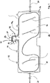
図1は、カーテンエアバッグ10の縦断面を示している。カーテンエアバッグ10は、2つの側壁(そのうちここでは側壁12が示されている)を有しており、それらが端縁領域14内で互いに結合され、例えば互いに縫い合わされている。端縁領域14は、上方のエッジ14aにガスジェネレータを導入するための開口部16と、補強クロス材にカーテンエアバッグ10を配置するための固定フラップ18を有している。さらに、カーテンエアバッグ10は、エアバッグに輪郭を与えるための中間縫い目22と、膨らんだカーテンエアバッグを自動車のサイドウィンドウの前に正しく位置決めするための張りストラップ20を有している。
FIG. 1 shows a longitudinal section of a curtain airbag 10. The curtain airbag 10 has two side walls, of which the side wall 12 is shown, which are joined together in the edge region 14 and are stitched together, for example. The edge region 14 has an opening 16 for introducing the gas generator to the upper edge 14a, and a fixed
開口部領域24は、L字形状に形成されているので、細長いガスジェネレータを使用することができ、そのガスジェネレータは上方のエッジ14aのほぼ中央で部分的に開口部16を通ってエアバッグ内へ延びており、その場合にガスジェネレータはエアバッグの長手方向に対して平行に配置されている。
Since the
L字状の開口部領域24内に、ガス案内部材40が配置されている(図1では、著しく図式的に示されている)。ガス案内部材40は、ポリアミドからなり、開口部領域24内でカーテンエアバッグ10の布地と縫い合わされている。このように縫い合わせることによって、カーテンエアバッグ10の内部のガス案内部材40の位置は、カーテンエアバッグ10を形成する際にすでに一義的に固定されており、後で最終取り付けする際にもはや滑り移動することはない。ガス案内部材の縫込みは、多くの場合において、好ましい結合方法であるが、必要な結合は、接合又は接着によって形成することもできる。
A
ガス案内部材40は、前方の部分42と後方の部分45を有している。前方の部分42の横断面は、U字形状であるので、この前方の部分42は2つの脚を有している。脚の領域において、好ましくは、ガス案内部材と隣接する布地との縫合が行われる。
The
図2は、ガス案内部材40の斜視図である。ここでは、円形の横断面を有する後方の部分45とU字状の横断面を有する前方の部分42をよく認識することができる。組み立てる場合に、ガスジェネレータが後方の部分45を通して挿通されて、係止突出部46に係止される。そのために必要な柔軟性は、スリット47によってもたらされる。図2には、2つの脚42a、bが明らかに示されており、それらの脚を介して縫合が行われる。
FIG. 2 is a perspective view of the
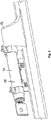
図3と4は、ガスジェネレータ30がカーテンエアバッグ10の開口部16内へ導入されている状態を示している。図から明らかなように、ガスジェネレータ30は全体として細長く、かつ回転対称に組み立てられている。第1の部分32が、エアバッグ内へ突出し、かつ流出開口部33を有しており、それら流出開口部がガス案内部材の前方の部分42によって部分的に包囲されている。さらに、第1の部分32は、切欠き34を有しており、その切欠きがガス案内部材40の係止突出部46と作用結合している。第2の部分35は、エアバッグの外部に位置している。
3 and 4 show a state in which the
エアバッグ内へ突出する第1の部分が大体において細長く形成されている限りにおいて、屈曲されたガスジェネレータを使用することも、考えられる。 It is also conceivable to use a bent gas generator as long as the first part protruding into the airbag is roughly elongated.
図4aは、図4に示すものに対する変形例を示している。他の実施形態におけるように、ガス案内部材40が直接エアバッグ10の布地と結合され、すなわち縫合され、接着され、あるいは接合されている。好ましくは、結合は、ここでも脚42a、42bの領域で行われる。ガス案内部材40の後方の部分45は、ここでは、ブラケット50によってガスジェネレータ30の第2の部分35上に挟持されており、そのブラケットはエアバッグ10もガスジェネレータ30に固定する。それによってガス案内部材40はエアバッグ10ともガスジェネレータ30とも直接結合されており、それによってガスジェネレータ30とエアバッグ10との間にも十分に安定した結合が形成される。
FIG. 4a shows a modification to that shown in FIG. As in other embodiments, the
図5は、図4ないし図4aの断面を切断線A−Aに沿って示している。ここでは、ガス案内部材の前方の部分42が、包囲しているエアバッグ10の布地を流出するガスからどのように保護するか、が非常に良く見える。ガス案内部材の前方の部分が、第1の部分の外壁の所定の領域を包囲しているので、そこにある流出開口部から流出するガスがガス案内部材によって方向変換される。その場合に、脚42a、bがガスをエアバッグ内へ案内する。外壁の下方の部分内にある流出開口部からは、ガスは直接エアバッグ内へ達する。
FIG. 5 shows the cross section of FIGS. 4 to 4a along the section line AA. Here it can be seen very well how the
さらに、縫合領域Nを見ることができ、その中で脚42a、bがエアバッグ10の布地と縫合されている。縫合プロセスを簡略化するために、ガス案内部材の前方の部分は、U字状の断面の代りにΩ状の断面を有することができ、その断面においてオメガの張り出した端部がエアバッグ布地の層に固定される。
Furthermore, a stitched area N can be seen, in which the
ガスジェネレータが係止突出部に嵌り込むことによって、取り付ける人は、ガスジェネレータが軸方向において正しい終端位置にある、という手応えを得る。ガスジェネレータの回転対称の構造に基づいて、カーテンエアバッグに関してガスジェネレータの半径方向の整合が問題にならなくなる。それによってカーテンエアバッグ10へのガスジェネレータ30の取付けないしガスジェネレータ30へのカーテンエアバッグ10の取付けが、極めて容易になる。
By fitting the gas generator into the locking projection, the person who attaches it gets a response that the gas generator is in the correct end position in the axial direction. Based on the rotationally symmetric structure of the gas generator, radial alignment of the gas generator is not a problem with respect to the curtain airbag. Thereby, the attachment of the
図6aと6bは、ガス案内部材40の他の実施例を示している。その場合に図6bは、図6aのガス案内部材の前方の部分42を通る平面Eに沿った断面を示している。この実施例のガス案内部材においては、前方の部分42も後方の部分45もパイプ形状に形成されており、その場合に前方の部分42が長孔48を有しており、その長孔を通して、ガスジェネレータ30から来るガスの少なくとも一部がエアバッグ内へ流入する。長孔48の平面内に、底板49が配置されているので、前方の部分42を通って切断する場合に、図6bに示すように、2つの脚42a、bを有するΩ形状の断面が生じる。安定性を向上させるために、さらに、ステイ50が設けられている。ガス案内部材とエアバッグ布地との結合は、ここでも好ましくは脚42a、bの領域内で行われ、その場合に底板49の全面を利用することができる。
FIGS. 6 a and 6 b show another embodiment of the
Claims (9)
エアバッグ(10)が、端縁領域(14)を介して互いに結合された、布地からなる2つの側壁を有しており、
端縁領域(14)内に開口部(16)が配置されており、前記開口部を通してガスジェネレータ(30)が、ガスジェネレータ(30)の細長く形成された第1の部分(32)の複数の流出開口部(33)がエアバッグの内部に延在するように、延びており、
エアバッグ(10)の内部で開口部(16)の領域(24)内にガス案内部材(40)が配置されており、前記ガス案内部材が開口部の領域にある布地を前記流出開口部(33)から流出する熱いガスから保護する、エアバッグユニットにおいて、
前記ガス案内部材(40)が、プラスチックからなり、脚(42a、42b)を備えたU字状又はΩ形状の横断面を有する前方の部分(42)を有し、かつ布地と縫合、接合又は接着されており、
前記ガス案内部材が、前記前方の部分(42)の脚(42a、42b)を介して前記布地と結合されていることを特徴とするエアバッグユニット。A planarly formed airbag (10) and a gas generator (30) with an outflow opening (33) formed at least partially extending into the airbag;
The airbag (10) has two side walls of fabric joined together via an edge region (14);
An opening (16) is disposed in the edge region (14), through which the gas generator (30) has a plurality of elongated first portions (32) of the gas generator (30). Extending so that the outflow opening (33) extends into the interior of the airbag;
A gas guide member (40) is arranged in the region (24) of the opening (16) inside the airbag (10), and the fabric in which the gas guide member is in the region of the opening is connected to the outflow opening ( 33) In an airbag unit that protects against hot gas flowing out from
Said gas guiding member (40) is made of plastic and has a front part (42) having a U-shaped or Ω-shaped cross section with legs (42a, 42b) and is sewn, joined or bonded to a fabric. Glued,
The airbag unit, wherein the gas guide member is coupled to the fabric through legs (42a, 42b) of the front portion (42).
Applications Claiming Priority (3)
| Application Number | Priority Date | Filing Date | Title |
|---|---|---|---|
| DE102004022740A DE102004022740A1 (en) | 2004-05-07 | 2004-05-07 | Airbag unit |
| DE102004022740.3 | 2004-05-07 | ||
| PCT/EP2005/004865 WO2005110820A1 (en) | 2004-05-07 | 2005-05-04 | Gas bag unit |
Publications (2)
| Publication Number | Publication Date |
|---|---|
| JP2007536154A JP2007536154A (en) | 2007-12-13 |
| JP4908403B2 true JP4908403B2 (en) | 2012-04-04 |
Family
ID=34968895
Family Applications (1)
| Application Number | Title | Priority Date | Filing Date |
|---|---|---|---|
| JP2007512022A Expired - Fee Related JP4908403B2 (en) | 2004-05-07 | 2005-05-04 | Airbag unit |
Country Status (9)
| Country | Link |
|---|---|
| US (1) | US7600778B2 (en) |
| EP (1) | EP1742820B1 (en) |
| JP (1) | JP4908403B2 (en) |
| KR (1) | KR101148174B1 (en) |
| CN (1) | CN100434312C (en) |
| AT (1) | ATE384645T1 (en) |
| DE (2) | DE102004022740A1 (en) |
| ES (1) | ES2303680T3 (en) |
| WO (1) | WO2005110820A1 (en) |
Families Citing this family (16)
| Publication number | Priority date | Publication date | Assignee | Title |
|---|---|---|---|---|
| DE202005019013U1 (en) | 2005-12-01 | 2006-04-20 | Takata-Petri (Ulm) Gmbh | Gas flow distributor for a gas bag module |
| DE202005019014U1 (en) * | 2005-12-01 | 2006-04-20 | Takata-Petri (Ulm) Gmbh | Airbag module for a vehicle restraint system |
| US7641226B2 (en) | 2006-11-01 | 2010-01-05 | Autoliv Development Ab | Side airbag module with an internal guide fin |
| JP2010089547A (en) * | 2008-10-03 | 2010-04-22 | Toyoda Gosei Co Ltd | Head protection airbag device |
| CN102030092A (en) * | 2009-09-30 | 2011-04-27 | 中国船舶重工集团公司第七一○研究所 | High-temperature-resistant underwater recovery gas bag |
| JP5843420B2 (en) * | 2009-10-05 | 2016-01-13 | オートリブ ディベロップメント エービー | Curtain airbag device |
| DE102009045739B4 (en) * | 2009-10-15 | 2013-11-14 | TAKATA Aktiengesellschaft | Diffuser for an airbag device of a vehicle occupant restraint system and airbag device with a diffuser |
| DE102009052565A1 (en) * | 2009-11-10 | 2011-05-12 | GM Global Technology Operations LLC, Detroit | Airbag module for a vehicle |
| US8678440B1 (en) | 2012-12-20 | 2014-03-25 | Autoliv Asp, Inc. | Retractor-lap pretensioner with single micro-gas generator |
| KR101673683B1 (en) * | 2014-10-27 | 2016-11-08 | 현대자동차주식회사 | Assembling apparatus of curtain airbag |
| JP6500274B2 (en) * | 2015-09-01 | 2019-04-17 | 豊田合成株式会社 | Airbag |
| CN109955821A (en) * | 2017-12-25 | 2019-07-02 | 青岛市比亚迪汽车有限公司 | Automotive Safety Air Bags and vehicle with it |
| DE102018124250A1 (en) * | 2018-10-01 | 2020-04-02 | Trw Automotive Gmbh | Airbag module |
| DE102019122990A1 (en) * | 2019-08-27 | 2021-03-04 | Zf Automotive Germany Gmbh | Assembly of a cover cap of a diffuser of a tubular gas generator and a deflector element, tubular gas generator and method for manufacturing a tubular gas generator |
| DE102019122989A1 (en) * | 2019-08-27 | 2021-03-04 | Zf Airbag Germany Gmbh | Deflector for a diffuser of a gas generator, diffuser-deflector assembly with such a deflector, gas generator with such a diffuser-deflector assembly, manufacturing method and assembly method |
| CN113815560B (en) * | 2021-10-27 | 2022-11-11 | 宁波均胜汽车安全系统有限公司 | Air curtain |
Citations (2)
| Publication number | Priority date | Publication date | Assignee | Title |
|---|---|---|---|---|
| JP2595190B2 (en) * | 1992-12-18 | 1997-03-26 | モートン インターナショナル,インコーポレイティド | Diffuser device and airbag module assembly in inflatable restraint system |
| WO2002079008A1 (en) * | 2001-04-02 | 2002-10-10 | Trw Occupant Restraint Systems Gmbh & Co. Kg | Gas bag module for a vehicle occupant restraint system |
Family Cites Families (9)
| Publication number | Priority date | Publication date | Assignee | Title |
|---|---|---|---|---|
| US5172933A (en) * | 1989-10-10 | 1992-12-22 | Ford Motor Company | Air bag diverter |
| JP3178069B2 (en) * | 1992-03-30 | 2001-06-18 | タカタ株式会社 | Inflator mounting structure for passenger airbag device |
| DE9408908U1 (en) | 1994-05-31 | 1994-11-17 | Trw Repa Gmbh | Airbag protection device |
| US6082761A (en) * | 1997-01-24 | 2000-07-04 | Toyoda Gosei Co., Ltd. | Side airbag device |
| JP2000085510A (en) * | 1998-09-14 | 2000-03-28 | Takata Kk | Structure of connecting airbag and inflator |
| US6106006A (en) * | 1999-04-06 | 2000-08-22 | Trw Vehicle Safety Systems Inc. | Vehicle occupant protection apparatus including an inflatable curtain and a housing containing the curtain |
| JP4005321B2 (en) * | 2001-02-05 | 2007-11-07 | トヨタ自動車株式会社 | Head protection airbag device |
| GB2378924B (en) * | 2001-08-22 | 2004-10-20 | Autoliv Dev | Improvements in or relating to an air-bag |
| GB2397806B (en) * | 2003-01-31 | 2006-01-04 | Autoliv Dev | Improvements in or relating to an air-bag |
-
2004
- 2004-05-07 DE DE102004022740A patent/DE102004022740A1/en not_active Withdrawn
-
2005
- 2005-05-04 JP JP2007512022A patent/JP4908403B2/en not_active Expired - Fee Related
- 2005-05-04 EP EP05746630A patent/EP1742820B1/en not_active Not-in-force
- 2005-05-04 KR KR1020067023324A patent/KR101148174B1/en not_active IP Right Cessation
- 2005-05-04 CN CNB200580014606XA patent/CN100434312C/en not_active Expired - Fee Related
- 2005-05-04 ES ES05746630T patent/ES2303680T3/en active Active
- 2005-05-04 US US11/579,856 patent/US7600778B2/en not_active Expired - Fee Related
- 2005-05-04 DE DE502005002669T patent/DE502005002669D1/en active Active
- 2005-05-04 WO PCT/EP2005/004865 patent/WO2005110820A1/en active IP Right Grant
- 2005-05-04 AT AT05746630T patent/ATE384645T1/en not_active IP Right Cessation
Patent Citations (2)
| Publication number | Priority date | Publication date | Assignee | Title |
|---|---|---|---|---|
| JP2595190B2 (en) * | 1992-12-18 | 1997-03-26 | モートン インターナショナル,インコーポレイティド | Diffuser device and airbag module assembly in inflatable restraint system |
| WO2002079008A1 (en) * | 2001-04-02 | 2002-10-10 | Trw Occupant Restraint Systems Gmbh & Co. Kg | Gas bag module for a vehicle occupant restraint system |
Also Published As
| Publication number | Publication date |
|---|---|
| KR101148174B1 (en) | 2012-05-24 |
| JP2007536154A (en) | 2007-12-13 |
| CN100434312C (en) | 2008-11-19 |
| ES2303680T3 (en) | 2008-08-16 |
| DE502005002669D1 (en) | 2008-03-13 |
| US7600778B2 (en) | 2009-10-13 |
| WO2005110820A1 (en) | 2005-11-24 |
| US20070216145A1 (en) | 2007-09-20 |
| EP1742820B1 (en) | 2008-01-23 |
| ATE384645T1 (en) | 2008-02-15 |
| DE102004022740A1 (en) | 2005-12-01 |
| KR20070007183A (en) | 2007-01-12 |
| EP1742820A1 (en) | 2007-01-17 |
| CN1953890A (en) | 2007-04-25 |
Similar Documents
| Publication | Publication Date | Title |
|---|---|---|
| JP4908403B2 (en) | Airbag unit | |
| EP1286867B1 (en) | Side airbag curtain module | |
| US7891700B2 (en) | Airbag for knee protection | |
| US20050073134A1 (en) | Knee protection airbag device | |
| US7168735B2 (en) | Airbag apparatus | |
| JP2004314706A (en) | Occupant restraint device | |
| JP2005082025A (en) | Air bag, and air bag assembly | |
| JP2009056980A (en) | Lapping sheet | |
| JP2018167796A (en) | Air bag device | |
| JP2018167793A (en) | Air bag device | |
| JP2011502877A (en) | AIRBAG HAVING FILLING UNIT, AIRBAG AND AIRBAG DEVICE HAVING GAS GENERATOR | |
| JP2010137615A (en) | Side airbag device | |
| JP2011502877A5 (en) | ||
| JP2018167794A (en) | Air bag device | |
| JP6500274B2 (en) | Airbag | |
| CN109591750A (en) | Airbag apparatus | |
| JP2007008318A (en) | Side airbag | |
| JP2009132245A (en) | Air bag device | |
| JP6922803B2 (en) | Airbag device | |
| JP2021127005A (en) | Head protection airbag device | |
| JP4063168B2 (en) | Knee protection airbag | |
| JP2005096625A (en) | Knee protection airbag apparatus | |
| JP2006232275A (en) | Occupant restraint system | |
| JP5768707B2 (en) | Head protection airbag device | |
| JP6200230B2 (en) | Airbag device |
Legal Events
| Date | Code | Title | Description |
|---|---|---|---|
| A621 | Written request for application examination |
Free format text: JAPANESE INTERMEDIATE CODE: A621 Effective date: 20080219 |
|
| A977 | Report on retrieval |
Free format text: JAPANESE INTERMEDIATE CODE: A971007 Effective date: 20100812 |
|
| A131 | Notification of reasons for refusal |
Free format text: JAPANESE INTERMEDIATE CODE: A131 Effective date: 20100817 |
|
| A601 | Written request for extension of time |
Free format text: JAPANESE INTERMEDIATE CODE: A601 Effective date: 20101116 |
|
| A602 | Written permission of extension of time |
Free format text: JAPANESE INTERMEDIATE CODE: A602 Effective date: 20101124 |
|
| A521 | Request for written amendment filed |
Free format text: JAPANESE INTERMEDIATE CODE: A523 Effective date: 20110118 |
|
| A131 | Notification of reasons for refusal |
Free format text: JAPANESE INTERMEDIATE CODE: A131 Effective date: 20110823 |
|
| A521 | Request for written amendment filed |
Free format text: JAPANESE INTERMEDIATE CODE: A523 Effective date: 20111118 |
|
| TRDD | Decision of grant or rejection written | ||
| A01 | Written decision to grant a patent or to grant a registration (utility model) |
Free format text: JAPANESE INTERMEDIATE CODE: A01 Effective date: 20111213 |
|
| A01 | Written decision to grant a patent or to grant a registration (utility model) |
Free format text: JAPANESE INTERMEDIATE CODE: A01 |
|
| A61 | First payment of annual fees (during grant procedure) |
Free format text: JAPANESE INTERMEDIATE CODE: A61 Effective date: 20120112 |
|
| FPAY | Renewal fee payment (event date is renewal date of database) |
Free format text: PAYMENT UNTIL: 20150120 Year of fee payment: 3 |
|
| R150 | Certificate of patent or registration of utility model |
Free format text: JAPANESE INTERMEDIATE CODE: R150 |
|
| R250 | Receipt of annual fees |
Free format text: JAPANESE INTERMEDIATE CODE: R250 |
|
| R250 | Receipt of annual fees |
Free format text: JAPANESE INTERMEDIATE CODE: R250 |
|
| LAPS | Cancellation because of no payment of annual fees |