JP4907015B2 - Multipurpose detector - Google Patents
Multipurpose detector Download PDFInfo
- Publication number
- JP4907015B2 JP4907015B2 JP2001221163A JP2001221163A JP4907015B2 JP 4907015 B2 JP4907015 B2 JP 4907015B2 JP 2001221163 A JP2001221163 A JP 2001221163A JP 2001221163 A JP2001221163 A JP 2001221163A JP 4907015 B2 JP4907015 B2 JP 4907015B2
- Authority
- JP
- Japan
- Prior art keywords
- detector
- filter
- array
- radiation
- signal processing
- Prior art date
- Legal status (The legal status is an assumption and is not a legal conclusion. Google has not performed a legal analysis and makes no representation as to the accuracy of the status listed.)
- Expired - Fee Related
Links
- 238000001514 detection method Methods 0.000 claims abstract description 12
- 230000005855 radiation Effects 0.000 claims description 22
- 230000008859 change Effects 0.000 claims description 7
- 230000004044 response Effects 0.000 claims description 7
- 238000001914 filtration Methods 0.000 claims description 6
- 230000003595 spectral effect Effects 0.000 abstract description 7
- 230000003287 optical effect Effects 0.000 abstract description 2
- 238000001228 spectrum Methods 0.000 description 11
- 230000000694 effects Effects 0.000 description 7
- 229910052732 germanium Inorganic materials 0.000 description 6
- GNPVGFCGXDBREM-UHFFFAOYSA-N germanium atom Chemical compound [Ge] GNPVGFCGXDBREM-UHFFFAOYSA-N 0.000 description 6
- 230000007246 mechanism Effects 0.000 description 6
- 229910052594 sapphire Inorganic materials 0.000 description 6
- 239000010980 sapphire Substances 0.000 description 6
- 238000012544 monitoring process Methods 0.000 description 4
- 238000004458 analytical method Methods 0.000 description 3
- 239000000463 material Substances 0.000 description 3
- CURLTUGMZLYLDI-UHFFFAOYSA-N Carbon dioxide Chemical compound O=C=O CURLTUGMZLYLDI-UHFFFAOYSA-N 0.000 description 2
- 241000282412 Homo Species 0.000 description 1
- 241001349296 Tragia volubilis Species 0.000 description 1
- 238000003491 array Methods 0.000 description 1
- 229910002092 carbon dioxide Inorganic materials 0.000 description 1
- 239000001569 carbon dioxide Substances 0.000 description 1
- 239000011248 coating agent Substances 0.000 description 1
- 238000000576 coating method Methods 0.000 description 1
- 230000007613 environmental effect Effects 0.000 description 1
- 238000007689 inspection Methods 0.000 description 1
- 238000000034 method Methods 0.000 description 1
- 230000008569 process Effects 0.000 description 1
- 238000003672 processing method Methods 0.000 description 1
- 238000011895 specific detection Methods 0.000 description 1
Images


Classifications
-
- G—PHYSICS
- G01—MEASURING; TESTING
- G01J—MEASUREMENT OF INTENSITY, VELOCITY, SPECTRAL CONTENT, POLARISATION, PHASE OR PULSE CHARACTERISTICS OF INFRARED, VISIBLE OR ULTRAVIOLET LIGHT; COLORIMETRY; RADIATION PYROMETRY
- G01J5/00—Radiation pyrometry, e.g. infrared or optical thermometry
- G01J5/60—Radiation pyrometry, e.g. infrared or optical thermometry using determination of colour temperature
- G01J5/602—Radiation pyrometry, e.g. infrared or optical thermometry using determination of colour temperature using selective, monochromatic or bandpass filtering
-
- G—PHYSICS
- G08—SIGNALLING
- G08B—SIGNALLING OR CALLING SYSTEMS; ORDER TELEGRAPHS; ALARM SYSTEMS
- G08B13/00—Burglar, theft or intruder alarms
- G08B13/18—Actuation by interference with heat, light, or radiation of shorter wavelength; Actuation by intruding sources of heat, light, or radiation of shorter wavelength
- G08B13/189—Actuation by interference with heat, light, or radiation of shorter wavelength; Actuation by intruding sources of heat, light, or radiation of shorter wavelength using passive radiation detection systems
- G08B13/19—Actuation by interference with heat, light, or radiation of shorter wavelength; Actuation by intruding sources of heat, light, or radiation of shorter wavelength using passive radiation detection systems using infrared-radiation detection systems
-
- G—PHYSICS
- G08—SIGNALLING
- G08B—SIGNALLING OR CALLING SYSTEMS; ORDER TELEGRAPHS; ALARM SYSTEMS
- G08B17/00—Fire alarms; Alarms responsive to explosion
- G08B17/12—Actuation by presence of radiation or particles, e.g. of infrared radiation or of ions
Landscapes
- Physics & Mathematics (AREA)
- General Physics & Mathematics (AREA)
- Spectroscopy & Molecular Physics (AREA)
- Business, Economics & Management (AREA)
- Emergency Management (AREA)
- Photometry And Measurement Of Optical Pulse Characteristics (AREA)
- Fire-Detection Mechanisms (AREA)
- Radiation Pyrometers (AREA)
- Analysing Materials By The Use Of Radiation (AREA)
- Eye Examination Apparatus (AREA)
- Interface Circuits In Exchanges (AREA)
Abstract
Description
【0001】
【発明の属する技術分野】
本発明は、いくつかの異なる種類の事象を検出するための多目的検出器に関する。
【0002】
【従来の技術】
4.3μmの波長に中心がある挟帯域フィルタを使用して高温二酸化炭素からの放射を検出することで、受動的な赤外線検出器を炎の検出に使用することができることは既知である。検出器素子のアレイを使用することにより、炎の大きさおよび位置のような追加の情報を導き出すことができる空間的な情報を得ることができる。
【0003】
さらに、スペクトルの異なる部分からの信号を解析することで、炎検出器の性能を向上させることができる。一般に、スペクトルの適切な部分に対して敏感なフィルタを各々が持っている最大3個の別個の検出器を使用して、これは実現できる。
【0004】
受動赤外線検出器に5.5μm長波通過フィルタを取り付けた時に、その受動赤外線検出器は人を検出するために使用できることも既知である。上に述べた炎検出器の場合のように、検出器素子のアレイを使用して、視野内の人の数および位置のような追加の情報を得ることを可能にする空間情報を得ることができる。さらに、各場合の特定の検出要件を実現するように異なるアルゴリズムを使用して、例えばドア開け器、侵入者検出器または活動監視器のようなある決まった用途の範囲で、人の検出を使用することができる。
【0005】
【発明が解決しようとする課題】
火と人の両方を検出することができる検出器に長い間関心が持たれていたが、このことは従来型検出器の各々の光学的仕様によって非現実的なものになり、一般に、各場合に異なる検出器が使用されている。
【0006】
【課題を解決するための手段】
本発明は、
受動赤外線検出器素子のアレイと、
ある光景からの広帯域放射を上記アレイに集束させるための光収集手段と、
上記検出器素子からの信号を処理するための手段と、
上記広帯域内でより狭い範囲の放射だけが上記検出器素子に達することができるように配設されたフィルタ処理手段と、を備え、
上記フィルタ処理手段は、異なる範囲の放射が上記検出器素子に達することができるように上記信号処理手段からの制御信号に応答して選択可能な2以上のフィルタ構成を実現し、
上記制御信号は、上記アレイの上記素子から受け取られた信号に依存して、上記信号処理手段により生成される、
ことを特徴とする多目的検出器を提供する。
【0007】
好ましい実施態様では、異なる範囲の波長を選択すると、スペクトルの異なる部分を調べることにより、性能の利点が得られるようになる。この場合、多数のアレイを使用する必要はないが、位置合わせに関して固有のコスト面の不利および困難を伴う。
アレイからの信号を適切に処理することで、アレイからの空間的な情報と共に選択可能なスペクトル情報を使用して、従来のアレイをベースにした検出器と比較して追加の機能を実現することができる。例えば、空間的な情報とスペクトル情報の組合せを使用して、炎を発生しない火を検出することができる。
【0008】
さらに、好ましい実施態様では、各場合の適切な信号処理と検出アルゴリズムと共に異なるフィルタ構成を選択することで、単一の検出器を使用して、人と火の存在のような全く異なる事象を検出することができる。そのような装置は、特定の時に、火検出器としてか人検出器としてかいずれかで動作するように選択できる。または、そうではなくて、火と人の両方を絶え間なく走査するように動作することができる。他の実施態様では、空間的な情報を使用して、例えば火および/または人の存在のような、光景の特定の場所に許容できる事象であるか許容できない事象であるかを判別することができる。
【0009】
検出器アレイ自体は、一般に、別個の受動赤外線検出器素子の2次元または実質的に2次元のアレイで構成され、その検出器素子は焦電検出器素子で良い。光収集手段によってそのアレイに通過することのできる広帯域放射は、一般に、使用されている検出器素子が検出できる波長の範囲を少なくとも含む。受動赤外線検出器の場合、この広帯域放射は一般に2μmから20μmの波長範囲内にある。
【0010】
特に好ましい実施態様では、信号処理手段で生成された制御信号に応答して、フィルタ構成を選択することができる。この信号によって、利用可能なフィルタ構成の実現を順次に行うことができる。または、その代わりに、この信号によって、その光景内で起こっている事象についてより多くの情報を判断できるようにするか、または、そのような事象の種類を確認することができるようにする特定のフィルタ構成が選択されるようにしても良い。
【0011】
ここで本発明の実施形態を、単なる例として、添付の図面を参照して説明する。
【0012】
【発明の実施の形態】
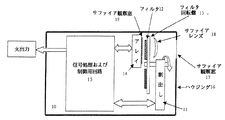
図1を参照すると、火検出器10が示されており、その火検出器では、回転可能な回転盤13に取り付けられた異なるスペクトルフィルタ12を検出器素子のアレイ14の正面に持ってくるために、割出し機構11が使用される。検出器10はさらに信号処理および制御用ユニット15を含み、その信号処理および制御用ユニット15は、検出器アレイ14から信号を受け取り、さらにまた、検出器アレイから受け取られた信号に依存して、割出し機構11を制御することが好ましい。そのユニット15は、また、火の検出に関係する情報を含む信号を出力する。この信号は、その光景内に火があることをただ単に示すこともあり、また、例えば、その光景内の火の位置または火の広がりに関する情報をさらに含むこともある。
【0013】
検出器は、サファイアの観察窓17を有するハウジング16内に閉囲されており、その観察窓17によって、光景からの放射がサファイアのレンズ18および選択されたフィルタ12を介して検出器の中に入り、さらにアレイ14に達することができるようになる。窓17は、関心のあるスペクトルの部分の放射の伝播に影響を及ぼすことなしに環境保護を実現し、また、同様な窓19はアレイ自体を保護するために設けられる。
【0014】
レンズ18は、観察窓17と選択されたフィルタ12の間に位置付けされるが、同様に、フィルタとアレイの間に位置付けされる可能性もある。レンズは、適切な視野を与えるように位置付けされ、さらにレンズの材料は、必要な範囲の波長の放射がアレイに達することができるように選ばれる。この場合に、レンズは観察窓17と同じ材料、すなわちサファイアで作られる。
【0015】
この実施形態では、スペクトルフィルタは、アレイの前に適切なフィルタを位置付けする割出し機構11で選ばれる。図1の実施形態で使用された回転可能な回転盤は、フィルタを位置付けするための他の適当な手段で置き換えることができる。その手段は、例えば、フィルタを変えるために往復運動を使用する可能性がある。
【0016】
スペクトルの関係する部分での活動をより詳細に観察し解析することができるように、様々なフィルタが選ばれる。他の発展として、図2は図1の検出器に類似した検出器20を示し、その検出器20では、火の存在以外の事象を検出し解析することができるようにフィルタが選ばれる。(図2と3において、図1の参照数字と同じ参照数字は同じ構成要素を示し、その構成要素はもう説明しない)。図2の実施形態で、窓27、29は広帯域の窓であり、レンズ28はその窓に似た材料で作られた広帯域レンズである。レンズ28は、反射防止被膜で覆われたゲルマニウムで形成しても良い。割出し機構は少なくとも3つの位置を有する。すなわち、5.5μm長波通過フィルタ、4.3μm帯域フィルタ、および全ての波長の放射がアレイの見る窓27、29およびレンズ28を通過することができるようにする開いた位置を有する。これらの位置の最初の2つだけを図2に示す。
【0017】
図2の実施形態で使用される特定のフィルタによって、検出器を火検出器と人検出器の両方として使用することができるようになる。それに対応して、図示するように、これらの異なる機能に対して異なる出力が与えられる。さらに、侵入者検出と活動監視の各機能に適切な異なる信号処理方法を使用して、同じ5.5μmのフィルタを使用する時でも、人検出器の機能を、侵入者検出と活動監視にさらに分けることができる。その時に、図2に示すように、侵入者検出器機能と活動監視機能に対して、別個の出力が与えられる。
【0018】
図2の検出器の一般的な動作モードを次に説明する。通常動作では、割出し機構は「広帯域」の位置にあるので、アレイは、スペクトルの炎検出部分か人検出部分内への入射放射のあらゆる変化を検出することができる。放射の全ての変化が、信号処理で解析され、この変化の最も可能性のある原因について判断がなされ、さらに適切なスペクトルフィルタがアレイの前に移される。判断決定処理には、スペクトルの他の部分で検査を行う必要がある。この場合に、割出し機構は所定の位置に他のフィルタを持ってくるために使用され、結果として得られた信号が処理されて、最初の解析の判断が確認されるか却下される。
【0019】
例えば、広帯域の位置では、炎のちらつきを表す特徴が光景内に検出されることがある。これに応答して、制御ユニットは4.3μmフィルタを選択し、検出されたちらつきの相対的な振幅を検査して、炎の検出に関連したスペクトルの部分でそのちらつきが本当に起きているかどうか確認することがある。他のフィルタを試みるために選んで、その出所が炎であることを確認するか、または検出された信号の可能性の高い原因を分離することがある。
【0020】
同様に、人の存在を表す信号が広帯域の位置で検出されることがある。この最初の解析は、広帯域位置で検出される特徴信号の振幅および空間情報に基づいて行われることがあり、さらに5.5μmフィルタを通した時の信号の相対的な振幅を調べて確認されることがある。
【0021】
また、詳細な「最初の解析」を行う必要がない場合があり、広帯域位置での顕著な活動の検出に応答して、検出器は様々なフィルタの範囲にわたってただ単に循環させ始めることがある。ことによると特定の期間の間、所定の閾値より上にある検出器素子からの信号として、または異なる素子から受け取られるそのような信号の特定の数として、顕著な活動が定義されることがある。様々なフィルタにわたって循環するこのシステムを使用して、スペクトルの様々な位置で検出された信号の相対的な振幅を調べて、その光景内で起きている事象の可能性の高い性質を決定しても良い。他の情報、例えば空間情報をも考慮に入れると良い。いったん事象の満足な識別が確立されると、その事象をより詳細に監視するために、フィルタの繰返しを止めて、特定のフィルタを選択しても良い。
【0022】
ある特定の用途では、代わりに、スペクトルの様々な部分から連続的な情報を得るために、フィルタを絶え間なく循環させることが望ましい可能性がある。または、絶え間なくフィルタを循環させるが、特定のフィルタの選択に対応する特定の時間に受け取られた信号だけを解析することが望ましい場合がある。
【0023】
いくつかの用途では、用途の間で視野を変更することが好ましい場合がある。これは図3に示すように達成することができる。その図3では、固定レンズが取り除かれて、各用途に適合するレンズ38、39がフィルタ回転盤13に取り付けられている。図4は、4つの位置を有するフィルタ回転盤43を示す。3つの位置にはフィルタ/レンズの組合せ45、46、47が取り付けられ、第4の位置には広帯域レンズ48だけが取り付けられている。第4の位置は、図2の実施形態のフィルタ回転盤の開いた位置に等しく、この配置のデフォルト位置である。
【0024】
図4のフィルタ回転盤内のフィルタ/レンズの組合せは、長波通過フィルタを有する広角被覆ゲルマニウム・レンズ45、4.3μmフィルタを有する広角サファイア・レンズ46、および長波通過フィルタを有する狭角被覆ゲルマニウムレンズ47である。
【0025】
本発明で使用される適切なフィルタ構成を形成するためには、どのような組合せのフィルタをも利用できることを理解されたい。またはフィルタ処理手段は、2以上の異なる範囲の放射を伝送するように動作可能な単一の素子を備えることとしても良い。例えば、炎検出で使用されることが多い2つの監視帯域に対応するスペクトルの2つの部分にわたって帯域通過を実現する単一フィルタを使用しても良い。
【0026】
一般に、炎の存在を検出する時に、放射の通過は、2.5μmから6.0μmの範囲の波長に制限され、ことによると3.5μmと4.5μmの間の波長に制限される。人を検出する時には、5.5μmと15μmの間の波長に制限される。
【図面の簡単な説明】
【図1】異なるフィルタ構成の選択を有する火検出器を模式的に示す。
【図2】結合された火および人検出器を示す。
【図3】結合された火および人検出器の他の実施形態を示す。
【図4】図3の実施形態で使用されたフィルタとレンズの配置を詳細に示す。
【符号の説明】
11 割出し
12 フィルタ
13,43 フィルタ回転盤
14 アレイ
15 信号処理および制御用回路
16 ハウジング
17,19 サファイア観察窓
18 サファアレンズ
27,29 広帯域窓
28 広帯域レンズ
38,39 レンズ
45 広角被覆ゲルマニウムレンズおよび長波通過フィルタ
46 広角サファイアレンズおよび4.3ミクロンフィルタ
47 狭角被覆ゲルマニウムレンズおよび長波通過フィルタ
48 広帯域被覆ゲルマニウムレンズ[0001]
BACKGROUND OF THE INVENTION
The present invention relates to a multi-purpose detector for detecting several different types of events.
[0002]
[Prior art]
It is known that passive infrared detectors can be used for flame detection by detecting radiation from hot carbon dioxide using a narrowband filter centered at a wavelength of 4.3 μm. By using an array of detector elements, spatial information can be obtained from which additional information such as flame size and position can be derived.
[0003]
Furthermore, the performance of the flame detector can be improved by analyzing signals from different parts of the spectrum. In general, this can be achieved using up to three separate detectors, each having a filter that is sensitive to the appropriate part of the spectrum.
[0004]
It is also known that when a 5.5 μm long wave pass filter is attached to a passive infrared detector, the passive infrared detector can be used to detect a person. As in the case of the flame detector described above, an array of detector elements can be used to obtain spatial information that allows obtaining additional information such as the number and position of people in the field of view. it can. In addition, use human detection in a range of certain applications, such as door openers, intruder detectors or activity monitors, using different algorithms to achieve specific detection requirements in each case can do.
[0005]
[Problems to be solved by the invention]
There has long been interest in detectors that can detect both fire and humans, but this has become impractical due to the optical specifications of each of the conventional detectors, and in general, in each case Different detectors are used.
[0006]
[Means for Solving the Problems]
The present invention
An array of passive infrared detector elements;
Light collection means for focusing broadband radiation from a scene onto the array;
Means for processing the signal from the detector element;
Filtering means arranged so that only a narrower range of radiation within the broadband can reach the detector element;
The filtering means implements two or more filter configurations that are selectable in response to a control signal from the signal processing means so that different ranges of radiation can reach the detector elements;
The control signal is generated by the signal processing means in dependence on a signal received from the element of the array;
A multi-purpose detector is provided.
[0007]
In the preferred embodiment , selecting a different range of wavelengths will result in performance benefits by examining different portions of the spectrum. In this case, it is not necessary to use a large number of arrays, but with the inherent cost disadvantages and difficulties associated with alignment.
Appropriate processing of signals from the array, using selectable spectral information along with spatial information from the array to provide additional functionality compared to traditional array-based detectors Can do. For example, a combination of spatial information and spectral information can be used to detect a fire that does not generate a flame.
[0008]
In addition, the preferred embodiment uses a single detector to detect completely different events, such as the presence of a person and fire, by selecting different filter configurations with appropriate signal processing and detection algorithms in each case. can do. Such a device can be selected to operate either as a fire detector or as a human detector at a particular time. Or, rather, it can operate to continually scan both fire and people. In other embodiments, spatial information may be used to determine whether an event is acceptable or unacceptable for a particular location in the scene, such as fire and / or human presence. it can.
[0009]
The detector array itself generally consists of a two-dimensional or substantially two-dimensional array of separate passive infrared detector elements, which may be pyroelectric detector elements. Broadband radiation that can pass through the array by the light collection means generally includes at least a range of wavelengths that can be detected by the detector elements being used. For passive infrared detectors, this broadband radiation is generally in the wavelength range of 2 μm to 20 μm.
[0010]
In a particularly preferred embodiment, the filter configuration can be selected in response to a control signal generated by the signal processing means. With this signal, the available filter configurations can be realized sequentially. Or, instead, this signal allows you to determine more information about what is happening in the scene, or to identify the type of such event A filter configuration may be selected.
[0011]
Embodiments of the present invention will now be described, by way of example only, with reference to the accompanying drawings.
[0012]
DETAILED DESCRIPTION OF THE INVENTION
Referring to FIG. 1, a
[0013]
The detector is enclosed in a housing 16 having a
[0014]
The
[0015]
In this embodiment, the spectral filter is selected with an
[0016]
Various filters are chosen so that activity in the relevant part of the spectrum can be observed and analyzed in more detail. As another development, FIG. 2 shows a
[0017]
The particular filter used in the embodiment of FIG. 2 allows the detector to be used as both a fire detector and a human detector. Correspondingly, different outputs are provided for these different functions, as shown. Furthermore, using different signal processing methods appropriate for each function of intruder detection and activity monitoring, even when using the same 5.5 μm filter, the function of the human detector is further improved for intruder detection and activity monitoring. Can be divided. At that time, as shown in FIG. 2, separate outputs are provided for the intruder detector function and the activity monitoring function.
[0018]
The general operating mode of the detector of FIG. 2 will now be described. In normal operation, the indexing mechanism is in a “broadband” position so that the array can detect any change in incident radiation into the flame detection or human detection portion of the spectrum. All changes in radiation are analyzed in signal processing, a determination is made as to the most likely cause of this change, and an appropriate spectral filter is moved in front of the array. The decision determination process requires inspection at other parts of the spectrum. In this case, the indexing mechanism is used to bring another filter in place and the resulting signal is processed to confirm or reject the initial analysis decision.
[0019]
For example, in a wideband position, a feature representing flame flicker may be detected in the scene. In response, the control unit selects a 4.3 μm filter and examines the relative amplitude of the detected flicker to see if the flicker is really occurring in the portion of the spectrum associated with flame detection. There are things to do. Other filters may be chosen to try and confirm that the source is a flame or isolate a likely cause of the detected signal.
[0020]
Similarly, a signal representing the presence of a person may be detected at a broadband position. This initial analysis may be based on the amplitude and spatial information of the feature signal detected at a wideband position, and is further confirmed by examining the relative amplitude of the signal as it passes through the 5.5 μm filter. Sometimes.
[0021]
Also, it may not be necessary to perform a detailed “first analysis”, and in response to detecting significant activity at a broadband location, the detector may simply begin to cycle through various filter ranges. Significant activity may be defined as signals from detector elements that are above a predetermined threshold, or as a specific number of such signals received from different elements, possibly for a certain period of time. . Using this system circulating across various filters, the relative amplitudes of the signals detected at various positions in the spectrum are examined to determine the likely nature of events occurring in the scene. Also good. Other information, such as spatial information, may be taken into account. Once a satisfactory identification of an event is established, the filter may stop repeating and a particular filter may be selected in order to monitor the event in more detail.
[0022]
In certain applications, it may instead be desirable to cycle the filter continuously to obtain continuous information from different parts of the spectrum. Alternatively, it may be desirable to continually circulate the filter, but only analyze the signal received at a particular time corresponding to a particular filter selection.
[0023]
In some applications it may be preferable to change the field of view between applications. This can be achieved as shown in FIG. In FIG. 3, the fixed lens is removed, and lenses 38 and 39 suitable for each application are attached to the filter rotating plate 13. FIG. 4 shows a filter turntable 43 having four positions. Filter /
[0024]
The filter / lens combination in the filter turntable of FIG. 4 consists of a wide angle coated
[0025]
It should be understood that any combination of filters can be utilized to form a suitable filter configuration for use with the present invention. Alternatively, the filtering means may comprise a single element operable to transmit two or more different ranges of radiation. For example, a single filter may be used that provides bandpass over two parts of the spectrum corresponding to the two monitoring bands often used in flame detection.
[0026]
In general, when detecting the presence of a flame, the passage of radiation is limited to wavelengths in the range of 2.5 μm to 6.0 μm, possibly limited to wavelengths between 3.5 μm and 4.5 μm. When detecting a person, the wavelength is limited to between 5.5 μm and 15 μm.
[Brief description of the drawings]
FIG. 1 schematically shows a fire detector with a selection of different filter configurations.
FIG. 2 shows a combined fire and human detector.
FIG. 3 illustrates another embodiment of a combined fire and human detector.
4 shows in detail the arrangement of filters and lenses used in the embodiment of FIG.
[Explanation of symbols]
11 Index 12 Filter 13, 43
Claims (11)
光景からの広帯域放射を前記受動赤外線検出器素子のアレイ上に集束させるための光収集手段(18;28;38;39;45−48)と、
前記受動赤外線検出器素子からの信号を処理するための信号処理手段(15)
と、
フィルタ処理手段(12)と、を備え、
前記フィルタ処理手段(11−13;43)は、互いに異なる前記広帯域内のより狭い範囲の放射だけが前記受動赤外線検出器素子のアレイに達することができるように前記信号処理手段からの制御信号に応答して選択可能とされた2以上のフィルタ構成と、広帯域の放射が前記受動赤外線検出器素子のアレイに達する通常動作とを実現し、
前記信号処理手段(15)は、前記通常動作において前記受動赤外線検出器素子のアレイによって検出された放射中の変化を解析し、放射中の前記変化の最も可能性のある原因を決定し、決定された前記変化の原因に基づいてフィルタ構成が選択されるように制御信号を生成する、
ことを特徴とする多目的検出器。An array (14) of passive infrared detector elements;
Light collection means (18; 28; 38; 39; 45-48) for focusing broadband radiation from a scene onto the array of passive infrared detector elements;
Signal processing means (15) for processing signals from the passive infrared detector element
When,
Filter processing means (12),
Said filtering means (11-13; 43), the control signal from the signal processing means so that only radiation of a narrower range of different said wideband each other reaches the array of passive infrared detector elements It realized 2 and more filter configurations is possible to select in response, and a normal operation broadband radiation reaches said array of passive infrared detector elements,
The signal processing means (15) analyzes the change in emission detected by the array of passive infrared detector elements in the normal operation to determine and determine the most likely cause of the change in emission. generating a control signal to the filter configuration is selected based on the cause of the change that is,
Multipurpose detector characterized by that.
Applications Claiming Priority (2)
| Application Number | Priority Date | Filing Date | Title |
|---|---|---|---|
| GB0018045.5 | 2000-07-21 | ||
| GB0018045A GB2365120B (en) | 2000-07-21 | 2000-07-21 | Multipurpose detector |
Publications (3)
| Publication Number | Publication Date |
|---|---|
| JP2002116084A JP2002116084A (en) | 2002-04-19 |
| JP2002116084A5 JP2002116084A5 (en) | 2008-09-04 |
| JP4907015B2 true JP4907015B2 (en) | 2012-03-28 |
Family
ID=9896167
Family Applications (1)
| Application Number | Title | Priority Date | Filing Date |
|---|---|---|---|
| JP2001221163A Expired - Fee Related JP4907015B2 (en) | 2000-07-21 | 2001-07-23 | Multipurpose detector |
Country Status (6)
| Country | Link |
|---|---|
| US (1) | US6653939B2 (en) |
| EP (1) | EP1174836B1 (en) |
| JP (1) | JP4907015B2 (en) |
| AT (1) | ATE438167T1 (en) |
| DE (1) | DE60139368D1 (en) |
| GB (1) | GB2365120B (en) |
Families Citing this family (18)
| Publication number | Priority date | Publication date | Assignee | Title |
|---|---|---|---|---|
| GB2373389B (en) * | 2001-03-12 | 2003-03-12 | Infrared Integrated Syst Ltd | A method of multiplexing column amplifiers in a resistive bolometer array |
| US7333129B2 (en) * | 2001-09-21 | 2008-02-19 | Rosemount Aerospace Inc. | Fire detection system |
| US6909495B2 (en) | 2002-08-13 | 2005-06-21 | Diamond Power International, Inc. | Emissivity probe |
| JP2006518464A (en) * | 2003-01-31 | 2006-08-10 | マイクロン インフラレッド インコーポレイテッド | Infrared imaging device |
| US7348562B2 (en) | 2004-02-02 | 2008-03-25 | Mikron Infrared, Inc. | Method for adapting an existing thermal imaging device |
| EP1653203A1 (en) * | 2004-10-20 | 2006-05-03 | Acterna Germany GmbH | Optical power measuring apparatus |
| US7639843B2 (en) * | 2006-07-19 | 2009-12-29 | Fluke Corporation | Legend including transparent zone |
| US8386951B2 (en) * | 2006-09-29 | 2013-02-26 | Fluke Corporation | Display adjustment features |
| US8648307B2 (en) * | 2007-06-08 | 2014-02-11 | Panasonic Corporation | Infrared ray detector |
| US8227756B2 (en) * | 2009-06-24 | 2012-07-24 | Knowflame, Inc. | Apparatus for flame discrimination utilizing long wavelength pass filters and related method |
| US9121760B2 (en) * | 2010-01-27 | 2015-09-01 | Ci Systems Ltd. | Room-temperature filtering for passive infrared imaging |
| US9082275B2 (en) * | 2011-02-18 | 2015-07-14 | Lyndon Frederick Baker | Alarm device for alerting hazardous conditions |
| US9250135B2 (en) | 2011-03-16 | 2016-02-02 | Honeywell International Inc. | MWIR sensor for flame detection |
| US8841617B2 (en) * | 2011-07-05 | 2014-09-23 | Honeywell International Inc. | Flame detectors and methods of detecting flames |
| US9587987B2 (en) * | 2012-03-12 | 2017-03-07 | Honeywell International Inc. | Method and device for detection of multiple flame types |
| CN103630245A (en) * | 2013-12-07 | 2014-03-12 | 哈尔滨威克科技有限公司 | Multielement linear array high-speed heat distribution imaging detector |
| US10186124B1 (en) | 2017-10-26 | 2019-01-22 | Scott Charles Mullins | Behavioral intrusion detection system |
| AU2020272775A1 (en) | 2019-04-10 | 2021-11-18 | Raptor Vision, Llc | Monitoring systems |
Family Cites Families (18)
| Publication number | Priority date | Publication date | Assignee | Title |
|---|---|---|---|---|
| DE2734157A1 (en) * | 1958-02-22 | 1979-02-01 | Heimann Gmbh | PASSIVE INFRARED ALARM |
| US4052716A (en) * | 1976-03-29 | 1977-10-04 | Mortensen Tage A | Fire and intruder detection and alarm apparatus |
| JPS5857729U (en) * | 1981-10-06 | 1983-04-19 | 三洋電機株式会社 | Pyroelectric infrared detector |
| FR2575572B1 (en) * | 1984-12-27 | 1987-10-30 | Proteg Cie Fse Protection Elec | DEVICE AND INSTALLATION FOR INSTANT DETECTION OF ONE OR MORE PHYSICAL PHENOMENES HAVING A RISK CHARACTER |
| US5099121A (en) * | 1990-05-11 | 1992-03-24 | Texas Instruments Incorporated | Temperature measuring method using infrared sensors and processor |
| US5800360A (en) * | 1992-02-11 | 1998-09-01 | Spectrum Medical Technologies, Inc. | Apparatus and method for respiratory monitoring |
| US5311024A (en) * | 1992-03-11 | 1994-05-10 | Sentrol, Inc. | Lens arrangement for intrusion detection device |
| US5420567A (en) * | 1993-02-02 | 1995-05-30 | Schwarz; Frank | Combination fire/intrusion alarm detectors using active infared elements |
| US5486810A (en) * | 1993-02-04 | 1996-01-23 | Schwarz; Frank | Infrared detector for detecting motion and fire and an alarm system including the same |
| WO1996041304A1 (en) * | 1995-06-07 | 1996-12-19 | The Trustees Of Columbia University In The City Of New York | Apparatus and methods for determining the three-dimensional shape of an object using active illumination and relative blurring in two images due to defocus |
| JPH09101207A (en) * | 1995-10-04 | 1997-04-15 | Nippon Avionics Co Ltd | Method and apparatus for automatically switching temperature measuring range of infrared thermal image device |
| JPH09243813A (en) * | 1996-03-13 | 1997-09-19 | Nec Corp | Filter wheel provided with chromatic aberration compensating lens |
| JPH10134272A (en) * | 1996-11-01 | 1998-05-22 | Shimizu Corp | Monitoring system and infrared camera for wide space disaster prevention or the like |
| DE69702331T2 (en) * | 1997-01-14 | 2000-12-14 | Infrared Integrated Systems Ltd., Towcester | Sensor with a detector field |
| GB2340222B (en) * | 1998-07-14 | 2000-07-26 | Infrared Integrated Syst Ltd | Multi-array sensor and method of identifying events using same |
| JP2000111410A (en) * | 1998-10-02 | 2000-04-21 | Mitsubishi Electric Corp | Fire detector |
| GB2350510A (en) | 1999-05-27 | 2000-11-29 | Infrared Integrated Syst Ltd | A pyroelectric sensor system having a video camera |
| GB2353856B (en) | 1999-08-27 | 2001-10-24 | Infrared Integrated Syst Ltd | Improvements in position determination using arrays of radiation detectors |
-
2000
- 2000-07-21 GB GB0018045A patent/GB2365120B/en not_active Expired - Fee Related
-
2001
- 2001-06-29 AT AT01305697T patent/ATE438167T1/en not_active IP Right Cessation
- 2001-06-29 EP EP01305697A patent/EP1174836B1/en not_active Expired - Lifetime
- 2001-06-29 DE DE60139368T patent/DE60139368D1/en not_active Expired - Lifetime
- 2001-07-23 US US09/912,242 patent/US6653939B2/en not_active Expired - Fee Related
- 2001-07-23 JP JP2001221163A patent/JP4907015B2/en not_active Expired - Fee Related
Also Published As
| Publication number | Publication date |
|---|---|
| GB0018045D0 (en) | 2000-09-13 |
| EP1174836A3 (en) | 2005-01-12 |
| EP1174836A2 (en) | 2002-01-23 |
| US20020043623A1 (en) | 2002-04-18 |
| ATE438167T1 (en) | 2009-08-15 |
| DE60139368D1 (en) | 2009-09-10 |
| US6653939B2 (en) | 2003-11-25 |
| GB2365120A (en) | 2002-02-13 |
| JP2002116084A (en) | 2002-04-19 |
| GB2365120B (en) | 2004-11-17 |
| EP1174836B1 (en) | 2009-07-29 |
Similar Documents
| Publication | Publication Date | Title |
|---|---|---|
| JP4907015B2 (en) | Multipurpose detector | |
| US20240003807A1 (en) | Gas imaging system | |
| EP0973019B1 (en) | Multi-array sensor and method of identifying events using the same | |
| EP3304014B1 (en) | Hydrogen sulfide imaging system | |
| EP1329860B1 (en) | Flame detection device | |
| US7687776B2 (en) | Gas and/or flame imaging system with explosion proof housing | |
| US5995008A (en) | Fire detection method and apparatus using overlapping spectral bands | |
| JP4799550B2 (en) | Pupil detection method and system | |
| EP2362198A2 (en) | Room-temperature filtering for passive infrared imaging | |
| US7869043B2 (en) | Automated passive skin detection system through spectral measurement | |
| US20110304728A1 (en) | Video-Enhanced Optical Detector | |
| JP3263311B2 (en) | Object detection device, object detection method, and object monitoring system | |
| JP2003270037A (en) | Flame detector | |
| US5369276A (en) | Method and system for real-time wavelength identification for infrared detectors | |
| WO2019157250A9 (en) | Methods and apparatuses for detecting cancerous tissue | |
| US20200367805A1 (en) | Methods and apparatuses for detecting cancerous tissue | |
| WO2024210806A1 (en) | Gas sensing surveillance system | |
| JPH07286895A (en) | Infrared ray sensor | |
| KR102476185B1 (en) | Fire sensing system using a wideband spectrometer | |
| Ryser et al. | Optical fire and security technology: Sensor principles and detection intelligence | |
| AU2008200979A1 (en) | Lidar system controlled by computer for smoke identification applied, in particular, to early stage forest fire detection | |
| JP3489915B2 (en) | Detection device | |
| JPH1038696A (en) | Infrared detector | |
| JP2000121748A (en) | Heat source search device | |
| Mian et al. | Area Monitoring for Detection of Leaks And/Or Flames |
Legal Events
| Date | Code | Title | Description |
|---|---|---|---|
| A521 | Request for written amendment filed |
Free format text: JAPANESE INTERMEDIATE CODE: A523 Effective date: 20080722 |
|
| A621 | Written request for application examination |
Free format text: JAPANESE INTERMEDIATE CODE: A621 Effective date: 20080722 |
|
| A977 | Report on retrieval |
Free format text: JAPANESE INTERMEDIATE CODE: A971007 Effective date: 20100908 |
|
| A131 | Notification of reasons for refusal |
Free format text: JAPANESE INTERMEDIATE CODE: A131 Effective date: 20100921 |
|
| A601 | Written request for extension of time |
Free format text: JAPANESE INTERMEDIATE CODE: A601 Effective date: 20101221 |
|
| A602 | Written permission of extension of time |
Free format text: JAPANESE INTERMEDIATE CODE: A602 Effective date: 20101227 |
|
| A521 | Request for written amendment filed |
Free format text: JAPANESE INTERMEDIATE CODE: A523 Effective date: 20110121 |
|
| A02 | Decision of refusal |
Free format text: JAPANESE INTERMEDIATE CODE: A02 Effective date: 20110318 |
|
| A521 | Request for written amendment filed |
Free format text: JAPANESE INTERMEDIATE CODE: A523 Effective date: 20110719 |
|
| A911 | Transfer to examiner for re-examination before appeal (zenchi) |
Free format text: JAPANESE INTERMEDIATE CODE: A911 Effective date: 20110909 |
|
| A131 | Notification of reasons for refusal |
Free format text: JAPANESE INTERMEDIATE CODE: A131 Effective date: 20111028 |
|
| A521 | Request for written amendment filed |
Free format text: JAPANESE INTERMEDIATE CODE: A523 Effective date: 20111122 |
|
| TRDD | Decision of grant or rejection written | ||
| A01 | Written decision to grant a patent or to grant a registration (utility model) |
Free format text: JAPANESE INTERMEDIATE CODE: A01 Effective date: 20111213 |
|
| A01 | Written decision to grant a patent or to grant a registration (utility model) |
Free format text: JAPANESE INTERMEDIATE CODE: A01 |
|
| A61 | First payment of annual fees (during grant procedure) |
Free format text: JAPANESE INTERMEDIATE CODE: A61 Effective date: 20120111 |
|
| FPAY | Renewal fee payment (event date is renewal date of database) |
Free format text: PAYMENT UNTIL: 20150120 Year of fee payment: 3 |
|
| R150 | Certificate of patent or registration of utility model |
Free format text: JAPANESE INTERMEDIATE CODE: R150 |
|
| R250 | Receipt of annual fees |
Free format text: JAPANESE INTERMEDIATE CODE: R250 |
|
| LAPS | Cancellation because of no payment of annual fees |