JP4906112B2 - Switch device - Google Patents
Switch device Download PDFInfo
- Publication number
- JP4906112B2 JP4906112B2 JP2007259987A JP2007259987A JP4906112B2 JP 4906112 B2 JP4906112 B2 JP 4906112B2 JP 2007259987 A JP2007259987 A JP 2007259987A JP 2007259987 A JP2007259987 A JP 2007259987A JP 4906112 B2 JP4906112 B2 JP 4906112B2
- Authority
- JP
- Japan
- Prior art keywords
- contact
- movable contact
- magnetic
- yokes
- case
- Prior art date
- Legal status (The legal status is an assumption and is not a legal conclusion. Google has not performed a legal analysis and makes no representation as to the accuracy of the status listed.)
- Expired - Fee Related
Links
- 239000000696 magnetic material Substances 0.000 claims description 12
- 229920005989 resin Polymers 0.000 claims description 6
- 239000011347 resin Substances 0.000 claims description 6
- 239000002184 metal Substances 0.000 claims description 2
- 229910052751 metal Inorganic materials 0.000 claims description 2
- BGPVFRJUHWVFKM-UHFFFAOYSA-N N1=C2C=CC=CC2=[N+]([O-])C1(CC1)CCC21N=C1C=CC=CC1=[N+]2[O-] Chemical compound N1=C2C=CC=CC2=[N+]([O-])C1(CC1)CCC21N=C1C=CC=CC1=[N+]2[O-] BGPVFRJUHWVFKM-UHFFFAOYSA-N 0.000 description 20
- XEEYBQQBJWHFJM-UHFFFAOYSA-N Iron Chemical compound [Fe] XEEYBQQBJWHFJM-UHFFFAOYSA-N 0.000 description 12
- 229910052742 iron Inorganic materials 0.000 description 6
- 230000005389 magnetism Effects 0.000 description 6
- 239000010687 lubricating oil Substances 0.000 description 5
- 239000000126 substance Substances 0.000 description 5
- 230000000881 depressing effect Effects 0.000 description 4
- 238000007789 sealing Methods 0.000 description 4
- 230000000994 depressogenic effect Effects 0.000 description 3
- 230000000694 effects Effects 0.000 description 3
- 239000000463 material Substances 0.000 description 3
- 229910000906 Bronze Inorganic materials 0.000 description 2
- OAICVXFJPJFONN-UHFFFAOYSA-N Phosphorus Chemical compound [P] OAICVXFJPJFONN-UHFFFAOYSA-N 0.000 description 2
- 239000010974 bronze Substances 0.000 description 2
- 230000008859 change Effects 0.000 description 2
- KUNSUQLRTQLHQQ-UHFFFAOYSA-N copper tin Chemical compound [Cu].[Sn] KUNSUQLRTQLHQQ-UHFFFAOYSA-N 0.000 description 2
- 239000003795 chemical substances by application Substances 0.000 description 1
- 239000004020 conductor Substances 0.000 description 1
- 230000008602 contraction Effects 0.000 description 1
- 230000005489 elastic deformation Effects 0.000 description 1
- 230000006872 improvement Effects 0.000 description 1
- -1 inorganic matter Substances 0.000 description 1
- 230000007246 mechanism Effects 0.000 description 1
- 238000000465 moulding Methods 0.000 description 1
- 239000003921 oil Substances 0.000 description 1
- 239000005416 organic matter Substances 0.000 description 1
- 229920001296 polysiloxane Polymers 0.000 description 1
- 230000002265 prevention Effects 0.000 description 1
- 230000004044 response Effects 0.000 description 1
- 239000000565 sealant Substances 0.000 description 1
- 238000000926 separation method Methods 0.000 description 1
- 229920003002 synthetic resin Polymers 0.000 description 1
- 239000000057 synthetic resin Substances 0.000 description 1
Images


Classifications
-
- H—ELECTRICITY
- H01—ELECTRIC ELEMENTS
- H01H—ELECTRIC SWITCHES; RELAYS; SELECTORS; EMERGENCY PROTECTIVE DEVICES
- H01H13/00—Switches having rectilinearly-movable operating part or parts adapted for pushing or pulling in one direction only, e.g. push-button switch
- H01H13/02—Details
- H01H13/12—Movable parts; Contacts mounted thereon
- H01H13/14—Operating parts, e.g. push-button
- H01H13/16—Operating parts, e.g. push-button adapted for operation by a part of the human body other than the hand, e.g. by foot
-
- H—ELECTRICITY
- H01—ELECTRIC ELEMENTS
- H01H—ELECTRIC SWITCHES; RELAYS; SELECTORS; EMERGENCY PROTECTIVE DEVICES
- H01H36/00—Switches actuated by change of magnetic field or of electric field, e.g. by change of relative position of magnet and switch, by shielding
- H01H36/008—Change of magnetic field wherein the magnet and switch are fixed, e.g. by shielding or relative movements of armature
-
- H—ELECTRICITY
- H01—ELECTRIC ELEMENTS
- H01H—ELECTRIC SWITCHES; RELAYS; SELECTORS; EMERGENCY PROTECTIVE DEVICES
- H01H13/00—Switches having rectilinearly-movable operating part or parts adapted for pushing or pulling in one direction only, e.g. push-button switch
- H01H13/02—Details
- H01H13/04—Cases; Covers
- H01H13/06—Dustproof, splashproof, drip-proof, waterproof or flameproof casings
Landscapes
- Push-Button Switches (AREA)
Description
本発明は、コンタクトの操作構造を改良したスイッチ装置に関する。 The present invention relates to a switch device having an improved contact operating structure.
従来より、スイッチ装置としては、一般に、固定コンタクトと可動コンタクト、並びにその可動コンタクトを常時は固定コンタクトに接触又は離間させるスプリングを収容したケースに、ロッド状の移動子を挿通して設け、その移動子が移動操作されることにより、上記可動コンタクトを固定コンタクトに対し動かして離間又は接触させるようにしたものが供されている(例えば特許文献1参照)。
上記構成のスイッチ装置は、例えば車両用のストップランプスイッチとして使用されるものであり、その車両用のストップランプスイッチの近辺には、様々な機構部に塗布された潤滑油や、製品に含まれた無機物、有機物が存在する。これに対して、上記従来のスイッチ装置においては、その潤滑油や無機物、有機物の異物が、ケースの、移動子を挿通した部分からケース内に浸入し、可動コンタクトと固定コンタクトとの間に付着して、特にはシリコーン成分によりコンタクト間の導通不良の問題を惹起するおそれを有していた。 The switch device having the above configuration is used, for example, as a stop lamp switch for a vehicle, and in the vicinity of the stop lamp switch for the vehicle, it is included in lubricating oil applied to various mechanisms and products. Inorganic and organic substances exist. On the other hand, in the above conventional switch device, the lubricating oil, inorganic matter, and organic matter enter the case from the portion of the case through which the moving element is inserted, and adhere between the movable contact and the fixed contact. In particular, the silicone component may cause a problem of poor conduction between contacts.
本発明は上述の事情に鑑みてなされたものであり、従ってその目的は、固定コンタクト及び可動コンタクトを収容したケース内に潤滑油など異物が浸入することのないようにして、それら固定コンタクト及び可動コンタクトの接離を行わしめることができ、しかも、その固定コンタクト及び可動コンタクトの接離がより速やかにできて、スイッチ性能を向上させ得るスイッチ装置を提供するにある。 The present invention has been made in view of the above circumstances. Therefore, the object of the present invention is to prevent foreign matters such as lubricating oil from entering the case containing the fixed contact and the movable contact so that the fixed contact and the movable contact can be prevented. It is an object of the present invention to provide a switch device that can perform contact and separation of contacts, and can more quickly contact and separate the fixed contact and movable contact, thereby improving the switch performance.
上記目的を達成するために、本発明のスイッチ装置は、固定コンタクトと、この固定コンタクトと対応する、磁性を有する可動コンタクトと、これら固定コンタクト及び可動コンタクトを収納した密閉ケースと、前記可動コンタクトと対応する、磁性を有するヨークと、このヨークに磁力を及ぼして該ヨークを介し前記可動コンタクトを吸引する磁石と、前記密閉ケースの外部に位置して移動操作される移動子と、この移動子により移動される磁気短絡体とを具備し、その磁気短絡体が移動により前記ヨークとの距離を変化させることによって、該ヨークを介しての前記磁石による可動コンタクトの吸引力を変化させ、該可動コンタクトを固定コンタクトに対して動かすようにしたことを特徴とする(請求項1の発明)。 To achieve the above object, the switch device of the present invention includes a fixed contact, a movable contact having magnetism corresponding to the fixed contact, a sealed case storing the fixed contact and the movable contact, and the movable contact. Corresponding yoke having magnetism, a magnet that applies magnetic force to the yoke and attracts the movable contact through the yoke, a mover that is moved and operated outside the sealed case, and the mover A magnetic short circuit body that is moved, and the magnetic short circuit body changes a distance from the yoke by movement, thereby changing an attractive force of the movable contact by the magnet through the yoke, and the movable contact Is moved with respect to the fixed contact (invention of claim 1).
上記手段によれば、密閉ケース内の可動コンタクトにヨークを介して及ぶ磁石の磁気吸引力が、密閉ケース外の移動子の移動による磁気短絡体の移動で変化することにより、密閉ケース内に進入することなく、可動コンタクトを固定コンタクトに対して動かすことができる。よって、密閉ケース内には近辺に存在する潤滑油や無機物、有機物の異物が浸入することもなく、該密閉ケースに収納した可動コンタクト及び固定コンタクトの接離を行わしめることができるものであり、それによって、従来あった、浸入物によるコンタクト間の導通不良の問題を惹起するおそれをなくすことができる。 According to the above means, the magnetic attraction force of the magnet extending through the yoke to the movable contact in the sealed case changes due to the movement of the magnetic short circuit due to the movement of the mover outside the sealed case, thereby entering the sealed case. The movable contact can be moved relative to the fixed contact without doing so. Therefore, there is no intrusion of foreign oil such as lubricating oil, inorganic substances, and organic substances present in the vicinity of the sealed case, and the movable contact and the fixed contact stored in the sealed case can be contacted and separated. As a result, it is possible to eliminate the possibility of causing the problem of poor conduction between contacts due to the intrusion.
又、上記密閉ケース内の可動コンタクトにヨークを介して及ぶ磁石の磁気吸引力の、磁気短絡体の移動による変化は、磁石自体を動かす場合に比べて急峻にできるものであり、それによって、可動コンタクト及び固定コンタクトの接離がより速やかにでき、スイッチ性能を向上させることができる。 The change in the magnetic attraction force of the magnet that reaches the movable contact in the sealed case via the yoke can be made sharper than when the magnet itself is moved. The contact and the fixed contact can be contacted and separated more quickly, and the switch performance can be improved.
以下、本発明を車両用のストップランプスイッチに適用して、その第1実施例(第1の実施形態)につき、図1ないし図3を参照して説明する。
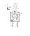
まず、図1には、車両用ストップランプスイッチの全体構成を示しており、密閉ケース1を主体としている。この密閉ケース1は、ケース主体部1aと、ケース底板1bとから成っており、そのうちのケース主体部1aは、上面部が閉塞され、底部が開放した、全体として方形の箱から成っている。
Hereinafter, the present invention is applied to a stop lamp switch for a vehicle, and a first example (first embodiment) thereof will be described with reference to FIGS.
First, FIG. 1 shows an overall configuration of a vehicle stop lamp switch, which mainly includes a sealed
ケース主体部1aの上面部の中央一帯には凹部2を形成しており、この凹部2の底部からケース主体部1aの内部へ、ヨーク3,4を貫通させた状態で設けている。このヨーク3,4は、ともに鉄等の磁性材から成るもので、要するに磁性を有しており、それらを例えばケース主体部1aの成形時にインサートして設けることにより、該ケース主体部1aと一体化している。その一体化した形態は、ヨーク3,4の各中間部がケース主体部1aの上壁部に密着されて保持され、それによって、ケース主体部1aの上壁部で隔てられた上下2つの空間に浸透性を有しないようになっているものであり、そこからヨーク3,4の各上部が、ケース主体部1aの上壁部より上方の空間であるケース主体部1a外(凹部2内)に突出し、各下部が、ケース主体部1aの上壁部より下方の空間であるケース主体部1a内に突出するものである。
A
又、ケース主体部1a内には、ヨーク3,4の間に位置して磁石(永久磁石)5を設けている。この磁石5も、例えばケース主体部1aの成形時にインサートして設けることにより、該ケース主体部1aと一体化しており、その一体化した形態は、磁石5の上部がケース主体部1aの上部壁中に位置して、両側面がヨーク3,4に接触し、下面がケース主体部1a内に露出するものである。
A magnet (permanent magnet) 5 is provided between the
ヨーク3,4は図で左右に並んでおり、その直下位置には可動コンタクト6を配置している。この可動コンタクト6は、この場合、非磁性材であるりん青銅等の導電性ばね材から成るコンタクト主板6aと、これの上面に固着した鉄等の磁性材から成る磁性板6bとから成っており、その磁性板6bによって磁性を有している。
The
コンタクト主板6aは例えば接続端子7と一体に形成しており、接続端子7は接続端子8と共にケース底板1bに貫通させた状態で設けている。詳細には、接続端子7,8も、ケース底板1bの成形時にインサートして設けることにより、該ケース主体部1aと一体化しており、その一体化した形態は、接続端子7,8の各上部がケース底板1bに密着されて保持され、それによって、ケース底板1bで隔てられた上下2つの空間に浸透性を有しないようになっているものであり、そこから接続端子7,8の各下部がケース底板1b下に突出するものである。
The contact
なお、上記ケース底板1bに接続端子7,8を一体化するについては、ケース底板1bに孔をあけ、その孔に接続端子7,8を通して、それらと孔との間の隙間を封止剤により埋めて密閉する構造を採用しても良い。又、その構造は、前記ケース主体部1aにヨーク3,4を一体化する部分にも採用することが可能で、すなわち、ケース主体部1aに孔をあけ、その孔にヨーク3,4を通して、それらと孔との間の隙間を封止剤により埋めて密閉する構造を採用しても良い。
For connecting the
可動コンタクト6のコンタクト主板6aは、上記接続端子7の上部から図で左側の斜め上方へ延びて、更にそこから、常態では、図3で左側の斜め下方へと延びている。そして、ケース底板1bは、ケース主体部1aの底部に結合されて、該底部の開放部を密に閉塞しており、その状態で、可動コンタクト6は、上記接続端子7の上部から上方へ延びたコンタクト主板6aの頂部において、磁性板6bの右側端部が右側のヨーク4の下端部に接触している。
The contact
従って、可動コンタクト6の図3で左側の斜め下方へと延びた部分は、本来、左側のヨーク3の下方に離間して位置するが、前記磁石5の磁力がヨーク3,4を通じて可動コンタクト6(磁性板6b)にのみ及ぶ図1及び図2に示す状況では、ヨーク3,4を介して磁石5に吸引され、ほゞ水平状に弾性変形されている。
Accordingly, the portion of the
しかして、コンタクト主板6aの先端部(左端部)には、接点9を上面側に設けている。これに対して、接点9の上方には、固定コンタクト10の接点11を接点9に対向させて配置しており、可動コンタクト6が上述のように磁石5に吸引されてほゞ水平状に弾性変形された状態では、該可動コンタクト6の接点9が固定コンタクト10の接点11に接触している。固定コンタクト10は前記接続端子8と一体に形成している。
Therefore, the
ケース底板1bは、既述のようにケース主体部1aの底部に結合しており、それによって、前記密閉ケース1を構成すると共に、その密閉ケース1の内部に、固定コンタクト10と、可動コンタクト6、磁石5、及びヨーク3,4の下部を収納する構造となしている。
なお、ケース底板1bから下方へ突出した接続端子7,8は、ケース底板1bと一体に形成した筒部1cに囲繞されていて、その筒部1c内に挿入される図示しないコネクタを介して図示しない導電線が接続されるようになっている。
As described above, the
The
そして、密閉ケース1(ケース主体部1a)の外部にはカバー12を装着しており、このカバー12は上部の中央部に筒状部12aを有していて、この筒状部12aにロッド状の移動子13を挿通している。移動子13は、筒状部12aより下方(カバー12と密閉ケース1との間)に位置する下部につば部13aを有しており、このつば部13aから下方に短円筒状のホルダ部13bを形成していて、更に、そのホルダ部13bより内方の中心部下端から上方へは穴14を形成している。
A
上記移動子13の穴14には、弾性体としてのコイルスプリング15を収納しており、又、ホルダ部13b内には磁気短絡体16を収納していて、この磁気短絡体16をコイルスプリング15で押し下げ、ホルダ部13bの下端内フランジ部13cで止めている。この結果、磁気短絡体16は移動子13にコイルスプリング15の伸縮方向(移動子13の移動方向)に移動可能に取付けられている。磁気短絡体16は、鉄等の磁性材から成るもので、この場合、移動子13のホルダ部13bと共に前記密閉ケース1の凹部2に進入することが可能な大きさの盤状を成している。
A
更に、移動子13のつば部13aの下面部には、ばね座凹環部17を形成しており、このばね座凹環部17と前記密閉ケース1(ケース主体部1a)の上面部との間には、コイルスプリング18を介在させている。このコイルスプリング18は、常時は移動子13を押し上げて、磁気短絡体16を前記密閉ケース1の凹部2のほゞ最上部(ヨーク3,4の上端部より上方に離間する位置)に位置させる付勢力を呈する付勢手段として機能するようになっている。
なお、移動子13の上部は、前記カバー12の筒状部12aより上方に突出して、図示しない車両のブレーキペダルに対応している。
Further, a spring seat
The upper portion of the
次に、上記構成のものの作用を述べる。
車両のブレーキペダルを踏み込み操作する前、車両用ストップランプスイッチは図1に示した状態にあり、すなわち、前述のように、移動子13がコイルスプリング18により押し上げられて、磁気短絡体16をヨーク3,4の上端部より上方に離間する位置に保持している。
Next, the operation of the above configuration will be described.
Before depressing the brake pedal of the vehicle, the vehicle stop lamp switch is in the state shown in FIG. 1, that is, as described above, the
この結果、可動コンタクト6は、磁石5の磁力がヨーク3,4を通じて可動コンタクト6にのみ及ぶことにより、ヨーク3,4を介して磁石5に吸引され、ほゞ水平状に弾性変形されて、接点9を固定コンタクト10の接点11に接触させている。従って、このとき、可動コンタクト6は、接続端子7,8間を、可動コンタクト6及び固定コンタクト10を介する電路で導通させている。
As a result, when the magnetic force of the
この状態から、車両のブレーキペダルが踏み込み操作されると、それに応じて移動子13がコイルスプリング18を圧縮して磁気短絡体16を伴い図3に矢印Aで示すように移動する。よって、磁気短絡体16はヨーク3,4の上端部に接触する。なお、このヨーク3,4の上端部に対する磁気短絡体16の接触は、コイルスプリング15を圧縮しつつ行われることにより、弾性的に行われる。
When the brake pedal of the vehicle is depressed from this state, the
そして、そのようにヨーク3,4の上端部に磁気短絡体16が接触すれば、磁石5の磁力はヨーク3,4を介して前記可動コンタクト6に及ぶのみならず、磁気短絡体16にも及ぶようになるから、その分、可動コンタクト6に及ぶ磁力が変化し(この場合、弱まり)、可動コンタクト6に対する吸引力が変化する(この場合、弱まる)。よって、可動コンタクト6に対する磁石5の吸引力よりも、可動コンタクト6の前記弾性変形状態からの復元力が勝るようになって、可動コンタクト6は復元し、図3に示すように、接点9を固定コンタクト10の接点11から離間させるので、前記接続端子7,8間の電路が遮断される。かくして、車両用ストップランプスイッチが車両のブレーキペダルが踏み込み操作に応動するものであり、もって、図示しない車両のストップランプを点灯させるに至る。
If the magnetic shorting
なお、車両のブレーキペダルの踏み込み操作が解除されれば、すべては原状態に復帰し、可動コンタクト6が磁石5に吸引されて接点9を固定コンタクト10の接点11に接触させることにより、車両のストップランプが消灯されるに至る。
If the operation of depressing the brake pedal of the vehicle is released, everything returns to the original state, and the
このように本構成のものでは、密閉ケース1内の可動コンタクト6にヨーク3,4を介して及ぶ磁石5の磁気吸引力が、密閉ケース1外の移動子13の移動による磁気短絡体16の移動で変化することにより、密閉ケース1内に進入することなく、可動コンタクト6を固定コンタクト10に対して動かすことができる。よって、密閉ケース1内には近辺に存在する潤滑油や無機物、有機物の異物が浸入することもなく、該密閉ケース1に収納した可動コンタクト6及び固定コンタクト10の接離を行わしめることができるものであり、それによって、従来あった、浸入物によるコンタクト6,10間の導通不良の問題を惹起するおそれをなくすことができる。
As described above, in this configuration, the magnetic attraction force of the
又、上記密閉ケース1内の可動コンタクト6にヨーク3,4を介して及ぶ磁石5の磁気吸引力の、磁気短絡体16の移動による変化は、磁石5自体を動かす場合に比べて急峻にできるものであり、それによって、可動コンタクト6及び固定コンタクト10の接離がより速やかにでき、スイッチ性能を向上させることができる。
Further, the change of the magnetic attractive force of the
以上に対して、図4ないし図7は本発明の第2及び第3実施例(第2及び第3の実施形態)を示すもので、それぞれ、上記第1実施例と同一もしくは同様の部分には同一の符号を付して説明を省略し、異なる部分についてのみ述べる。
[第2実施例]
図4ないし図6に示す第2実施例においては、まず、密閉ケース21を、第1実施例の密閉ケース1に代えて、ほゞドーム状のケース主体部21aと、ケース底板21bとにより構成している。
4 to 7 show the second and third examples (second and third embodiments) of the present invention, and are respectively the same as or similar to the first example. Are denoted by the same reference numerals, description thereof is omitted, and only different portions are described.
[Second Embodiment]
In the second embodiment shown in FIGS. 4 to 6, first, the sealed
ケース主体部21aの上部には、ヨーク22,23を、第1実施例のケース主体部1aに対するヨーク3,4と同様に、但し、ヨーク3,4よりも大きくケース主体部1aの上方へ突出するように設けている。ヨーク22,23は、第1実施例のヨーク3,4に代わるもので、ともに鉄等の磁性材から成り、磁性を有している。
At the upper part of the case
ケース主体部21a内には、磁石5をヨーク22,23の間に接触位置させて設けており、ヨーク22,23の直下位置に可動コンタクト24を配置している。この可動コンタクト24は、第1実施例の可動コンタクト6に代わるもので、非磁性材であるりん青銅等の導電性ばね材から成るコンタクト主板24aと、これの上面に固着した鉄等の磁性材から成る磁性板24bとから成って、その磁性板24bにより磁性を有する点は、第1実施例の可動コンタクト6と同様であるが、そのコンタクト主板24aの先端部には、接点9を下面側に設けている。
In the case
コンタクト主板24aは前記接続端子7に接合しており、接続端子7は接続端子8と共にケース底板21bに密着状態に貫通させて設けている。更に、コンタクト主板24aは、第1実施例の可動コンタクト6と同様に、接続端子7との接合部分から図4及び図5で左側の斜め上方へ延びて、更にそこから、常態では、図4及び図5で左側の斜め下方へと延びている。
The contact
そして、ケース底板21bは、ケース主体部21aの底部に結合されて、該底部の開放部を密に閉塞しており、その状態で、可動コンタクト24は、第1実施例の可動コンタクト6と同様に、上記接続端子7との接合部分から斜め上方へ延びたコンタクト主板24aの頂部において、磁性板24bの右側端部が右側のヨーク23の下端部に接触している。又、可動コンタクト24の図4及び図5で左側の斜め下方へと延びた部分は、左側のヨーク22の下方に離間して位置している。
The case
前記接点9の下方には、固定コンタクト25の接点11を接点9に対向させて接触するように配置しており、固定コンタクト25は前記接続端子8と一体に形成している。
ケース底板21bは、上述のようにケース主体部21aの底部に結合しており、それによって、前記密閉ケース21を構成すると共に、その密閉ケース21の内部に、固定コンタクト25と、可動コンタクト24、磁石5、及びヨーク22,23の下部を収納する構造となしている。
Below the
As described above, the case
ケース底板21bには、下方に、接続端子7,8を囲繞する筒部21cを形成すると共に、上方にケース主体部21aを囲繞する筒部21dを形成しており、この上方の筒部21dの外部にカバー12を装着している。
カバー12の筒状部12aには、第1実施例の移動子13に代えて、つば部及びホルダ部のないロッド状の移動子26を挿通しており、これに対して、前記ヨーク22,23の上部に折曲形成したストッパ部22a,23aの間には、磁気短絡体27を配置している。この磁気短絡体27は、第1実施例の磁気短絡体16に代わるもので、鉄等の磁性材から成っており、両端部が上記ストッパ部22a,23aの下側に位置している。
The case
Instead of the
磁気短絡体27と前記密閉ケース21(ケース主体部21a)の上面部との間には、コイルスプリング28を介在させており、このコイルスプリング28は、常時は磁気短絡体27を押し上げて上記ストッパ部22a,23aに接触させ、ひいてはヨーク22,23に接触させる付勢力を呈する付勢手段として機能するようになっている。
A
磁気短絡体27の中央部には孔29を形成しており、前記密閉ケース21(ケース主体部21a)の上面部と、前記移動子26の下端から上方へ形成した穴30の奥端部との間には、コイルスプリング31を上記磁気短絡体27の孔29を通して介在させている。このコイルスプリング31は、常時は移動子26を押し上げて、磁気短絡体27から離間させる付勢力を呈する付勢手段として機能するようになっている。
なお、移動子26の上部は、第1実施例の移動子13と同様に、カバー12の筒状部12aより上方に突出して、図示しない車両のブレーキペダルに対応している。
A
The upper portion of the
次に、この第2実施例の作用を述べる。
車両のブレーキペダルを踏み込み操作する前、車両用ストップランプスイッチは図4に示した状態にあり、すなわち、前述のように、磁気短絡体27がコイルスプリング28により押し上げられてヨーク22,23に接触され、移動子13がコイルスプリング31により押し上げられて磁気短絡体27から離間している。
Next, the operation of the second embodiment will be described.
Before depressing the brake pedal of the vehicle, the vehicle stop lamp switch is in the state shown in FIG. 4, that is, as described above, the magnetic short-
この結果、磁石5の磁力はヨーク3,4を通じて磁気短絡体27により短絡され、可動コンタクト24(磁性板24b)には及ばないから、可動コンタクト24は常態のままで、図4及び図5で左側の斜め下方へと延びた部分が左側のヨーク22の下方に離間し、接点9を固定コンタクト10の接点11に接触させている。従って、このとき、可動コンタクト24は、接続端子7,8間を、可動コンタクト24及び固定コンタクト25を介する電路で導通させている。
As a result, the magnetic force of the
この状態から、車両のブレーキペダルが踏み込み操作されると、それに応じて移動子26がコイルスプリング31を圧縮して図6に矢印Aで示すように移動する。このように移動した移動子26は下端部で磁気短絡体27を押し、該磁気短絡体27をヨーク22,23から離間させる。なお、この移動子26による磁気短絡体27の押圧移動は、コイルスプリング28,31を圧縮しつつ行われることにより、弾性的に行われる。
From this state, when the brake pedal of the vehicle is depressed, the
そして、そのように磁気短絡体27がヨーク22,23から離間されれば、磁石5の磁力は、ヨーク3,4を通じての前記磁気短絡体27による短絡から解除されて、可動コンタクト6(磁性板24b)に及ぶようになる。その結果、可動コンタクト6がヨーク3,4を介し磁石5に吸引されてほゞ水平状に弾性変形され、接点9を固定コンタクト10の接点11から離間させる。よって、前記接続端子7,8間の電路が遮断されるものであり、かくして、車両用ストップランプスイッチが車両のブレーキペダルが踏み込み操作に応動し、図示しない車両のストップランプを点灯させるに至る。
If the magnetic short-
なお、車両のブレーキペダルの踏み込み操作が解除されれば、すべては原状態に復帰し、可動コンタクト24が磁石5による吸引から解放されて接点9を固定コンタクト25の接点11に接触させることにより、車両のストップランプが消灯されるに至る。
If the operation of depressing the brake pedal of the vehicle is released, everything returns to the original state, and the
すなわち、この第2実施例は、車両のブレーキペダルの踏み込み操作前と踏み込み操作時における、ヨーク22,23に対する磁気短絡体27の接触、離間の動作を、第1実施例とは逆にしたもので、それ以外は第1実施例と同様であり、従って、第1実施例と同様の異物の侵入防止効果並びにスイッチ性能向上の効果を得ることができる。
That is, in the second embodiment, the operation of contacting and separating the magnetic short-
[第3実施例]
図7に示す第3実施例においては、先の第1実施例におけるケース主体部1aのヨーク3,4にそれぞれ外側で隣接する部分41,42を上下に延出させ、内側で隣接する部分43を上方に延出させている。
[Third embodiment]
In the third embodiment shown in FIG. 7, the
ここで、ヨーク3,4と磁気短絡体16が金属製であるのに対し、ケース主体部1aは、ヨーク3,4をインサートして成形した樹脂、特には合成樹脂から成るものであり、ケース主体部1aはそのヨーク3,4を密着して保持している関係上、ヨーク3,4に樹脂製の部材として該ケース主体部1aの延出部41〜43が密着して一体化されている。又、樹脂は防音部材であり、従って、ヨーク3,4には、樹脂製の防音部材として延出部41〜43が密着して一体化されている。
Here, the
そして又、それら延出部41〜43のそれぞれ上方に延びた部分は、ヨーク3,4よりも磁気短絡体16側である上方に少し突出しており、従って、防音部材がヨーク3,4よりも磁気短絡体16側に突出している。
Further, the portions extending upward of the extending
このように構成したものでは、ヨーク3,4に磁気短絡体16が接触しようとするときの衝突によるヨーク3,4の振動を延出部41〜43(防音部材)で抑制し、それによって音の発生を鈍く小さくすることができる。
With this configuration, the vibrations of the
特に、延出部41〜43のそれぞれ上方に延びた部分が、ヨーク3,4よりも磁気短絡体16側に突出していることにより、ヨーク3,4に接触しようとするときの磁気短絡体16は、延出部41〜43のそれぞれヨーク3,4よりも磁気短絡体16側に突出している部分に当たり、ヨーク3,4への当たりが避けられるから、ヨーク3,4に磁気短絡体16が接触しようとするときの衝突による音の発生をより小さくすることができる。
In particular, the portions that extend upward from the extending
このほか、本発明は上記し且つ図面に示した実施例にのみ限定されるものではなく、特に、固定コンタクトと可動コンタクトについては、可動コンタクトが車両のブレーキペダルの踏み込み操作前は固定コンタクトから離間し、車両のブレーキペダルの踏み込み操作に応じて可動コンタクトが固定コンタクトに接触するように変えても良い。 In addition, the present invention is not limited to the embodiment described above and shown in the drawings. In particular, with respect to the fixed contact and the movable contact, the movable contact is separated from the fixed contact before the brake pedal is depressed. However, the movable contact may be changed so as to come into contact with the fixed contact according to the depression operation of the brake pedal of the vehicle.
又、可動コンタクトは、導電材(非磁性材)から成るコンタクト主板及び磁性材から成る磁性板の二部材から成るものでなく、導電性を有する磁性材の一部材で形成されていても良く、特にそのようにした場合には、使用部品点数を少なく済ませ得る効果がある。
更に、本発明は、車両用のストップランプスイッチ以外の、それと同様の事情を有するスイッチ装置一般に適用できるものであり、そのほか、要旨を逸脱しない範囲内で適宜変更して実施し得る。
Further, the movable contact is not composed of two members of a contact main plate made of a conductive material (non-magnetic material) and a magnetic plate made of a magnetic material, and may be formed of one member of a magnetic material having conductivity, In particular, in such a case, there is an effect that the number of used parts can be reduced.
Furthermore, the present invention can be applied to switch devices having the same circumstances as those other than the stop lamp switch for a vehicle, and can be appropriately modified and implemented without departing from the scope of the invention.
図面中、1は密閉ケース、3,4はヨーク、5は磁石、6は可動コンタクト、10は固定コンタクト、13は移動子、16は磁気短絡体、21は密閉ケース、22,23はヨーク、24は可動コンタクト、25は固定コンタクト、26は移動子、27は磁気短絡体、41〜43はケース主体部の延出部(樹脂製の防音部材)を示す。
In the drawings, 1 is a sealed case, 3 and 4 are yokes, 5 is a magnet, 6 is a movable contact, 10 is a fixed contact, 13 is a moving element, 16 is a magnetic short circuit, 21 is a sealed case, 22 and 23 are yokes,
Claims (4)
この固定コンタクトと対応する、磁性を有する可動コンタクトと、
これら固定コンタクト及び可動コンタクトを収納した密閉ケースと、
前記可動コンタクトと対応する、磁性を有するヨークと、
このヨークに磁力を及ぼして該ヨークを介し前記可動コンタクトを吸引する磁石と、
前記密閉ケースの外部に位置して移動操作される移動子と、
この移動子により移動される磁気短絡体とを具備し、
その磁気短絡体が移動により前記ヨークとの距離を変化させることによって、該ヨークを介しての前記磁石による可動コンタクトの吸引力を変化させ、該可動コンタクトを固定コンタクトに対して動かすようにしたことを特徴とするスイッチ装置。 A fixed contact;
A magnetic movable contact corresponding to the fixed contact;
A sealed case containing these fixed and movable contacts;
A magnetic yoke corresponding to the movable contact;
A magnet that exerts a magnetic force on the yoke to attract the movable contact through the yoke;
A mover that is moved and operated outside the sealed case;
Comprising a magnetic short-circuit that is moved by the mover;
The magnetic short-circuiting body changes the distance to the yoke by movement, thereby changing the attractive force of the movable contact by the magnet through the yoke and moving the movable contact with respect to the fixed contact. A switch device characterized by.
Priority Applications (2)
| Application Number | Priority Date | Filing Date | Title |
|---|---|---|---|
| JP2007259987A JP4906112B2 (en) | 2007-04-23 | 2007-10-03 | Switch device |
| US12/081,867 US7750771B2 (en) | 2007-04-23 | 2008-04-22 | Switching device |
Applications Claiming Priority (3)
| Application Number | Priority Date | Filing Date | Title |
|---|---|---|---|
| JP2007113002 | 2007-04-23 | ||
| JP2007113002 | 2007-04-23 | ||
| JP2007259987A JP4906112B2 (en) | 2007-04-23 | 2007-10-03 | Switch device |
Publications (2)
| Publication Number | Publication Date |
|---|---|
| JP2008293941A JP2008293941A (en) | 2008-12-04 |
| JP4906112B2 true JP4906112B2 (en) | 2012-03-28 |
Family
ID=40168441
Family Applications (1)
| Application Number | Title | Priority Date | Filing Date |
|---|---|---|---|
| JP2007259987A Expired - Fee Related JP4906112B2 (en) | 2007-04-23 | 2007-10-03 | Switch device |
Country Status (2)
| Country | Link |
|---|---|
| US (1) | US7750771B2 (en) |
| JP (1) | JP4906112B2 (en) |
Families Citing this family (9)
| Publication number | Priority date | Publication date | Assignee | Title |
|---|---|---|---|---|
| FR2903807B1 (en) * | 2006-07-12 | 2009-10-09 | Schneider Electric Ind Sas | SWITCHING DEVICE INCLUDING A MOBILE FERROMAGNETIC PART |
| JP4906113B2 (en) * | 2007-10-03 | 2012-03-28 | 株式会社東海理化電機製作所 | Switch device |
| JP4989504B2 (en) * | 2008-02-12 | 2012-08-01 | 株式会社東海理化電機製作所 | Switch device |
| CH700989A1 (en) * | 2009-04-07 | 2010-10-15 | Polycontact Ag | Electrical switching element. |
| CN201774463U (en) * | 2010-06-14 | 2011-03-23 | 鸿富锦精密工业(深圳)有限公司 | energy-saving adapter |
| CN102184790A (en) * | 2010-07-30 | 2011-09-14 | 鸿富锦精密工业(深圳)有限公司 | Switching device |
| CN202855634U (en) * | 2012-05-14 | 2013-04-03 | 通用设备和制造公司 | Magnetic switch driver |
| CN103714999A (en) * | 2012-09-29 | 2014-04-09 | 启东恒瑞防爆通讯电气有限公司 | Improved magnetic explosion-proof switch |
| CN103714995A (en) * | 2012-09-29 | 2014-04-09 | 启东恒瑞防爆通讯电气有限公司 | Improved explosion-proof switch |
Family Cites Families (17)
| Publication number | Priority date | Publication date | Assignee | Title |
|---|---|---|---|---|
| US2240847A (en) * | 1938-08-11 | 1941-05-06 | Milwaukee Gas Specialty Co | Magnetic switch |
| US2521723A (en) * | 1945-02-03 | 1950-09-12 | Hubbell Harvey | Magnetically controlled switch |
| US3024411A (en) * | 1957-02-27 | 1962-03-06 | Silec Liaisons Elec | Magnetic switching device |
| DE1290221B (en) * | 1963-08-02 | 1969-03-06 | Baermann Max | Magnetically operated switching device |
| US3284743A (en) * | 1965-05-10 | 1966-11-08 | Westinghouse Electric Corp | Magnetic switching device |
| JPS445799Y1 (en) * | 1965-12-22 | 1969-03-03 | ||
| US3539957A (en) * | 1968-08-09 | 1970-11-10 | Aerolite Electronics Corp | Magnetic switch |
| US3539741A (en) * | 1969-08-08 | 1970-11-10 | Mallory & Co Inc P R | Magnetically activated door switch |
| JPS5355777A (en) * | 1976-11-01 | 1978-05-20 | Makoto Katsurai | Orthogonal magnetic field discharge switch |
| US4150350A (en) * | 1976-12-16 | 1979-04-17 | Fong Lee W | Magnetic switch |
| JPS55108623A (en) * | 1979-02-14 | 1980-08-21 | Sharp Corp | Display cell and production thereof |
| JPS5921122B2 (en) * | 1979-07-06 | 1984-05-17 | コビシ電機株式会社 | magnetic proximity switch |
| US4596971A (en) * | 1984-07-26 | 1986-06-24 | Tdk Corporation | Magnetic circuit device |
| US4751485A (en) * | 1987-08-12 | 1988-06-14 | Clairol Incorporated | Waterproof switch assembly for electrical appliances |
| JP3996758B2 (en) * | 2001-03-13 | 2007-10-24 | 富士通コンポーネント株式会社 | Operating condition constrained switch, external magnetic field generation unit, operating condition constrained switch device, and electronic device |
| JP2005235632A (en) | 2004-02-20 | 2005-09-02 | Tokai Rika Co Ltd | Stop lamp switch |
| US7167675B2 (en) * | 2004-10-15 | 2007-01-23 | Leapfrog Enterprises, Inc. | Magnetic switch and apparatus including magnetic switch |
-
2007
- 2007-10-03 JP JP2007259987A patent/JP4906112B2/en not_active Expired - Fee Related
-
2008
- 2008-04-22 US US12/081,867 patent/US7750771B2/en not_active Expired - Fee Related
Also Published As
| Publication number | Publication date |
|---|---|
| JP2008293941A (en) | 2008-12-04 |
| US7750771B2 (en) | 2010-07-06 |
| US20090072936A1 (en) | 2009-03-19 |
Similar Documents
| Publication | Publication Date | Title |
|---|---|---|
| JP4906112B2 (en) | Switch device | |
| JP4906113B2 (en) | Switch device | |
| CN102024625B (en) | Electromagnetic relay | |
| JP4989504B2 (en) | Switch device | |
| WO2017183305A1 (en) | Contact switching device and electromagnetic relay using same | |
| KR20200137265A (en) | Direct current relay and method of fabrication thereof | |
| KR20200137266A (en) | Direct current relay | |
| JP2008084584A (en) | Stop lamp switch for vehicle | |
| CN112912985A (en) | contact device | |
| JP4453676B2 (en) | Electromagnetic relay | |
| JP4702380B2 (en) | Contact device | |
| JP2011034771A (en) | Switch device | |
| KR101006320B1 (en) | Relay structure for high voltage | |
| JP5107851B2 (en) | Switch device | |
| WO2020148995A1 (en) | Relay | |
| JP2009087906A (en) | Switching device | |
| JP2009087905A (en) | Switching device | |
| JP2007329023A (en) | Vehicle switch | |
| JP2008084583A (en) | Stop lamp switch for vehicle | |
| WO2020148994A1 (en) | Relay | |
| JP2005019139A (en) | Contact structure of switch | |
| JP7390791B2 (en) | relay | |
| CN201323143Y (en) | Switch | |
| CN115116795A (en) | Electromagnetic relay | |
| JP2021044213A (en) | Electromagnetic relay |
Legal Events
| Date | Code | Title | Description |
|---|---|---|---|
| A621 | Written request for application examination |
Free format text: JAPANESE INTERMEDIATE CODE: A621 Effective date: 20100611 |
|
| A977 | Report on retrieval |
Free format text: JAPANESE INTERMEDIATE CODE: A971007 Effective date: 20111207 |
|
| TRDD | Decision of grant or rejection written | ||
| A01 | Written decision to grant a patent or to grant a registration (utility model) |
Free format text: JAPANESE INTERMEDIATE CODE: A01 Effective date: 20111213 |
|
| A01 | Written decision to grant a patent or to grant a registration (utility model) |
Free format text: JAPANESE INTERMEDIATE CODE: A01 |
|
| A61 | First payment of annual fees (during grant procedure) |
Free format text: JAPANESE INTERMEDIATE CODE: A61 Effective date: 20120106 |
|
| FPAY | Renewal fee payment (event date is renewal date of database) |
Free format text: PAYMENT UNTIL: 20150120 Year of fee payment: 3 |
|
| R150 | Certificate of patent or registration of utility model |
Free format text: JAPANESE INTERMEDIATE CODE: R150 |
|
| LAPS | Cancellation because of no payment of annual fees |