JP4903988B2 - A heat dissipation system that convects by the thermal operation of a natural thermocarrier - Google Patents
A heat dissipation system that convects by the thermal operation of a natural thermocarrier Download PDFInfo
- Publication number
- JP4903988B2 JP4903988B2 JP2004100005A JP2004100005A JP4903988B2 JP 4903988 B2 JP4903988 B2 JP 4903988B2 JP 2004100005 A JP2004100005 A JP 2004100005A JP 2004100005 A JP2004100005 A JP 2004100005A JP 4903988 B2 JP4903988 B2 JP 4903988B2
- Authority
- JP
- Japan
- Prior art keywords
- heat
- fluid
- pipe
- active
- natural
- Prior art date
- Legal status (The legal status is an assumption and is not a legal conclusion. Google has not performed a legal analysis and makes no representation as to the accuracy of the status listed.)
- Expired - Fee Related
Links
Images


Classifications
-
- Y—GENERAL TAGGING OF NEW TECHNOLOGICAL DEVELOPMENTS; GENERAL TAGGING OF CROSS-SECTIONAL TECHNOLOGIES SPANNING OVER SEVERAL SECTIONS OF THE IPC; TECHNICAL SUBJECTS COVERED BY FORMER USPC CROSS-REFERENCE ART COLLECTIONS [XRACs] AND DIGESTS
- Y02—TECHNOLOGIES OR APPLICATIONS FOR MITIGATION OR ADAPTATION AGAINST CLIMATE CHANGE
- Y02E—REDUCTION OF GREENHOUSE GAS [GHG] EMISSIONS, RELATED TO ENERGY GENERATION, TRANSMISSION OR DISTRIBUTION
- Y02E10/00—Energy generation through renewable energy sources
- Y02E10/10—Geothermal energy
Description
本発明は、自然サーモキャリアの熱作動で対流する放熱システムに関するものである。即ち、自然サーモキャリアを使って、より低い温度の流体を加温し、流体の寒い時下がり、暑い時上がる特性を利用して、放熱を受ける温度差体に開放型又は封鎖型の機能を行なうのである。 The present invention relates to a heat dissipation system that convects by the thermal operation of a natural thermocarrier. That is, a natural thermocarrier is used to heat a fluid at a lower temperature, and the temperature difference body that receives heat radiation is used as an open type or a sealed type function by using the characteristic that the fluid is lowered when it is cold and rises when it is hot. It is.
従来、異なる空間の流体に加温又は放熱を行なう場合、通常、熱ポンプで交換を実施し、作動の補助として、流体ポンプを設けることが必要なので、そのシステムに動力源が必要であるし、その設置コストがより高いし、運転する時は、エネルギーを使うことが必要なので、その運転コストもより高いのである。 Conventionally, when heating or radiating heat to fluids in different spaces, it is usually necessary to replace with a heat pump and provide a fluid pump as an auxiliary to the operation, so the system needs a power source, The installation cost is higher, and when operating it is necessary to use energy, so the operating cost is also higher.
本発明の目的は、自然サーモキャリアの熱作動で対流する放熱システムに関するものである。それは、熱貯蔵がより安定する地層、地表、池、湖、川、砂漠、氷山又は海洋などの固体又は液体のサーモキャリアに能動熱作動器を設けて、能動熱作動器の両端にそれぞれ流体の配管を設けることで、それぞれ温度差体及び放熱を受ける温度差体に流れる。それによって、熱作動で対流する装置のようなものを構成する。この熱作動で対流する装置を通して、温度差体より進入口配管から能動熱作動器108に入るより低い温度の流体が加温されるので、流体の寒い時下がり、暑い時上がる特性を利用して、対流機能を生じさせる。又、出口配管から放熱を受ける温度差体に流れることで開放型の放熱システムが構成され、又は、配管を通して能動放熱器201に流してから、再び配管を通して能動熱作動器108に流れて戻ることで、封鎖型の放熱システムが構成されるのである。
The objective of this invention is related with the thermal radiation system which convects by the thermal action of a natural thermocarrier. It has active thermal actuators on solid or liquid thermocarriers such as strata, surface, pond, lake, river, desert, iceberg or ocean where heat storage is more stable, By providing piping, it flows through the temperature difference body and the temperature difference body that receives heat dissipation, respectively. Thereby, it constitutes something like a convection device with thermal actuation. Through this thermal convection device, the lower temperature fluid that enters the active
本発明は、主に、より安定する地層、地表、池、湖、川、砂漠、氷山又は海洋などの固体又は液体のサーモキャリアに能動熱作動器及び流体の配管を設けることで、熱作動の対流装置のようなものを構成する。この熱作動で対流する装置を通して、能動熱作動器に入るより低い温度の流体が加温されるので、流体の寒い時下がり、暑い時上がる特性を利用して、放熱を受ける温度差体に流れる。 The present invention mainly provides active thermal actuators and fluid piping on solid or liquid thermocarriers such as more stable formations, surface, ponds, lakes, rivers, deserts, icebergs or oceans. It constitutes something like a convection device. Through this thermally actuated convection device, the lower temperature fluid entering the active thermal actuator is warmed up, so that it flows to the temperature difference body that receives heat dissipation by utilizing the characteristics of the fluid that falls when it is cold and rises when it is hot .
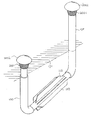
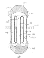
図1は、本発明の実施例による自然サーモキャリアの対流放熱システムの開放型を呈する放熱システムの立体構造の斜視図である。図2は、図1の断面図である。図1及び図2で示される熱作動で対流する装置100の中の配管の進入口111をより低い場所に選んで設けることで、より低い温度の熱交換流体104が下に流す配管の進入口111に入りやすくなるが、配管の排出口112をより高い場所に選んで設けることで、能動熱作動器108で加温される熱交換流体104を上の配管の排出口112に排出しやすくなる。それによって、開放型の放熱システムが構成されるのである。その構造の特徴は、下記のものを含む。
FIG. 1 is a perspective view of a three-dimensional structure of a heat dissipating system showing an open type of a natural thermocarrier convective heat dissipating system according to an embodiment of the present invention. FIG. 2 is a cross-sectional view of FIG. The piping inlet 111 of the
自然サーモキャリア101は、熱貯蔵がより安定する地層、地表、池、湖、川、砂漠、氷山又は海洋などの固体又は液体のサーモキャリアである。
温度差体102は、より低い温度の気体、固体又は液体に関するものであり、それを常態で熱交換流体104と接触させることで、相互に均等な熱伝導を行なえるものである。
The
The temperature difference body 102 relates to a lower temperature gas, solid, or liquid, and can contact the
放熱を受ける温度差体103は、気体、固体又は液体で構成される特定の機能空間又は構造であり、それによって、システムの運転中、直接又は間接で能動熱作動器で加温される熱交換流体で釈放されるエネルギーの気体、固体又は液体を受ける。それは、屋根、路面、温室、水池、加温又は凍結防止の構造体で構成されるものである。 The temperature difference body 103 that receives heat is a specific functional space or structure composed of gas, solid, or liquid, and thereby heat exchange that is heated directly or indirectly by an active heat actuator during operation of the system. Receives gas, solid or liquid of energy released by fluid. It consists of a roof, road surface, greenhouse, water pond, warming or freezing structure.
熱交換流体104は、熱貯蔵及び熱伝導の性質が良い気体又は液体で構成するものを含む。又、それを常態で温度差体102と接触させることで、相互に均等な熱伝導を行なえるものである。
The
熱作動で対流する装置100は、少なくとも1個のより低い熱交換流体が下に流れる流体の配管106に流れていくことを提供することで、自然サーモキャリアの中に設けられる少なくとも1個の能動熱作動器108の底部と繋がるもの、及び少なくとも1個の加温した後の熱交換流体104が上に流れる流体の配管107を提供することで、能動熱作動器108の上方流体の出口と繋がるもので構成されるものである。
The thermally actuated
流体の配管106及び流体の配管107は、丸形又はその他幾何形状を呈するパイプ形状の構造物又は建築の構造体で構成され、又は、自然サーモキャリアの中の通路で構成され、下に流れる流体の配管106とその接触する自然サーモキャリア101との間に良い断熱構造109を備えるべきであり、又は、直接良い断熱材料で配管を構成する。その中で、少なくとも1個の下に流れる流体の配管106は、より低い温度の熱交換流体104が下に流れる流体の配管106の進入口111を経由してから、熱作動で対流する装置100の能動熱作動器108のより低い部分に入ることを提供する。又、少なくとも1個の上に流れる流体の配管107が、熱作動で対流する装置100の能動熱作動器108の上端から放熱を受ける温度差体103に流すことで、熱交換流体104が上に流れる流体の配管の排出口112を経由して、放熱を受ける温度差体103に排出されるものである。
The
能動熱作動器108は、熱作動で対流する装置100のより低い所に設けられ、配管と同一のサイズで一体として伸びて作ることができる。又は、流体の配管106及び流体の配管107と異なるサイズの構造で作ることもできる。その材料は、流体の配管106及び流体の配管107と同一の材料を使うか、その他良い熱伝導特性がある異なる材料で構成することができる。又、自然サーモキャリア101と良い熱伝導状態の構造形態を維持する。又は、直接自然サーモキャリア101の内部に流体を流通させる空間を利用して、直接能動熱作動器の機能を構成することで、前述の良い熱伝導特性の材料で作られる能動熱作動器108の代わりとして使われる。能動熱作動器のケースは、更に必要によって熱伝導フィンを増設することもできる。
The active
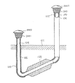
図3は、図1の自然サーモキャリアの対流放熱システムの更に封鎖流路を呈する封鎖型の放熱システムの立体構造の斜視図である。図4は、図3の断面図である。図3及び図4の熱作動で対流する装置100の中の能動熱作動器108に配置される流体の配管107の排出口112と流体の配管106の進入口111との間には、そのトップ端に能動放熱器201、流体の配管221及び流体の配管222を設けることで、封鎖配管構造を構成することができる。流体の配管107の排出口112を上がる流体の配管221と接続して、能動放熱器201のより高い位置に流すことで、能動熱作動器108からの加温された熱交換流体104を能動放熱器201に導入してから、能動放熱器201の周りの放熱を受ける温度差体103にエネルギーを放熱するもの、及び能動放熱器201のより低い位置に配置される流体の配管222が能動熱作動器108の配管の進入口111に流れることで、能動放熱器201からの熱交換流体104を能動熱作動器108に導入するもので、封鎖型の熱作動及び放熱の循環システムが構成されるのである。図3及び図4で示される封鎖型の熱作動及び放熱の循環システムは、図1及び図2で記載された自然サーモキャリア101、放熱を受ける温度差体103、熱交換流体104、熱作動で対流する装置100、流体の配管106及び流体の配管107を備えて、より低い温度の熱交換流体104を流すことを提供する他、又、流体の配管106の進入口111を経由して、能動熱作動器108の底部に入る。又、能動熱作動器108で加熱する熱交換流体104を能動熱作動器108の上部の上に流れる流体の配管107の排出口112より排出する。上述の構成ユニット他、その特徴は、下記のものを含むのである。
FIG. 3 is a perspective view of a three-dimensional structure of a sealed-type heat radiation system that further shows a sealed flow path of the convective heat radiation system of the natural thermocarrier of FIG. 4 is a cross-sectional view of FIG. 3 and FIG. 4, between the
流体の配管221及び流体の配管222は、1セット又は1セット以上の断熱構造109で、又は、良い断熱材質がある丸形又はその他幾何形状を呈するパイプ形状の構造物又は建築の構造体で構成される流体の配管221であり、その下端は流体の配管107の上に流れる配管の排出口112と繋がって、その上端は能動放熱器201の上端の進入口211と繋がることで、下から上に比較的高い温度の熱交換流体104を流すもので、及び少なくとも1セット又は1セット以上の断熱構造109、又は、良い断熱材質がある材料で構成される流体の配管222を通して、放熱して温度を下げた熱交換流体104を下に流させて、その下端が流体の配管106の進入口111に繋がって、その上端が能動放熱器201の下端の出口212に繋がることで、∩形状の放熱対流装置200を構成してから、能動熱作動器108、流体の配管106及び流体の配管107の熱作動で対流する装置100と共同で封鎖の放熱循環システムである。
The
能動放熱器201は、1セット又は1セット以上の従来の良い放熱材料及び一体又はマルチタイプの構造形態で構成され、更に、必要によって熱伝導フィン202を設けることで、又は、直接放熱機能がある流体の配管で構成される能動放熱器のである。
The
放熱を受ける温度差体103は、気体、固体又は液体で構成される特定の機能空間又は構造であり、それによって、システムの運転中、直接又は間接で能動熱作動器で加温される熱交換流体で釈放されるエネルギーの気体、固体又は液体を受けるものである。それは、屋根、路面、温室、水池、加温又は凍結防止の構造体で構成されるものである。 The temperature difference body 103 that receives heat is a specific functional space or structure composed of gas, solid, or liquid, and thereby heat exchange that is heated directly or indirectly by an active heat actuator during operation of the system. It receives gas, solid or liquid of energy released by fluid. It consists of a roof, road surface, greenhouse, water pond, warming or freezing structure.
図5は、本発明の能動熱作動器の内部に熱伝導フィン又は逆流防止め板が増設される開放型放熱システム構造例の斜視図である。図6は、図5の断面図である。図5及び図6の主要な特徴は、前述の図1及び図2で記載された自然サーモキャリアの熱作動で対流する放熱システムが開放式の立体構造を呈する。その中で、熱作動で対流する装置100の底部の能動熱作動器108の外部に、必要によって自然サーモキャリアとの熱伝導効果を増進できる熱伝導フィン1001を増設することで、自然サーモキャリアとの熱伝導効果を増進する。又、能動熱作動器108の内部に更に上に傾いて交差する熱伝導及び逆流を防止する止め板1002を設けることで、熱伝導効果を増加し、加温された後の熱交換流体104が逆方向に流れて戻ることを防止することができるのである。
FIG. 5 is a perspective view of an example of an open type heat dissipation system structure in which heat conducting fins or backflow prevention plates are added inside the active heat actuator of the present invention. 6 is a cross-sectional view of FIG. The main feature of FIGS. 5 and 6 is that the heat dissipation system convectioned by the thermal operation of the natural thermocarrier described in FIGS. 1 and 2 has an open three-dimensional structure. Among them, by adding
図7は、本発明の能動熱作動器の内部に熱伝導フィン又は逆流防止め板が増設される封鎖型放熱システム体構造例の斜視図である。図8は、図7の断面図である。図7及び図8の主要な特徴は、前述の図3及び図4で記載された自然サーモキャリアの熱作動で対流する放熱システムが封鎖型の立体構造を呈する。その中で、熱作動で対流する装置100の底部の能動熱作動器108及び相対的に高い場所に設けられる∩形状の放熱対流装置200の能動放熱器201は、必要によって自然サーモキャリアとの熱伝導効果を増進できる熱伝導フィン1001を増設することで、自然サーモキャリアとの熱伝導効果を増進する。又、能動熱作動器108及び能動放熱器201の内部に更に上に傾いて交差する熱伝導及び逆流を防止する止め板を設けることで、熱伝導効果を増加し、加温された後の熱交換流体104が逆方向に流れて戻ることを防止することができるのである。
FIG. 7 is a perspective view of an example of a structure of a sealed-type heat dissipation system body in which heat conductive fins or backflow prevention plates are added inside the active heat actuator of the present invention. FIG. 8 is a cross-sectional view of FIG. The main feature of FIGS. 7 and 8 is that the heat dissipating system that convects by the thermal operation of the natural thermocarrier described in FIGS. 3 and 4 has a sealed three-dimensional structure. Among them, the active
この自然サーモキャリアの熱作動で対流する放熱システムについて、能動熱作動器108及び能動放熱器201は、必要によって直線パイプ形状、曲線パイプ形状、螺旋パイプ形状、ウェーブパイプ形状又はその他2次元(2D)又は3次元(3D)の曲がる形状が上に向かって傾いて昇るパイプ形状の流体の配管の構造形態で構成され、その外部に必要によって熱伝導フィン1001を増設して、その内部に必要によって熱伝導及び逆流を防止する止め板を設けることができる。
With respect to the heat dissipation system that convects by the thermal operation of this natural thermocarrier, the
図9は、本発明の能動熱作動器が螺旋パイプ形状を呈する開放型放熱システム構造例の斜視図である。図10は、図9の断面図である。図9及び図10の中で、能動熱作動器108は、1セット又は1セット以上の丸形又はその他幾何形状の螺旋を呈するパイプ形状の構造で能動熱作動器108を構成することで、流体の配管とマッチングして開放型の放熱システムが構成され、能動熱作動器108の外部に必要によって熱伝導フィン1001を増設して、その内部に必要によって上に傾いて交差する熱伝導及び逆流を防止する止め板を設けることができる。
FIG. 9 is a perspective view of an example of an open type heat dissipation system structure in which the active thermal actuator of the present invention has a spiral pipe shape. 10 is a cross-sectional view of FIG. 9 and 10, the active
図11は、本発明の能動熱作動器又は能動放熱器が螺旋パイプ形状を呈する封鎖型放熱システム構造例の斜視図である。図12は、図11の断面図である。図11及び図12の中で、能動熱作動器108及び能動放熱器201は、1セット又は1セット以上の丸形又はその他幾何形状の螺旋を呈するパイプ形状の構造で能動熱作動器108及び能動放熱器201を構成することで、流体の配管とマッチングして封鎖型の放熱システムが構成され、能動熱作動器108及び能動放熱器201の外部に必要によって熱伝導フィン1001を増設して、その内部に必要によって上に傾いて交差する熱伝導及び逆流を防止する止め板を設けることができる。
FIG. 11 is a perspective view of a structure example of a sealed heat radiation system in which the active thermal actuator or the active heat radiator of the present invention has a spiral pipe shape. 12 is a cross-sectional view of FIG. 11 and 12, the active
図13は、本発明の能動熱作動器が曲がるパイプ形状を呈する開放型放熱システム構造例の斜視図である。図14は、図13の断面図である。図13及び図14の中で、能動熱作動器108は、1セット又は1セット以上の丸形又はその他幾何形状の曲がるタイプを呈するパイプ形状の構造で能動熱作動器108を構成することで、流体の配管とマッチングして開放型の放熱システムが構成され、能動熱作動器108の外部に必要によって熱伝導フィン1001を増設して、その内部に必要によって上に傾いて交差する熱伝導及び逆流を防止する止め板を設けることができる。
FIG. 13 is a perspective view of an example of an open-type heat radiation system structure that has a pipe shape in which the active thermal actuator of the present invention is bent. 14 is a cross-sectional view of FIG. 13 and 14, the active
図15は、本発明の能動熱作動器又は能動放熱器が曲がるパイプ形状を呈する封鎖型放熱システム構造例の斜視図である。図16は、図15の断面図である。図15及び図16の中で、能動熱作動器108及び能動放熱器201は、1セット又は1セット以上の丸形又はその他幾何形状の曲がるタイプを呈するパイプ形状の構造で能動熱作動器108及び能動放熱器201を構成することで、流体の配管とマッチングして封鎖型の放熱システムが構成され、能動熱作動器108及び能動放熱器201の外部に必要によって熱伝導フィン1001を増設して、その内部に必要によって上に傾いて交差する熱伝導及び逆流を防止する止め板を設けることができる。
FIG. 15 is a perspective view of an example of a structure of a sealed-type heat radiation system that has a pipe shape in which an active heat actuator or an active heat radiator of the present invention bends. 16 is a cross-sectional view of FIG. 15 and 16, the active
図17は、本発明の能動熱作動器のガイドフロー横断面がより大きいサイズの導管形状を呈する開放型放熱システム構造例の斜視図である。図18は、図17の断面図である。図17及び図18の中で、能動熱作動器108は、1セット又は1セット以上の丸形又はその他幾何形状のガイドフロー横断面がより大きいサイズの導管形状を呈するパイプ形状の構造で能動熱作動器108を構成することで、流体の配管とマッチングして開放型の放熱システムが構成され、能動熱作動器108の外部に必要によって熱伝導フィン1001を増設して、その内部に必要によって上に傾いて交差する熱伝導及び逆流を防止する止め板を設けることができる。
FIG. 17 is a perspective view of an example open-type heat dissipation system structure in which the guide flow cross-section of the active thermal actuator of the present invention has a larger sized conduit shape. 18 is a cross-sectional view of FIG. In FIGS. 17 and 18, the active
図19は、本発明の能動熱作動器又は能動放熱器のガイドフロー横断面がより大きいサイズの導管形状を呈する封鎖型放熱システム構造例の斜視図である。図20は、図19の断面図である。図19及び図20の中で、能動熱作動器108及び能動放熱器201は、1セット又は1セット以上の丸形又はその他幾何形状のガイドフロー横断面がより大きいサイズの導管形状を呈するパイプ形状の構造で能動熱作動器108及び能動放熱器201を構成することで、流体の配管とマッチングして封鎖型の放熱システムが構成され、能動熱作動器108及び能動放熱器201の外部に必要によって熱伝導フィン1001を増設して、その内部に必要によって上に傾いて交差する熱伝導及び逆流を防止する止め板を設けることができる。
FIG. 19 is a perspective view of an example of a sealed heat dissipation system structure in which the guide flow cross section of the active thermal actuator or active heat radiator of the present invention has a larger-sized conduit shape. 20 is a cross-sectional view of FIG. 19 and 20, the active
図21は、本発明の能動熱作動器の複数のパイプが分流することを呈する開放型放熱システム構造例の斜視図である。図22は、図21の断面図である。図21及び図22の中で、能動熱作動器108は、1セット又は1セット以上の丸形又はその他幾何形状の複数のパイプが分流することを呈するパイプ形状の構造で能動熱作動器108を構成することで、流体の配管とマッチングして開放型の放熱システムが構成され、能動熱作動器108の外部に必要によって熱伝導フィン1001を増設して、その内部に必要によって上に傾いて交差する熱伝導及び逆流を防止する止め板を設けることができる。
FIG. 21 is a perspective view of an example of an open-type heat dissipation system structure in which a plurality of pipes of the active heat actuator of the present invention are diverted. 22 is a cross-sectional view of FIG. 21 and 22, the active
図23は、本発明の能動熱作動器又は能動放熱器の複数のパイプが分流することを呈する封鎖型放熱システム構造例の斜視図である。図24は、図23の断面図である。図23及び図24の中で、能動熱作動器108及び能動放熱器201は、1セット又は1セット以上の丸形又はその他幾何形状の複数のパイプが分流することを呈するパイプ形状の構造で能動熱作動器108及び能動放熱器201を構成することで、流体の配管とマッチングして封鎖型の放熱システムが構成され、能動熱作動器108及び能動放熱器201の外部に必要によって熱伝導フィン1001を増設して、その内部に必要によって上に傾いて交差する熱伝導及び逆流を防止する止め板を設けることができる。
FIG. 23 is a perspective view of an example of a sealed heat dissipation system structure in which a plurality of pipes of the active heat actuator or the active heat radiator of the present invention are shunted. 24 is a cross-sectional view of FIG. In FIGS. 23 and 24, the active
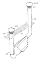
上述の自然サーモキャリアの熱作動で対流する放熱システムに関するものである。その開放型の熱作動及び放熱する循環システム構造は、更に図25及び図26に示す通り、丸形又はその他幾何形状の異なる穴直径があるパイプ構造で相互に嵌めて構成される。又、両者の間に断熱構造を設けるか、直接断熱材料で構成し、異なる穴直径があるパイプ形状の構造を嵌めることで、多重パイプ構造の開放式流体の配管構造が構成される。それは、少なくとも1セットのパイプ直径がより小さい配管をパイプ直径がより大きいパイプの中に嵌めて設けて、パイプ直径がより小さい配管の内部パイプのトップ部の封鎖端面1307の底部から、パイプ直径がより大きい外部パイプ壁にガイドフローパイプ1309を貫通して設けることで、より低い温度の流体を導入して、能動熱作動器108まで下げる。パイプ直径がより大きい配管を通して、より高い温度の流体を上昇して排出させる。2種の異なるパイプ直径がある配管の底部が共同で自然サーモキャリアの中の能動熱作動器108と繋がることで、開放型の放熱システムが構成される。又、能動熱作動器の外部に必要によって熱伝導フィン1001を増設して、その内部に逆流を防止する止め板1002を設けることができる。その中で、自然サーモキャリア101に設置される能動熱作動器108は、より大きい穴直径がある外部パイプ1301及び外部パイプ1301の底部の封鎖端面1302で構成され、又、必要によって熱伝導フィン1001を増設することで、自然サーモキャリアとの熱伝導効果を増進する。その内部に1セット又は1セット以上の穴直径がより小さい内部パイプ1303が設けられ、その内部パイプ1303の底部1304と外部パイプの底部の内部空間の間にガイドフローの隙間1305を設けることで、より低い温度の熱交換流体104が内部パイプ1303に入って、加熱された後、外部パイプ1301を通して上に流動することで、開放型の放熱システムが構成されるのである。
The present invention relates to a heat dissipation system that convects by the thermal operation of the natural thermocarrier described above. As shown in FIGS. 25 and 26, the open-type thermal operation and heat-dissipating circulation system structure is constructed by fitting together with pipe structures having round holes or other geometrically different hole diameters. Also, by providing a heat insulating structure between them or by directly forming a heat insulating material and fitting a pipe-shaped structure with different hole diameters, a multi-pipe open fluid piping structure is formed. That is, at least one set of pipes with a smaller pipe diameter is fitted into a pipe with a larger pipe diameter, and the pipe diameter is increased from the bottom of the
図25で示されるのは、能動熱作動器108又は熱交換流体が異なる穴直径があるパイプ構造を嵌めることで構成される開放型の放熱システムの構造例の斜視図である。図26は、図25の断面図である。上述の図25及び図26で示される異なる穴直径があるパイプ構造を嵌めることで構成される開放型の流体の配管構造は、更に、図27及び図28のように封鎖型のシステムを構成することができる。
FIG. 25 shows a perspective view of an example of a structure of an open type heat dissipation system configured by fitting an
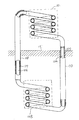
図27は、本発明の能動熱作動器108又は能動放熱器201が異なる穴直径を呈するパイプ構造で嵌めて構成する封鎖型放熱システム構造例の斜視図である。図28は、図27の断面図である。図27及び図28の中で、その主要な構造は、更に丸形又はその他幾何形状の異なる穴直径があるパイプ構造で相互に嵌めさせる断熱効果がある多重パイプ構造で構成される。それは、少なくとも1セットのパイプ直径がより小さい配管をパイプ直径がより大きいパイプの中に嵌めて設けて、パイプ直径がより小さい配管により低い温度の流体を下げてから導入する。及び、パイプ直径がより大きい流路を通して、相対的により高い温度の流体を上昇して排出させる。2種の異なるパイプ直径がある配管の底部が、共同で自然サーモキャリア101に設けられる能動熱作動器108と繋がる。又、そのトップ部が、共同でその上に設けられる能動放熱器201と繋がる。又、放熱を受ける温度差体103に放熱を行なう能動放熱器201は、より大きい穴直径がある外部パイプ1301及び外部パイプ1301のトップ部の封鎖端面1306で形成され、その内部に1セット又は1セット以上の穴直径がより小さい内部パイプ1303を設けることで、内部パイプ1303のトップ部の端面1310との間にガイドフローホールの経路1308を設けて、より高い温度の熱交換流体104が内部パイプ1303に沿って上に流動する。又、放熱して温度を下げた後、その外部パイプ1301に沿って下げてから、内部パイプ1303を通して上に上昇することで、封鎖型の放熱システムが構成されるのである。又、能動熱作動器108及び能動放熱器201は、必要によって、その外部に熱伝導フィン1001を増設して、その内部に熱伝導及び逆流を防止する止め板を設けることができる。
上述の自然サーモキャリアの熱作動で対流する放熱システムの封鎖型の熱作動及び放熱する循環システム構造は、更に図29及び図30の示す通り、丸型又はその他幾何形状のパイプ構造をループ形状パイプに貫通して設けることで構成される。又、両者の間に断熱構造を設けるか、直接断熱材料で構成するので、断熱の効果がある。
FIG. 27 is a perspective view of an example of a sealed heat radiation system structure in which the active
As shown in FIGS. 29 and 30, the above-described closed-type heat operation and heat-dissipation circulation system structure of the heat dissipating system that convects by the heat operation of the natural thermocarrier is a loop-shaped pipe. It is constituted by being provided through. In addition, since a heat insulating structure is provided between them or a direct heat insulating material is used, there is an effect of heat insulation.
図29は、本発明の能動熱作動器108を、より小さい穴直径のパイプ形状構造の配管をループ形状のパイプに貫通して設けることで構成される配管の内穴と結び付けることで構成される開放型放熱システム構造例の斜視図である。図30は、図29の断面図である。図29及び図30の中で、その主要な構成は、丸形又はその他幾何形状を呈するパイプ構造体の配管がループ形状パイプ構造体を呈する配管との間で断熱効果があり、それを貫通して結び付けることで構成されるのである。それは、少なくとも1セットのパイプ直径がより小さい配管332をループ形状のパイプで構成される配管333の内穴に貫通して設けて、両者の間は直接接触又は選定された隙間があっても良く、パイプ直径がより小さい配管332がより低い温度の温度差体102からより低い温度の流体を導入して下げてから、能動熱作動器108に導入する。又、ループ形状のパイプで構成される配管333は、能動熱作動器108によって加熱するより高い温度の流体を放熱受ける温度差体103を自然サーモキャリア101に導入する。又、2種の配管の底部が共同で自然サーモキャリア101の中の能動熱作動器108と繋がることで、開放型の放熱システムが構成される。又、能動熱作動器108は、必要によってその外部に熱伝導フィン1001を増設して、その内部に逆流を防止する止め板を設けることができる。
FIG. 29 is constructed by connecting the active
上述の図29及び図30で示される開放型放熱システムは、更に図31及び図32に示す通りに構成される封鎖型放熱システムを使っても良いのである。
図31は、本発明の能動熱作動器108及び能動放熱器201の間に、より小さい穴直径のパイプ形状構造の配管を、ループ形状のパイプに貫通して設けることで構成される配管の内穴が、共同で構成する封鎖型放熱システム構造例の斜視図である。図32は、図31の断面図である。図31及び図32の中で、その主要な構成は、丸形又はその他幾何形状を呈するパイプ構造体の配管がループ形状パイプ構造体を呈する配管との間に断熱効果があり、それを貫通して結び付ることで構成されるのである。それは、少なくとも1セットのパイプ直径がより小さい配管332をループ形状のパイプで構成される配管333の内穴に貫通して設けて、両者の間は直接接触、選定された隙間又は選定された充填物があっても良い。又、2種の配管106とその接触する自然サーモキャリア101との間に良い断熱構造109を備えるべきであり、又は、直接良い断熱材料で配管を構成する。パイプ直径がより小さい配管332が、より低い温度の流体を導入して下げてから、能動熱作動器108に導入する。又、ループ形状のパイプで構成される配管333に能動熱作動器108によって加熱するより高い温度の流体を上昇させて、能動放熱器201に導入する。又、2種の配管の底部が共同で自然サーモキャリア101の中の能動熱作動器108と繋がり、2種の配管のトップ部が共同でその上に設けられる能動放熱器201と繋がる。又、放熱を受ける温度差体103の放熱を提供する能動放熱器201は、ループ形状のパイプで構成される配管333のトップ部の封鎖端面334で拡大して形成され、能動放熱器201の下側は、1セット又は1セット以上の穴直径がより小さい配管332のトップのガイドフローホール335と繋がることで、熱交換流体104が能動放熱器201で放熱して温度を下げてから、配管332に沿って下げてから温度を下げた後、その外部パイプ1301に沿って下げてから、能動熱作動器108に流れて戻ることで、封鎖型の放熱システムが構成されるのである。又、能動熱作動器108及び能動放熱器201は、必要によってその外部に熱伝導フィン1001を増設して、その内部に熱伝導及び逆流を防止する止め板を設けることができる。
The open-type heat dissipation system shown in FIGS. 29 and 30 may be a sealed-type heat dissipation system configured as shown in FIGS. 31 and 32.
FIG. 31 shows the inside of a pipe constructed by providing a pipe having a pipe-shaped structure with a smaller hole diameter penetrating a loop-shaped pipe between the active
この自然サーモキャリアの熱作動で対流する放熱システムは、更に交差する丸型又はその他幾何形状のパイプ構造で構成される開封型又は封鎖型の放熱システムを呈することもできる。図33は、本発明の能動熱作動器の複数セットのパイプ形状の構造を交差して設けることで構成される開放型放熱システム構造例の斜視図である。図34は、図33の断面図である。図33及び図34で示される自然サーモキャリアの熱作動で対流する放熱システムは、更に丸形又はその他幾何形状を呈するパイプ形状の同一サイズ又は異なるサイズの複数セットのパイプ形状の構造を交差して設けることで構成される開放型流体の配管構造を使っても良いのである。それは、少なくとも1セットの導入口がより低い流体の配管によって、より低い温度の流体を下げてから導入することを提供し、又、少なくとも1セットの排出口がより高い流体の配管によって、相対的により高い温度の流体を上昇してから排出することを提供する。又、2種の配管106とその接触する自然サーモキャリア101との間に良い断熱構造109を備えるか、直接良い断熱材料で配管を構成する。2種の配管の底部が共同で自然サーモキャリアの中の能動熱作動器108と繋がることで、開放型の自然サーモキャリアの熱作動で対流する放熱システムが構成される。又、能動熱作動器108の外部に必要によって熱伝導フィン1001を増設して、その内部に逆流を防止する止め板を設けることができる。
The heat dissipating system that convects by the thermal operation of the natural thermocarrier can also be an open or sealed heat dissipating system constituted by intersecting round or other geometrical pipe structures. FIG. 33 is a perspective view of an open-type heat dissipation system structure example configured by crossing a plurality of sets of pipe-shaped structures of the active heat actuator of the present invention. 34 is a cross-sectional view of FIG. The heat dissipation system for convection by the thermal operation of the natural thermocarrier shown in FIG. 33 and FIG. 34 further intersects multiple sets of pipe-shaped structures of the same or different sizes in a pipe shape exhibiting a round shape or other geometric shapes. It is also possible to use an open type fluid piping structure that is provided. It provides that at least one set of inlets lowers and introduces the lower temperature fluid by lower fluid piping, and at least one set of outlets is relatively higher by higher fluid piping. Provides for higher temperature fluids to rise and then drain. Further, a good
上述の図33及び図34で示される複数セットのパイプ形状の構造は、更に封鎖型の流体配管構造を構成することもできる。
図35は、本発明の能動熱作動器又は能動放熱器の複数セットのパイプ形状の構造を交差して設けることで構成される封鎖型放熱システム構造例の斜視図である。図36は、図35の断面図である。図35及び図36では、能動熱作動器と能動放熱器を複数セットのパイプ形状の構造と結び付けてから、交差して設けることで構成される封鎖型放熱システムを使っても良いのである。その主要な構造は、丸形又はその他幾何形状を呈するパイプ形状の同一サイズ又は異なるサイズの配管、能動熱作動器108及び能動放熱器201で構成される。それは、少なくとも1セットの導入口がより低い流体の配管によって、温度差体102より低い温度の流体を下げてから能動熱作動器108に導入する。又、少なくとも1セットの排出口がより高い流体の配管によって、能動熱作動器108で加熱するより高い温度の流体を上昇してから、能動放熱器201に導入することで、放熱を受ける温度差体103に放熱を行なう。又、2種の配管106とその接触する自然サーモキャリア101との間に良い断熱構造109を備えるか、直接良い断熱材料で配管を構成する。2種の配管の底部が共同で自然サーモキャリア101の中の能動熱作動器108と繋がることで、及びそのトップ部が共同でその上に設けられる能動放熱器201と繋がることで、封鎖型の自然サーモキャリアの熱作動で対流する放熱システムが構成される。又、能動熱作動器の外部に必要によって熱伝導フィン1001を増設して、その内部に逆流を防止する止め板を設けることができる。
The plurality of sets of pipe-shaped structures shown in FIGS. 33 and 34 described above can further constitute a sealed fluid piping structure.
FIG. 35 is a perspective view of an example of a sealed heat radiation system structure configured by crossing a plurality of sets of pipe-shaped structures of the active thermal actuator or active heat radiator of the present invention. 36 is a cross-sectional view of FIG. 35 and 36, it is possible to use a sealed heat radiation system constituted by connecting an active thermal actuator and an active heat radiator to a plurality of sets of pipe-shaped structures and then crossing them. Its main structure is composed of pipes of the same size or different sizes in a pipe shape having a round shape or other geometric shapes, an active
前述の各種の能動熱作動器108又は能動放熱器201は、必要によって構造形態を選べ、同一幾何形状の構造で構成するか、又は、異なる幾何形状の構造形態と混合で構成しても良いのである。
The above-mentioned various active
本発明のシステムを応用する場合、管理及び制御を行なうため、必要によって下記のような装置を選んで設けることができる。
流量計は、交換流体の流量を累積で計算できる。この装置は、必要によって設けることができる。
When the system of the present invention is applied, the following devices can be selected and provided as necessary for management and control.
The flow meter can calculate the flow rate of the replacement fluid cumulatively. This device can be provided if necessary.
ろ過装置2001は、長い時間が経つために塞がることを防止でき、清潔の機能もあるろ過装置である。それを流体の吸入口又は出口に取り付けて、ろ過ネット及び有害流体のろ過装置で構成されるものである。
The
保護キャップの構造2002は、配管の排出口又は進入口の端に設けられるので、熱交換流体の流動性を比較的妨害しない保護キャップの構造である。それを配管に垂直又は上に伸びて設置する場合、雨水又は異物が落ちることを防止することができる。
Since the
流量の調節バルブは、人工又は機械で交換流量又は放熱量を制御するものである。
湿度の調整装置又は湿度の処理構造は、湿度の検知装置、排出ポンプセット、又は、配管に予め設けられる排出穴の湿度又は溜まる水の処理構造で構成されるものである。この装置は、その流体が気体である場合に選んで設けることができる。
The flow rate adjusting valve controls an exchange flow rate or a heat radiation amount by an artificial or a machine.
The humidity adjusting device or the humidity processing structure is configured with a humidity detecting device, a discharge pump set, or a processing structure for the humidity of the drain hole or the accumulated water provided in advance in the piping. This device can be selected and provided when the fluid is a gas.
制御ユニットは、機電又は固体電子電気回路及び関連するソフトで構成され、その機能は必要によって流体流量の制御、バルブの制御、流体温度の監視制御、流体ポンプの制御及び安全保護制御の機能を選ぶことができる。又、入力側又はそれぞれの出力側に有害流体の検知装置を設けることで、有害流体の存在がすでに監視値を超える場合、アラームを出して、気流を切断し、又は、その他制御対応策の処理を行なえる。上述によって、温度、交換気流の流量及び湿度などを調整及び制御できる機能が構成される。 The control unit is composed of electromechanical or solid-state electronic circuit and related software, and its function selects the function of fluid flow control, valve control, fluid temperature monitoring control, fluid pump control and safety protection control as required be able to. In addition, by installing a hazardous fluid detection device on the input side or on each output side, if the presence of harmful fluid already exceeds the monitored value, an alarm is issued, airflow is cut off, or other control measures are processed Can be done. By the above, the function which can adjust and control temperature, the flow volume of exchange airflow, humidity, etc. is comprised.
実際に応用する場合、本発明の自然サーモキャリアの熱作動で対流する放熱システムについて、熱交換流体は気体又は液体を含むのである。又、温度差体102及び放熱を受ける温度差体103は、下記のものを含む。 In actual application, for the heat dissipation system that convects by the thermal operation of the natural thermocarrier of the present invention, the heat exchange fluid contains a gas or a liquid. Moreover, the temperature difference body 102 and the temperature difference body 103 which receives heat dissipation include the following.
(1)固定の建築がある空調空間であり、例えば、ビル、温室又は公共活動の建物。
(2)空調の必要な空間であり、その空間は流体式の温度差体が動いている建物の中にあることが必要であり、例えば、船、浮かぶ作業台又は水上建築など。
(1) An air-conditioned space with a fixed architecture, such as a building, a greenhouse or a public activity building.
(2) It is a space that needs air conditioning, and the space needs to be in a building in which a fluid temperature difference body is moving, such as a ship, a floating work table, or a floating structure.
(3)気体又は液体を受ける露天空間であり、例えば、池、谷、盆地又は砂漠などの開放空間。
(4)気体又は液体を受ける密封の容器であり、例えば、気体又は液体を貯蔵する容器。
(3) An open space for receiving gas or liquid, for example, open spaces such as ponds, valleys, basins or deserts.
(4) A sealed container that receives gas or liquid, for example, a container that stores gas or liquid.
(5)それぞれの製造プロセス又は、処理プロセスを行なう設備である。
(6)受動的に氷が張ることを防止、又は、自発的に氷を除去する機械又は家電設備である。
(5) Equipment for performing each manufacturing process or processing process.
(6) A machine or home appliance that prevents ice from passively spreading or removes ice spontaneously.
(7)受動的に氷が張ることを防止、又は、自発的に氷を除去する開放的な路面、空港の滑走路又は水面の航路である。
(8)港、湖又は川の水道の表層及び温度差の深層である。
(7) It is an open road surface, airport runway or water surface route that passively prevents ice from spreading or voluntarily removes ice.
(8) The surface layer of the water supply of a port, a lake or a river, and the deep layer of a temperature difference.
(9)特定の地質であり、例えば、砂漠及びその周辺の環境など。
この自然サーモキャリアの熱作動で対流する放熱システムは、下記のような補助システムを拡大又は増設することができる。その含むものは、下記の通りである。
(9) Specific geology, such as the desert and surrounding environment.
In the heat dissipation system that convects by the thermal operation of the natural thermocarrier, the following auxiliary system can be expanded or added. The inclusions are as follows.
1.場所の需要又は経済的な利益のため、熱交換流体の排出口に流体を動かせるターボを増設することで、回転の機能の出力を生じさせて、発電機又はその他の負荷を駆動するものである。 1. For location demand or economic benefit, add a turbo that can move the fluid to the outlet of the heat exchange fluid to drive the output of the rotation function and drive the generator or other load .
2.機能の増強及び効果のサポートを必要とする場合、熱作動で対流する装置の進入口、排出口又は流路の中に、必要によって補助の流体ポンプを増設することができる。それは、自然環境の流動エネルギーを使う熱作動型、太陽エネルギー発電の熱作動型又は別に補助電力を増設する流体ポンプで駆動するものを含むのである。 2. If it is necessary to enhance the function and support the effect, an auxiliary fluid pump can be added in the inlet, outlet or flow path of the thermally convection device as necessary. It includes those that are driven by fluid pumps that use thermal energy that uses fluid energy in the natural environment, those that use solar energy, or those that add additional auxiliary power.
3.機能の増強及び効果のサポートを必要とする場合、熱作動で対流する装置の中に必要によって流体の加熱装置を増設することができる。
4.下に流れる流体の配管106及び上に流れる流体の配管107の内部は、手すり及び梯子として上下に配列する横の長方形を呈する構造を使っても良いのである。
3. When it is necessary to enhance the function and support the effect, it is possible to add a fluid heating device as necessary in the convection device by heat operation.
4). The inside of the piping 106 of the fluid flowing down and the piping 107 of the fluid flowing up may use a structure having a horizontal rectangle arranged vertically as a handrail and a ladder.
5.下に流れる流体の配管106及び上に流れる流体の配管107は、傾く構造を呈し、人が歩ける階段を設けている構造を使っても良いのである。
6.上に流れる流体の配管107の出口及び下に流れる流体の配管106の入口は、必要によって保護ネット又は保護カバーを増設することができる。
5. The downwardly flowing
6). If necessary, a protective net or a protective cover can be added to the outlet of the
100 熱作動で対流する装置、101 自然サーモキャリア、102 温度差体、103 放熱を受ける温度差体、104 熱交換流体、106 下に流れる流体の配管、107 上に流れる流体の配管、108 能動熱作動器、109 断熱構造、111 配管の進入口、112 配管の排出口、200 ∩形状の放熱対流装置、201 能動放熱器、202 熱伝導フィン、212 下端の出口、221 上がる流体の配管、222 下げる流体の配管、332 パイプ直径がより小さい配管、333 ループ形状のパイプで構成される配管、334 ループ形状のパイプで構成される配管のトップ部の封鎖端面、335 穴直径がより小さい配管のトップ部のガイドフローホール、1001 熱伝導フィン、1002 止め板、1301 外部パイプ、1302 外部パイプの底部の封鎖端面、1303 内部パイプ、1304 内部パイプの底部、1305 ガイドフローの隙間、1306 外部パイプのトップ部の封鎖端面、1307 内部パイプのトップ部の封鎖端面、1308 ガイドフローホールの経路、1309 ガイドフローパイプ、1310 内部パイプのトップ部、2001 ろ過装置、2002 保護キャップの構造
DESCRIPTION OF
Claims (7)
熱貯蔵がより安定する地層、地表、池、湖、川、砂漠、氷山又は海洋などの固体又は液体のサーモキャリアに能動熱作動器を設けて、能動熱作動器の両端にそれぞれ流体の配管を設けることで、それぞれ温度差体及び放熱を受ける温度差体に流れ、熱作動で対流する装置を構成し、熱作動で対流する装置を通して、温度差体より進入口配管から能動熱作動器(108)に入るより低い温度の流体が加温されるので、流体の寒い時下がり、暑い時上がる特性を利用して、対流機能を生じさせ、又、出口配管から放熱を受ける温度差体に流れることで、開放型の放熱システムが構成され、或いは、配管を通して能動放熱器(201)に流してから、再び配管を通して能動熱作動器(108)に流れて戻ることで、封鎖型の放熱システムが構成され、
その構造の特徴は下記のものを含み、
自然サーモキャリア(101)は、熱貯蔵がより安定する地層、地表、池、湖、川、砂漠、氷山又は海洋などの固体又は液体のサーモキャリアであり、
温度差体(102)は、より低い温度の気体、固体又は液体に関するものであり、それを常態で熱交換流体(104)と接触させることで、相互に均等な熱伝導を行なえるものであり、
放熱を受ける温度差体(103)は、気体、固体又は液体で構成される特定の機能空間又は構造であり、それによって、システムの運転中、直接又は間接で能動熱作動器で加温される熱交換流体で釈放されるサーモエネルギーの気体、固体又は液体を受けるものであり、それは屋根、路面、温室、水池、加温又は凍結防止の構造体で構成されるものであり、
熱交換流体(104)は、熱貯蔵及び熱伝導の性質を有する気体又は液体で構成するものを含み、又、それを常態で温度差体(102)と接触させることで、相互に均等な熱伝導を行なえるものであり、
熱作動で対流する装置(100)は、少なくとも1個のより低い熱交換流体が下に流れる流体の配管(106)に流れていくことを提供することで、自然サーモキャリアの中に設けられる少なくとも1個の能動熱作動器(108)の底部と繋がるもの、及び少なくとも1個の加温した後の熱交換流体(104)が上に流れる流体の配管(107)を提供することで、能動熱作動器(108)の上方流体の出口と繋がるもので構成されるものであり、
流体の配管(106)及び流体の配管(107)は、丸形又はその他幾何形状を呈するパイプ形状の構造物又は建築の構造体で構成され、又は、自然サーモキャリアの中の通路で構成され、下に流れる流体の配管(106)とその接触する自然サーモキャリア(101)との間に断熱構造(109)を備え、或いは、直接断熱材料で配管を構成し、その中で、少なくとも1個の下に流れる流体の配管(106)は、より低い温度の熱交換流体(104)が下に流れる流体の配管(106)の進入口(111)を経由してから、熱作動で対流する装置(100)の能動熱作動器(108)のより低い部分に入ることを提供し、又、少なくとも1個の上に流れる流体の配管(107)が、熱作動で対流する装置(100)の能動熱作動器(108)の上端から放熱を受ける温度差体(103)に流すことで、熱交換流体(104)を上に流れる流体の配管の排出口(112)を経由して、放熱を受ける温度差体(103)に排出するものであり、
能動熱作動器(108)は、熱作動で対流する装置(100)のより低い所に設けられ、その材料は、熱伝導特性がある材料であり、又、自然サーモキャリア(101)と熱伝導状態の構造形態を維持し、又は、直接自然サーモキャリア(101)の内部に流体を流通させる空間を利用して、直接能動熱作動器の機能を構成することで、前述の熱伝導特性の材料で作られる能動熱作動器(108)の代わりとして使われ、能動熱作動器のケースは更に熱伝導フィンを増設し、
更に丸形又はその他幾何形状のパイプ構造をループ形状パイプに貫通して設けることで構成され、又、両者の間に断熱構造を設けるか、直接断熱材料で構成し、その構成は、丸形又はその他幾何形状を呈するパイプ構造体の配管がループ形状パイプ構造体を呈する配管との間で断熱効果があり、それを貫通して結び付けることで構成され、
それは、少なくとも1セットのパイプ直径がより小さい配管(332)をループ形状のパイプで構成される配管(333)の内穴に貫通して設けて、両者は直接接触し又は両者の間に選定された隙間が形成され、パイプ直径がより小さい配管(332)がより低い温度の温度差体(102)からより低い温度の流体を導入して下げてから、能動熱作動器(108)に導入し、
又、ループ形状のパイプで構成される配管(333)に、能動熱作動器(108)によって加熱するより高い温度の流体を放熱受ける温度差体(103)を自然サーモキャリア(101)に導入し、
又、2種の配管の底部が共同で自然サーモキャリア(101)の中の能動熱作動器(108)と繋がることで、開放型の放熱システムが構成され、
又、能動熱作動器(108)がその外部に熱伝導フィン(1001)を増設して、その内部に逆流を防止する止め板を設置することを特徴とする自然サーモキャリアの熱作動で対流する放熱システム。 It is a heat dissipation system that convects with the thermal operation of a natural thermocarrier,
Provide active thermal actuators on solid or liquid thermocarriers such as geological layers, surface, ponds, lakes, rivers, deserts, icebergs or oceans where heat storage is more stable, and fluid pipings at both ends of the active thermal actuators. By providing them, a device that flows through the temperature difference body and the temperature difference body that receives heat radiation and convects by thermal operation is configured, and through the device that convects by thermal operation, the active thermal actuator (108 ) The lower temperature fluid entering is heated, so the convection function is generated using the characteristics of the fluid falling when it is cold and rising when it is hot, and it flows to the temperature difference body that receives heat from the outlet pipe. Thus, an open-type heat dissipation system is configured, or a closed-type heat dissipation system is configured by flowing through the pipe to the active heat radiator (201) and then flowing back through the pipe to the active heat actuator (108). Is
The features of the structure include:
The natural thermocarrier (101) is a solid or liquid thermocarrier such as a formation, surface, pond, lake, river, desert, iceberg or ocean where heat storage is more stable,
The temperature difference body (102) relates to a gas, solid or liquid at a lower temperature, and can contact the heat exchange fluid (104) in a normal state to conduct heat conduction equally to each other. ,
The temperature difference body (103) that receives heat is a specific functional space or structure composed of a gas, a solid, or a liquid, so that it is heated directly or indirectly by an active thermal actuator during system operation. Receives thermal energy gas, solid or liquid released by heat exchange fluid, which consists of roof, road surface, greenhouse, water pond, warming or anti-freezing structure,
The heat exchange fluid (104) includes those composed of a gas or a liquid having the properties of heat storage and heat conduction, and is brought into contact with the temperature difference body (102) in a normal state, so that the heat exchange fluid is evenly heated. Can conduct,
The thermally actuated convection apparatus (100) provides at least one lower heat exchange fluid to flow into the flowing fluid piping (106), thereby providing at least a natural thermocarrier. Providing a fluid line (107) over which the bottom of one active heat actuator (108) and at least one heat exchange fluid (104) after warming flow is provided, It consists of what connects with the outlet of the upper fluid of an actuator (108),
The fluid piping (106) and the fluid piping (107) are constructed of pipe-like structures or architectural structures that exhibit a round or other geometric shape, or consist of passages in a natural thermocarrier, comprising a adiabatic structure (109) between the pipe of the fluid flowing down the (106) and the natural thermo carrier (101) to the contact, or constitute a pipe directly adiabatic material, wherein at least 1 The lower fluid piping (106) is convected by thermal actuation after passing through the inlet (111) of the lower temperature heat exchange fluid (104) through the lower fluid piping (106). Of the device (100) that provides entry into the lower part of the active thermal actuator (108) of the device (100) and that the fluid piping (107) flowing over at least one of the devices (100) is convectively thermally activated. Active thermal actuator (108 The temperature difference body (103) that receives heat radiation through the discharge port (112) of the pipe of the fluid that flows upward through the heat exchange fluid (104) by flowing the temperature difference body (103) that receives heat radiation from the upper end of the Is to be discharged
Active heat actuator (108) is provided on the lower at the device for convection heat activated (100), the material is a material that is heat transfer characteristics, also, heat conduction and natural thermo carrier (101) The material having the above-described heat conduction characteristics is configured by directly configuring the function of the active thermal actuator using the space in which the fluid is allowed to flow directly inside the natural thermocarrier (101) while maintaining the structural form of the state. Is used as an alternative to the active thermal actuator (108) made in the
Consists of providing further through the pipe structure of round or other geometric shapes in a loop shape pipe, also either providing a heat insulating structure between them, constituted directly by a heat insulating material, its structure is round or other piping pipe structure exhibiting a geometry has thermal insulation between the pipe exhibiting a loop shape pipe structure, is composed of a tying therethrough,
It is provided with at least one set of pipes (332) having a smaller pipe diameter penetrating through the inner hole of the pipe (333) composed of loop-shaped pipes, and both are in direct contact or selected between the two. A pipe having a smaller pipe diameter (332) is introduced and lowered from the lower temperature differential (102) before being introduced into the active thermal actuator (108). ,
In addition, a temperature difference body (103) that receives heat from a higher temperature fluid heated by the active thermal actuator (108) is introduced into the natural thermocarrier (101) in the pipe (333) composed of a loop-shaped pipe. ,
Also, the bottom of the two types of pipes are jointly connected to the active thermal actuator (108) in the natural thermocarrier (101), so that an open type heat dissipation system is configured.
Further, the active thermal actuator (108) is convected by the thermal operation of a natural thermocarrier, characterized in that a heat conduction fin (1001) is added to the outside and a stop plate is installed inside the active thermal fin (1001). Heat dissipation system.
熱貯蔵がより安定する地層、地表、池、湖、川、砂漠、氷山又は海洋などの固体又は液体のサーモキャリアに能動熱作動器を設けて、能動熱作動器の両端にそれぞれ流体の配管を設けることで、それぞれ温度差体及び放熱を受ける温度差体に流れ、熱作動で対流する装置を構成し、熱作動で対流する装置を通して、温度差体より進入口配管から能動熱作動器(108)に入るより低い温度の流体が加温されるので、流体の寒い時下がり、暑い時上がる特性を利用して、対流機能を生じさせ、又、出口配管から放熱を受ける温度差体に流れることで、開放型の放熱システムが構成され、或いは、配管を通して能動放熱器(201)に流してから、再び配管を通して能動熱作動器(108)に流れて戻ることで、封鎖型の放熱システムが構成され、
その構造の特徴は下記のものを含み、
自然サーモキャリア(101)は、熱貯蔵がより安定する地層、地表、池、湖、川、砂漠、氷山又は海洋などの固体又は液体のサーモキャリアであり、
温度差体(102)は、より低い温度の気体、固体又は液体に関するものであり、それを常態で熱交換流体(104)と接触させることで、相互に均等な熱伝導を行なえるものであり、
放熱を受ける温度差体(103)は、気体、固体又は液体で構成される特定の機能空間又は構造であり、それによって、システムの運転中、直接又は間接で能動熱作動器で加温される熱交換流体で釈放されるサーモエネルギーの気体、固体又は液体を受けるものであり、それは屋根、路面、温室、水池、加温又は凍結防止の構造体で構成されるものであり、
熱交換流体(104)は、熱貯蔵及び熱伝導の性質を有する気体又は液体で構成するものを含み、又、それを常態で温度差体(102)と接触させることで、相互に均等な熱伝導を行なえるものであり、
熱作動で対流する装置(100)は、少なくとも1個のより低い熱交換流体が下に流れる流体の配管(106)に流れていくことを提供することで、自然サーモキャリアの中に設けられる少なくとも1個の能動熱作動器(108)の底部と繋がるもの、及び少なくとも1個の加温した後の熱交換流体(104)が上に流れる流体の配管(107)を提供することで、能動熱作動器(108)の上方流体の出口と繋がるもので構成されるものであり、
流体の配管(106)及び流体の配管(107)は、丸形又はその他幾何形状を呈するパイプ形状の構造物又は建築の構造体で構成され、又は、自然サーモキャリアの中の通路で構成され、下に流れる流体の配管(106)とその接触する自然サーモキャリア(101)との間に断熱構造(109)を備え、或いは、直接断熱材料で配管を構成し、その中で、少なくとも1個の下に流れる流体の配管(106)は、より低い温度の熱交換流体(104)が下に流れる流体の配管(106)の進入口(111)を経由してから、熱作動で対流する装置(100)の能動熱作動器(108)のより低い部分に入ることを提供し、又、少なくとも1個の上に流れる流体の配管(107)が、熱作動で対流する装置(100)の能動熱作動器(108)の上端から放熱を受ける温度差体(103)に流すことで、熱交換流体(104)を上に流れる流体の配管の排出口(112)を経由して、放熱を受ける温度差体(103)に排出するものであり、
能動熱作動器(108)は、熱作動で対流する装置(100)のより低い所に設けられ、その材料は、熱伝導特性がある材料であり、又、自然サーモキャリア(101)と熱伝導状態の構造形態を維持し、又は、直接自然サーモキャリア(101)の内部に流体を流通させる空間を利用して、直接能動熱作動器の機能を構成することで、前述の熱伝導特性の材料で作られる能動熱作動器(108)の代わりとして使われ、能動熱作動器のケースは更に熱伝導フィンを増設し、
更に能動熱作動器(108)及び能動放熱器(201)の間に、より小さい穴直径のパイプ構造の配管をループ形状パイプに貫通して設けることで構成され、その構成は、丸形又はその他幾何形状を呈するパイプ構造体の配管がループ形状パイプ構造体を呈する配管との間に断熱効果があり、それを貫通して結び付けることで構成され、
それは、少なくとも1セットのパイプ直径がより小さい配管(332)をループ形状のパイプで構成される配管(333)の内穴に貫通して設けて、両者は直接接触し又は両者の間に選定された隙間を有し又は前記隙間に選定された充填物があり、
又、2種の配管(106)とその接触する自然サーモキャリア(101)との間に断熱構造(109)を備え、或いは、直接断熱材料で配管を構成し、パイプ直径がより小さい配管(332)が、より低い温度の流体を導入して下げてから、能動熱作動器(108)に導入し、
又、ループ形状のパイプで構成される配管(333)に、能動熱作動器(108)によって加熱するより高い温度の流体を上昇させて、能動放熱器(201)に導入し、
又、2種の配管の底部が共同で自然サーモキャリア(101)の中の能動熱作動器(108)と繋がり、2種の配管のトップ部が共同でその上に設けられる能動放熱器(201)と繋がり、
又、放熱を受ける温度差体(103)の放熱を提供する能動放熱器(201)はループ形状のパイプで構成される配管(333)のトップ部の封鎖端面(334)で拡大して形成され、能動放熱器(201)の下側は、1セット以上の穴直径がより小さい配管(332)のトップのガイドフローホール(335)と繋がることで、熱交換流体(104)が能動放熱器(201)で放熱して温度を下げてから、配管(332)に沿って下げてから温度を下げた後、その外部パイプ(1301)に沿って下げてから、能動熱作動器(108)に流れて戻ることで、封鎖型の放熱システムが構成され、
又、能動熱作動器(108)及び能動放熱器(201)は、その外部に熱伝導フィン(1001)を増設して、その内部に熱伝導及び逆流を防止する止め板を設置することを特徴とする自然サーモキャリアの熱作動で対流する放熱システム。 It is a heat dissipation system that convects with the thermal operation of a natural thermocarrier,
Provide active thermal actuators on solid or liquid thermocarriers such as geological layers, surface, ponds, lakes, rivers, deserts, icebergs or oceans where heat storage is more stable, and fluid pipings at both ends of the active thermal actuators. By providing them, a device that flows through the temperature difference body and the temperature difference body that receives heat radiation and convects by thermal operation is configured, and through the device that convects by thermal operation, the active thermal actuator (108 ) The lower temperature fluid entering is heated, so the convection function is generated using the characteristics of the fluid falling when it is cold and rising when it is hot, and it flows to the temperature difference body that receives heat from the outlet pipe. Thus, an open-type heat dissipation system is configured, or a closed-type heat dissipation system is configured by flowing through the pipe to the active heat radiator (201) and then flowing back through the pipe to the active heat actuator (108). Is
The features of the structure include:
The natural thermocarrier (101) is a solid or liquid thermocarrier such as a formation, surface, pond, lake, river, desert, iceberg or ocean where heat storage is more stable,
The temperature difference body (102) relates to a gas, solid or liquid at a lower temperature, and can contact the heat exchange fluid (104) in a normal state to conduct heat conduction equally to each other. ,
The temperature difference body (103) that receives heat is a specific functional space or structure composed of a gas, a solid, or a liquid, so that it is heated directly or indirectly by an active thermal actuator during system operation. Receives thermal energy gas, solid or liquid released by heat exchange fluid, which consists of roof, road surface, greenhouse, water pond, warming or anti-freezing structure,
The heat exchange fluid (104) includes those composed of a gas or a liquid having the properties of heat storage and heat conduction, and is brought into contact with the temperature difference body (102) in a normal state, so that the heat exchange fluid is evenly heated. Can conduct,
The thermally actuated convection apparatus (100) provides at least one lower heat exchange fluid to flow into the flowing fluid piping (106), thereby providing at least a natural thermocarrier. Providing a fluid line (107) over which the bottom of one active heat actuator (108) and at least one heat exchange fluid (104) after warming flow is provided, It consists of what connects with the outlet of the upper fluid of an actuator (108),
The fluid piping (106) and the fluid piping (107) are constructed of pipe-like structures or architectural structures that exhibit a round or other geometric shape, or consist of passages in a natural thermocarrier, comprising a adiabatic structure (109) between the pipe of the fluid flowing down the (106) and the natural thermo carrier (101) to the contact, or constitute a pipe directly adiabatic material, wherein at least 1 The lower fluid piping (106) is convected by thermal actuation after passing through the inlet (111) of the lower temperature heat exchange fluid (104) through the lower fluid piping (106). Of the device (100) that provides entry into the lower part of the active thermal actuator (108) of the device (100) and that the fluid piping (107) flowing over at least one of the devices (100) is convectively thermally activated. Active thermal actuator (108 The temperature difference body (103) that receives heat radiation through the discharge port (112) of the pipe of the fluid that flows upward through the heat exchange fluid (104) by flowing the temperature difference body (103) that receives heat radiation from the upper end of the Is to be discharged
Active heat actuator (108) is provided on the lower at the device for convection heat activated (100), the material is a material that is heat transfer characteristics, also, heat conduction and natural thermo carrier (101) The material having the above-described heat conduction characteristics is configured by directly configuring the function of the active thermal actuator using the space in which the fluid is allowed to flow directly inside the natural thermocarrier (101) while maintaining the structural form of the state. Is used as an alternative to the active thermal actuator (108) made in the
Furthermore, it is configured by providing a pipe having a smaller hole diameter pipe through the loop-shaped pipe between the active heat actuator (108) and the active heat radiator (201). The piping of the pipe structure exhibiting a geometric shape has a heat insulating effect between the piping exhibiting the loop shape pipe structure, and is configured by piercing and linking it,
It is provided with at least one set of pipes (332) having a smaller pipe diameter penetrating through the inner hole of the pipe (333) composed of loop-shaped pipes, and both are in direct contact or selected between the two. and there is packing which is selected in the closed or the gap clearance,
Further, the two pipes (106) provided with adiabatic structure (109) between the natural thermo carrier (101) to the contact, or constitute a pipe directly adiabatic material, piping pipe diameter is less than (332) introduces and lowers the lower temperature fluid before introducing it into the active thermal actuator (108);
In addition, a higher temperature fluid heated by the active thermal actuator (108) is raised to the pipe (333) composed of a loop-shaped pipe, and is introduced into the active radiator (201).
Further, the bottoms of the two types of piping are jointly connected to the active thermal actuator (108) in the natural thermocarrier (101), and the tops of the two types of piping are jointly provided on the active heat radiator (201. )
In addition, the active radiator (201) that provides heat dissipation of the temperature difference body (103) that receives heat dissipation is formed to be enlarged at the sealed end face (334) of the top portion of the pipe (333) constituted by a loop-shaped pipe. The lower side of the active radiator (201) is connected to the top guide flow hole (335) of the pipe (332) having a smaller hole diameter of one or more sets, so that the heat exchange fluid (104) is 201) radiates heat to lower the temperature, then drops along the pipe (332), then lowers the temperature, then drops along its external pipe (1301), and then flows to the active thermal actuator (108) Back, a sealed heat dissipation system is configured,
Further, the active heat actuator (108) and the active heat radiator (201) are characterized in that a heat conduction fin (1001) is added to the outside, and a stop plate for preventing heat conduction and backflow is installed inside. A heat dissipation system that convects with the thermal action of a natural thermocarrier.
熱貯蔵がより安定する地層、地表、池、湖、川、砂漠、氷山又は海洋などの固体又は液体のサーモキャリアに能動熱作動器を設けて、能動熱作動器の両端にそれぞれ流体の配管を設けることで、それぞれ温度差体及び放熱を受ける温度差体に流れ、熱作動で対流する装置を構成し、熱作動で対流する装置を通して、温度差体より進入口配管から能動熱作動器(108)に入るより低い温度の流体が加温されるので、流体の寒い時下がり、暑い時上がる特性を利用して、対流機能を生じさせ、又、出口配管から放熱を受ける温度差体に流れることで、開放型の放熱システムが構成され、或いは、配管を通して能動放熱器(201)に流してから、再び配管を通して能動熱作動器(108)に流れて戻ることで、封鎖型の放熱システムが構成され、
その構造の特徴は下記のものを含み、
自然サーモキャリア(101)は、熱貯蔵がより安定する地層、地表、池、湖、川、砂漠、氷山又は海洋などの固体又は液体のサーモキャリアであり、
温度差体(102)は、より低い温度の気体、固体又は液体に関するものであり、それを常態で熱交換流体(104)と接触させることで、相互に均等な熱伝導を行なえるものであり、
放熱を受ける温度差体(103)は、気体、固体又は液体で構成される特定の機能空間又は構造であり、それによって、システムの運転中、直接又は間接で能動熱作動器で加温される熱交換流体で釈放されるサーモエネルギーの気体、固体又は液体を受けるものであり、それは屋根、路面、温室、水池、加温又は凍結防止の構造体で構成されるものであり、
熱交換流体(104)は、熱貯蔵及び熱伝導の性質を有する気体又は液体で構成するものを含み、又、それを常態で温度差体(102)と接触させることで、相互に均等な熱伝導を行なえるものであり、
熱作動で対流する装置(100)は、少なくとも1個のより低い熱交換流体が下に流れる流体の配管(106)に流れていくことを提供することで、自然サーモキャリアの中に設けられる少なくとも1個の能動熱作動器(108)の底部と繋がるもの、及び少なくとも1個の加温した後の熱交換流体(104)が上に流れる流体の配管(107)を提供することで、能動熱作動器(108)の上方流体の出口と繋がるもので構成されるものであり、
流体の配管(106)及び流体の配管(107)は、丸形又はその他幾何形状を呈するパイプ形状の構造物又は建築の構造体で構成され、又は、自然サーモキャリアの中の通路で構成され、下に流れる流体の配管(106)とその接触する自然サーモキャリア(101)との間に断熱構造(109)を備え、或いは、直接断熱材料で配管を構成し、その中で、少なくとも1個の下に流れる流体の配管(106)は、より低い温度の熱交換流体(104)が下に流れる流体の配管(106)の進入口(111)を経由してから、熱作動で対流する装置(100)の能動熱作動器(108)のより低い部分に入ることを提供し、又、少なくとも1個の上に流れる流体の配管(107)が、熱作動で対流する装置(100)の能動熱作動器(108)の上端から放熱を受ける温度差体(103)に流すことで、熱交換流体(104)を上に流れる流体の配管の排出口(112)を経由して、放熱を受ける温度差体(103)に排出するものであり、
能動熱作動器(108)は、熱作動で対流する装置(100)のより低い所に設けられ、その材料は、熱伝導特性がある材料であり、又、自然サーモキャリア(101)と熱伝導状態の構造形態を維持し、又は、直接自然サーモキャリア(101)の内部に流体を流通させる空間を利用して、直接能動熱作動器の機能を構成することで、前述の熱伝導特性の材料で作られる能動熱作動器(108)の代わりとして使われ、能動熱作動器のケースは更に熱伝導フィンを増設し、
更に丸形又はその他幾何形状を呈するパイプ形状の同一サイズ又は異なるサイズの複数セットのパイプ形状の構造を交差して設けることで構成される開放型流体の配管構造を使い、
それは、少なくとも1セットの導入口が、より低い流体の配管によって、より低い温度の流体を下げてから導入することを提供し、
又、少なくとも1セットの排出口が、より高い流体の配管によって、相対的により高い温度の流体を上昇してから排出することを提供し、
又、2種の配管(106)とその接触する自然サーモキャリア(101)との間に断熱構造(109)を備えるか、直接断熱材料で配管を構成し、2種の配管の底部が共同で自然サーモキャリアの中の能動熱作動器(108)と繋がることで、開放型の自然サーモキャリアの熱作動で対流する放熱システムが構成され、
又、能動熱作動器(108)の外部に熱伝導フィン(1001)を増設して、その内部に逆流を防止する止め板(1002)を設置することを特徴とする自然サーモキャリアの熱作動で対流する放熱システム。 It is a heat dissipation system that convects with the thermal operation of a natural thermocarrier,
Provide active thermal actuators on solid or liquid thermocarriers such as geological layers, surface, ponds, lakes, rivers, deserts, icebergs or oceans where heat storage is more stable, and fluid pipings at both ends of the active thermal actuators. By providing them, a device that flows through the temperature difference body and the temperature difference body that receives heat radiation and convects by thermal operation is configured, and through the device that convects by thermal operation, the active thermal actuator (108 ) The lower temperature fluid entering is heated, so the convection function is generated using the characteristics of the fluid falling when it is cold and rising when it is hot, and it flows to the temperature difference body that receives heat from the outlet pipe. Thus, an open-type heat dissipation system is configured, or a closed-type heat dissipation system is configured by flowing through the pipe to the active heat radiator (201) and then flowing back through the pipe to the active heat actuator (108). Is
The features of the structure include:
The natural thermocarrier (101) is a solid or liquid thermocarrier such as a formation, surface, pond, lake, river, desert, iceberg or ocean where heat storage is more stable,
The temperature difference body (102) relates to a gas, solid or liquid at a lower temperature, and can contact the heat exchange fluid (104) in a normal state to conduct heat conduction equally to each other. ,
The temperature difference body (103) that receives heat is a specific functional space or structure composed of a gas, a solid, or a liquid, so that it is heated directly or indirectly by an active thermal actuator during system operation. Receives thermal energy gas, solid or liquid released by heat exchange fluid, which consists of roof, road surface, greenhouse, water pond, warming or anti-freezing structure,
The heat exchange fluid (104) includes those composed of a gas or a liquid having the properties of heat storage and heat conduction, and is brought into contact with the temperature difference body (102) in a normal state, so that the heat exchange fluid is evenly heated. Can conduct,
The thermally actuated convection apparatus (100) provides at least one lower heat exchange fluid to flow into the flowing fluid piping (106), thereby providing at least a natural thermocarrier. Providing a fluid line (107) over which the bottom of one active heat actuator (108) and at least one heat exchange fluid (104) after warming flow is provided, It consists of what connects with the outlet of the upper fluid of an actuator (108),
The fluid piping (106) and the fluid piping (107) are constructed of pipe-like structures or architectural structures that exhibit a round or other geometric shape, or consist of passages in a natural thermocarrier, comprising a adiabatic structure (109) between the pipe of the fluid flowing down the (106) and the natural thermo carrier (101) to the contact, or constitute a pipe directly adiabatic material, wherein at least 1 The lower fluid piping (106) is convected by thermal actuation after passing through the inlet (111) of the lower temperature heat exchange fluid (104) through the lower fluid piping (106). Of the device (100) that provides entry into the lower part of the active thermal actuator (108) of the device (100) and that the fluid piping (107) flowing over at least one of the devices (100) is convectively thermally activated. Active thermal actuator (108 The temperature difference body (103) that receives heat radiation through the discharge port (112) of the pipe of the fluid that flows upward through the heat exchange fluid (104) by flowing the temperature difference body (103) that receives heat radiation from the upper end of the Is to be discharged
Active heat actuator (108) is provided on the lower at the device for convection heat activated (100), the material is a material that is heat transfer characteristics, also, heat conduction and natural thermo carrier (101) The material having the above-described heat conduction characteristics is configured by directly configuring the function of the active thermal actuator using the space in which the fluid is allowed to flow directly inside the natural thermocarrier (101) while maintaining the structural form of the state. Is used as an alternative to the active thermal actuator (108) made in the
Furthermore, using a pipe structure of an open-type fluid constituted by providing multiple sets of pipe-shaped structures of the same size or different sizes of pipe shapes exhibiting a round shape or other geometric shapes,
It provides that at least one set of inlets lowers and introduces the lower temperature fluid by lower fluid piping;
Also, at least one set of outlets provides higher fluid piping to raise and discharge the relatively higher temperature fluid,
Further, if provided with two pipe (106) the adiabatic structure (109) between the natural thermo carrier (101) to the contact, it constitutes a pipe directly adiabatic material, the bottom of the two pipes By jointly connecting with the active thermal actuator (108) in the natural thermocarrier, a heat dissipation system that convects by the thermal operation of the open natural thermocarrier is configured,
In addition, the thermal operation of the natural thermocarrier is characterized in that a heat conduction fin (1001) is added to the outside of the active thermal actuator (108), and a stop plate (1002) for preventing backflow is installed inside the fin. Convection heat dissipation system.
熱貯蔵がより安定する地層、地表、池、湖、川、砂漠、氷山又は海洋などの固体又は液体のサーモキャリアに能動熱作動器を設けて、能動熱作動器の両端にそれぞれ流体の配管を設けることで、それぞれ温度差体及び放熱を受ける温度差体に流れ、熱作動で対流する装置を構成し、熱作動で対流する装置を通して、温度差体より進入口配管から能動熱作動器(108)に入るより低い温度の流体が加温されるので、流体の寒い時下がり、暑い時上がる特性を利用して、対流機能を生じさせ、又、出口配管から放熱を受ける温度差体に流れることで、開放型の放熱システムが構成され、或いは、配管を通して能動放熱器(201)に流してから、再び配管を通して能動熱作動器(108)に流れて戻ることで、封鎖型の放熱システムが構成され、
その構造の特徴は下記のものを含み、
自然サーモキャリア(101)は、熱貯蔵がより安定する地層、地表、池、湖、川、砂漠、氷山又は海洋などの固体又は液体のサーモキャリアであり、
温度差体(102)は、より低い温度の気体、固体又は液体に関するものであり、それを常態で熱交換流体(104)と接触させることで、相互に均等な熱伝導を行なえるものであり、
放熱を受ける温度差体(103)は、気体、固体又は液体で構成される特定の機能空間又は構造であり、それによって、システムの運転中、直接又は間接で能動熱作動器で加温される熱交換流体で釈放されるサーモエネルギーの気体、固体又は液体を受けるものであり、それは屋根、路面、温室、水池、加温又は凍結防止の構造体で構成されるものであり、
熱交換流体(104)は、熱貯蔵及び熱伝導の性質を有する気体又は液体で構成するものを含み、又、それを常態で温度差体(102)と接触させることで、相互に均等な熱伝導を行なえるものであり、
熱作動で対流する装置(100)は、少なくとも1個のより低い熱交換流体が下に流れる流体の配管(106)に流れていくことを提供することで、自然サーモキャリアの中に設けられる少なくとも1個の能動熱作動器(108)の底部と繋がるもの、及び少なくとも1個の加温した後の熱交換流体(104)が上に流れる流体の配管(107)を提供することで、能動熱作動器(108)の上方流体の出口と繋がるもので構成されるものであり、
流体の配管(106)及び流体の配管(107)は、丸形又はその他幾何形状を呈するパイプ形状の構造物又は建築の構造体で構成され、又は、自然サーモキャリアの中の通路で構成され、下に流れる流体の配管(106)とその接触する自然サーモキャリア(101)との間に断熱構造(109)を備え、或いは、直接断熱材料で配管を構成し、その中で、少なくとも1個の下に流れる流体の配管(106)は、より低い温度の熱交換流体(104)が下に流れる流体の配管(106)の進入口(111)を経由してから、熱作動で対流する装置(100)の能動熱作動器(108)のより低い部分に入ることを提供し、又、少なくとも1個の上に流れる流体の配管(107)が、熱作動で対流する装置(100)の能動熱作動器(108)の上端から放熱を受ける温度差体(103)に流すことで、熱交換流体(104)を上に流れる流体の配管の排出口(112)を経由して、放熱を受ける温度差体(103)に排出するものであり、
能動熱作動器(108)は、熱作動で対流する装置(100)のより低い所に設けられ、その材料は、熱伝導特性がある材料であり、又、自然サーモキャリア(101)と熱伝導状態の構造形態を維持し、又は、直接自然サーモキャリア(101)の内部に流体を流通させる空間を利用して、直接能動熱作動器の機能を構成することで、前述の熱伝導特性の材料で作られる能動熱作動器(108)の代わりとして使われ、能動熱作動器のケースは更に熱伝導フィンを増設し、
能動熱作動器と能動放熱器を複数セットのパイプ形状の構造と結び付けてから、交差して設けることで構成される封鎖型放熱システムを使い、その構造は、丸形又はその他幾何形状を呈するパイプ形状の同一サイズ又は異なるサイズの配管、能動熱作動器(108)及び能動放熱器(201)で構成され、
それは、少なくとも1セットの導入口が、より低い流体の配管によって、温度差体(102)より低い温度の流体を下げてから能動熱作動器(108)に導入し、
又、少なくとも1セットの排出口が、より高い流体の配管によって、能動熱作動器(108)で加熱するより高い温度の流体を上昇してから能動放熱器(201)に導入することで、放熱を受ける温度差体(103)に放熱を行い、
又、2種の配管(106)とその接触する自然サーモキャリア(101)との間に断熱構造(109)を備えるか、直接断熱材料で配管を構成し、2種の配管の底部が共同で自然サーモキャリア(101)の中の能動熱作動器(108)と繋がることで、及びそのトップ部が共同でその上に設けられる能動放熱器(201)と繋がることで、封鎖型の自然サーモキャリアの熱作動で対流する放熱システムが構成され、
又、能動熱作動器(108)の外部に熱伝導フィン(1001)を増設して、その内部に逆流を防止する止め板を設置することを特徴とする自然サーモキャリアの熱作動で対流する放熱システム。 It is a heat dissipation system that convects with the thermal operation of a natural thermocarrier,
Provide active thermal actuators on solid or liquid thermocarriers such as geological layers, surface, ponds, lakes, rivers, deserts, icebergs or oceans where heat storage is more stable, and fluid pipings at both ends of the active thermal actuators. By providing them, a device that flows through the temperature difference body and the temperature difference body that receives heat radiation and convects by thermal operation is configured, and through the device that convects by thermal operation, the active thermal actuator (108 ) The lower temperature fluid entering is heated, so the convection function is generated using the characteristics of the fluid falling when it is cold and rising when it is hot, and it flows to the temperature difference body that receives heat from the outlet pipe. Thus, an open-type heat dissipation system is configured, or a closed-type heat dissipation system is configured by flowing through the pipe to the active heat radiator (201) and then flowing back through the pipe to the active heat actuator (108). Is
The features of the structure include:
The natural thermocarrier (101) is a solid or liquid thermocarrier such as a formation, surface, pond, lake, river, desert, iceberg or ocean where heat storage is more stable,
The temperature difference body (102) relates to a gas, solid or liquid at a lower temperature, and can contact the heat exchange fluid (104) in a normal state to conduct heat conduction equally to each other. ,
The temperature difference body (103) that receives heat is a specific functional space or structure composed of a gas, a solid, or a liquid, so that it is heated directly or indirectly by an active thermal actuator during system operation. Receives thermal energy gas, solid or liquid released by heat exchange fluid, which consists of roof, road surface, greenhouse, water pond, warming or anti-freezing structure,
The heat exchange fluid (104) includes those composed of a gas or a liquid having the properties of heat storage and heat conduction, and is brought into contact with the temperature difference body (102) in a normal state, so that the heat exchange fluid is evenly heated. Can conduct,
The thermally actuated convection apparatus (100) provides at least one lower heat exchange fluid to flow into the flowing fluid piping (106), thereby providing at least a natural thermocarrier. Providing a fluid line (107) over which the bottom of one active heat actuator (108) and at least one heat exchange fluid (104) after warming flow is provided, It consists of what connects with the outlet of the upper fluid of an actuator (108),
The fluid piping (106) and the fluid piping (107) are constructed of pipe-like structures or architectural structures that exhibit a round or other geometric shape, or consist of passages in a natural thermocarrier, comprising a adiabatic structure (109) between the pipe of the fluid flowing down the (106) and the natural thermo carrier (101) to the contact, or constitute a pipe directly adiabatic material, wherein at least 1 The lower fluid piping (106) is convected by thermal actuation after passing through the inlet (111) of the lower temperature heat exchange fluid (104) through the lower fluid piping (106). Of the device (100) that provides entry into the lower part of the active thermal actuator (108) of the device (100) and that the fluid piping (107) flowing over at least one of the devices (100) is convectively thermally activated. Active thermal actuator (108 The temperature difference body (103) that receives heat radiation through the discharge port (112) of the pipe of the fluid that flows upward through the heat exchange fluid (104) by flowing the temperature difference body (103) that receives heat radiation from the upper end of the Is to be discharged
Active heat actuator (108) is provided on the lower at the device for convection heat activated (100), the material is a material that is heat transfer characteristics, also, heat conduction and natural thermo carrier (101) The material having the above-described heat conduction characteristics is configured by directly configuring the function of the active thermal actuator using the space in which the fluid is allowed to flow directly inside the natural thermocarrier (101) while maintaining the structural form of the state. Is used as an alternative to the active thermal actuator (108) made in the
A sealed heat dissipation system is used, in which active heat actuators and active heat sinks are combined with multiple sets of pipe-shaped structures and then crossed, and the structure is a round or other geometric pipe Consists of pipes of the same size or different sizes, active thermal actuator (108) and active radiator (201),
That is, at least one set of inlets lowers the lower temperature fluid than the temperature differential (102) by lower fluid piping before introducing it into the active thermal actuator (108);
In addition, at least one set of outlets raises the higher temperature fluid heated by the active thermal actuator (108) by higher fluid piping and then introduces it into the active heat radiator (201), thereby dissipating heat. To the temperature difference body (103) receiving the heat,
Further, if provided with two pipe (106) the adiabatic structure (109) between the natural thermo carrier (101) to the contact, it constitutes a pipe directly adiabatic material, the bottom of the two pipes By jointly connecting with the active thermal actuator (108) in the natural thermocarrier (101) and by connecting the top part with the active heat radiator (201) provided on the joint, the natural heat carrier (101) is sealed. A heat dissipation system that convects by the thermal operation of the thermocarrier is configured,
Further, heat conduction fins (1001) are added to the outside of the active thermal actuator (108) , and a stop plate for preventing backflow is installed in the inside of the heat conduction fins (1001). system.
熱貯蔵がより安定する地層、地表、池、湖、川、砂漠、氷山又は海洋などの固体又は液体のサーモキャリアに能動熱作動器を設けて、能動熱作動器の両端にそれぞれ流体の配管を設けることで、それぞれ温度差体及び放熱を受ける温度差体に流れ、熱作動で対流する装置を構成し、熱作動で対流する装置を通して、温度差体より進入口配管から能動熱作動器(108)に入るより低い温度の流体が加温されるので、流体の寒い時下がり、暑い時上がる特性を利用して、対流機能を生じさせ、又、出口配管から放熱を受ける温度差体に流れることで、開放型の放熱システムが構成され、或いは、配管を通して能動放熱器(201)に流してから、再び配管を通して能動熱作動器(108)に流れて戻ることで、封鎖型の放熱システムが構成され、
その構造の特徴は下記のものを含み、
自然サーモキャリア(101)は、熱貯蔵がより安定する地層、地表、池、湖、川、砂漠、氷山又は海洋などの固体又は液体のサーモキャリアであり、
温度差体(102)は、より低い温度の気体、固体又は液体に関するものであり、それを常態で熱交換流体(104)と接触させることで、相互に均等な熱伝導を行なえるものであり、
放熱を受ける温度差体(103)は、気体、固体又は液体で構成される特定の機能空間又は構造であり、それによって、システムの運転中、直接又は間接で能動熱作動器で加温される熱交換流体で釈放されるサーモエネルギーの気体、固体又は液体を受けるものであり、それは屋根、路面、温室、水池、加温又は凍結防止の構造体で構成されるものであり、
熱交換流体(104)は、熱貯蔵及び熱伝導の性質を有する気体又は液体で構成するものを含み、又、それを常態で温度差体(102)と接触させることで、相互に均等な熱伝導を行なえるものであり、
熱作動で対流する装置(100)は、少なくとも1個のより低い熱交換流体が下に流れる流体の配管(106)に流れていくことを提供することで、自然サーモキャリアの中に設けられる少なくとも1個の能動熱作動器(108)の底部と繋がるもの、及び少なくとも1個の加温した後の熱交換流体(104)が上に流れる流体の配管(107)を提供することで、能動熱作動器(108)の上方流体の出口と繋がるもので構成されるものであり、
流体の配管(106)及び流体の配管(107)は、丸形又はその他幾何形状を呈するパイプ形状の構造物又は建築の構造体で構成され、又は、自然サーモキャリアの中の通路で構成され、下に流れる流体の配管(106)とその接触する自然サーモキャリア(101)との間に断熱構造(109)を備え、或いは、直接断熱材料で配管を構成し、その中で、少なくとも1個の下に流れる流体の配管(106)は、より低い温度の熱交換流体(104)が下に流れる流体の配管(106)の進入口(111)を経由してから、熱作動で対流する装置(100)の能動熱作動器(108)のより低い部分に入ることを提供し、又、少なくとも1個の上に流れる流体の配管(107)が、熱作動で対流する装置(100)の能動熱作動器(108)の上端から放熱を受ける温度差体(103)に流すことで、熱交換流体(104)を上に流れる流体の配管の排出口(112)を経由して、放熱を受ける温度差体(103)に排出するものであり、
能動熱作動器(108)は、熱作動で対流する装置(100)のより低い所に設けられ、その材料は、熱伝導特性がある材料であり、又、自然サーモキャリア(101)と熱伝導状態の構造形態を維持し、又は、直接自然サーモキャリア(101)の内部に流体を流通させる空間を利用して、直接能動熱作動器の機能を構成することで、前述の熱伝導特性の材料で作られる能動熱作動器(108)の代わりとして使われ、能動熱作動器のケースは更に熱伝導フィンを増設し、
下に流れる流体の配管(106)及び上に流れる流体の配管(107)の内部に、手すり及び梯子として上下で配列する横の長方形を呈する構造を使うことを特徴とする自然サーモキャリアの熱作動で対流する放熱システム。 It is a heat dissipation system that convects with the thermal operation of a natural thermocarrier,
Provide active thermal actuators on solid or liquid thermocarriers such as geological layers, surface, ponds, lakes, rivers, deserts, icebergs or oceans where heat storage is more stable, and fluid pipings at both ends of the active thermal actuators. By providing them, a device that flows through the temperature difference body and the temperature difference body that receives heat radiation and convects by thermal operation is configured, and through the device that convects by thermal operation, the active thermal actuator (108 ) The lower temperature fluid entering is heated, so the convection function is generated using the characteristics of the fluid falling when it is cold and rising when it is hot, and it flows to the temperature difference body that receives heat from the outlet pipe. Thus, an open-type heat dissipation system is configured, or a closed-type heat dissipation system is configured by flowing through the pipe to the active heat radiator (201) and then flowing back through the pipe to the active heat actuator (108). Is
The features of the structure include:
The natural thermocarrier (101) is a solid or liquid thermocarrier such as a formation, surface, pond, lake, river, desert, iceberg or ocean where heat storage is more stable,
The temperature difference body (102) relates to a gas, solid or liquid at a lower temperature, and can contact the heat exchange fluid (104) in a normal state to conduct heat conduction equally to each other. ,
The temperature difference body (103) that receives heat is a specific functional space or structure composed of a gas, a solid, or a liquid, so that it is heated directly or indirectly by an active thermal actuator during system operation. Receives thermal energy gas, solid or liquid released by heat exchange fluid, which consists of roof, road surface, greenhouse, water pond, warming or anti-freezing structure,
The heat exchange fluid (104) includes those composed of a gas or a liquid having the properties of heat storage and heat conduction, and is brought into contact with the temperature difference body (102) in a normal state, so that the heat exchange fluid is evenly heated. Can conduct,
The thermally actuated convection apparatus (100) provides at least one lower heat exchange fluid to flow into the flowing fluid piping (106), thereby providing at least a natural thermocarrier. Providing a fluid line (107) over which the bottom of one active heat actuator (108) and at least one heat exchange fluid (104) after warming flow is provided, It consists of what connects with the outlet of the upper fluid of an actuator (108),
The fluid piping (106) and the fluid piping (107) are constructed of pipe-like structures or architectural structures that exhibit a round or other geometric shape, or consist of passages in a natural thermocarrier, comprising a adiabatic structure (109) between the pipe of the fluid flowing down the (106) and the natural thermo carrier (101) to the contact, or constitute a pipe directly adiabatic material, wherein at least 1 The lower fluid piping (106) is convected by thermal actuation after passing through the inlet (111) of the lower temperature heat exchange fluid (104) through the lower fluid piping (106). Of the device (100) that provides entry into the lower part of the active thermal actuator (108) of the device (100) and that the fluid piping (107) flowing over at least one of the devices (100) is convectively thermally activated. Active thermal actuator (108 The temperature difference body (103) that receives heat radiation through the discharge port (112) of the pipe of the fluid that flows upward through the heat exchange fluid (104) by flowing the temperature difference body (103) that receives heat radiation from the upper end of the Is to be discharged
Active heat actuator (108) is provided on the lower at the device for convection heat activated (100), the material is a material that is heat transfer characteristics, also, heat conduction and natural thermo carrier (101) The material having the above-described heat conduction characteristics is configured by directly configuring the function of the active thermal actuator using the space in which the fluid is allowed to flow directly inside the natural thermocarrier (101) while maintaining the structural form of the state. Is used as an alternative to the active thermal actuator (108) made in the
Thermal operation of a natural thermocarrier characterized by using a structure of horizontal rectangles arranged vertically as handrails and ladders inside a pipe (106) for flowing fluid and a pipe (107) for flowing fluid above Heat dissipation system that convects in
熱貯蔵がより安定する地層、地表、池、湖、川、砂漠、氷山又は海洋などの固体又は液体のサーモキャリアに能動熱作動器を設けて、能動熱作動器の両端にそれぞれ流体の配管を設けることで、それぞれ温度差体及び放熱を受ける温度差体に流れ、熱作動で対流する装置を構成し、熱作動で対流する装置を通して、温度差体より進入口配管から能動熱作動器(108)に入るより低い温度の流体が加温されるので、流体の寒い時下がり、暑い時上がる特性を利用して、対流機能を生じさせ、又、出口配管から放熱を受ける温度差体に流れることで、開放型の放熱システムが構成され、或いは、配管を通して能動放熱器(201)に流してから、再び配管を通して能動熱作動器(108)に流れて戻ることで、封鎖型の放熱システムが構成され、
その構造の特徴は下記のものを含み、
自然サーモキャリア(101)は、熱貯蔵がより安定する地層、地表、池、湖、川、砂漠、氷山又は海洋などの固体又は液体のサーモキャリアであり、
温度差体(102)は、より低い温度の気体、固体又は液体に関するものであり、それを常態で熱交換流体(104)と接触させることで、相互に均等な熱伝導を行なえるものであり、
放熱を受ける温度差体(103)は、気体、固体又は液体で構成される特定の機能空間又は構造であり、それによって、システムの運転中、直接又は間接で能動熱作動器で加温される熱交換流体で釈放されるサーモエネルギーの気体、固体又は液体を受けるものであり、それは屋根、路面、温室、水池、加温又は凍結防止の構造体で構成されるものであり、
熱交換流体(104)は、熱貯蔵及び熱伝導の性質を有する気体又は液体で構成するものを含み、又、それを常態で温度差体(102)と接触させることで、相互に均等な熱伝導を行なえるものであり、
熱作動で対流する装置(100)は、少なくとも1個のより低い熱交換流体が下に流れる流体の配管(106)に流れていくことを提供することで、自然サーモキャリアの中に設けられる少なくとも1個の能動熱作動器(108)の底部と繋がるもの、及び少なくとも1個の加温した後の熱交換流体(104)が上に流れる流体の配管(107)を提供することで、能動熱作動器(108)の上方流体の出口と繋がるもので構成されるものであり、
流体の配管(106)及び流体の配管(107)は、丸形又はその他幾何形状を呈するパイプ形状の構造物又は建築の構造体で構成され、又は、自然サーモキャリアの中の通路で構成され、下に流れる流体の配管(106)とその接触する自然サーモキャリア(101)との間に断熱構造(109)を備え、或いは、直接断熱材料で配管を構成し、その中で、少なくとも1個の下に流れる流体の配管(106)は、より低い温度の熱交換流体(104)が下に流れる流体の配管(106)の進入口(111)を経由してから、熱作動で対流する装置(100)の能動熱作動器(108)のより低い部分に入ることを提供し、又、少なくとも1個の上に流れる流体の配管(107)が、熱作動で対流する装置(100)の能動熱作動器(108)の上端から放熱を受ける温度差体(103)に流すことで、熱交換流体(104)を上に流れる流体の配管の排出口(112)を経由して、放熱を受ける温度差体(103)に排出するものであり、
能動熱作動器(108)は、熱作動で対流する装置(100)のより低い所に設けられ、その材料は、熱伝導特性がある材料であり、又、自然サーモキャリア(101)と熱伝導状態の構造形態を維持し、又は、直接自然サーモキャリア(101)の内部に流体を流通させる空間を利用して、直接能動熱作動器の機能を構成することで、前述の熱伝導特性の材料で作られる能動熱作動器(108)の代わりとして使われ、能動熱作動器のケースは更に熱伝導フィンを増設し、
下に流れる流体の配管(106)及び上に流れる流体の配管(107)は、傾く構造を呈し、人が歩ける階段を設けている構造を使うことを特徴とする自然サーモキャリアの熱作動で対流する放熱システム。 It is a heat dissipation system that convects with the thermal operation of a natural thermocarrier,
Provide active thermal actuators on solid or liquid thermocarriers such as geological layers, surface, ponds, lakes, rivers, deserts, icebergs or oceans where heat storage is more stable, and fluid pipings at both ends of the active thermal actuators. By providing them, a device that flows through the temperature difference body and the temperature difference body that receives heat radiation and convects by thermal operation is configured, and through the device that convects by thermal operation, the active thermal actuator (108 ) The lower temperature fluid entering is heated, so the convection function is generated using the characteristics of the fluid falling when it is cold and rising when it is hot, and it flows to the temperature difference body that receives heat from the outlet pipe. Thus, an open-type heat dissipation system is configured, or a closed-type heat dissipation system is configured by flowing through the pipe to the active heat radiator (201) and then flowing back through the pipe to the active heat actuator (108). Is
The features of the structure include:
The natural thermocarrier (101) is a solid or liquid thermocarrier such as a formation, surface, pond, lake, river, desert, iceberg or ocean where heat storage is more stable,
The temperature difference body (102) relates to a gas, solid or liquid at a lower temperature, and can contact the heat exchange fluid (104) in a normal state to conduct heat conduction equally to each other. ,
The temperature difference body (103) that receives heat is a specific functional space or structure composed of a gas, a solid, or a liquid, so that it is heated directly or indirectly by an active thermal actuator during system operation. Receives thermal energy gas, solid or liquid released by heat exchange fluid, which consists of roof, road surface, greenhouse, water pond, warming or anti-freezing structure,
The heat exchange fluid (104) includes those composed of a gas or a liquid having the properties of heat storage and heat conduction, and is brought into contact with the temperature difference body (102) in a normal state, so that the heat exchange fluid is evenly heated. Can conduct,
The thermally actuated convection apparatus (100) provides at least one lower heat exchange fluid to flow into the flowing fluid piping (106), thereby providing at least a natural thermocarrier. Providing a fluid line (107) over which the bottom of one active heat actuator (108) and at least one heat exchange fluid (104) after warming flow is provided, It consists of what connects with the outlet of the upper fluid of an actuator (108),
The fluid piping (106) and the fluid piping (107) are constructed of pipe-like structures or architectural structures that exhibit a round or other geometric shape, or consist of passages in a natural thermocarrier, comprising a adiabatic structure (109) between the pipe of the fluid flowing down the (106) and the natural thermo carrier (101) to the contact, or constitute a pipe directly adiabatic material, wherein at least 1 The lower fluid piping (106) is convected by thermal actuation after passing through the inlet (111) of the lower temperature heat exchange fluid (104) through the lower fluid piping (106). Of the device (100) that provides entry into the lower part of the active thermal actuator (108) of the device (100) and that the fluid piping (107) flowing over at least one of the devices (100) is convectively thermally activated. Active thermal actuator (108 The temperature difference body (103) that receives heat radiation through the discharge port (112) of the pipe of the fluid that flows upward through the heat exchange fluid (104) by flowing the temperature difference body (103) that receives heat radiation from the upper end of the Is to be discharged
Active heat actuator (108) is provided on the lower at the device for convection heat activated (100), the material is a material that is heat transfer characteristics, also, heat conduction and natural thermo carrier (101) The material having the above-described heat conduction characteristics is configured by directly configuring the function of the active thermal actuator using the space in which the fluid is allowed to flow directly inside the natural thermocarrier (101) while maintaining the structural form of the state. Is used as an alternative to the active thermal actuator (108) made in the
The piping of the fluid flowing down (106) and the piping of the fluid flowing up (107) are inclined and have convection by the thermal operation of a natural thermocarrier characterized by using a structure provided with steps that can be walked by humans. Heat dissipation system.
熱貯蔵がより安定する地層、地表、池、湖、川、砂漠、氷山又は海洋などの固体又は液体のサーモキャリアに能動熱作動器を設けて、能動熱作動器の両端にそれぞれ流体の配管を設けることで、それぞれ温度差体及び放熱を受ける温度差体に流れ、熱作動で対流する装置を構成し、熱作動で対流する装置を通して、温度差体より進入口配管から能動熱作動器(108)に入るより低い温度の流体が加温されるので、流体の寒い時下がり、暑い時上がる特性を利用して、対流機能を生じさせ、又、出口配管から放熱を受ける温度差体に流れることで、開放型の放熱システムが構成され、或いは、配管を通して能動放熱器(201)に流してから、再び配管を通して能動熱作動器(108)に流れて戻ることで、封鎖型の放熱システムが構成され、
その構造の特徴は下記のものを含み、
自然サーモキャリア(101)は、熱貯蔵がより安定する地層、地表、池、湖、川、砂漠、氷山又は海洋などの固体又は液体のサーモキャリアであり、
温度差体(102)は、より低い温度の気体、固体又は液体に関するものであり、それを常態で熱交換流体(104)と接触させることで、相互に均等な熱伝導を行なえるものであり、
放熱を受ける温度差体(103)は、気体、固体又は液体で構成される特定の機能空間又は構造であり、それによって、システムの運転中、直接又は間接で能動熱作動器で加温される熱交換流体で釈放されるサーモエネルギーの気体、固体又は液体を受けるものであり、それは屋根、路面、温室、水池、加温又は凍結防止の構造体で構成されるものであり、
熱交換流体(104)は、熱貯蔵及び熱伝導の性質を有する気体又は液体で構成するものを含み、又、それを常態で温度差体(102)と接触させることで、相互に均等な熱伝導を行なえるものであり、
熱作動で対流する装置(100)は、少なくとも1個のより低い熱交換流体が下に流れる流体の配管(106)に流れていくことを提供することで、自然サーモキャリアの中に設けられる少なくとも1個の能動熱作動器(108)の底部と繋がるもの、及び少なくとも1個の加温した後の熱交換流体(104)が上に流れる流体の配管(107)を提供することで、能動熱作動器(108)の上方流体の出口と繋がるもので構成されるものであり、
流体の配管(106)及び流体の配管(107)は、丸形又はその他幾何形状を呈するパイプ形状の構造物又は建築の構造体で構成され、又は、自然サーモキャリアの中の通路で構成され、下に流れる流体の配管(106)とその接触する自然サーモキャリア(101)との間に断熱構造(109)を備え、或いは、直接断熱材料で配管を構成し、その中で、少なくとも1個の下に流れる流体の配管(106)は、より低い温度の熱交換流体(104)が下に流れる流体の配管(106)の進入口(111)を経由してから、熱作動で対流する装置(100)の能動熱作動器(108)のより低い部分に入ることを提供し、又、少なくとも1個の上に流れる流体の配管(107)が、熱作動で対流する装置(100)の能動熱作動器(108)の上端から放熱を受ける温度差体(103)に流すことで、熱交換流体(104)を上に流れる流体の配管の排出口(112)を経由して、放熱を受ける温度差体(103)に排出するものであり、
能動熱作動器(108)は、熱作動で対流する装置(100)のより低い所に設けられ、その材料は、熱伝導特性がある材料であり、又、自然サーモキャリア(101)と熱伝導状態の構造形態を維持し、又は、直接自然サーモキャリア(101)の内部に流体を流通させる空間を利用して、直接能動熱作動器の機能を構成することで、前述の熱伝導特性の材料で作られる能動熱作動器(108)の代わりとして使われ、能動熱作動器のケースは更に熱伝導フィンを増設し、
上に流れる流体の配管(107)の出口及び下に流れる流体の配管(106)の入口は、保護ネット又は保護カバーを増設することを特徴とする自然サーモキャリアの熱作動で対流する放熱システム。 It is a heat dissipation system that convects with the thermal operation of a natural thermocarrier,
Provide active thermal actuators on solid or liquid thermocarriers such as geological layers, surface, ponds, lakes, rivers, deserts, icebergs or oceans where heat storage is more stable, and fluid pipings at both ends of the active thermal actuators. By providing them, a device that flows through the temperature difference body and the temperature difference body that receives heat radiation and convects by thermal operation is configured, and through the device that convects by thermal operation, the active thermal actuator (108 ) The lower temperature fluid entering is heated, so the convection function is generated using the characteristics of the fluid falling when it is cold and rising when it is hot, and it flows to the temperature difference body that receives heat from the outlet pipe. Thus, an open-type heat dissipation system is configured, or a closed-type heat dissipation system is configured by flowing through the pipe to the active heat radiator (201) and then flowing back through the pipe to the active heat actuator (108). Is
The features of the structure include:
The natural thermocarrier (101) is a solid or liquid thermocarrier such as a formation, surface, pond, lake, river, desert, iceberg or ocean where heat storage is more stable,
The temperature difference body (102) relates to a gas, solid or liquid at a lower temperature, and can contact the heat exchange fluid (104) in a normal state to conduct heat conduction equally to each other. ,
The temperature difference body (103) that receives heat is a specific functional space or structure composed of a gas, a solid, or a liquid, so that it is heated directly or indirectly by an active thermal actuator during system operation. Receives thermal energy gas, solid or liquid released by heat exchange fluid, which consists of roof, road surface, greenhouse, water pond, warming or anti-freezing structure,
The heat exchange fluid (104) includes those composed of a gas or a liquid having the properties of heat storage and heat conduction, and is brought into contact with the temperature difference body (102) in a normal state, so that the heat exchange fluid is evenly heated. Can conduct,
The thermally actuated convection apparatus (100) provides at least one lower heat exchange fluid to flow into the flowing fluid piping (106), thereby providing at least a natural thermocarrier. Providing a fluid line (107) over which the bottom of one active heat actuator (108) and at least one heat exchange fluid (104) after warming flow is provided, It consists of what connects with the outlet of the upper fluid of an actuator (108),
The fluid piping (106) and the fluid piping (107) are constructed of pipe-like structures or architectural structures that exhibit a round or other geometric shape, or consist of passages in a natural thermocarrier, comprising a adiabatic structure (109) between the pipe of the fluid flowing down the (106) and the natural thermo carrier (101) to the contact, or constitute a pipe directly adiabatic material, wherein at least 1 The lower fluid piping (106) is convected by thermal actuation after passing through the inlet (111) of the lower temperature heat exchange fluid (104) through the lower fluid piping (106). Of the device (100) that provides entry into the lower part of the active thermal actuator (108) of the device (100) and that the fluid piping (107) flowing over at least one of the devices (100) is convectively thermally activated. Active thermal actuator (108 The temperature difference body (103) that receives heat radiation through the discharge port (112) of the pipe of the fluid that flows upward through the heat exchange fluid (104) by flowing the temperature difference body (103) that receives heat radiation from the upper end of the Is to be discharged
Active heat actuator (108) is provided on the lower at the device for convection heat activated (100), the material is a material that is heat transfer characteristics, also, heat conduction and natural thermo carrier (101) The material having the above-described heat conduction characteristics is configured by directly configuring the function of the active thermal actuator using the space in which the fluid is allowed to flow directly inside the natural thermocarrier (101) while maintaining the structural form of the state. Is used as an alternative to the active thermal actuator (108) made in the
A heat dissipation system for convection by the thermal operation of a natural thermocarrier, wherein a protective net or a protective cover is additionally provided at the outlet of the pipe (107) of the fluid flowing upward and the inlet of the pipe (106) of the fluid flowing downward.
Priority Applications (1)
| Application Number | Priority Date | Filing Date | Title |
|---|---|---|---|
| JP2004100005A JP4903988B2 (en) | 2004-03-30 | 2004-03-30 | A heat dissipation system that convects by the thermal operation of a natural thermocarrier |
Applications Claiming Priority (1)
| Application Number | Priority Date | Filing Date | Title |
|---|---|---|---|
| JP2004100005A JP4903988B2 (en) | 2004-03-30 | 2004-03-30 | A heat dissipation system that convects by the thermal operation of a natural thermocarrier |
Related Child Applications (1)
| Application Number | Title | Priority Date | Filing Date |
|---|---|---|---|
| JP2011246306A Division JP2012026723A (en) | 2011-11-10 | 2011-11-10 | Heat dissipation system carrying out convection by thermal actuation of natural thermo carrier |
Publications (2)
| Publication Number | Publication Date |
|---|---|
| JP2005283014A JP2005283014A (en) | 2005-10-13 |
| JP4903988B2 true JP4903988B2 (en) | 2012-03-28 |
Family
ID=35181604
Family Applications (1)
| Application Number | Title | Priority Date | Filing Date |
|---|---|---|---|
| JP2004100005A Expired - Fee Related JP4903988B2 (en) | 2004-03-30 | 2004-03-30 | A heat dissipation system that convects by the thermal operation of a natural thermocarrier |
Country Status (1)
| Country | Link |
|---|---|
| JP (1) | JP4903988B2 (en) |
Families Citing this family (13)
| Publication number | Priority date | Publication date | Assignee | Title |
|---|---|---|---|---|
| JP2008096004A (en) * | 2006-10-10 | 2008-04-24 | Showa Tansan Co Ltd | Heat circulation treatment equipment |
| CA2771608C (en) * | 2011-03-22 | 2018-11-20 | Tai-Her Yang | Pipe member equipped with heat insulation core pipeline and u-shaped annularly-distributed pipeline |
| US20130025820A1 (en) * | 2011-07-25 | 2013-01-31 | Tai-Her Yang | Close-loop temperature equalization device having single-flowpathheat releasing device |
| US9291372B2 (en) * | 2011-07-25 | 2016-03-22 | Tai-Her Yang | Closed-loop temperature equalization device having a heat releasing device and multiple flowpaths |
| CN202915560U (en) * | 2011-07-25 | 2013-05-01 | 杨泰和 | Closed path type temperature uniformizing device |
| US9200850B2 (en) * | 2011-07-25 | 2015-12-01 | Tai-Her Yang | Closed-loop temperature equalization device having a heat releasing system structured by multiple flowpaths |
| US20130042997A1 (en) * | 2011-08-15 | 2013-02-21 | Tai-Her Yang | Open-loopnatural thermal energy releasing system wtih partialreflux |
| KR20140024153A (en) * | 2012-08-20 | 2014-02-28 | 양태허 | Close-loop temperature equalization device |
| CN104487794B (en) * | 2012-09-05 | 2017-03-08 | 松下知识产权经营株式会社 | Chiller, the electric automobile being mounted with this chiller and electronic equipment |
| KR101645664B1 (en) * | 2014-12-11 | 2016-08-04 | 충남대학교산학협력단 | Road Surface Deicing Apparatus Using Thermo siphon |
| WO2017069386A1 (en) | 2015-10-21 | 2017-04-27 | 엘지전자 주식회사 | Defrosting device and refrigerator having same |
| CN110385156B (en) * | 2018-04-16 | 2023-07-14 | 中石化石油工程技术服务有限公司 | Portable geological chemistry analysis operation panel |
| KR102192758B1 (en) * | 2019-02-15 | 2020-12-21 | 양태허 | Vertical fluid heat exchanger installed within natural thermal energy body |
Family Cites Families (3)
| Publication number | Priority date | Publication date | Assignee | Title |
|---|---|---|---|---|
| JPS5997492A (en) * | 1982-11-29 | 1984-06-05 | Agency Of Ind Science & Technol | Heat transfer device |
| FR2578638B1 (en) * | 1985-03-08 | 1989-08-18 | Inst Francais Du Petrole | METHOD FOR TRANSFERRING HEAT FROM A HOT FLUID TO A COLD FLUID USING A MIXED FLUID AS A HEAT EXCHANGER |
| JP2886110B2 (en) * | 1995-04-19 | 1999-04-26 | 株式会社フジクラ | Heat pipe type snow melting equipment |
-
2004
- 2004-03-30 JP JP2004100005A patent/JP4903988B2/en not_active Expired - Fee Related
Also Published As
| Publication number | Publication date |
|---|---|
| JP2005283014A (en) | 2005-10-13 |
Similar Documents
| Publication | Publication Date | Title |
|---|---|---|
| TWI303305B (en) | Natural thermo-carrier heat release sytem | |
| JP4903988B2 (en) | A heat dissipation system that convects by the thermal operation of a natural thermocarrier | |
| JP2012026723A (en) | Heat dissipation system carrying out convection by thermal actuation of natural thermo carrier | |
| JP6417080B2 (en) | Closed-type soaking device | |
| JP6694228B2 (en) | Thermal energy emitting device | |
| JP5042716B2 (en) | Heat pump system and geothermal well | |
| USH2231H1 (en) | Tubular heating-pipe solar water-heating-system with integral tank | |
| WO2008020695A1 (en) | Cooling / heating panel | |
| US9200850B2 (en) | Closed-loop temperature equalization device having a heat releasing system structured by multiple flowpaths | |
| CN102809216A (en) | Heat pump hydronic heater | |
| US9551535B2 (en) | Apparatus and method for cooling selected portions of swimming pool water | |
| US9366046B1 (en) | Apparatus and method for cooling swimming pool water | |
| US9291372B2 (en) | Closed-loop temperature equalization device having a heat releasing device and multiple flowpaths | |
| JP6674335B2 (en) | Heat pipe type air conditioner utilizing underground heat, unit for its configuration, and air conditioning method | |
| JP2001074316A (en) | Underground heat utilizing facility | |
| JP5237962B2 (en) | Heat pump assembly | |
| JP2008096015A (en) | Burying structure of underground heat exchanger | |
| EP2163828A2 (en) | Appartus and method for transferrign energy | |
| JP5028638B1 (en) | Geothermal utilization structure and geothermal heat exchanger buried structure | |
| AU2003204209B2 (en) | Underfloor climate control apparatus-improvements/modifications | |
| RU2302492C1 (en) | Marine ice-resistant platform | |
| KR20190089800A (en) | Close-loop temperature equalization device | |
| JP4460254B2 (en) | Under-floor thermostatic storage system in an insulated foundation building. | |
| US20090038779A1 (en) | Fluid Vortex Energy Transfer System | |
| KR200466028Y1 (en) | Cooling and heating system using geothermy |
Legal Events
| Date | Code | Title | Description |
|---|---|---|---|
| A621 | Written request for application examination |
Free format text: JAPANESE INTERMEDIATE CODE: A621 Effective date: 20070329 |
|
| A131 | Notification of reasons for refusal |
Free format text: JAPANESE INTERMEDIATE CODE: A131 Effective date: 20090610 |
|
| A601 | Written request for extension of time |
Free format text: JAPANESE INTERMEDIATE CODE: A601 Effective date: 20090910 |
|
| A602 | Written permission of extension of time |
Free format text: JAPANESE INTERMEDIATE CODE: A602 Effective date: 20090915 |
|
| A521 | Written amendment |
Free format text: JAPANESE INTERMEDIATE CODE: A523 Effective date: 20090918 |
|
| A02 | Decision of refusal |
Free format text: JAPANESE INTERMEDIATE CODE: A02 Effective date: 20100112 |
|
| A521 | Written amendment |
Free format text: JAPANESE INTERMEDIATE CODE: A523 Effective date: 20100512 |
|
| A521 | Written amendment |
Free format text: JAPANESE INTERMEDIATE CODE: A523 Effective date: 20100527 |
|
| A911 | Transfer of reconsideration by examiner before appeal (zenchi) |
Free format text: JAPANESE INTERMEDIATE CODE: A911 Effective date: 20100601 |
|
| A912 | Removal of reconsideration by examiner before appeal (zenchi) |
Free format text: JAPANESE INTERMEDIATE CODE: A912 Effective date: 20100716 |
|
| A521 | Written amendment |
Free format text: JAPANESE INTERMEDIATE CODE: A523 Effective date: 20111110 |
|
| A601 | Written request for extension of time |
Free format text: JAPANESE INTERMEDIATE CODE: A601 Effective date: 20111205 |
|
| A01 | Written decision to grant a patent or to grant a registration (utility model) |
Free format text: JAPANESE INTERMEDIATE CODE: A01 |
|
| A602 | Written permission of extension of time |
Free format text: JAPANESE INTERMEDIATE CODE: A602 Effective date: 20111214 |
|
| A61 | First payment of annual fees (during grant procedure) |
Free format text: JAPANESE INTERMEDIATE CODE: A61 Effective date: 20120106 |
|
| R150 | Certificate of patent or registration of utility model |
Free format text: JAPANESE INTERMEDIATE CODE: R150 Ref document number: 4903988 Country of ref document: JP Free format text: JAPANESE INTERMEDIATE CODE: R150 |
|
| FPAY | Renewal fee payment (event date is renewal date of database) |
Free format text: PAYMENT UNTIL: 20150113 Year of fee payment: 3 |
|
| R250 | Receipt of annual fees |
Free format text: JAPANESE INTERMEDIATE CODE: R250 |
|
| R250 | Receipt of annual fees |
Free format text: JAPANESE INTERMEDIATE CODE: R250 |
|
| R250 | Receipt of annual fees |
Free format text: JAPANESE INTERMEDIATE CODE: R250 |
|
| R250 | Receipt of annual fees |
Free format text: JAPANESE INTERMEDIATE CODE: R250 |
|
| R250 | Receipt of annual fees |
Free format text: JAPANESE INTERMEDIATE CODE: R250 |
|
| LAPS | Cancellation because of no payment of annual fees |