JP4903802B2 - Filtration method and filtration device - Google Patents
Filtration method and filtration device Download PDFInfo
- Publication number
- JP4903802B2 JP4903802B2 JP2008534798A JP2008534798A JP4903802B2 JP 4903802 B2 JP4903802 B2 JP 4903802B2 JP 2008534798 A JP2008534798 A JP 2008534798A JP 2008534798 A JP2008534798 A JP 2008534798A JP 4903802 B2 JP4903802 B2 JP 4903802B2
- Authority
- JP
- Japan
- Prior art keywords
- filter element
- fluid
- filter
- rinsing fluid
- conduit
- Prior art date
- Legal status (The legal status is an assumption and is not a legal conclusion. Google has not performed a legal analysis and makes no representation as to the accuracy of the status listed.)
- Expired - Fee Related
Links
Images


Classifications
-
- B—PERFORMING OPERATIONS; TRANSPORTING
- B01—PHYSICAL OR CHEMICAL PROCESSES OR APPARATUS IN GENERAL
- B01J—CHEMICAL OR PHYSICAL PROCESSES, e.g. CATALYSIS OR COLLOID CHEMISTRY; THEIR RELEVANT APPARATUS
- B01J8/00—Chemical or physical processes in general, conducted in the presence of fluids and solid particles; Apparatus for such processes
- B01J8/18—Chemical or physical processes in general, conducted in the presence of fluids and solid particles; Apparatus for such processes with fluidised particles
- B01J8/20—Chemical or physical processes in general, conducted in the presence of fluids and solid particles; Apparatus for such processes with fluidised particles with liquid as a fluidising medium
- B01J8/22—Chemical or physical processes in general, conducted in the presence of fluids and solid particles; Apparatus for such processes with fluidised particles with liquid as a fluidising medium gas being introduced into the liquid
-
- B—PERFORMING OPERATIONS; TRANSPORTING
- B01—PHYSICAL OR CHEMICAL PROCESSES OR APPARATUS IN GENERAL
- B01J—CHEMICAL OR PHYSICAL PROCESSES, e.g. CATALYSIS OR COLLOID CHEMISTRY; THEIR RELEVANT APPARATUS
- B01J8/00—Chemical or physical processes in general, conducted in the presence of fluids and solid particles; Apparatus for such processes
- B01J8/005—Separating solid material from the gas/liquid stream
- B01J8/006—Separating solid material from the gas/liquid stream by filtration
-
- B—PERFORMING OPERATIONS; TRANSPORTING
- B01—PHYSICAL OR CHEMICAL PROCESSES OR APPARATUS IN GENERAL
- B01J—CHEMICAL OR PHYSICAL PROCESSES, e.g. CATALYSIS OR COLLOID CHEMISTRY; THEIR RELEVANT APPARATUS
- B01J8/00—Chemical or physical processes in general, conducted in the presence of fluids and solid particles; Apparatus for such processes
- B01J8/18—Chemical or physical processes in general, conducted in the presence of fluids and solid particles; Apparatus for such processes with fluidised particles
- B01J8/20—Chemical or physical processes in general, conducted in the presence of fluids and solid particles; Apparatus for such processes with fluidised particles with liquid as a fluidising medium
- B01J8/22—Chemical or physical processes in general, conducted in the presence of fluids and solid particles; Apparatus for such processes with fluidised particles with liquid as a fluidising medium gas being introduced into the liquid
- B01J8/224—Chemical or physical processes in general, conducted in the presence of fluids and solid particles; Apparatus for such processes with fluidised particles with liquid as a fluidising medium gas being introduced into the liquid the particles being subject to a circulatory movement
- B01J8/228—Chemical or physical processes in general, conducted in the presence of fluids and solid particles; Apparatus for such processes with fluidised particles with liquid as a fluidising medium gas being introduced into the liquid the particles being subject to a circulatory movement externally, i.e. the particles leaving the vessel and subsequently re-entering it
-
- C—CHEMISTRY; METALLURGY
- C10—PETROLEUM, GAS OR COKE INDUSTRIES; TECHNICAL GASES CONTAINING CARBON MONOXIDE; FUELS; LUBRICANTS; PEAT
- C10G—CRACKING HYDROCARBON OILS; PRODUCTION OF LIQUID HYDROCARBON MIXTURES, e.g. BY DESTRUCTIVE HYDROGENATION, OLIGOMERISATION, POLYMERISATION; RECOVERY OF HYDROCARBON OILS FROM OIL-SHALE, OIL-SAND, OR GASES; REFINING MIXTURES MAINLY CONSISTING OF HYDROCARBONS; REFORMING OF NAPHTHA; MINERAL WAXES
- C10G2/00—Production of liquid hydrocarbon mixtures of undefined composition from oxides of carbon
- C10G2/30—Production of liquid hydrocarbon mixtures of undefined composition from oxides of carbon from carbon monoxide with hydrogen
- C10G2/32—Production of liquid hydrocarbon mixtures of undefined composition from oxides of carbon from carbon monoxide with hydrogen with the use of catalysts
- C10G2/34—Apparatus, reactors
- C10G2/342—Apparatus, reactors with moving solid catalysts
Description
本発明は、スラリバブル塔反応器から液体を分離する方法および装置に関する。 The present invention relates to a method and apparatus for separating liquid from a slurry bubble column reactor.
スラリバブル塔反応器は、低温フィッシャー・トロプシュ法(Low Temperature Fisher-Tropsh (LTFT) process)用の反応器として良く知られかつ広く使用されている。LTFT法は、触媒粒子が懸濁されている炭化水素液の塔を通して、主として一酸化炭素および水素からなる合成ガスをバブリングする段階を有している。この合成ガスは、触媒の存在下で反応して、主として液体炭化水素を形成する。液体炭化水素は、通常、濾過により塔から分離される。フィルタは、好ましくは塔内に設けられる。触媒の粒子サイズ分布およびフィルタのメッシュサイズは、通常、選択された範囲内にある。一般に、このようなフィルタは、ステンレス鋼織成ワイヤメッシュ、燒結金属、ウェッジワイヤまたはセラミックのフィルタエレメントから製造される。フィルタの外面上には、しばしばフィルタケーキが蓄積する。これは通常のことであり、或る場合には濾過する必要があるが、濾過速度が許容レベルより低下した場合にはフィルタケーキを除去する必要がある。このフィルタケーキを除去する好ましい方法は、フィルタの定期的バックフラッシングである。しかしながら、触媒の微細片はフィルタ孔内に捕捉されるか、フィルタの濾過面上に集積されて、最終的には、バックフラッシングしても濾過速度が許容レベルより低下する。バックフラッシングは、或る場合には、フィルタの濾過面上に集積された微細片を、微細片が永久的に捕捉されるフィルタ孔内に押戻すため、濾過速度を低下させる問題を悪化させることがある。このようなLTFT塔からの許容できる損失を有する液体の許容できる濾過速度は、商業的成功を収めるために解決すべき大きい技術的障害であることは良く知られている。 Slurry bubble column reactors are well known and widely used as reactors for the Low Temperature Fisher-Tropsh (LTFT) process. The LTFT process has a stage of bubbling synthesis gas mainly composed of carbon monoxide and hydrogen through a tower of hydrocarbon liquid in which catalyst particles are suspended. This synthesis gas reacts in the presence of a catalyst to form mainly liquid hydrocarbons. Liquid hydrocarbons are usually separated from the column by filtration. The filter is preferably provided in the tower. The particle size distribution of the catalyst and the filter mesh size are usually in the selected range. Generally, such filters are manufactured from stainless steel woven wire mesh, sintered metal, wedge wire or ceramic filter elements. Filter cake often accumulates on the outer surface of the filter. This is normal and in some cases it is necessary to filter, but if the filtration rate falls below an acceptable level, the filter cake needs to be removed. A preferred method of removing this filter cake is periodic backflushing of the filter. However, catalyst fines are trapped in the filter pores or accumulated on the filter's filtration surface, and eventually the filtration rate drops below an acceptable level even after backflushing. Backflushing, in some cases, exacerbates the problem of slowing the filtration rate by pushing the fines accumulated on the filter's filtration surface back into the filter holes where they are permanently captured. There is. It is well known that the acceptable filtration rate of liquids with acceptable losses from such LTFT towers is a major technical obstacle to be solved to achieve commercial success.
従来技術において提案されているこの問題の1つの解決法は、下記特許文献1において教示されているように、入念に選択された触媒の粒子サイズ分布とフィルタのメッシュサイズとを組合せることである。しかしながら、スラリバブル塔反応器内には時間の経過に伴い触媒摩滅が生じ、また、塔内には、選択された範囲外の触媒微細片が形成される。この結果、多くの研究が、スラリバブル塔反応器内の高い流量のため大きい成功を収めることなく耐摩性LTFT触媒に焦点を合わせている。下記特許文献2に教示されている他の解決法は、濾過を再開する前の待機時間中にフィルタをバックフラッシングして、塔内に乱流を発生させ、フィルタケーキを破砕しかつフィルタからフィルタケーキを除去できるようにする方法である。しかしながら、フィルタ孔内の触媒微細片およびフィルタの濾過面上の触媒微細片は、捕捉されたままに留まっている。 One solution to this problem proposed in the prior art is to combine a carefully selected catalyst particle size distribution with a filter mesh size, as taught in US Pat. . However, catalyst wear occurs over time in the slurry bubble column reactor, and catalyst fines outside the selected range are formed in the column. As a result, much research has focused on anti-wear LTFT catalysts without great success due to the high flow rates in the slurry bubble column reactor. Another solution taught in U.S. Pat. No. 6,057,056 is to backflush the filter during the waiting time before resuming filtration, creating turbulence in the tower, crushing the filter cake and filtering from the filter. It is a method that makes it possible to remove the cake. However, the catalyst fines in the filter pores and the catalyst fines on the filter filtration surface remain trapped.
本発明は、3相混合物から液体を分離する方法および装置を提供することを目的とする。 The present invention seeks to provide a method and apparatus for separating a liquid from a three-phase mixture.
本発明の一態様によれば、3相スラリバブル塔反応器から液体を分離する方法が提供され、この方法は、
a)フィルタエレメントから濾液を得てこれを吸引すべく、中空フィルタエレメントの濾材と、フィルタエレメントの外面上に蓄積した全てのフィルタケーキとを通過して濾過圧力差を発生させる段階と、
b)フィルタの内部から触媒微細片を洗浄すべく、前記段階と並列的にまたは前記段階に続いて、フィルタエレメントの内部にすすぎ流体を充填する段階と、
c)バックフラッシング流体を、濾材を通過して逆方向に押出して蓄積したフィルタケーキを除去すべく、前記濾過圧力差とは逆の逆洗圧力差を発生させる段階とを有している。
According to one aspect of the present invention, a method for separating liquid from a three-phase slurry bubble column reactor is provided, the method comprising:
a) generating a filtration pressure difference through the filter element of the hollow filter element and all the filter cake accumulated on the outer surface of the filter element to obtain filtrate from the filter element and suck it;
b) filling the interior of the filter element with a rinsing fluid in parallel with or subsequent to the step to wash the catalyst fines from the interior of the filter;
and c) generating a backwash pressure difference opposite to the filtration pressure difference in order to remove the accumulated filter cake by extruding the back flushing fluid through the filter medium in the reverse direction.
これらの段階は反復させる段階である。
段階(b)はすすぎ段階と呼ばれ、段階(c)は逆洗段階と呼ぶことができる。
本発明の方法は、フィルタの内部から、あらゆる懸濁微細片と一緒にすすぎ流体を取出す段階を有している。
フィルタの内部は、濾過速度が所定の低レベルに到達したとき、または所定時間の経過後にすすぎ流体で充填されるべきである。
フィルタの内部をすすぎ流体で充填する段階から所定時間を経過した後に、逆洗圧力を加える段階を続けるべきである。
フィルタエレメントは、表面フィルタ(これも、2次元フィルタと呼ぶことができる)、好ましくは両端部が閉じられた織成ワイヤフィルタまたはスロットフィルタで形成できる。
These steps are repeated steps.
Stage (b) can be referred to as the rinse stage and stage (c) can be referred to as the backwash stage.
The method of the present invention includes the step of removing the rinsing fluid along with any suspended fines from the interior of the filter.
The interior of the filter should be filled with a rinsing fluid when the filtration rate reaches a predetermined low level or after a predetermined time.
The step of applying backwash pressure should continue after a predetermined time has elapsed from the step of filling the interior of the filter with the rinsing fluid.
The filter element can be formed of a surface filter (also referred to as a two-dimensional filter), preferably a woven wire filter or slot filter closed at both ends.
上記特許文献1に教示されたものとは異なり、触媒粒子サイズとフィルタのメッシュサイズとの組合せを入念に選択する必要は全くない。フィルタのメッシュサイズは、スラリ中の触媒粒子の平均粒子サイズに等しいか、これより小さくまたは大きくすることができる。フィルタのメッシュサイズは、スラリ中の触媒粒子の平均粒子サイズと同程度であるのが好ましい。
スラリ相では、フィルタエレメントの内部を充填するときのすすぎ流体の充填圧力は、フィルタエレメントを通過してスラリ相中に移動するすすぎ流体を最少にするため、フィルタエレメントの外部の圧力に等しいか、これより低くすべきである。
Unlike what is taught in
In the slurry phase, the filling pressure of the rinsing fluid when filling the interior of the filter element is equal to the pressure outside the filter element to minimize the rinsing fluid moving through the filter element into the slurry phase, Should be lower than this.
すすぎ流体は、本質的に微細片を含まない任意の炭化水素液で形成できる。すすぎ流体は、フィッシャー・トロプシュ反応から得られる液体生成物、濾過された液体ワックスまたは凝縮されたガス状生成物で形成するのが好ましい。
すすぎ流体の体積は、フィルタエレメントの内容積に等しいか、これより大きくなるように選択すべきである。
すすぎ流体を充填するとき、濾液を、スラリ相からフィルタエレメントを通過して流し続けることができる。
The rinsing fluid can be formed of any hydrocarbon liquid that is essentially free of fines. The rinsing fluid is preferably formed from a liquid product resulting from a Fischer-Tropsch reaction, a filtered liquid wax or a condensed gaseous product.
The volume of the rinsing fluid should be selected to be equal to or greater than the internal volume of the filter element.
When filling the rinse fluid, the filtrate can continue to flow from the slurry phase through the filter element.
フィルタには、この頂部または底部から充填することができる。フィルタは、すすぎ流体中での微細片の懸濁を増大させるべく、乱流態様で充填されるのが好ましい。
取出したすすぎ流体は、該すすぎ流体中に懸濁している全ての微細片と一緒に、更に処理するためのすすぎ流体容器に導くことができる。
フィルタエレメントの内部にすすぎ流体を充填する段階は、バックフラッシング段階の前に1回以上反復させることができる。
The filter can be filled from this top or bottom. The filter is preferably packed in a turbulent manner to increase fine particle suspension in the rinse fluid.
Taken out rinsing fluid, together with any fines suspended in the said rinsing fluid, it can be led to the rinse fluid container for further processing.
The step of filling the filter element with the rinsing fluid can be repeated one or more times before the backflushing step.
スラリ相では、バックフラッシング流体をフィルタエレメントを通過して強制的にスラリ相中に移動させるため、フィルタエレメントの内部に充填するときのバックフラッシング流体の充填圧力は、フィルタエレメントの外部の圧力より高くすべきである。
バックフラッシング流体は、任意の炭化水素液で形成できる。バックフラッシング液は、すすぎ流体と同じ流体でもよいし、他の流体でもよい。バックフラッシング流体は、フィッシャー・トロプシュ反応からの液体生成物、濾過された液体ワックスまたは凝縮されたガス状生成物で形成するのが好ましい。
In the slurry phase, the back flushing fluid is forced to pass through the filter element and into the slurry phase, so the filling pressure of the back flushing fluid when filling the filter element is higher than the pressure outside the filter element. Should.
The backflushing fluid can be formed of any hydrocarbon liquid. The back flushing liquid may be the same fluid as the rinsing fluid or may be another fluid. The backflushing fluid is preferably formed of a liquid product from a Fischer-Tropsch reaction, a filtered liquid wax or a condensed gaseous product.
バックフラッシング流体はまた、液体と気体との組合せで形成することもできる。ガスとしては、フィッシャー・トロプシュ反応からのガス状生成物、合成ガスまたは窒素等の不活性ガスがある。液体と気体とを組合せたものは、同時にまたは連続的に充填することもできる。
バックフラッシング液は、平均液体濾過フラックスの2倍に等しいか、これより大きくすべきである。
The backflushing fluid can also be formed from a combination of liquid and gas. Gases include gaseous products from Fischer-Tropsch reactions, syngas or inert gases such as nitrogen. The combination of liquid and gas can be filled simultaneously or sequentially.
The backflushing liquid should be equal to or greater than twice the average liquid filtration flux.
上記特許文献1において教示されたものとは異なり、バックフラッシングシーケンスと濾過シーケンスとの間の待機時間は、一般的に不要である。しかしながら、濾過の再開前に待機時間を設けるか否かは、本発明の範囲内では任意である。
濾液およびすすぎ流体の出口は、フィルタエレメントの底に配置するのが好ましい。
フィルタエレメントの近傍でのスラリ相中の水の凝縮を防止するため、すすぎ流体およびバックフラッシング流体の温度は充分に高くすべきである。
Unlike what is taught in the above-mentioned
The filtrate and rinse fluid outlets are preferably located at the bottom of the filter element.
The temperature of the rinsing fluid and backflushing fluid should be high enough to prevent condensation of water in the slurry phase in the vicinity of the filter element.
本発明の他の態様によれば、3相スラリバブル塔反応器から液体を分離する装置が提供され、該装置は、
a)少なくとも1つの中空包囲形(hollow and enclosed)フィルタエレメントと、
b)フィルタの内容積に連通している1つ以上の導管とを有し、少なくとも1つの導管はすすぎ流体の流入を行うように構成されまたは連結されており、少なくとも1つの導管はすすぎ流体の流出を行うように構成されまたは連結されている。
用語「包囲形(enclosed)」は、本明細書においては、濾膜自体を通る流体の通路を除く、スラリ側と濾液側との間の直接液体連通が存在しない構成のフィルタエレメントを説明するのに使用される。
According to another aspect of the present invention, there is provided an apparatus for separating liquid from a three-phase slurry bubble column reactor, the apparatus comprising:
a) at least one hollow and enclosed filter element;
b) one or more conduits in communication with the internal volume of the filter, wherein at least one conduit is configured or connected for inflow of a rinsing fluid and at least one conduit of the rinsing fluid Constructed or connected to spill.
The term “enclosed” is used herein to describe a filter element in a configuration where there is no direct liquid communication between the slurry side and the filtrate side, except for the passage of fluid through the membrane itself. Used for.
導管には、該導管を通る流体の流れを防止しまたは許容する弁を設けることができる。
導管は、濾液の抽出を行うように構成しまたは連結すべきである。
導管は、バックフラッシング流体の流入を行うように構成しまたは連結することができる。
装置には、すすぎ流体の流出を行うように構成されかつ連結された導管に流体連通しているすすぎ流体貯蔵容器を設けることができる。
本発明は、上記方法を含むLTFT法にも及ぶものである。
本発明は、上記装置を含むLTFTプラントにも及ぶものである。
The conduit may be provided with a valve that prevents or allows fluid flow through the conduit.
The conduit should be configured or connected to perform filtrate extraction.
The conduit can be configured or coupled to provide an inflow of backflushing fluid.
The apparatus may be provided with a rinsing fluid storage vessel in fluid communication with a conduit configured and connected to provide rinsing fluid outflow.
The present invention extends to the LTFT method including the above method.
The present invention extends to an LTFT plant including the above-described apparatus.
以下、添付図面を参照して、本発明を詳細に説明する。
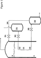
図1に示すように、LTFTスラリバブル塔反応器1の上方セクション内で、スラリレベル2の下には、本発明によるスラリから液体を分離する装置が配置されている。この分離装置は、スラリ中で垂直方向に浸漬される複数の中空フィルタエレメントを有している。簡単化のため、図1には、このようなフィルタエレメント11のうちの1つのみが示されている。フィルタエレメント11は、表面フィルタ、好ましくは、両端が閉じられたステンレス鋼織成ワイヤフィルタまたはスロットフィルタである。フィルタエレメントのメッシュサイズは、スラリ中の触媒粒子の平均粒子サイズと同程度であるのが好ましい。フィルタエレメント11の上部のフィルタエレメント入口導管12は、フィルタエレメント11と、すすぎ流体およびバックフラッシング流体を供給する容器21とを連結し、フィルタエレメント11の底に配置されたフィルタエレメント出口導管13は、フィルタエレメント11と、濾液およびすすぎ流体を貯蔵する容器22とを連結している。上記特許文献3において更に詳細に説明されているように、貯蔵容器22の上部とLTFTスラリバブル塔反応器1内のスラリレベル2の上方の気相との間を連結するガス連通導管14は、貯蔵容器22とLTFTスラリバブル塔反応器1との間のガス連通を確保する。
Hereinafter, the present invention will be described in detail with reference to the accompanying drawings.
As shown in FIG. 1, in the upper section of the LTFT slurry
上記3つの各導管12、13、14には、流体がこれらの導管を通ることを防止しまたは許容するための弁、すなわちガス連通導管弁31と、フィルタエレメント入口導管弁32と、フィルタエレメント出口導管弁33とが設けられている。
第一実施形態では、LTFT3相スラリバブル塔反応器1から液体を分離する方法は、中空フィルタエレメント11と、該フィルタエレメント上に蓄積した任意のフィルタケーキとの間に小さい圧力差を付与して、フィルタエレメントの内側から濾液を得てかつ吸引する段階を有している。この圧力差は、LTFT3相スラリバブル塔反応器1内のスラリレベル2により、および貯蔵容器22の上部とLTFTスラリバブル塔反応器1内のスラリレベル2の上方の気相との間のガス連通導管14のガス連通導管弁31を開いた状態に維持することにより制御される。濾液は、フィルタエレメント出口導管弁33を開くことにより、フィルタエレメント11からフィルタエレメント出口導管13を通って、濾液貯蔵容器22へと吸引される。
Each of the three
In the first embodiment, the method of separating liquid from the LTFT three-phase slurry
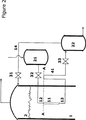
任意であるが、フィルタエレメント出口導管13には、図2に示すいわゆる「グースネック」(ガチョウ頚部形部)41を設けることができる。「グースネック」41は、フィルタエレメント導管13の曲り部である。曲り部の垂直レベルは、図2に垂直レベル線A−Aで示すように、フィルタエレメント11の頂部と同じ垂直レベルを有している。この任意の「グースネック」41は、濾過段階中に、フィルタエレメント11の内部が液体で充満されることを確保する。
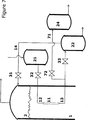
また、任意であるが、フィルタエレメント出口導管13には、図3に示すように、フィルタエレメント出口導管流れ制御弁34を設けることができる。これにより、望むならば、濾過段階中に濾液流量を制御しかつフィルタエレメント11の内部を液体で充満された状態に維持できる。
Optionally, the filter
Also, optionally, the filter
再び図1を参照すると、フィルタエレメント入口導管弁32を開くことにより、濾過段階に続き、すすぎ段階が行われる。次に、フィルタエレメント11の内部が、フィルタエレメント入口導管12を通して、すすぎ流体供給容器21からの凝縮されたガス状LTFT生成物からなるすすぎ流体により充填される。スラリ相では、フィルタエレメントを通ってスラリ相内に流入するすすぎ流体の移動を最小にするため、すすぎ流体の充填圧力は、フィルタエレメント11の外部の圧力と同じかこれより低くすべきである(いずれの図面にも含まれていないが、すすぎ流体供給容器21の圧力制御手段が必要であることは、当業者には明白であろう)。すすぎ流体の体積は、フィルタエレメント11の内容積と同じであるか、これより大きくなるように選択すべきである。すすぎ流体およびフィルタエレメント11の内部に集積されたあらゆる微細粒子は、次に、フィルタエレメント11からフィルタエレメント出口導管13を通って貯蔵容器22内に取出される。
Referring again to FIG. 1, the rinsing stage is performed following the filtration stage by opening the filter element
すすぎ流体の充填圧力、およびフィルタエレメント11および該フィルタエレメントの外面上のフィルタケーキを横切る圧力降下によっては、すすぎ段階中に、スラリ相からフィルタエレメントを横切る濾液の移動が生じることも、生じないこともある。
ガス連通導管弁31およびフィルタエレメント出口導管弁33を閉じることにより、すすぎ段階に続いてバックフラッシング段階が行われる。
この第一実施形態では、バックフラッシング流体およびすすぎ流体は同じ流体であり、供給容器21からフィルタエレメント入口導管12を通って供給される凝縮されたガス状LTFT生成物である。
Depending on the filling pressure of the rinsing fluid and the pressure drop across the
By closing the gas
In this first embodiment, the backflushing fluid and the rinsing fluid are the same fluid , the condensed gaseous LTFT product supplied from the
スラリ相では、蓄積したフィルタケーキをフィルタエレメント11から除去すべく、バックフラッシング流体をフィルタエレメントを通過して強制移動させるため、バックフラッシング流体の充填圧力は、フィルタエレメント11の外部の圧力より高くすべきである。バックフラッシング液のフラックスは、平均液体濾過フラックスの2倍に等しいか、これより大きくすべきである。
In the slurry phase, in order to remove the accumulated filter cake from the
バックフラッシング段階の完了後、フィルタエレメント入口導管弁32を閉じ、ガス連通導管弁31およびフィルタエレメント出口導管弁33を開くことにより、任意の待機時間をおいて、または待機時間をおくことなく、通常の濾過を再開できる。
任意であるが、図4に示すように、フィルタエレメント入口導管12には2つの弁を設けることができる。一方の弁はすすぎ流体を充填するときに開かれ、他方の弁はバックフラッシング液を充填するときに開かれる。すすぎ段階の開始時に、フィルタエレメント入口導管弁32は閉じた状態に維持され、一方、すすぎ流体充填制御弁35は開かれた状態に維持され、これにより、すすぎ流体の流量を制御できる。濾過段階の終時に、このすすぎ流体充填制御弁35が閉じられ、かつフィルタエレメント入口導管弁32が開かれて、この後に上記バックフラッシング段階が続けられる。
After completion of the backflushing phase, the filter element
Optionally, as shown in FIG. 4, the filter
第二実施形態では、すすぎ段階の後にバックフラッシング段階は続けられず、第二濾過段階が続けられる。これは、すすぎ段階の完了後にフィルタエレメント入口導管弁32を閉じることにより行われ、いかなる待機時間をもおくことなく新しい濾過段階を再開できる。次に、第一実施形態のすすぎ段階で説明したように、フィルタエレメント入口導管弁32を開くことにより、第二濾過段階の後に第二すすぎ段階が続けられる。第一実施形態において説明したように、第二すすぎ段階の後に、ガス連通導管弁31およびフィルタエレメント出口導管弁33を閉じることによりバックフラッシング段階を続けるか、第二すすぎ段階の後で、バックフラッシング段階の前に、1つ以上の付加濾過段階およびすすぎ段階を続けることができる。各すすぎ段階でのすすぎ流体の体積は、フィルタエレメント11の内容積に等しいか、これより大きくなるように選択すべきである。
In the second embodiment, the backflushing stage is not continued after the rinsing stage, but the second filtration stage is continued. This is done by closing the filter element
図5に示す第三実施形態では、バックフラッシング段階がガスアシストされ、フィルタエレメント入口導管12に、ガスバックフラッシング導管51が連結される。
ガスバックフラッシング導管51には、該導管51を通って液体が流れることを防止しまたは許容する弁ガスバックフラッシング導管弁52が設けられている。この実施形態でも、濾過段階およびすすぎ段階は、第一実施形態と同様に行われる。濾過段階およびすすぎ段階中、ガスバックフラッシング導管弁52は閉じられた状態に維持される。
ガスバックフラッシング段階では、ガス連通導管弁31、フィルタエレメント入口導管弁32およびフィルタエレメント出口導管弁33が閉じられ、ガスバックフラッシング導管弁52が開かれる。
In the third embodiment shown in FIG. 5, the backflushing stage is gas assisted and a
The gas back flushing
In the gas back flushing stage, the gas
ガスバックフラッシング導管51内のバックフラッシングガスとして、フィッシャー・トロプシュ反応からのガス状生成物、合成ガスまたは窒素のような不活性ガスがある。
スラリ相では、フィルタエレメント11およびフィルタエレメント入口導管12内の残留すすぎ流体を、フィルタエレメント11を通過して移動させ、蓄積したフィルタケーキを除去するため、バックフラッシングガスの圧力はフィルタエレメント11外部の圧力より高くすべきである。バックフラッシング液のフラックスは、平均液体濾過フラックスの2倍に等しいか、これより高くすべきである。
バックフラッシング段階の完了後、ガスバックフラッシング導管弁52が閉じられ、ガス連通導管弁31およびフィルタエレメント出口導管弁33が開かれて、通常の濾過が再開される。
The backflushing gas in the
In the slurry phase, the residual rinse fluid in the
After completion of the backflushing phase, the gas
図6に示す第四実施形態では、すすぎ流体およびバックフラッシング流体を供給する別々の容器が使用される。容器21はすすぎ流体のみを供給するのに使用され、一方、バックフラッシング液供給容器23は、フィルタエレメント入口導管弁32とフィルタエレメント11との間で、バックフラッシング液導管61によりフィルタエレメント入口導管12に連結されている。バックフラッシング液導管61には、該導管61を通る流体の流れを防止しまたは許容するバックフラッシング液導管弁62が設けられている。濾過段階およびすすぎ段階は、第一実施形態と同様に遂行される。すすぎ流体として、濾過された液体LTFTワックスまたは他の炭化水素液を使用できる。濾過段階およびすすぎ段階中、バックフラッシング液導管弁62は閉じられた状態に維持される。
In a fourth embodiment shown in FIG. 6, separate containers are used that supply a rinsing fluid and a backflushing fluid. The
スラリ相では、バックフラッシング段階において、ガス連通導管弁31、フィルタエレメント入口導管弁32およびフィルタエレメント出口導管弁33が閉じられ、バックフラッシング導管弁62が開かれ、フィルタエレメント11の外部の圧力より高いバックフラッシング圧力を加えて、バックフラッシング流体をフィルタエレメント11を通過して強制的に移動させ、蓄積したフィルタケーキを除去する。バックフラッシング液のフラックスは、平均液体濾過フラックスの2倍に等しいか、これより大きくすべきである。バックフラッシング流体として、供給容器23からバックフラッシング液導管61を通って供給される凝縮ガス状LTFT生成物または他の炭化水素液を使用できる。
バックフラッシング段階の完了後、バックフラッシング液導管弁62が閉じられ、かつガス連通導管弁31およびフィルタエレメント出口導管弁33が開かれて、通常の濾過が再開される。
In the slurry phase, in the back flushing stage, the gas
After completion of the backflushing phase, the backflushing
図7に示す第五実施形態では、濾液およびすすぎ流体を貯蔵する別々の容器が使用される。容器22は濾液のみを貯蔵するのに使用され、一方、すすぎ流体貯蔵容器24は、フィルタエレメント出口導管弁33とフィルタエレメント11との間で、すすぎ流体導管71によりフィルタエレメント出口導管13に連結されている。すすぎ流体導管71には、該導管71を通る流体の流れを防止しまたは許容するすすぎ流体導管弁72が設けられている。濾過段階およびすすぎ段階は、第一実施形態と同様に遂行される。この実施形態では、濾過段階は、すすぎ流体導管弁72を閉じた状態にして第一実施形態と同様に遂行される。
この濾過段階の後、フィルタエレメント出口導管弁33を閉じ、かつフィルタエレメント入口導管弁32およびすすぎ流体導管弁72を開くことによりすすぎ段階が続けられる。次に、フィルタエレメント11の内部が、すすぎ流体供給容器21からフィルタエレメント入口導管12を通して、凝縮ガス状LTFT生成物からなるすすぎ流体で充填される。
In the fifth embodiment shown in FIG. 7, separate containers for storing filtrate and rinsing fluid are used.
After this filtration step, the rinsing step is continued by closing the filter element
スラリ相では、フィルタエレメントを通る、スラリ相中へのすすぎ流体の移動を最小にすべく、すすぎ流体の充填圧力は、フィルタエレメント11の外部の圧力に等しいか、これより低くすべきである。すすぎ流体の体積は、フィルタエレメント11の内容積に等しいか、これより大きくなるように選択すべきである。次に、すすぎ流体およびフィルタエレメント11内に集積された全ての微細粒子が、フィルタエレメント11からすすぎ流体導管71弁を通ってすすぎ流体貯蔵容器24に取出される。
In the slurry phase, the rinse fluid fill pressure should be equal to or less than the pressure outside the
スラリ相では、バックフラッシング流体を、フィルタエレメント11を通過して強制的に移動させ、フィルタケーキを除去すべく、すすぎ段階の後に、ガス連通導管弁31およびすすぎ流体導管弁72を閉じ、かつフィルタエレメント11の外部の圧力より高いバックフラッシング圧力を加えることによりバックフラッシング段階が続けられる。この実施形態では、バックフラッシング流体およびすすぎ流体は同じ流体、すなわち供給容器21からフィルタエレメント入口導管12を通して供給される凝縮LTFT生成物である。バックフラッシング液のフラックスは、平均液体濾過フラックスの2倍に等しいか、これより大きくすべきである。
In the slurry phase, the backflushing fluid is forced through the
バックフラッシング段階の完了後、フィルタエレメント入口導管弁32が閉じられ、かつガス連通導管弁31およびフィルタエレメント出口導管弁33が開かれて、通常の濾過が再開される。
図8に示す第六実施形態では、すすぎ流体およびバックフラッシング液を供給し、および濾液およびすすぎ流体を貯蔵する別々の容器は存在しない。すすぎ流体およびバックフラッシング液の両方に、濾過された液体LTFT生成ワックスが使用され、容器22は、すすぎ流体およびバックフラッシング液の供給および濾液の貯蔵の両方の機能を有している。濾液貯蔵出口81から、濾液の一部を、液体再循環ポンプ83を通して液体再循環導管82のフィルタエレメント11に再循環させることができる。
液体再循環導管82には、弁すなわち、流体の流れを防止しまたは許容する液体再循環導管弁84、すすぎ流体制御弁85およびバックフラッシング弁86が設けられている。
After completion of the backflushing phase, filter element
In the sixth embodiment shown in FIG. 8, there are no separate containers for supplying rinsing fluid and backflushing liquid and for storing filtrate and rinsing fluid . Filtered liquid LTFT-producing wax is used for both the rinsing fluid and the backflushing liquid, and the
The
この実施形態は、フィルタエレメントの内部から濾液を得てかつ吸引すべく、中空フィルタエレメント11と該フィルタエレメント上に蓄積された全てのフィルタケーキとの間に小さい圧力差を生じさせる段階を有している。この圧力差は、LTFT3相スラリバブル塔反応器1内のスラリレベル2により、および貯蔵容器22の上部とLTFTスラリバブル塔反応器1内のスラリレベル2より上方の気相との間の導管14のガス連通導管弁31を開いた状態に維持することにより制御される。濾液は、フィルタエレメント出口導管弁33を開き、フィルタエレメント11から、フィルタエレメント11からフィルタエレメント出口導管13を通して濾液貯蔵容器22に吸引される。フィルタエレメント出口導管13には、濾液流量を制御するためのフィルタエレメント出口導管流れ制御弁34が設けられている。濾過段階中は、液体再循環導管弁84が閉じられた状態に維持される。
This embodiment comprises the step of creating a small pressure difference between the
次に、液体再循環弁84およびすすぎ流体制御弁85を開き、フィルタエレメント11の内部に、容器22から液体再循環導管82および液体再循環ポンプ83を通して、すすぎ流体としての濾過されたLTFT生成ワックスが充填される。すすぎ段階中は、バックフラッシング弁86が閉じられた状態に維持される。
スラリ相では、濾過された液体LTFT生成ワックスの、フィルタエレメントを横切るスラリ相中への移動を最小にするため、濾過された液体LTFT生成ワックスの充填圧力は、フィルタエレメント11の外部の圧力に等しいか、これより低くすべきである。すすぎ段階における濾過された液体LTFT生成ワックスは、フィルタエレメント11の内容積に等しいか、これより大きくなるように選択すべきである。次に、濾過された液体LTFT生成ワックスおよびフィルタエレメント11内に集積されたあらゆる微細粒子が、フィルタエレメント11からすすぎ流体導管33を通ってすすぎ流体貯蔵容器22に取出される。
Next, the
In the slurry phase, the filling pressure of the filtered liquid LTFT generation wax is equal to the pressure outside the
スラリ相では、濾過された液体LTFT生成ワックスを、フィルタエレメント11を通過して強制的に移動させ、蓄積したフィルタケーキを除去すべく、すすぎ段階の後に、ガス連通導管弁31、フィルタエレメント出口導管弁33およびバックフラッシング弁86を閉じ、かつフィルタエレメント11の外部の圧力より高いバックフラッシング圧力を加えることによりバックフラッシング段階が続けられる。
バックフラッシング段階の完了後、液体再循環導管弁84およびバックフラッシング弁86が閉じられ、かつガス連通導管弁31およびフィルタエレメント出口導管弁33が開かれて、通常の濾過が再開される。
In the slurry phase, the filtered liquid LTFT generated wax is forced through the
After completion of the backflushing phase, liquid
任意であるが、バックフラッシング液として使用される再循環液は、図9に示すように、再循環ポンプ83を通さないルートにすることもできる。
任意であるが、再循環された液体は、図10に示すように、再循環液貯蔵タンク内容積に貯蔵することもできる。液体再循環導管82を通って再循環される液体は、再循環された液体が前述のようにすすぎ段階およびバックフラッシング段階で使用される前に、液体再循環ポンプ83を通って液体再循環貯蔵タンク24へとポンピングされる。
Although optional, the recirculation fluid used as the backflushing fluid can be routed through the
Optionally, the recirculated liquid can also be stored in the recirculated liquid storage tank internal volume, as shown in FIG. The liquid recirculated through the
図8を参照して説明した第六実施形態では、濾過段階およびすすぎ段階が並列的に運転される。濾過段階中は、液体再循環弁84およびすすぎ流体制御弁85は開いた状態に維持され、フィルタエレメント11の内部を、スラリ相からフィルタエレメント11を通過して移動される濾液に加え、容器22から液体再循環導管82および液体再循環ポンプ83を通って供給される濾過された液体LTFT生成ワックスで充填する。
In the sixth embodiment described with reference to FIG. 8, the filtration stage and the rinsing stage are operated in parallel. During the filtration step, the
スラリ相では、すすぎ流体の、フィルタエレメントを横切るスラリ相中への移動を防止すべく、濾過された液体LTFT生成ワックスの充填圧力は、フィルタエレメント11の外部の圧力より低くすべきである。スラリ相では、濾過された液体LTFT生成ワックスを、フィルタエレメント11を通過して強制的に移動させ、蓄積したフィルタケーキを除去すべく、組合わされた濾過/すすぎ段階の後に、ガス連通導管弁31、フィルタエレメント出口導管弁33を閉じ、バックフラッシング弁86を開き、かつフィルタエレメント11の外部の圧力より高いバックフラッシング圧力を加えることにより、バックフラッシング段階が続けられる。
バックフラッシング段階の完了後、バックフラッシング弁86が閉じられかつガス連通導管弁31およびフィルタエレメント出口導管弁33が開かれて、組合わされた濾過/すすぎを再開できる。
In the slurry phase, the fill pressure of the filtered liquid LTFT-producing wax should be lower than the pressure external to the
After completion of the backflushing phase,
当業者ならば、本発明の範囲内で、上記異なる実施形態の種々の組合せが可能であることが理解されよう。
また、上記説明並びに下記例は、当業者による本発明の理解を補助するためのものであり、本発明の合理的範囲を不当に制限するものであると解釈すべきではない。
Those skilled in the art will appreciate that various combinations of the above different embodiments are possible within the scope of the present invention.
Further, the above description and the following examples are intended to assist those skilled in the art in understanding the present invention, and should not be construed to unduly limit the reasonable scope of the present invention.
本発明を以下の例により更に説明する。
例1
この第一例では、図5に示した一実施形態に設けられた2.7mの内径および28mの高さを有するLTFT3相スラリ反応器および本発明による濾過方法を使用した。この装置は、スラリ中に垂直方向に浸漬される、両端部が閉じられた複数の中空フィルタエレメントを有している。フィルタエレメントは、フィルタエレメント群をなして配置された。
フィルタエレメントの濾材は、70μmの平均孔サイズをもつステンレス鋼織成ワイヤメッシュから製造された。この実験でのスラリ中の触媒粒子の濃度は8重量%であり、下記の粒子サイズ分布を有するものであった。
<100μm95体積%
<70μm50体積%
<25μm10体積%
<5μm3体積%
LTFTスラリ反応器の圧力は1600kPaであった。濾過段階中、フィルタエレメントの内部から濾液を得てこれを吸引するため、フィルタエレメントと該フィルタエレメントの外面に蓄積されたフィルタケーキとを横切る0.01〜100kPaの濾過圧力差を発生させた。1群のフィルタエレメントについては、この群のフィルタエレメントの内部を、濃縮LTFT生成物からなるすすぎ流体で充填することにより、濾過段階の後にすすぎ段階が続けられた。すすぎ流体流量は、LTFT反応器と、すすぎ流体およびバックフラッシング液を供給する容器との間の差圧により制御された。
The invention is further illustrated by the following examples.
Example 1
In this first example, an LTFT three-phase slurry reactor having an inner diameter of 2.7 m and a height of 28 m provided in one embodiment shown in FIG. 5 and the filtration method according to the present invention were used. The device has a plurality of hollow filter elements closed at both ends that are immersed vertically in the slurry. The filter elements were arranged as a group of filter elements.
The filter element filter media was manufactured from a stainless steel woven wire mesh having an average pore size of 70 μm. The concentration of the catalyst particles in the slurry in this experiment was 8% by weight, and had the following particle size distribution.
<100 μm 95% by volume
<70 μm 50% by volume
<25 μm 10% by volume
<5μm3vol%
The pressure in the LTFT slurry reactor was 1600 kPa . During the filtration step, a filtration pressure difference of 0.01 to 100 kPa was generated across the filter element and the filter cake accumulated on the outer surface of the filter element in order to obtain filtrate from the inside of the filter element and suck it. For a group of filter elements, the rinsing step was followed by a filtration step by filling the interior of this group of filter elements with a rinsing fluid comprising the concentrated LTFT product. The rinse fluid flow rate was controlled by the differential pressure between the LTFT reactor and the vessel supplying the rinse fluid and backflushing liquid.
濃縮LTFT生成物からなるバックフラッシング液を、濾材を通過して逆方向に強制的に押出してフィルタケーキを除去するため、LTFT反応器と、すすぎ流体およびバックフラッシング液を供給する容器との間に500kPaのバックフラッシング圧力差を発生させることにより、このすすぎ段階の後にバックフラッシング段階が続けられた。バックフラッシング液は、1〜5秒間フィルタエレメント内に流入することが許容された。その後、0.5〜10秒間フィルタエレメントを通る付加バックフラッシュパルスとして、不活性ガスの流れが使用された。バックフラッシング段階の後、新しい濾過段階が開始された。各群のフィルタエレメントについて、上記手順が反復された。 Between the LTFT reactor and the vessel supplying the rinsing fluid and backflushing liquid, the backflushing liquid comprising the concentrated LTFT product is forced through the filter medium in the reverse direction to remove the filter cake. This rinsing step was followed by a backflushing step by generating a 500 kPa backflushing pressure differential. The backflushing liquid was allowed to flow into the filter element for 1-5 seconds. The inert gas flow was then used as an additional backflush pulse through the filter element for 0.5-10 seconds. After the backflushing phase, a new filtration phase was started. The above procedure was repeated for each group of filter elements.
例2
この例では、図9に示した一実施形態に設けられた55mmの内径および5mの高さを有するLTFT3相スラリ反応器および本発明による濾過方法を使用した。この装置は、スラリ中に垂直方向に浸漬される、両端部が閉じられた単一の中空フィルタエレメントを有している。フィルタエレメントの濾材は、70μmの平均孔サイズをもつステンレス鋼織成ワイヤメッシュから製造された。この実験でのスラリ中の触媒粒子の濃度は12重量%であり、下記の粒子サイズ分布を有するものであった。
<100μm95体積%
<70μm50体積%
<25μm10体積%
<5μm3体積%
LTFTスラリ反応器の圧力は2000kPaであった。濾過段階中、フィルタエレメントの内部から濾液を得てこれを吸引するため、フィルタエレメントと該フィルタエレメントの外面に蓄積されたフィルタケーキとを横切る0.01〜30kPaの濾過圧力差を発生させた。フィルタエレメントの内部を、再循環された濾過液体LTFTワックスからなるすすぎ流体で充填することにより、濾過段階の後にすすぎ段階が続けられた。再循環された濾過液体LTFTワックスは、再循環の前に貯蔵容器内でガス抜きされた。すすぎ流体流量は、フィルタエレメントの前の導管に設けられた制御弁により制御された。使用した流量は、濾過速度の10〜50%の範囲内で、5〜60秒間使用された。
Example 2
In this example, an LTFT three-phase slurry reactor with an inner diameter of 55 mm and a height of 5 m provided in one embodiment shown in FIG. 9 and the filtration method according to the present invention were used. The device has a single hollow filter element closed at both ends that is vertically immersed in the slurry. The filter element filter media was manufactured from a stainless steel woven wire mesh having an average pore size of 70 μm. The concentration of the catalyst particles in the slurry in this experiment was 12% by weight, and had the following particle size distribution.
<100 μm 95% by volume
<70 μm 50% by volume
<25 μm 10% by volume
<5μm3vol%
The pressure in the LTFT slurry reactor was 2000 kPa . During the filtration stage, a filtration pressure difference of 0.01 to 30 kPa was generated across the filter element and the filter cake accumulated on the outer surface of the filter element in order to obtain and suck the filtrate from the inside of the filter element. The rinsing step was followed by a filtration step by filling the interior of the filter element with a rinsing fluid consisting of recycled filtered liquid LTFT wax. The recirculated filtered liquid LTFT wax was degassed in the storage container prior to recirculation. The rinse fluid flow rate was controlled by a control valve provided in the conduit in front of the filter element. The flow rate used was in the range of 10-50% of the filtration rate and was used for 5-60 seconds.
再循環された濾過液体LTFTワックスを、濾材を通過して逆方向に強制的にバックフラッシングしてフィルタケーキを除去するため、LTFT反応器と、貯蔵容器との間に80kPaのバックフラッシング圧力差を発生させかつ貯蔵容器を加圧することにより、このすすぎ段階の後にバックフラッシング段階が続けられた。バックフラッシング流量は濾過流量の少なくとも2倍、一般に約10.000〜20.0000kg/m2hであった。
バックフラッシング液は、3〜20秒間フィルタエレメント内に流入することが許容された。その後、貯蔵容器およびLTFT反応器内の圧力が均衡化され、新しい濾過段階が開始された。
In order to remove the filter cake by forcibly backflushing the recirculated filtered liquid LTFT wax through the filter media in the reverse direction, a backflushing pressure difference of 80 kPa is applied between the LTFT reactor and the storage vessel. This rinsing step was followed by a backflushing step by generating and pressurizing the storage container. The backflushing flow rate was at least twice the filtration flow rate, generally about 10.000-20.000 kg / m 2 h.
The backflushing liquid was allowed to flow into the filter element for 3-20 seconds. Thereafter, the pressure in the storage vessel and LTFT reactor was balanced and a new filtration stage was started.
図11には、この実験での20サイクルの濾過、すすぎおよびバックフラッシングからのフラックス量(kg/m2h)が示されている。図11には2つの曲線が示されており、1つの曲線は真正フラックスを示し、他の曲線は、30分間の平均フラックスを示す。
真正フラックスを示す曲線は、各サイクル内の真正フラックスがバックフラッシング段階の直後に非常に高いこと、および真正フラックスが濾過シーケンスの間中徐々に低減することを示している。30分間の平均フラックスを示す曲線は、各濾過シーケンス内の平均フラックスが一定であり、経時による濾過能力の顕著な損失が見られないことを示している。
FIG. 11 shows the flux (kg / m 2 h) from 20 cycles of filtration, rinsing and backflushing in this experiment. FIG. 11 shows two curves, one curve showing authentic flux and the other curve showing 30 minute average flux.
The curve showing authentic flux shows that the authentic flux within each cycle is very high immediately after the backflushing phase and that the authentic flux gradually decreases during the filtration sequence. The curve showing the average flux for 30 minutes shows that the average flux within each filtration sequence is constant and there is no significant loss of filtration capacity over time.
1 LTFTスラリバブル塔反応器
11 フィルタエレメント
21 すすぎ流体およびバックフラッシング流体の供給容器
22 濾液およびすすぎ流体の貯蔵容器
23 バックフラッシング液供給容器
24 すすぎ流体貯蔵タンク
35 すすぎ流体充填制御弁
41 グースネック
51 ガスバックフラッシング導管
61 バックフラッシング液導管
71 すすぎ流体導管
83 液体再循環ポンプ
DESCRIPTION OF
Claims (19)
b)フィルタの内部から触媒微細片を洗浄すべく、前記段階と並列的にまたは前記段階に続いて、フィルタエレメントの内部にすすぎ流体を充填する段階と、
c)バックフラッシング流体を、濾材を通過して逆方向に押出して蓄積したフィルタケーキを除去すべく、前記濾過圧力差とは逆の逆洗圧力差を発生させる段階とを有することを特徴とする3相スラリバブル塔反応器から液体を分離する方法。a) generating a filtration pressure difference through the filter element of the hollow filter element and all the filter cake accumulated on the outer surface of the filter element to obtain filtrate from the filter element and suck it;
b) filling the interior of the filter element with a rinsing fluid in parallel with or subsequent to the step to wash the catalyst fines from the interior of the filter;
and c) generating a backwash pressure difference opposite to the filtration pressure difference in order to remove the accumulated filter cake by extruding the back flushing fluid through the filter medium in the reverse direction. A method of separating liquid from a three-phase slurry bubble column reactor.
b)フィルタの内容積に連通している1つ以上の導管とを有し、少なくとも1つの導管はすすぎ流体の流入を行うように構成されまたは連結されており、少なくとも1つの導管はすすぎ流体の流出を行うように構成されまたは連結されていることを特徴とする3相スラリバブル塔反応器から液体を分離する装置。a) at least one hollow-enclosed filter element;
b) one or more conduits in communication with the internal volume of the filter, wherein at least one conduit is configured or connected for inflow of a rinsing fluid and at least one conduit of the rinsing fluid An apparatus for separating a liquid from a three-phase slurry bubble column reactor, characterized in that it is configured or connected for effluent.
Applications Claiming Priority (7)
| Application Number | Priority Date | Filing Date | Title |
|---|---|---|---|
| ZA2005/8009 | 2005-10-04 | ||
| ZA200508009 | 2005-10-04 | ||
| US74062405P | 2005-11-28 | 2005-11-28 | |
| US60/740,624 | 2005-11-28 | ||
| ZA200510404 | 2005-12-22 | ||
| ZA2005/10404 | 2005-12-22 | ||
| PCT/ZA2006/000113 WO2007041726A1 (en) | 2005-10-04 | 2006-10-02 | Filtration method and installation |
Publications (2)
| Publication Number | Publication Date |
|---|---|
| JP2009509765A JP2009509765A (en) | 2009-03-12 |
| JP4903802B2 true JP4903802B2 (en) | 2012-03-28 |
Family
ID=37622220
Family Applications (1)
| Application Number | Title | Priority Date | Filing Date |
|---|---|---|---|
| JP2008534798A Expired - Fee Related JP4903802B2 (en) | 2005-10-04 | 2006-10-02 | Filtration method and filtration device |
Country Status (10)
| Country | Link |
|---|---|
| US (1) | US8778193B2 (en) |
| EP (1) | EP1940540B1 (en) |
| JP (1) | JP4903802B2 (en) |
| CN (1) | CN101356000B (en) |
| AP (1) | AP2467A (en) |
| AT (1) | ATE442898T1 (en) |
| CA (1) | CA2624815C (en) |
| DE (1) | DE602006009288D1 (en) |
| ES (1) | ES2333473T3 (en) |
| WO (1) | WO2007041726A1 (en) |
Families Citing this family (16)
| Publication number | Priority date | Publication date | Assignee | Title |
|---|---|---|---|---|
| JP5259623B2 (en) * | 2007-01-11 | 2013-08-07 | ザ ペトロリウム オイル アンド ガス コーポレイション オブ サウス アフリカ (プロプライエタリー) リミテッド | Method and system for protecting the internal filter of an LTFT slurry bubble column reactor |
| WO2009027914A2 (en) * | 2007-08-24 | 2009-03-05 | Sasol Technology (Proprietary) Limited | Process for producing liquid and gaseous products from gaseous reactants |
| GB2465554B (en) | 2008-11-18 | 2013-03-13 | Gtl F1 Ag | Slurry bubble column reactor |
| US9238586B2 (en) * | 2008-11-20 | 2016-01-19 | Alion Science & Technology | Filter cleaning method |
| GB2466315B (en) * | 2008-12-22 | 2013-01-09 | Gtl F1 Ag | Apparatus and method for conducting a Fischer-Tropsch synthesis reaction |
| BRPI1009483B1 (en) * | 2009-03-19 | 2018-05-15 | Japan Oil, Gas And Metals National Corporation | CATALYST SEPARATION SYSTEM |
| GB2471338B (en) | 2009-06-26 | 2014-12-24 | Gtl F1 Ag | Apparatus and process for three-phase reacton |
| JP5889539B2 (en) * | 2011-03-28 | 2016-03-22 | 独立行政法人石油天然ガス・金属鉱物資源機構 | Process for producing hydrocarbons |
| JP6173307B2 (en) * | 2011-06-24 | 2017-08-02 | アンガス ケミカル カンパニー | Method and apparatus for the production and filtration of amino alcohols using a continuous stirred tank slurry reactor |
| JP5846799B2 (en) * | 2011-08-05 | 2016-01-20 | 独立行政法人石油天然ガス・金属鉱物資源機構 | Filter cleaning equipment |
| UA113744C2 (en) | 2011-12-08 | 2017-03-10 | DEVICE FOR FORMATION OF AEROSOL WITH INTERNAL HEATER | |
| EP3247776B1 (en) * | 2015-01-20 | 2019-11-13 | The Petroleum Oil and Gas Corporation of South Africa (Pty) Ltd. | Ltft catalyst fines removal |
| US10058803B2 (en) | 2015-12-18 | 2018-08-28 | Synfuel Americas Corporation | Filter assembly and method of use |
| JP2019523702A (en) | 2016-06-02 | 2019-08-29 | レール・リキード−ソシエテ・アノニム・プール・レテュード・エ・レクスプロワタシオン・デ・プロセデ・ジョルジュ・クロード | Slurry bubble column reactor for Fischer-Tropsch process |
| CN109382043A (en) * | 2017-08-07 | 2019-02-26 | 神华集团有限责任公司 | The in situ regeneration method of Fischer-Tropsch synthesis device filter element and the F- T synthesis system of application in situ regeneration method |
| CN108178130A (en) * | 2018-01-23 | 2018-06-19 | 北京澳柯清洁煤气工程技术有限公司 | A kind of continuous sulfur melting system and method |
Family Cites Families (12)
| Publication number | Priority date | Publication date | Assignee | Title |
|---|---|---|---|---|
| US4605678A (en) * | 1984-03-12 | 1986-08-12 | Mobil Oil Corporation | Separation of catalyst from slurry bubble column wax and catalyst recycle |
| GB9203958D0 (en) | 1992-02-25 | 1992-04-08 | Norske Stats Oljeselskap | Catalytic multi-phase reactor |
| US5599849A (en) * | 1993-01-27 | 1997-02-04 | Sasol Chemical Industries (Proprietary) Limited | Process for producing liquid and, optionally, gaseous products from gaseous reactants |
| US5468397A (en) * | 1993-03-16 | 1995-11-21 | Memtec America Corporation | Gas backwash of pleated filters |
| EG22489A (en) | 1999-02-05 | 2003-02-26 | Sasol Technology | Process for producing liquid and optionally gaseous products from gaseous reactants |
| JP2001321611A (en) * | 2000-05-18 | 2001-11-20 | Ishigaki Co Ltd | Filter device |
| EP1174177A3 (en) * | 2000-07-18 | 2002-12-04 | Nitto Denko Corporation | Spiral wound membrane element, spiral wound membrane module and treatment system employing the same as well as running method and washing method therefor |
| US6652760B2 (en) * | 2001-03-12 | 2003-11-25 | Texaco Inc. | Internal filter for fischer-tropsch catalyst/wax separation |
| EP1463578B1 (en) * | 2002-01-09 | 2011-09-28 | Hydranautics | Method for cleaning a filtration membrane module with hollow fiber membranes |
| CA2482057A1 (en) * | 2002-04-16 | 2003-10-30 | Conocophillips Company | Solid/liquid separation system for multiphase converters |
| JP5155561B2 (en) * | 2003-07-15 | 2013-03-06 | サソール テクノロジー(プロプライエタリー)リミテッド | Method for separating a catalyst from a liquid |
| JP2005152778A (en) * | 2003-11-25 | 2005-06-16 | Matsushita Electric Works Ltd | Filtration tank and method for cleaning inside of filtration tank |
-
2006
- 2006-10-02 WO PCT/ZA2006/000113 patent/WO2007041726A1/en active Application Filing
- 2006-10-02 JP JP2008534798A patent/JP4903802B2/en not_active Expired - Fee Related
- 2006-10-02 CN CN2006800430287A patent/CN101356000B/en not_active Expired - Fee Related
- 2006-10-02 AT AT06817440T patent/ATE442898T1/en not_active IP Right Cessation
- 2006-10-02 ES ES06817440T patent/ES2333473T3/en active Active
- 2006-10-02 CA CA2624815A patent/CA2624815C/en not_active Expired - Fee Related
- 2006-10-02 EP EP06817440A patent/EP1940540B1/en not_active Not-in-force
- 2006-10-02 AP AP2008004427A patent/AP2467A/en active
- 2006-10-02 DE DE602006009288T patent/DE602006009288D1/en active Active
- 2006-10-02 US US12/089,197 patent/US8778193B2/en not_active Expired - Fee Related
Also Published As
| Publication number | Publication date |
|---|---|
| DE602006009288D1 (en) | 2009-10-29 |
| JP2009509765A (en) | 2009-03-12 |
| ES2333473T3 (en) | 2010-02-22 |
| EP1940540B1 (en) | 2009-09-16 |
| US8778193B2 (en) | 2014-07-15 |
| ATE442898T1 (en) | 2009-10-15 |
| AP2008004427A0 (en) | 2008-04-30 |
| CA2624815C (en) | 2014-02-18 |
| US20090261046A1 (en) | 2009-10-22 |
| WO2007041726A8 (en) | 2008-03-06 |
| EP1940540A1 (en) | 2008-07-09 |
| WO2007041726A1 (en) | 2007-04-12 |
| CA2624815A1 (en) | 2007-04-12 |
| CN101356000A (en) | 2009-01-28 |
| AP2467A (en) | 2012-09-17 |
| CN101356000B (en) | 2012-04-25 |
Similar Documents
| Publication | Publication Date | Title |
|---|---|---|
| JP4903802B2 (en) | Filtration method and filtration device | |
| JP5155561B2 (en) | Method for separating a catalyst from a liquid | |
| JP3514503B2 (en) | Method and apparatus for producing liquid and gaseous products from gaseous reactants | |
| JP5184837B2 (en) | Fischer-Tropsch catalyst / internal filter for wax separation | |
| AU767082C (en) | Process for producing liquid and, optionally, gaseous products from gaseous reactants | |
| AU664429B2 (en) | Catalytic multi-phase reactor | |
| JP4653889B2 (en) | Desorption filter for slurry hydrocarbon synthesis process | |
| RU2466780C2 (en) | Method of synthesising hydrocarbons for obtaining liquid and gaseous products from gaseous reagents | |
| CN101715477A (en) | From the fischer-tropsch materials flow, remove fine particle | |
| CA2154184C (en) | Solid/liquid slurry treatment apparatus and catalytic multi-phase reactor | |
| JP2001526587A (en) | Slurry hydrocarbon synthesis method by external product filtration | |
| EP2376600A2 (en) | Apparatus and method for conducting a fischer-tropsch synthesis reaction | |
| JP5846799B2 (en) | Filter cleaning equipment | |
| KR820001429B1 (en) | Countercurrent liquid solid contacting apparatus | |
| JP2000061210A (en) | Pressure type upward stream filter and filtering treatment using the same |
Legal Events
| Date | Code | Title | Description |
|---|---|---|---|
| A621 | Written request for application examination |
Free format text: JAPANESE INTERMEDIATE CODE: A621 Effective date: 20090527 |
|
| A977 | Report on retrieval |
Free format text: JAPANESE INTERMEDIATE CODE: A971007 Effective date: 20101013 |
|
| A131 | Notification of reasons for refusal |
Free format text: JAPANESE INTERMEDIATE CODE: A131 Effective date: 20101206 |
|
| A521 | Request for written amendment filed |
Free format text: JAPANESE INTERMEDIATE CODE: A523 Effective date: 20110303 |
|
| TRDD | Decision of grant or rejection written | ||
| A01 | Written decision to grant a patent or to grant a registration (utility model) |
Free format text: JAPANESE INTERMEDIATE CODE: A01 Effective date: 20111219 |
|
| A01 | Written decision to grant a patent or to grant a registration (utility model) |
Free format text: JAPANESE INTERMEDIATE CODE: A01 |
|
| A61 | First payment of annual fees (during grant procedure) |
Free format text: JAPANESE INTERMEDIATE CODE: A61 Effective date: 20120105 |
|
| R150 | Certificate of patent or registration of utility model |
Ref document number: 4903802 Country of ref document: JP Free format text: JAPANESE INTERMEDIATE CODE: R150 Free format text: JAPANESE INTERMEDIATE CODE: R150 |
|
| FPAY | Renewal fee payment (event date is renewal date of database) |
Free format text: PAYMENT UNTIL: 20150113 Year of fee payment: 3 |
|
| R250 | Receipt of annual fees |
Free format text: JAPANESE INTERMEDIATE CODE: R250 |
|
| R250 | Receipt of annual fees |
Free format text: JAPANESE INTERMEDIATE CODE: R250 |
|
| R250 | Receipt of annual fees |
Free format text: JAPANESE INTERMEDIATE CODE: R250 |
|
| R250 | Receipt of annual fees |
Free format text: JAPANESE INTERMEDIATE CODE: R250 |
|
| LAPS | Cancellation because of no payment of annual fees |