JP4903608B2 - Electron beam irradiation device for open containers - Google Patents
Electron beam irradiation device for open containers Download PDFInfo
- Publication number
- JP4903608B2 JP4903608B2 JP2007074328A JP2007074328A JP4903608B2 JP 4903608 B2 JP4903608 B2 JP 4903608B2 JP 2007074328 A JP2007074328 A JP 2007074328A JP 2007074328 A JP2007074328 A JP 2007074328A JP 4903608 B2 JP4903608 B2 JP 4903608B2
- Authority
- JP
- Japan
- Prior art keywords
- electron beam
- irradiation
- container
- generating means
- open container
- Prior art date
- Legal status (The legal status is an assumption and is not a legal conclusion. Google has not performed a legal analysis and makes no representation as to the accuracy of the status listed.)
- Expired - Fee Related
Links
- 238000010894 electron beam technology Methods 0.000 title claims description 154
- 230000007246 mechanism Effects 0.000 claims description 44
- 238000012545 processing Methods 0.000 claims description 41
- 230000001678 irradiating effect Effects 0.000 claims description 5
- 230000001954 sterilising effect Effects 0.000 claims description 5
- 230000005855 radiation Effects 0.000 claims description 2
- 230000032258 transport Effects 0.000 description 37
- 238000000034 method Methods 0.000 description 10
- 238000004519 manufacturing process Methods 0.000 description 7
- 238000005192 partition Methods 0.000 description 5
- 238000004659 sterilization and disinfection Methods 0.000 description 3
- 235000013361 beverage Nutrition 0.000 description 2
- 238000001816 cooling Methods 0.000 description 2
- 230000001133 acceleration Effects 0.000 description 1
- 239000002537 cosmetic Substances 0.000 description 1
- 230000007423 decrease Effects 0.000 description 1
- 229940079593 drug Drugs 0.000 description 1
- 239000003814 drug Substances 0.000 description 1
- 235000013305 food Nutrition 0.000 description 1
- WABPQHHGFIMREM-UHFFFAOYSA-N lead(0) Chemical compound [Pb] WABPQHHGFIMREM-UHFFFAOYSA-N 0.000 description 1
- 239000000463 material Substances 0.000 description 1
- 238000012805 post-processing Methods 0.000 description 1
- 238000007781 pre-processing Methods 0.000 description 1
- 239000000126 substance Substances 0.000 description 1
- 239000010409 thin film Substances 0.000 description 1
- 239000002699 waste material Substances 0.000 description 1
Images


Landscapes
- Apparatus For Disinfection Or Sterilisation (AREA)
Description
本発明は開口容器用電子線照射装置に係り、特に電子線の照射効率を向上して開口容器の内外面を良好に殺菌できる開口容器用電子線照射装置に関する。 The present invention relates to an electron beam irradiation apparatus for an open container, and more particularly to an electron beam irradiation apparatus for an open container that can improve the efficiency of electron beam irradiation and sterilize the inner and outer surfaces of the open container.
飲料や食品や医薬品、更には化粧品の充填のために、プラスチック製の開口容器が使用される。開口容器は、内容物の充填前に、内部を滅菌処理して無菌状態にし、その後内容物を充填して密封している。開口容器の滅菌処理は、設備が大掛かりとなる薬剤を用いるものに代えて電子線を使用し、高速で搬送する開口容器の内外面を滅菌することが行われてきている。 Plastic filling containers are used for filling beverages, foods, medicines, and even cosmetics. Prior to filling the contents of the open container, the inside is sterilized to be aseptic, and then the contents are filled and sealed. In the sterilization of the open container, an electron beam is used instead of using a chemical that requires a large amount of equipment, and the inner and outer surfaces of the open container that is conveyed at high speed have been sterilized.
以下、一般的なPETボトル等のプラスチック製の開口容器で、その内外面を滅菌処理する電子線照射装置の例で説明する。開口容器は、搬送中に直立状態から横倒し状態として、電子線発生手段を設けた電子線の照射区域内を回転しながら移動させ、電子線で開口容器の内外面を滅菌処理することが提案されている(例えば特許文献1参照)。 Hereinafter, an example of an electron beam irradiation apparatus that sterilizes the inner and outer surfaces of a general plastic open container such as a PET bottle will be described. It has been proposed that the open container is moved from an upright state to a lateral state during transportation and moved while rotating in the electron beam irradiation area provided with the electron beam generating means, and the inner and outer surfaces of the open container are sterilized with the electron beam. (For example, refer to Patent Document 1).
また、電子線の照射区域に電子線発生手段を縦長状に配置し、開口容器は直立状態で照射区域内に搬送し、開口容器を自転させて移動させるときに、電子線発生手段からの電子線で、開口容器の内外面を滅菌処理することが提案されている(例えば特許文献2参照)。同様に、直立状態で照射区域内に開口容器を搬送するとき、照射区域内には一つの電子線照射手段を設け、この電子線照射手段からの電子線を、交流磁場で容器の搬送方向に沿って走査し、電子線を放射状ノズルで細分化させ、複数個の開口容器に順次電子線を照射して滅菌処理することも提案されている(特許文献3参照)。 In addition, when the electron beam generating means is arranged vertically in the electron beam irradiation area, the open container is transported into the irradiation area in an upright state, and the electron from the electron beam generating means is moved when the open container is rotated. It has been proposed to sterilize the inner and outer surfaces of the open container with a wire (see, for example, Patent Document 2). Similarly, when the open container is transported into the irradiation area in an upright state, one electron beam irradiation means is provided in the irradiation area, and the electron beam from the electron beam irradiation means is transferred in the container transport direction by an alternating magnetic field. It has also been proposed to perform sterilization by scanning along, subdividing the electron beam with a radial nozzle, and sequentially irradiating the plurality of open containers with the electron beam (see Patent Document 3).
上記特許文献1の電子線照射装置では、直立した状態で搬送している開口容器を一旦横倒し、この横倒し移送状態で照射処理を行うものであるから、生産ライン中に殺菌装置を配置するには、横倒し機構や引起し機構が必要になり、これらの機構のために、開口容器の搬送速度が著しく低下するため、高速で搬送して生産効率の向上が望まれる生産ラインに組み込みにくい問題がある。 In the electron beam irradiation apparatus of the above-mentioned Patent Document 1, the open container that is being conveyed in an upright state is temporarily laid down, and irradiation treatment is performed in the state of being laid down. In addition, a sideways mechanism and a pulling mechanism are required, and because of these mechanisms, the transport speed of the open container is remarkably reduced, and there is a problem that it is difficult to incorporate it into a production line that is desired to improve production efficiency by transporting at high speed. .
また、特許文献2の電子線照射装置では、各種製品の生産ライン中に組み込むことができる。しかし、開口容器を連続搬送中に電子線発生手段の一個所の電子線照射窓部分を通過する過程で、個々の開口容器を電子線で側面から照射して滅菌処理を施すものなので、開口容器の内外面を十分に滅菌するには、搬送速度を遅くしたりするか、高エネルギーの電子線発生手段を用いねばならない問題がある。
Moreover, the electron beam irradiation apparatus of
更に、特許文献3の電子線照射装置では、連続搬送される各開口容器の照射処理のため、一つの電子線照射手段に多数の放射状ノズルを分岐して設ける必要があって複雑な構造となるし、開口容器の内部まで十分に電子線で照射して滅菌するには、搬送速度を落とす必要があり、生産ラインの効率向上に支障をきたす問題がある。
Furthermore, in the electron beam irradiation apparatus of
これを改善するため、本発明者らは開口容器用電子線照射装置を、照射処理槽内に回転搬送体を配置して回転可能にすると共に、回転搬送体の外面に等間隔に設ける複数の保持機構で開口容器は各保持機構で保持し、順に高速で回転搬送できる構造とすることを提案している。この装置では、照射処理槽と回転搬送体との間に形成する搬送路の特定範囲を照射区域とし、照射区域の搬送路の上方に電子線発生手段を配置し、電子線発生手段からの電子線の照射で、開口容器を滅菌処理する。 In order to improve this, the present inventors have arranged an electron beam irradiation apparatus for an opening container so that it can be rotated by arranging a rotary carrier in the irradiation treatment tank, and a plurality of them are provided at equal intervals on the outer surface of the rotary carrier. It has been proposed that the opening container is held by each holding mechanism by the holding mechanism and can be rotated and conveyed at high speed in order. In this apparatus, a specific range of a transport path formed between the irradiation processing tank and the rotary transport body is set as an irradiation area, and an electron beam generating means is disposed above the transport path of the irradiation area, and an electron from the electron beam generating means is arranged. Sterilize the open container with radiation.
しかし、上記した開口容器用電子線照射装置では、照射処理槽の照射区域に回転搬送されてきた開口容器は、照射処理槽の上面の小さな照射窓部分を通過させた電子線で照射され、滅菌処理するものである。このため、電子線は、電子線発生手段における電子線発生源のグリッドの放出口と照射処理槽の照射窓、更に開口容器の位置が、同一線上とならずに少しでもずれると、開口容器への電子線の照射量は減少してしまい、極端な場合には開口容器の電子線の照射効率は半分以下になってしまう恐れがある。 However, in the above-described electron beam irradiation apparatus for an open container, the open container that has been rotated and conveyed to the irradiation area of the irradiation processing tank is irradiated with an electron beam that has passed through a small irradiation window portion on the upper surface of the irradiation processing tank, and sterilized. It is something to process. For this reason, the electron beam is transferred to the open container when the emission port of the grid of the electron beam generation source in the electron beam generating means, the irradiation window of the irradiation processing tank, and the position of the open container are not on the same line and are slightly shifted. The amount of electron beam irradiation decreases, and in an extreme case, the electron beam irradiation efficiency of the open container may become half or less.
また、この種の開口容器用電子線照射装置は、電子線発生手段から電子線は連続照射しているから、上記のようにずれてしまうと照射窓に対向する位置の開口容器だけでなく、隣接する開口容器の外面に照射され、開口容器に対する電子線の照射が過剰となってしまう恐れがある。 In addition, since this type of electron beam irradiation device for an open container continuously irradiates an electron beam from the electron beam generating means, not only the open container at the position facing the irradiation window when shifted as described above, There is a possibility that the outer surface of the adjacent open container is irradiated and the electron beam is excessively irradiated to the open container.
照射対象以外の開口容器への電子線の照射を防ぐためには、回転搬送体の保持機構の間隔を広げて開口容器を搬送するようにし、また各保持機構部分に電子線シールドを取り付け、電子線照射の範囲を制限する等の工夫が必要となる。この結果、回転搬送体及び照射処理槽の寸法が大きくなるし、また電子線発生手段の電源装置の容量も大きなものとなるから、高速で開口容器を搬送する生産ラインに適用する開口容器用電子線照射装置は、全体が大型化して経済的に製作できなる問題が生じている。 In order to prevent the irradiation of the electron beam to the opening container other than the irradiation target, the opening container is transported by increasing the interval of the holding mechanism of the rotating transport body, and an electron beam shield is attached to each holding mechanism portion, It is necessary to devise such as limiting the range of irradiation. As a result, the size of the rotary transport body and the irradiation processing tank is increased, and the capacity of the power supply device of the electron beam generating means is increased, so that the opening container electron applied to the production line that transports the open container at high speed. The beam irradiation apparatus has a problem that it becomes large in size and can be manufactured economically.
本発明の目的は、開口容器に対する電子線の照射効率を大幅に向上させ、開口容器を効果的に滅菌処理でき、小型化できて経済的に製作できる開口容器用電子線照射装置を提供することにある。 An object of the present invention is to provide an electron beam irradiation apparatus for an opening container that can significantly improve the irradiation efficiency of the electron beam to the opening container, can effectively sterilize the opening container, can be miniaturized, and can be manufactured economically. It is in.
本発明の開口容器用電子線照射装置は、照射処理槽内に回転搬送体を回転可能に配置し、前記回転搬送体の外面に等間隔に複数の保持機構を設け、前記照射処理槽と回転搬送体との間に形成する搬送路の特定範囲を電子線の照射区域とし、前記照射区域の搬送路の上方に電子線発生手段を配置し、前記回転搬送体の各保持機構により開口容器を保持して回転搬送し、前記照射区域で電子線発生手段からの電子線を、前記照射処理槽の照射窓から照射して開口容器の内外面を滅菌処理するものであって、前記回転搬送体の回転軸は電子線発生手段側へ機密に貫通させ、前記回転軸に電子線発生手段の電子線発生源のグリット板を回転可能に取り付け、前記グリット板には複数個の放出口を回転搬送体の保持機構と同じ間隔で形成し、前記照射区域において前記放出口と前記照射処理槽の照射窓と開口容器を保持する前記保持機構とが略同一の垂直線上に位置するように構成したことを特徴としている。 In the electron beam irradiation apparatus for an open container of the present invention, a rotating transport body is rotatably disposed in an irradiation processing tank, and a plurality of holding mechanisms are provided on the outer surface of the rotating transport body at equal intervals, and the irradiation processing tank rotates. The specific range of the transport path formed between the transport body and the electron beam irradiation area is set as the electron beam irradiation area, the electron beam generating means is disposed above the transport path of the irradiation area, and the opening container is formed by each holding mechanism of the rotary transport body. Holding and rotating and irradiating an electron beam from the electron beam generating means in the irradiation area from an irradiation window of the irradiation processing tank to sterilize the inner and outer surfaces of the open container, the rotating carrier The rotating shaft of the electron beam generating means is secretly penetrated to the electron beam generating means side, the grit plate of the electron beam generating source of the electron beam generating means is rotatably attached to the rotating shaft, and a plurality of discharge ports are rotated and conveyed to the grit plate Formed at the same interval as the body holding mechanism, Is characterized in that said holding mechanism for holding the irradiation window and opening the container of the irradiation treatment chamber and the outlet is configured to be positioned on substantially the same vertical line in.
また、本発明の開口容器用電子線照射装置は、 照射処理槽内に回転搬送体を回転可能に配置し、前記回転搬送体の外面に等間隔に複数の保持機構を設け、前記照射処理槽と回転搬送体との間に形成する搬送路の特定範囲を電子線の照射区域とし、前記照射区域の搬送路の上方に電子線発生手段を配置し、前記回転搬送体の各保持機構により開口容器を保持して回転搬送し、前記照射区域で電子線発生手段からの電子線を、前記照射処理槽の照射窓から照射して開口容器の内外面を滅菌処理するものであって、前記照射処理槽には内部を負圧状態に維持する減圧手段を備え、前記回転搬送体の回転軸は電子線発生手段側へ機密に貫通させ、前記回転軸に電子線発生手段の電子線発生源のグリット板を回転可能に取り付け、前記グリット板には複数個の放出口を回転搬送体の保持機構と同じ間隔で形成し、前記照射区域において前記放出口と前記照射処理槽の照射窓と開口容器を保持する前記保持機構とが略同一の垂直線上に位置するように構成したことを特徴としている。 Further, the electron beam irradiation apparatus for an opening container of the present invention is configured such that a rotary transport body is rotatably disposed in an irradiation processing tank, and a plurality of holding mechanisms are provided at equal intervals on the outer surface of the rotary transport body. A specific range of the transport path formed between the rotary transport body and the rotary transport body is defined as an electron beam irradiation area, electron beam generating means is disposed above the transport path of the irradiation area, and is opened by each holding mechanism of the rotary transport body A container is held and rotated and transported, and an electron beam from the electron beam generating means is irradiated from the irradiation window of the irradiation processing tank in the irradiation area to sterilize the inner and outer surfaces of the open container, and the irradiation The treatment tank is provided with a pressure reducing means for maintaining the inside in a negative pressure state, the rotating shaft of the rotating carrier is secretly penetrated to the electron beam generating means side, and the electron beam generating source of the electron beam generating means is inserted into the rotating shaft. A grit plate is rotatably attached to the grit plate. Several discharge ports are formed at the same interval as the holding mechanism of the rotary carrier, and the discharge port, the irradiation window of the irradiation processing tank, and the holding mechanism for holding the open container in the irradiation area are on substantially the same vertical line. It is characterized by being configured to be located at.
好ましくは、前記グリット板に設ける電子線の放出口及び照射処理槽に設ける照射窓は、開口容器の内面用と外面用とを区分して設けたことを特徴としている。 Preferably, the electron beam emission port provided in the grit plate and the irradiation window provided in the irradiation treatment tank are provided separately for the inner surface and the outer surface of the open container.
また、好ましくは、前記グリット板の複数の放出口は、開口容器の内面用孔とこの同心円上に配置する外面用孔とからなり、前記照射処理槽に設ける照射窓は、開口容器の内面用円弧溝とこの内側及び外側の外面用円弧溝からなることを特徴としている。 Preferably, the plurality of discharge ports of the grit plate include an inner surface hole of the opening container and an outer surface hole arranged on the concentric circle, and the irradiation window provided in the irradiation processing tank is for the inner surface of the opening container. It is characterized by comprising an arc groove and arc grooves for external surfaces on the inside and outside.
本発明のように開口容器用電子線照射装置を構成すれば、照射処理槽内の照射処理区画で電子線により開口容器の滅菌処理を行う際に、電子線を無駄なく開口容器の内外面に照射できるので、電子線の照射効率を大幅に向上できる。このため、開口容器の内外面に対する電子線の照射を、内外差もなく良好に行えるから、開口容器を効果的に滅菌処理できる。 If the electron beam irradiation device for an open container is configured as in the present invention, when the open container is sterilized with an electron beam in the irradiation processing section in the irradiation processing tank, the electron beam is efficiently disposed on the inner and outer surfaces of the open container. Since irradiation is possible, the electron beam irradiation efficiency can be greatly improved. For this reason, since the irradiation of the electron beam to the inner and outer surfaces of the open container can be satisfactorily performed without any difference between inside and outside, the open container can be effectively sterilized.
また、電子線の照射効率が向上するので、電子線照射手段の電源装置の容量を小さくできるし、回転搬送体に設ける保持機構の間隔を狭くし、またシールドや冷却手段等も省略或いは簡略化できる。このため、回転搬送体及び照射処理槽の寸法を小さくできるから、開口容器用電子線照射装置の全体を小型化して、経済的に製作することができる。 In addition, since the electron beam irradiation efficiency is improved, the capacity of the power supply device of the electron beam irradiation means can be reduced, the interval between the holding mechanisms provided on the rotating carrier is narrowed, and the shield and cooling means are omitted or simplified. it can. For this reason, since the dimension of a rotary conveyance body and an irradiation processing tank can be made small, the whole electron beam irradiation apparatus for opening containers can be reduced in size, and can be manufactured economically.
本発明の開口容器用電子線照射装置は、照射処理槽内に回転搬送体を回転可能に配置し、前記回転搬送体の外面に等間隔に複数の保持機構を設けている。照射処理槽と回転搬送体との間に形成する搬送路の特定範囲を電子線の照射区域とし、そして照射区域の搬送路の上方に電子線発生手段を配置する。回転搬送体の各保持機構で開口容器を保持して回転搬送し、照射区域で電子線発生手段からの電子線は、照射処理槽の照射窓を通して照射して開口容器の内外面を滅菌処理する。回転搬送体の回転軸は電子線発生手段側へ機密に貫通させ、この回転軸に電子線発生手段の電子線発生源のグリット板を回転可能に取り付けている。グリット板には、複数個の放出口を回転搬送体の保持機構と同じ間隔で形成し、照射区域において前記放出口と前記照射処理槽の照射窓と開口容器を保持する前記保持機構とが略同一の垂直線上に位置するように構成する。
配置して構成する。
In the electron beam irradiation apparatus for an opening container of the present invention, a rotary transport body is rotatably arranged in an irradiation treatment tank, and a plurality of holding mechanisms are provided at equal intervals on the outer surface of the rotary transport body. A specific range of a transport path formed between the irradiation processing tank and the rotary transport body is set as an electron beam irradiation area, and an electron beam generating means is disposed above the transport path in the irradiation area. The opening container is held and rotated by each holding mechanism of the rotating transport body, and the electron beam from the electron beam generating means is irradiated through the irradiation window of the irradiation processing tank in the irradiation area to sterilize the inner and outer surfaces of the opening container. . The rotating shaft of the rotary carrier is secretly penetrated to the electron beam generating means side, and a grit plate of an electron beam generating source of the electron beam generating means is rotatably attached to the rotating shaft. In the grit plate, a plurality of discharge ports are formed at the same interval as the holding mechanism of the rotary transport body, and the holding mechanism for holding the discharge port, the irradiation window of the irradiation processing tank, and the open container in the irradiation area is substantially. It is configured to be located on the same vertical line.
Arrange and configure.
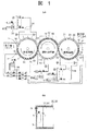
本発明を適用する開口容器用電子線照射装置の原理を図1(a)に示しており、開口容器としてプラスチック製ボトルを用いている。中央に配置する照射処理槽10の側面部に隣接して、前圧力調整槽20と後圧力調整槽30を配置して一体に連結している。これら各槽10、20、30内には、駆動機構(図示せず)により同期させて矢印で示すように回転させる回転搬送体11、21、31を回転可能に配置している。
The principle of the electron beam irradiation apparatus for an open container to which the present invention is applied is shown in FIG. 1A, and a plastic bottle is used as the open container. A front
回転搬送体11、21、31の配置で、各槽10、20、30の外壁面との間に、開口容器1を順に搬送する環状の搬送路を形成している。したがって、開口容器1の生産ライン中には、前処理ラインに連なる前圧力調整槽20、次に照射処理槽10、最後に後処理ラインに連なる後圧力調整槽30が順に配置される状態になる。
With the arrangement of the
各回転搬送体11、21、31は、その外面に開口容器1を保持して搬送する保持機構2を等間隔で複数を設けている。各保持機構2によって、開口容器1は前処理ラインから後処理ラインまでの間で、各槽10、20、30内の回転搬送体11、21、31の相互間を、直立状態のままで順に円滑に受け渡しできる構成としている。
Each of the
照射処理槽10内は、この例では内部を減圧できる耐圧の密封構造とし、この照射処理槽10に真空排気装置13を含む排気手段に連なる配管14を接続し、搬送する開口容器1の周囲の雰囲気を、所定の負圧の状態に維持している。しかも、照射処理槽10に設ける照射区域内で、電子線照射室となる搬送路に対応する部分に、電源に接続する電子線の電子線発生手段40を少なくとも一つを備えている。電子線発生手段40から、負圧状態の照射処理槽10内の電子線照射室となる搬送路に向けて電子線を照射し、搬送移動してくる開口容器1を連続して、順に滅菌処理をする。
In this example, the inside of the
負圧雰囲気の照射処理槽10内で、開口容器1の内外面に電子線を照射して滅菌処理する場合は、電子線発生手段40には150kV以下の加速電圧である低エネルギーのものを使用できる。照射処理槽10内が減圧状態にあると、電子線の減衰が大幅に軽減されるから、低エネルギーの電子線であっても、電子の飛程(飛行距離)が長くなり、しかも電子線の発散量が少なく、開口容器1の内外面への電子線の照射が効果的に行える。
When sterilizing by irradiating the inner and outer surfaces of the open container 1 with an electron beam in the
照射処理槽10内の負圧状態を維持可能にし、電子線の照射を良好に行えるようにするため、開口容器1の搬入側である前処理ライン側及び搬出側である後処理ラインに連なる前圧力調整槽20と後圧力調整槽30は、内部に配置する回転搬送体21、31構造を工夫している。回転搬送体21、31は、それぞれ各保持機構2間を区分する隔壁3を突設し、回転搬送体21、31の回転移動時に、各保持機構2の両側の隔壁3と槽壁面との間で、複数の小区画22、32が形成できる構造としている。
Before being able to maintain the negative pressure state in the
そして、前圧力調整槽20側では、開口容器1を前工程ラインから取り込んだ位置から照射処理槽10に移動する範囲に存在する複数の小区画22を減圧するため、壁面にそれぞれ真空排気装置23を含む排気手段に連なる配管24を接続している。これにより、開口容器1を前工程ラインから前圧力調整槽20に搬入してから、照射処理槽10までの範囲に存在する小区画22を、大気圧から所望の負圧までの圧力調整範囲に管理している。
And on the front
また、同様に後圧力調整槽30側では、開口容器1を照射処理槽10から後工程ラインの位置に移動する範囲に形成される小区画32を減圧するため、壁面にそれぞれ真空排気装置33を含む排気手段に連なる配管34を接続している。これにより、照射処理槽10から後圧力調整槽30の後工程ライン側に、開口容器1が搬出される範囲の小区画32は、所望の負圧から大気圧までの状態となる圧力調整範囲に管理している。
Similarly, on the rear
小区画22、32を形成する各隔壁3は、図1(b)に示すように各槽20、30の外壁との間に微小な間隙Gを有するように設けている。隔壁3は、照射処理槽10から前圧力調整槽20や後圧力調整槽30の大気開放側の各範囲に、複数個存在することになるから、ラビリンスシール構造の働きと同様なる。このため、照射処理槽10から大気圧の外部までの流路抵抗が大きくなるので、特別にシール等を使用する必要もなく、照射処理槽10の負圧状態を維持することができる。
Each
上記の開口容器用電子線照射装置では、開口容器1は前工程ラインからの直立状態のまま各前圧力調整槽20に送り込まれ、順に前圧力調整槽20から照射処理槽10を経て、後圧力調整槽30から後工程ラインに搬出される。開口容器1を搬送中の照射処理槽10部分の所定範囲は照射区域とし、この部分に電子線発生手段40を配置しているから、電子線発生手段40からの電子線で、移動しながら自転する開口容器1を照射し、負圧雰囲気内で滅菌処理する。したがって、飲料等の生産ラインで、直立状態のまま高速で搬送される開口容器1は、低エネルギーの電子線発生手段40を使用して、電子線による開口容器1の滅菌処理を効果的に行うことができる。
In the above electron beam irradiation apparatus for an open container, the open container 1 is sent to each front
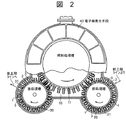
本発明の具体的な開口容器用電子線照射装置の図2の具体例では、照射処理槽10の直径は、一体に連結する前圧力調整槽20及び後圧力調整槽30よりも大きく形成している。この照射処理槽10には、開口容器1の搬送路の照射区域に対向する上面部分の円弧状の範囲に、少なくとも一つの電子線発生手段40を配置し、電源装置(図示せず)に接続している。この構造においても、開口容器1は上述したものと同様に、前工程ライン側から後工程ライン側まで移動する途中で、照射処理槽10の照射区域で電子線の照射を受け、滅菌処理される。
In the specific example of FIG. 2 of the electron beam irradiation apparatus for a specific opening container of the present invention, the diameter of the
本発明を適用した照射処理槽10部分のみを、図3に示している。照射処理槽10は、照射区域となる搬送路に対向する上部に、電子線発生手段40を設けている。電子線発生手段40は、内部に10-5Paのような高真空にする電子線発生源41を備えている。電子線発生源41からの電子線EBは、破線で示すように照射区域の上板10Aに形成して薄膜(図示せず)を設けた照射窓43を通過し、開口容器1の内外面を電子線EBで照射して滅菌処理を実施する。
Only the
回転搬送体11の回転軸12は、照射処理槽10の上板10Aを貫通させ、回転軸12の一部を電子線発生手段40内に突出させている。回転軸12は、照射処理槽10を貫通する部分に、気密を保持できる例えばラビリンス構造の如き回転真空シール部材12Aを設けている。
The rotary shaft 12 of the
電子線発生源41は、良く知られているようにフィラメント44やグリッド板45を有し、これらはリード線50、51や電子線発生手段40を貫通する絶縁端子を介して、電源装置(図示せず)に接続しており、高真空中で発生した電子線を加速し、グリッド板45に設けた放出口46から、照射処理槽10内の照射区域の搬送路に照射する。
As is well known, the electron beam generation source 41 includes a
電子線発生源41のグリッド板45は、本発明により電子線発生手段40内へ突出させた回転軸12に、絶縁支持回転部材47を介して回転可能に取り付けており、回転軸12とグリッド板45とは同一方向に同じ回転をする。このため、回転するグリッド板45には、グリッド電圧供給用の回転接続部材49を設けており、この回転接続部材49にリード線51を接続することで、グリッド板45への電圧供給を行える構成としている。
The
そして、グリッド板45には、照射窓43と対向する位置の同心円上に、複数の放出口46を設けている。しかも、各放出口46は、その間隔(ピッチ)を回転搬送体11に設ける保持機構2の間隔(搬送ピッチ)と同じに形成している。これにより、回転軸12と同じ回転のグリッド板45の放出口46と、回転搬送体11の開口容器1を保持する保持機構2とは、常に同位置を保ったままで回転する構造としているから、放出口46と保持機構2に保持されて移動する開口容器1とが、上下で略同一の位置関係になる。
The
複数の放出口46は、グリッド板45の全周面に保持機構2と同じ間隔で形成するとき、例えば図4に示す如く開口容器1の中心と合わせる内面用孔46Aと、開口容器1の外面用孔46Bとを区分して設けており、しかも開口容器1内に電子線を入れるための中央の内面用孔46Aは、外面用孔46Bに比べて大きく形成している。
When the plurality of discharge ports 46 are formed on the entire circumferential surface of the
また、照射処理槽10の上板10Aに設ける照射窓43も、照射区域の範囲にグリッド板45の放出口46に対抗させて複数を設けている。各照射窓43は、例えば図4に示す如く内面用孔46Aと外面用孔46Bと同様な大きさとする内面用円弧溝43Aと、この内側及び外側の外面用円弧溝43Bとを区分して設けており、これら内面用円弧溝43Aと外面用円弧溝43Bの下部の搬送路に、開口容器1が存在する間は電子線の照射ができる。
Further, a plurality of irradiation windows 43 provided on the
このようにすると、グリッド板45の放出口46と開口容器1を保持した保持機構2が回転移動し、照射処理槽10の照射区域に達し、照射窓43とも略同一の垂直線上に位置している間は、電子線発生手段40内の電子線発生源41から常時放出されている電子線が、開口容器1に向けて照射されて、電子線で開口容器1の内外面に対して滅菌処理を施すことになる。
In this way, the
したがって、電子線発生手段40内の電子線発生源41からの電子線は、確実に開口容器1の内外面に殆ど差がなく、電子線の照射効率を大幅に向上することができる。また、放出口46と保持機構2は、同じ間隔で位置が一致した状態で回転移動する構造であるので、照射窓43と略同一の垂直線上となったときのみ、開口容器1に対して電子線の照射を行うことになる。このため、照射対象の開口容器1に隣接する他の開口容器に対して電子線を照射することがなくなり、電子線を無駄なく照射できるから、電子線照射手段40の電源装置の容量を著しく小さくできる。
Therefore, the electron beam from the electron beam generation source 41 in the electron beam generating means 40 can be reliably improved with little difference between the inner and outer surfaces of the open container 1 and the electron beam irradiation efficiency can be greatly improved. In addition, since the discharge port 46 and the
しかも、放出口46と照射窓43と保持機構2は、これらが略同一の垂直線上となるとき電子線の照射となるので、対象の開口容器のみを滅菌処理できるから、回転搬送体に設ける保持機構の間隔を狭くし、また保持機構2部分に必要としていたシールドや冷却手段等も省略或いは簡略化できる。このため、回転搬送体11ばかりか照射処理槽10の寸法を小さくできるから、開口容器用電子線照射装置の全体を小型化して、経済的に製作することができる。
In addition, since the discharge port 46, the irradiation window 43, and the
なお、上記した実施例の開口容器用電子線照射装置では、照射処理槽10は内部を負圧に維持するものを用いて説明したが、本発明はこのように構成するに限定するものではなく、前記照射処理槽10の照射区域において、回転するグリッド板の放出口46と照射処理槽10の照射窓43と保持機構2に保持される開口容器1とが略同一の垂直線上に位置する構成は、照射処理槽10内を大気圧或いはガス雰囲気とするもの等にも全て適用することができる。
In addition, in the electron beam irradiation apparatus for opening containers of the above-described embodiment, the
1…開口容器、2…保持機構、3…隔壁、10…照射処理槽、11…回転搬送体、12…回転軸、40…電子線発生手段、41…電子線発生源、43…照射窓、43A…内面用円弧溝、43B…外面用円弧溝、45…グリッド板、46…放出口、46A…内面用孔、46B…外面用孔、47…絶縁支持回転材、EB…電子線。 DESCRIPTION OF SYMBOLS 1 ... Opening container, 2 ... Holding mechanism, 3 ... Partition, 10 ... Irradiation processing tank, 11 ... Rotating conveyance body, 12 ... Rotating shaft, 40 ... Electron beam generation means, 41 ... Electron beam generation source, 43 ... Irradiation window, 43A ... Arc groove for inner surface, 43B ... Arc groove for outer surface, 45 ... Grid plate, 46 ... Release port, 46A ... Hole for inner surface, 46B ... Hole for outer surface, 47 ... Insulating support rotating material, EB ... Electron beam.
Claims (4)
Priority Applications (1)
| Application Number | Priority Date | Filing Date | Title |
|---|---|---|---|
| JP2007074328A JP4903608B2 (en) | 2007-03-22 | 2007-03-22 | Electron beam irradiation device for open containers |
Applications Claiming Priority (1)
| Application Number | Priority Date | Filing Date | Title |
|---|---|---|---|
| JP2007074328A JP4903608B2 (en) | 2007-03-22 | 2007-03-22 | Electron beam irradiation device for open containers |
Publications (2)
| Publication Number | Publication Date |
|---|---|
| JP2008230667A JP2008230667A (en) | 2008-10-02 |
| JP4903608B2 true JP4903608B2 (en) | 2012-03-28 |
Family
ID=39903943
Family Applications (1)
| Application Number | Title | Priority Date | Filing Date |
|---|---|---|---|
| JP2007074328A Expired - Fee Related JP4903608B2 (en) | 2007-03-22 | 2007-03-22 | Electron beam irradiation device for open containers |
Country Status (1)
| Country | Link |
|---|---|
| JP (1) | JP4903608B2 (en) |
Families Citing this family (3)
| Publication number | Priority date | Publication date | Assignee | Title |
|---|---|---|---|---|
| JP5738148B2 (en) | 2011-10-17 | 2015-06-17 | 日立造船株式会社 | Electron sterilization equipment for containers using swivel conveyor |
| JP5791459B2 (en) * | 2011-10-17 | 2015-10-07 | 日立造船株式会社 | Shielding structure for electron beam sterilization equipment |
| EP3107586B1 (en) * | 2014-02-19 | 2018-08-08 | Tetra Laval Holdings & Finance S.A. | Sterilization machine and method for sterilizing packaging containers |
Family Cites Families (5)
| Publication number | Priority date | Publication date | Assignee | Title |
|---|---|---|---|---|
| WO1998042385A1 (en) * | 1997-03-26 | 1998-10-01 | Electron Processing Systems, Inc. | Technique for interior electron sterilization of an open mouthed container |
| JP3809627B2 (en) * | 1997-10-08 | 2006-08-16 | アサヒ飲料株式会社 | Electron beam sterilization apparatus and sterilization method for plastic empty container |
| JP3774881B2 (en) * | 1997-11-14 | 2006-05-17 | アサヒ飲料株式会社 | Electron beam sterilizer for plastic empty containers |
| JP2001242297A (en) * | 2000-02-28 | 2001-09-07 | Nissin High Voltage Co Ltd | Electron beam irradiation method and device |
| JP2002171949A (en) * | 2000-12-07 | 2002-06-18 | Ishikawajima Harima Heavy Ind Co Ltd | Electron beam sterilization method and device |
-
2007
- 2007-03-22 JP JP2007074328A patent/JP4903608B2/en not_active Expired - Fee Related
Also Published As
| Publication number | Publication date |
|---|---|
| JP2008230667A (en) | 2008-10-02 |
Similar Documents
| Publication | Publication Date | Title |
|---|---|---|
| EP1956608B1 (en) | Electron beam vacuum apparatus for sterilising containers | |
| EP2100814B1 (en) | Container sterilization apparatus | |
| US8658085B2 (en) | Method for irradiating objects | |
| WO2009139074A1 (en) | Electron beam irradiation device for aperture vessel | |
| CN103770981A (en) | Device for the sterilization of the outside of plastic preforms | |
| US8344332B2 (en) | Electron beam irradiation apparatus for sterilizing sheet material | |
| JP4365835B2 (en) | Electron beam irradiation device for open containers | |
| JP4903608B2 (en) | Electron beam irradiation device for open containers | |
| CN103028126B (en) | Utilize equipment and method that the electric charge carrier source of introducing container is container sterilization | |
| JP4859517B2 (en) | Electron beam irradiation device for open container | |
| JP6563944B2 (en) | Sterilization machine and method for sterilizing package containers | |
| CN101297376B (en) | Electron Beam Irradiation Apparatus for Open Containers | |
| WO2008081672A1 (en) | Sterility keeping method and apparatus for sterilization electron beam irradiating device | |
| JP5179769B2 (en) | Electron beam irradiation device for sterilization of sheet material | |
| JP2007113936A (en) | Method and device for radiating electron beam | |
| JP4372741B2 (en) | Electron beam irradiation method and electron beam irradiation apparatus | |
| JP5082050B2 (en) | Electron beam irradiation device | |
| JP2008079891A (en) | Electron beam irradiation apparatus | |
| JP4910819B2 (en) | Electron beam sterilizer | |
| JP2008237452A (en) | Electron beam irradiation apparatus for sterilization | |
| TW200946405A (en) | Sterilized electron beam irradiation device for containers with openings | |
| TW200946148A (en) | Sterilized electron beam irradiation device for sheet materials |
Legal Events
| Date | Code | Title | Description |
|---|---|---|---|
| A621 | Written request for application examination |
Free format text: JAPANESE INTERMEDIATE CODE: A621 Effective date: 20090728 |
|
| A977 | Report on retrieval |
Free format text: JAPANESE INTERMEDIATE CODE: A971007 Effective date: 20111116 |
|
| TRDD | Decision of grant or rejection written | ||
| A01 | Written decision to grant a patent or to grant a registration (utility model) |
Free format text: JAPANESE INTERMEDIATE CODE: A01 Effective date: 20111213 |
|
| A01 | Written decision to grant a patent or to grant a registration (utility model) |
Free format text: JAPANESE INTERMEDIATE CODE: A01 |
|
| A61 | First payment of annual fees (during grant procedure) |
Free format text: JAPANESE INTERMEDIATE CODE: A61 Effective date: 20120105 |
|
| R150 | Certificate of patent or registration of utility model |
Ref document number: 4903608 Country of ref document: JP Free format text: JAPANESE INTERMEDIATE CODE: R150 Free format text: JAPANESE INTERMEDIATE CODE: R150 |
|
| FPAY | Renewal fee payment (event date is renewal date of database) |
Free format text: PAYMENT UNTIL: 20150113 Year of fee payment: 3 |
|
| FPAY | Renewal fee payment (event date is renewal date of database) |
Free format text: PAYMENT UNTIL: 20150113 Year of fee payment: 3 |
|
| S111 | Request for change of ownership or part of ownership |
Free format text: JAPANESE INTERMEDIATE CODE: R313111 |
|
| FPAY | Renewal fee payment (event date is renewal date of database) |
Free format text: PAYMENT UNTIL: 20150113 Year of fee payment: 3 |
|
| R350 | Written notification of registration of transfer |
Free format text: JAPANESE INTERMEDIATE CODE: R350 |
|
| R250 | Receipt of annual fees |
Free format text: JAPANESE INTERMEDIATE CODE: R250 |
|
| R250 | Receipt of annual fees |
Free format text: JAPANESE INTERMEDIATE CODE: R250 |
|
| R250 | Receipt of annual fees |
Free format text: JAPANESE INTERMEDIATE CODE: R250 |
|
| R250 | Receipt of annual fees |
Free format text: JAPANESE INTERMEDIATE CODE: R250 |
|
| R250 | Receipt of annual fees |
Free format text: JAPANESE INTERMEDIATE CODE: R250 |
|
| R250 | Receipt of annual fees |
Free format text: JAPANESE INTERMEDIATE CODE: R250 |
|
| R250 | Receipt of annual fees |
Free format text: JAPANESE INTERMEDIATE CODE: R250 |
|
| R250 | Receipt of annual fees |
Free format text: JAPANESE INTERMEDIATE CODE: R250 |
|
| LAPS | Cancellation because of no payment of annual fees |