JP4902309B2 - Steering device - Google Patents
Steering device Download PDFInfo
- Publication number
- JP4902309B2 JP4902309B2 JP2006279401A JP2006279401A JP4902309B2 JP 4902309 B2 JP4902309 B2 JP 4902309B2 JP 2006279401 A JP2006279401 A JP 2006279401A JP 2006279401 A JP2006279401 A JP 2006279401A JP 4902309 B2 JP4902309 B2 JP 4902309B2
- Authority
- JP
- Japan
- Prior art keywords
- hydraulic
- hydraulic chamber
- steering
- oil
- cylinder
- Prior art date
- Legal status (The legal status is an assumption and is not a legal conclusion. Google has not performed a legal analysis and makes no representation as to the accuracy of the status listed.)
- Expired - Fee Related
Links
- 239000003921 oil Substances 0.000 claims description 173
- 230000033001 locomotion Effects 0.000 claims description 56
- 230000005540 biological transmission Effects 0.000 claims description 43
- 239000010720 hydraulic oil Substances 0.000 claims description 37
- 238000006243 chemical reaction Methods 0.000 claims description 17
- 230000007935 neutral effect Effects 0.000 claims description 14
- 230000005856 abnormality Effects 0.000 claims description 13
- 238000001514 detection method Methods 0.000 claims description 7
- 230000002441 reversible effect Effects 0.000 claims description 3
- 238000005096 rolling process Methods 0.000 claims description 2
- 238000000034 method Methods 0.000 description 6
- 238000010586 diagram Methods 0.000 description 5
- 239000012530 fluid Substances 0.000 description 5
- 239000007788 liquid Substances 0.000 description 5
- 230000000694 effects Effects 0.000 description 4
- 238000005516 engineering process Methods 0.000 description 3
- 238000005452 bending Methods 0.000 description 2
- 230000007423 decrease Effects 0.000 description 2
- 230000001133 acceleration Effects 0.000 description 1
- 238000013016 damping Methods 0.000 description 1
- 230000003247 decreasing effect Effects 0.000 description 1
- 238000007599 discharging Methods 0.000 description 1
- 230000002427 irreversible effect Effects 0.000 description 1
- 230000010349 pulsation Effects 0.000 description 1
- 238000006557 surface reaction Methods 0.000 description 1
Images


Classifications
-
- B—PERFORMING OPERATIONS; TRANSPORTING
- B62—LAND VEHICLES FOR TRAVELLING OTHERWISE THAN ON RAILS
- B62D—MOTOR VEHICLES; TRAILERS
- B62D3/00—Steering gears
- B62D3/14—Steering gears hydraulic
-
- B—PERFORMING OPERATIONS; TRANSPORTING
- B62—LAND VEHICLES FOR TRAVELLING OTHERWISE THAN ON RAILS
- B62D—MOTOR VEHICLES; TRAILERS
- B62D5/00—Power-assisted or power-driven steering
- B62D5/001—Mechanical components or aspects of steer-by-wire systems, not otherwise provided for in this maingroup
- B62D5/003—Backup systems, e.g. for manual steering
-
- B—PERFORMING OPERATIONS; TRANSPORTING
- B62—LAND VEHICLES FOR TRAVELLING OTHERWISE THAN ON RAILS
- B62D—MOTOR VEHICLES; TRAILERS
- B62D5/00—Power-assisted or power-driven steering
- B62D5/06—Power-assisted or power-driven steering fluid, i.e. using a pressurised fluid for most or all the force required for steering a vehicle
- B62D5/065—Power-assisted or power-driven steering fluid, i.e. using a pressurised fluid for most or all the force required for steering a vehicle characterised by specially adapted means for varying pressurised fluid supply based on need, e.g. on-demand, variable assist
-
- B—PERFORMING OPERATIONS; TRANSPORTING
- B62—LAND VEHICLES FOR TRAVELLING OTHERWISE THAN ON RAILS
- B62D—MOTOR VEHICLES; TRAILERS
- B62D5/00—Power-assisted or power-driven steering
- B62D5/06—Power-assisted or power-driven steering fluid, i.e. using a pressurised fluid for most or all the force required for steering a vehicle
- B62D5/30—Safety devices, e.g. alternate emergency power supply or transmission means to ensure steering upon failure of the primary steering means
Description
本発明は、車両に用いられる運転者に違和感を与えることなくステアリングホイールの操作角に対するタイヤの転舵角の比を運転状況に応じて設定するステアリング装置に関する。 The present invention relates to a steering device that sets a ratio of a turning angle of a tire to an operation angle of a steering wheel in accordance with a driving situation without giving a sense of incongruity to a driver used in a vehicle.
従来、ステアリングホイールと転舵輪とを電気的信号によって接続し、電子制御による性能の向上と、車両への搭載性や車室スペースの確保などを目的としたステアリング技術としてステア・バイ・ワイヤとよばれる技術が知られている。しかし、このような装置では電気的失陥等に対応するための信頼性の確保が不十分なことや、ステアリングホイールへの路面反力のモータによる伝達が困難なことなどから未だ実用化に至っていない。そこで、同等の機能を持つ、ステアリングホイールの操作角と転舵角を連続的に変更可能な車両用のステアリング装置として特開2000−211541号公報等に示されるような、機械式のギヤを用いたものが実用化されている。この種のステアリング装置は高出力の転舵アクチュエータを有し、さらに、ステアリングコラムの途中にギヤとモータを用いた伝達比可変機構が設けられ、モータを制御することで入出力比を調整し、転舵アクチュエータと協調させることでステアリングホイールの操作角に対する転舵輪の転舵角の比を運転状況に応じて設定している。この装置ではステアリングコラムを残しているため信頼性が確保され、反力生成を行う必要もない。 Conventionally, the steering wheel and steered wheels are connected by electrical signals, and steer-by-wire is used as a steering technology for the purpose of improving performance through electronic control, securing mountability in vehicles, and securing cabin space. Technology is known. However, such a device has yet to be put into practical use because of insufficient reliability to cope with electrical failure, etc., and difficult to transmit road surface reaction force to the steering wheel by a motor. Not in. Therefore, a mechanical gear as shown in Japanese Patent Laid-Open No. 2000-211151, etc. is used as a vehicle steering device having an equivalent function and capable of continuously changing the steering wheel operating angle and the turning angle. What has been put into practical use. This type of steering device has a high-output steering actuator, and further, a transmission ratio variable mechanism using a gear and a motor is provided in the middle of the steering column, and the input / output ratio is adjusted by controlling the motor. By coordinating with the steering actuator, the ratio of the turning angle of the steered wheel to the operation angle of the steering wheel is set according to the driving situation. In this device, since the steering column is left, reliability is ensured and there is no need to generate reaction force.
また、特開2003−276617号公報などにあるようにレイアウト自由度の確保を図るためステアリングコラムの代わりにケーブル使うことによるステアリング装置がある。このステアリング装置ではハンドルとラックとの接続に屈曲可能なケーブルを用いている。これによりスペースとレイアウトの自由度を確保している。また、これに舵角比可変機構を組み合わせることでステアリングホイールの操作角に対する転舵輪の転舵角の比を運転状況に応じて設定することが可能なものが知られている。 In addition, as disclosed in Japanese Patent Application Laid-Open No. 2003-276617, there is a steering device that uses a cable instead of a steering column in order to ensure the degree of freedom of layout. In this steering apparatus, a bendable cable is used for connection between the handle and the rack. This ensures space and layout flexibility. Further, there is known one that can set a ratio of a turning angle of a steered wheel with respect to an operation angle of a steering wheel according to a driving situation by combining this with a steering angle ratio variable mechanism.
また、特開2001−122140号公報に示すように油圧配管によってステアリングホイールと転舵輪とを接続したステアリング装置でポンプと弁を使うことによって操舵伝達比可変機構を実現したものがある。さらに、特開2005−82007号公報のように同じく油圧配管で接続したステアリング装置で操舵伝達比可変機構を実現している。これらの装置では先のケーブルを用いた例と同様にスペースとレイアウトの自由度を確保している。 In addition, as shown in Japanese Patent Laid-Open No. 2001-122140, there is a steering system in which a steering transmission ratio variable mechanism is realized by using a pump and a valve in a steering device in which a steering wheel and a steered wheel are connected by hydraulic piping. Further, as in JP-A-2005-82007, a steering transmission ratio variable mechanism is realized by a steering device similarly connected by hydraulic piping. In these devices, the space and the degree of freedom of layout are ensured as in the example using the previous cable.
上記特開2000−211541号公報などに記載の技術ではステアリングホイールの操作角に対する転舵輪の転舵角を自在に制御可能であるが、ステアリングコラムを残しているため、搭載性や車室スペース確保といった現状の一般的な車両の課題を解決することができない。さらに、ステアリングホイールと伝達比可変機構がギヤ、ステアリングコラムで直接接続した構造をしているため伝達比可変機構の作動に伴う振動などが運転者に伝わりやすくそれを抑制するための設計や制御が難しい。 In the technique described in the above Japanese Patent Laid-Open No. 2000-211151, etc., the turning angle of the steered wheel relative to the steering wheel operating angle can be freely controlled. It cannot solve the problems of the current general vehicle. In addition, since the steering wheel and the transmission ratio variable mechanism are directly connected by gears and steering columns, vibrations associated with the operation of the variable transmission ratio mechanism are easily transmitted to the driver, and design and control are required to suppress them. difficult.
また、特開2003−276617号公報などに記載の技術では搭載性や車室スペースの確保をすることができるが、ケーブルの扱いは曲げなどを考慮しながら行わなければならないことや伸びなどが生じることなどから困難であることが予測される。また、上記と同様の理由からケーブルで違和感のない操舵を得るための制御は難しい。 In addition, the technology described in Japanese Patent Application Laid-Open No. 2003-276617 can secure mountability and vehicle interior space, but the cable must be handled in consideration of bending or the like, or stretched. This is expected to be difficult. In addition, for the same reason as described above, it is difficult to perform control for obtaining a steering without a sense of incongruity with a cable.
また、特開2001−122140号公報に記載の技術では操舵伝達比を可変化する際にポンプを用いているが、これでは各油圧回路間で作動油が移動し、各油圧回路の総油量管理が難しく運転者に違和感を与えずに制御を行うことが難しい。そこで、ステアリングホイールに操舵伝達比可変機構の作動による力が加わらないように油路を絞るための弁が更に必要となる。さらにポンプが生成する液圧脈動への対策も必要となる。 Further, in the technique described in Japanese Patent Laid-Open No. 2001-122140, a pump is used when the steering transmission ratio is varied. However, in this case, the hydraulic oil moves between the hydraulic circuits, and the total oil amount of each hydraulic circuit It is difficult to manage and difficult to control without giving the driver a sense of incongruity. Therefore, a valve for restricting the oil passage is further required so that force due to the operation of the steering transmission ratio variable mechanism is not applied to the steering wheel. Furthermore, it is necessary to take measures against the hydraulic pulsation generated by the pump.
また、特開2005−82007号公報に記載の技術では先のステアリングコラムのものと同様に操舵伝達比可変機構がステアリングホイールの入力軸と同軸上に存在し、ボールネジ機構によって接続されるため、操舵伝達比可変機構の作動による振動などが直接ステアリングホイールに伝達されることになりこれが運転者の違和感になる。 Further, in the technique described in Japanese Patent Application Laid-Open No. 2005-82007, the steering transmission ratio variable mechanism exists coaxially with the input shaft of the steering wheel and is connected by the ball screw mechanism as in the case of the previous steering column. Vibrations caused by the operation of the transmission ratio variable mechanism are directly transmitted to the steering wheel, which makes the driver feel uncomfortable.
上記の課題を解決するため、本発明のステアリング装置は、第1油圧室及び第2油圧室を有する入力シリンダと、ステアリングホイールの回転運動を前記入力シリンダの軸方向運動に変換し伝達する際の効率に比べ、前記入力シリンダ側からステアリングホイール側への運動に変換し伝達する際の効率の方が低い伝達機構と、転舵輪に接続され、第3油圧室及び第4油圧室を有する出力シリンダと、前記第1油圧室と前記第3油圧室とを接続する第1油路と、前記第2油圧室と前記第4油圧室とを接続する第2油路と、前記第1油圧室と前記第3油圧室と前記第1油路とを含んで構成される第1油圧回路内の作動油及び前記第2油圧室と前記第4油圧室と前記第2油路とを含んで構成される第2油圧回路内の作動油を行き来させることにより前記第1油圧回路と前記第2油圧回路との油量比率を調整する油量比率調整機構と、前記転舵輪に操舵アシスト力を付与する転舵アクチュエータと、前記油量比率調整機構と前記転舵アクチュエータとを連携制御する制御回路と、を有する。
この構成では前記ステアリングホイールと前記転舵輪とをステアリングコラムで結合する代わりに、作動油の油漏れの少ないシリンダを油圧配管によって結合する。このステアリング装置で前記油量比率調整機構を用い、前記転舵アクチュエータと連携制御することで前記ステアリングホイールの操作角に対する前記転舵輪の転舵角の比を運転状況に応じて設定、つまり操舵伝達比可変機構を実現することができる。また、油圧配管を用いるため自由にレイアウトすることができ、さらにコラムシャフトを廃することができるため搭載性と車室スペースの確保の両方を実現することができる。また、油圧回路を介して各部が接続されるため、ステアリングホイールに油量比調整機構や転舵アクチュエータの作動による振動がステアリングホイールに伝わり難くなり操舵感が向上する。また、ケーブルに比べて油圧配管は曲げなどを考慮に入れなくとも良い分取り扱いが容易である。また、各油路間で作動油を行き来させる前記油量比調整機構により前記転舵アクチュエータとの連携制御をとり易く、運転者に違和感のない前記操舵伝達比可変機構を実現できる。さらに、前記ステアリングホイールの回転運動を前記入力シリンダのピストンの軸方向運動に変換するときの効率に比べ、ピストンの直動運動を回転運動に変換するときの方が低くなるような伝達効率を持つ前記伝達機構を用いることで前記油量比率調整機構の作動による力を、より前記ステアリングホイール側に伝わらないようにできるため運転者に違和感を与えることがなく、また新たに弁などを設ける必要もない。
尚、油量比率調整機構は、第1油圧室を流出入する作動油量に対する第3油圧室を流出入する作動油量の比率と、第2油圧室を流出入する作動油量に対する第4油圧室を流出入する作動油量の比率とを可変にする油量比率可変機構でもある。
前記転舵アクチュエータの動作異常を検出する異常検出回路を更に有するとよい。
この構成によれば、前記転舵アクチュエータが電気的な失陥等で動作の継続が不可能であることを検知し、その場合には前記転舵アクチュエータを第1油圧回路,第2油圧回路で伝達される操舵力を阻害しない状態にすることで転舵を可能とする。
In order to solve the above-described problems, a steering device according to the present invention converts an input cylinder having a first hydraulic chamber and a second hydraulic chamber and a rotational motion of a steering wheel into an axial motion of the input cylinder and transmits it. An output cylinder having a third hydraulic chamber and a fourth hydraulic chamber connected to the steered wheels and a transmission mechanism having a lower efficiency in converting and transmitting the movement from the input cylinder side to the steering wheel side compared to the efficiency A first oil passage connecting the first hydraulic chamber and the third hydraulic chamber, a second oil passage connecting the second hydraulic chamber and the fourth hydraulic chamber, and the first hydraulic chamber It is comprised including the hydraulic oil in the 1st hydraulic circuit comprised including the said 3rd hydraulic chamber and the said 1st oil path, the said 2nd hydraulic chamber, the said 4th hydraulic chamber, and the said 2nd oil path. By moving the hydraulic oil in the second hydraulic circuit An oil amount ratio adjusting mechanism that adjusts an oil amount ratio between the first hydraulic circuit and the second hydraulic circuit, a turning actuator that applies a steering assist force to the steered wheels, the oil amount ratio adjusting mechanism, and the rolling amount A control circuit that controls the rudder actuator in a coordinated manner.
In this configuration, instead of connecting the steering wheel and the steered wheel with a steering column, a cylinder with less hydraulic oil leakage is connected by hydraulic piping. The steering device uses the oil amount ratio adjusting mechanism, and controls the steering angle of the steered wheel with respect to the steering wheel operating angle by controlling in cooperation with the steering actuator, that is, steering transmission. A variable ratio mechanism can be realized. Further, since hydraulic piping is used, the layout can be freely performed, and the column shaft can be eliminated, so that both mountability and securing of vehicle compartment space can be realized. Further, since each part is connected via the hydraulic circuit, vibration due to the operation of the oil amount ratio adjusting mechanism and the steering actuator is hardly transmitted to the steering wheel, and the steering feeling is improved. Also, compared to cables, hydraulic piping is easier to handle because it does not need to take bending into consideration. In addition, it is possible to realize the steering transmission ratio variable mechanism that makes it easy to perform cooperative control with the steering actuator by means of the oil amount ratio adjusting mechanism that moves hydraulic oil back and forth between the oil passages, and that does not give the driver a sense of incongruity. Further, the transmission efficiency is lower when converting the linear motion of the piston into the rotational motion than the efficiency when converting the rotational motion of the steering wheel into the axial motion of the piston of the input cylinder. By using the transmission mechanism, the force due to the operation of the oil amount ratio adjusting mechanism can be prevented from being transmitted more to the steering wheel side, so that the driver does not feel uncomfortable and it is also necessary to newly provide a valve or the like. Absent.
The oil amount ratio adjusting mechanism is a ratio of the amount of hydraulic oil flowing in and out of the third hydraulic chamber to the amount of hydraulic oil flowing in and out of the first hydraulic chamber and a fourth amount of hydraulic oil flowing in and out of the second hydraulic chamber. It is also an oil quantity ratio variable mechanism that makes the ratio of the hydraulic oil quantity flowing into and out of the hydraulic chamber variable.
It is preferable to further include an abnormality detection circuit that detects an operational abnormality of the steering actuator.
According to this configuration, it is detected that the operation of the steering actuator cannot be continued due to an electrical failure or the like, and in that case, the steering actuator is detected by the first hydraulic circuit and the second hydraulic circuit. Steering is enabled by making the transmitted steering force not disturbed.
さらに、前記油量比率調整機構は、前記異常検出回路が異常を検出するとき、前記出力シリンダの液圧を制御することにより転舵輪に操舵アシスト力を付与するようにするとよい。
これによって、前記転舵アクチュエータが作動しない場合にも運転者の負担を最小限に抑えることができる。
また、前記油量比率調整機構は、シリンダチューブと、このシリンダチューブを前記第1油圧回路に接続された第5油圧室と前記第2油圧回路に接続された第6油圧室とに区画するピストンと、電動モータと、この電動モータの回転方向の運動を前記ピストンの軸方向運動へ変換する変換ギヤと、から構成され、前記変換ギヤは、前記ピストン側から前記電動モータ側への力の伝達を抑制する非可逆性を有するとよい。
前記油量比率調整機構をこのような構成とすることにより、前記第1油圧回路と前記第2油圧回路とが完全に独立した油圧回路とすることができ、各部のピストンの動きによる作動油収支の管理が容易となるため、前記油量比率調整機構と前記転舵アクチュエータの連携制御が容易となる。また、前記非可逆性のギヤにより前記油量比率調整機構の前記ピストンにかかる圧力によって意図せずに前記モータが逆回転することを防止することもできる。
また、前記油量比率調整機構は、ステアリングホイールと転舵輪との間に中立位置のずれが生じた場合には、前記転舵アクチュエータと連携してこのずれを補正するとよい。
また、ステアリングホイールの操舵角を検出する操舵角センサと、転舵輪の転舵角を検出する転舵角センサと、を更に備え、前記油量比率調整機構は、前記操舵角センサと前記転舵角センサのセンサ出力に基づき前記中立位置のずれを補正するとよい。
このような構成にすることで、各油圧回路からのわずかな油漏れなどによる前記中立位置に僅かなずれが生じた場合に、それを検知することができるのに加え、運転者に違和感を与えることなく中立位置の補正を行うことができる。
また、前記転舵アクチュエータは、転舵輪に接続され、1対の油圧室を有するパワーシリンダと、電動モータによって正逆回転駆動され、前記パワーシリンダに選択的に液圧を供給する正逆回転ポンプと、から構成されるとよい。
前記出力シリンダと前記パワーシリンダとは互いに並列に配置されるとよい。
この構成によって、車両の幅が不足し、前記出力シリンダと前記パワーシリンダを直列に配置することができない場合にも本発明のステアリング装置を車両に搭載することができる。
また、リザーバタンクと、このリザーバタンクと前記第1油圧回路とを接続する第1接続通路と、この第1接続通路に設けられ、前記リザーバタンク側から前記第1油圧回路側への油の流れのみを許容する第1一方向弁と、前記リザーバタンクと前記第2油圧回路とを接続する第2接続通路と、この第2接続通路に設けられ、前記リザーバタンクから前記第2油圧回路側への油の流れのみを許容する第2一方向弁と、を更に有するとよい。
このような構成によって、前記第1,第2の油圧回路から作動油が微量に漏れた場合にその不足分を補うことができる。
また、前記第1油圧室および前記第2油圧室の液圧を検出する液圧センサを更に備え、前記制御回路は前記液圧センサのセンサ出力に基づき前記転舵アクチュエータを制御するとよい。
これによって、トルクセンサなどを前記転舵軸等に新たに設けることなく、運転者の操作力を検出することができる。
また、前記異常検出回路は前記液圧センサのセンサ出力に基づき第1油圧回路および第2油圧回路の異常を検出するとよい。
また、前記伝達機構は、前記第1油圧室または第2油圧室の圧力が高いほど前記入力シリンダ側から前記ステアリングホイールへの伝達効率が低くなるようにするとよい。
このことで、請求項3に記載のように前記転舵アクチュエータが故障の際に、前記油量比率調整機構で操舵アシスト力を付与するときに、前記入力シリンダの圧力が上昇し、前記ステアリングホイールへの反力が過大になることで、ステアリングホイールが大きな力で勝手に回転し、運転者の操作を妨げることのないようにすることができる。
Further, the oil amount ratio adjusting mechanism may apply a steering assist force to the steered wheels by controlling the hydraulic pressure of the output cylinder when the abnormality detection circuit detects an abnormality.
Thereby, even when the steering actuator does not operate, the burden on the driver can be minimized.
The oil amount ratio adjusting mechanism includes a cylinder tube and a piston that divides the cylinder tube into a fifth hydraulic chamber connected to the first hydraulic circuit and a sixth hydraulic chamber connected to the second hydraulic circuit. And an electric motor and a conversion gear for converting the movement of the electric motor in the rotational direction into the axial movement of the piston, and the conversion gear transmits force from the piston side to the electric motor side. It is good to have irreversibility to suppress the above.
By configuring the oil amount ratio adjusting mechanism in this way, the first hydraulic circuit and the second hydraulic circuit can be made completely independent hydraulic pressure circuits, and the hydraulic oil balance by the movement of the pistons of each part This makes it easy to manage the oil amount ratio adjusting mechanism and the turning actuator. In addition, the irreversible gear can prevent the motor from rotating in the reverse direction unintentionally due to the pressure applied to the piston of the oil amount ratio adjusting mechanism.
The oil amount ratio adjusting mechanism may correct the deviation in cooperation with the steering actuator when a neutral position deviation occurs between the steering wheel and the steered wheel.
In addition, a steering angle sensor that detects a steering angle of a steering wheel, and a turning angle sensor that detects a turning angle of a steered wheel, and the oil amount ratio adjusting mechanism includes the steering angle sensor and the steering wheel. The neutral position deviation may be corrected based on the sensor output of the angle sensor.
With this configuration, when a slight shift occurs in the neutral position due to a slight oil leak from each hydraulic circuit, it can be detected, and the driver feels uncomfortable. The neutral position can be corrected without this.
The steered actuator is connected to steered wheels and has a pair of hydraulic chambers, and a forward / reverse rotary pump that is driven forward / reversely by an electric motor and selectively supplies hydraulic pressure to the power cylinder. It is good to be composed of
The output cylinder and the power cylinder may be arranged in parallel with each other.
With this configuration, the steering device of the present invention can be mounted on a vehicle even when the width of the vehicle is insufficient and the output cylinder and the power cylinder cannot be arranged in series.
Also, a reservoir tank, a first connection passage connecting the reservoir tank and the first hydraulic circuit, and an oil flow provided in the first connection passage from the reservoir tank side to the first hydraulic circuit side are provided. A first one-way valve that allows only a first connection, a second connection passage that connects the reservoir tank and the second hydraulic circuit, and a second connection passage that is provided in the second connection passage, from the reservoir tank to the second hydraulic circuit side. And a second one-way valve that allows only the oil flow.
With such a configuration, when a small amount of hydraulic fluid leaks from the first and second hydraulic circuits, the shortage can be compensated.
Moreover, it is preferable to further include a hydraulic pressure sensor that detects hydraulic pressures of the first hydraulic chamber and the second hydraulic chamber, and the control circuit controls the steering actuator based on a sensor output of the hydraulic pressure sensor.
Accordingly, it is possible to detect the operating force of the driver without newly providing a torque sensor or the like on the steered shaft or the like.
The abnormality detection circuit may detect an abnormality in the first hydraulic circuit and the second hydraulic circuit based on the sensor output of the hydraulic pressure sensor.
The transmission mechanism may be configured such that the transmission efficiency from the input cylinder side to the steering wheel decreases as the pressure in the first hydraulic chamber or the second hydraulic chamber increases.
As a result, when the steering actuator fails as described in claim 3, when the steering amount is applied by the oil amount ratio adjusting mechanism, the pressure of the input cylinder increases, and the steering wheel As the reaction force against the steering wheel becomes excessive, the steering wheel can be rotated freely with a large force so that the driver's operation is not hindered.
あるいは、本発明のステアリング装置は、第1油圧室及び第2油圧室を有する入力シリンダと、ステアリングホイールの回転運動を前記入力シリンダの軸方向運動に変換し伝達する際の効率に比べ、前記入力シリンダ側からステアリングホイール側への運動に変換し伝達する際の効率の方が低い伝達機構と、転舵輪に接続され、第3油圧室及び第4油圧室を有する出力シリンダと、前記第1油圧室と前記第3油圧室とを接続する第1油路と、前記第2油圧室と前記第4油圧室とを接続する第2油路と、前記転舵輪に操舵アシスト力を付与する転舵アクチュエータと、前記第1油圧室と前記第3油圧室と前記第1油路とを含んで構成される第1油圧回路内の作動油及び前記第2油圧室と前記第4油圧室と前記第2油路とを含んで構成される第2油圧回路内の作動油を行き来させることにより、前記ステアリングホイールの操作量に対する前記転舵アクチュエータの動作量の不一致を補正する補正機構と、を有する。
前記補正機構は前記転舵アクチュエータの動作量に応じて駆動制御されるとよい。
これにより運転状況に応じて運転者の要求によらず前記転舵アクチュエータを制御し、転舵量を増減した場合に、前記補正機構により前記ステアリングホイール側の前記入力シリンダへ伝達される油量を変化しないように制御する。これによって前記ステアリングホイールに前記転舵アクチュエータが操作されたことが伝達されないようにし、運転者に違和感を与えることがない。
また、前記補正機構はステアリングホイールと転舵輪との間に中立位置のずれが生じた場合には、このずれを補正するとよい。
Alternatively, the steering device according to the present invention has an input cylinder having a first hydraulic chamber and a second hydraulic chamber, and the input cylinder in comparison with the efficiency when converting the rotational motion of the steering wheel into the axial motion of the input cylinder and transmitting it. A transmission mechanism having a lower efficiency in converting and transmitting the movement from the cylinder side to the steering wheel side, an output cylinder connected to the steered wheels and having a third hydraulic chamber and a fourth hydraulic chamber, and the first hydraulic pressure A first oil passage that connects a chamber and the third hydraulic chamber, a second oil passage that connects the second hydraulic chamber and the fourth hydraulic chamber, and a steering that applies a steering assist force to the steered wheels. Actuating oil in the first hydraulic circuit including the actuator, the first hydraulic chamber, the third hydraulic chamber, and the first oil passage, the second hydraulic chamber, the fourth hydraulic chamber, and the first hydraulic chamber. And a second oil passage including two oil passages. By traversing the working oil in the hydraulic circuit, having a correction mechanism for correcting the discrepancy amount of operation of the steering actuator with respect to the operation amount of the steering wheel.
The correction mechanism may be driven and controlled according to the operation amount of the steering actuator.
As a result, the amount of oil transmitted to the input cylinder on the steering wheel side by the correction mechanism when the steering actuator is controlled regardless of the driver's request according to the driving situation and the steering amount is increased or decreased. Control so that it does not change. As a result, the fact that the steering actuator has been operated is not transmitted to the steering wheel, and the driver does not feel uncomfortable.
Further, when the neutral position shift occurs between the steering wheel and the steered wheel, the correction mechanism may correct this shift.
あるいは、第1油圧室及び第2油圧室を有する入力シリンダと、ステアリングホイールの回転運動を前記入力シリンダの軸方向運動に変換し伝達するボールねじ機構と、転舵輪に接続され、第3油圧室及び第4油圧室を有する出力シリンダと、前記第1油圧室と前記第3油圧室とを接続する第1油路と、前記第2油圧室と前記第4油圧室とを接続する第2油路と、前記第1油圧室,第3油圧室及び第1油路を含んで構成される第1油圧回路に接続される第5油圧室と、前記第2油圧室,第4油圧室及び第2油路を含んで構成される第2油圧回路に接続される第6油圧室とを備え、これら第5油圧室と第6油圧室との容積比率を調整することにより前記第1油圧回路と前記第2油圧回路との油量比率を調整する油量比率調整機構と、前記転舵輪に操舵アシスト力を付与する転舵アクチュエータと、前記油量比率調整機構と前記転舵アクチュエータとを連携制御する制御回路と、を有する。
この構成により、前記ステアリングホイールの回転運動を前記入力シリンダの軸方向運動に変換し、前記第1,第2油圧回路を介して油圧力を前記出力シリンダへ伝達し前記転舵輪を転舵する。さらにこの前記第1,第2油圧回路に接続する前記油量比率調整機構をシリンダとすることで前記第1,第2油圧回路を完全に独立させることができるため前記油量比率調整機構の動作に伴う各部の油量収支の管理をしやすく、転舵アクチュエータとの連携制御が容易となる。また、同様の理由からステアリングホイールに油量比率調整機構の動作に伴う力が伝達しないように制御するのが容易のため、弁などが必要ない。
また、前記油量比率調整機構と前記転舵アクチュエータとは隣接配置されるとよい。
このことにより、搭載性を向上させることができる。
また、1対の油圧室を有し、前記ボールねじ機構に接続された第2入力シリンダと、転舵輪に接続され、1対の油圧室を有する第2出力シリンダと、前記第2入力シリンダと前記第2出力シリンダの夫々の油圧室同士が接続されることにより構成される第3油圧回路および第4油圧回路に夫々接続される第7油圧室と第8油圧室とを更に備え、前記油量比率調整機構は前記第5油圧室と前記第6油圧室との容積比率の調整および前記第7油圧室と前記第8油圧室との容積比率の調整をするとよい。
この構成により、ステアリングホイールと転舵輪との接続を二重の油圧回路にすることができるため、高度な信頼性を確保することができる。
また、前記第1油圧回路と前記第3油圧回路とを接続する第1バランス油路と、この第1バランス油路に設けられた第1フリーピストンと、前記第2油圧回路と前記第4油圧回路とを接続する第2バランス油路と、この第2バランス油路に設けられた第2フリーピストンと、を更に有するとよい。
この構成により、信頼性確保のために2重系にした前記油圧回路で、同方向の力を伝達する前記油圧回路間で微量な作動油の漏れなどから同じ力が伝達できないときに油量のバランスをとることができるため伝達される力を均一化することができる。
Alternatively, an input cylinder having a first hydraulic chamber and a second hydraulic chamber, a ball screw mechanism that converts and transmits the rotational motion of the steering wheel into the axial motion of the input cylinder, and a steered wheel are connected to the third hydraulic chamber. And an output cylinder having a fourth hydraulic chamber, a first oil passage connecting the first hydraulic chamber and the third hydraulic chamber, and a second oil connecting the second hydraulic chamber and the fourth hydraulic chamber. A fifth hydraulic chamber connected to a first hydraulic circuit including a passage, the first hydraulic chamber, the third hydraulic chamber, and the first hydraulic passage; the second hydraulic chamber; the fourth hydraulic chamber; A sixth hydraulic chamber connected to a second hydraulic circuit including two oil passages, and adjusting the volume ratio between the fifth hydraulic chamber and the sixth hydraulic chamber, An oil amount ratio adjusting mechanism for adjusting an oil amount ratio with the second hydraulic circuit, and the steered wheels Having a steering actuator that imparts a steering assist force, and a control circuit for cooperation control and the steering actuator and the flow rate control mechanism.
With this configuration, the rotational motion of the steering wheel is converted into the axial motion of the input cylinder, and hydraulic pressure is transmitted to the output cylinder via the first and second hydraulic circuits to steer the steered wheels. Further, since the oil amount ratio adjusting mechanism connected to the first and second hydraulic circuits is a cylinder, the first and second hydraulic circuits can be completely independent, so that the operation of the oil amount ratio adjusting mechanism is performed. This makes it easy to manage the oil balance of each part, and facilitates cooperative control with the steering actuator. Further, for the same reason, it is easy to control the steering wheel so that the force accompanying the operation of the oil amount ratio adjusting mechanism is not transmitted to the steering wheel, so a valve or the like is not necessary.
The oil amount ratio adjusting mechanism and the steering actuator may be disposed adjacent to each other.
Thereby, the mountability can be improved.
A second input cylinder having a pair of hydraulic chambers and connected to the ball screw mechanism; a second output cylinder connected to a steered wheel and having a pair of hydraulic chambers; and the second input cylinder; And further comprising a seventh hydraulic chamber and an eighth hydraulic chamber respectively connected to a third hydraulic circuit and a fourth hydraulic circuit configured by connecting the respective hydraulic chambers of the second output cylinder. The quantity ratio adjusting mechanism may adjust the volume ratio between the fifth hydraulic chamber and the sixth hydraulic chamber and the volume ratio between the seventh hydraulic chamber and the eighth hydraulic chamber.
With this configuration, since the connection between the steering wheel and the steered wheel can be a double hydraulic circuit, high reliability can be ensured.
In addition, a first balance oil passage connecting the first hydraulic circuit and the third hydraulic circuit, a first free piston provided in the first balance oil passage, the second hydraulic circuit, and the fourth hydraulic pressure. It is good to further have the 2nd balance oil passage which connects a circuit, and the 2nd free piston provided in this 2nd balance oil passage.
With this configuration, in the hydraulic circuit that is a double system for ensuring reliability, the oil amount is reduced when the same force cannot be transmitted between the hydraulic circuits that transmit the force in the same direction due to a small amount of hydraulic fluid leakage or the like. Since the balance can be achieved, the transmitted force can be made uniform.
また、前記第1フリーピストンおよび前記第2フリーピストンは前記油量比率調整機構内部に設けられるとよい。 The first free piston and the second free piston may be provided in the oil amount ratio adjusting mechanism.
本発明によれば、ハンドルの操作角に対するタイヤの転舵角の比を運転状況に応じて設定することができるステアリング装置において、ケーブルに比べて取り扱いが容易な油圧回路を用いることで、故障に対する信頼性を確保しつつ、搭載性の確保と車室スペース拡張を実現することができる。さらに、ハンドルの操作角に対するタイヤの転舵角の比を運転状況に応じた設定を運転者に違和感を与えずに変更することを可能とする。さらに、油圧を利用して各部を接続しているため、良好な操舵感を得ることができる。また、各油路間の作動油を行き来させるような油量比率調整機構と、さらにステアリングホイールの回転運動を前記入力シリンダの軸方向運動に変換し伝達する際の効率に比べ、前記入力シリンダ側から前記ステアリングホイール側への運動に変換し伝達する際の効率の方が低い伝達機構とにより油圧回路に新たに弁などを設けずとも運転者に違和感を与えない伝達比可変制御が可能となる。 According to the present invention, in the steering device that can set the ratio of the steering angle of the tire to the operation angle of the steering wheel in accordance with the driving situation, by using a hydraulic circuit that is easier to handle than the cable, While ensuring reliability, it is possible to ensure mountability and expand vehicle compartment space. Furthermore, it is possible to change the ratio of the steering angle of the tire with respect to the operation angle of the steering wheel according to the driving situation without causing the driver to feel uncomfortable. Furthermore, since each part is connected using hydraulic pressure, a good steering feeling can be obtained. In addition, an oil amount ratio adjusting mechanism for moving hydraulic oil between the oil passages, and further, the input cylinder side compared to the efficiency when the rotational movement of the steering wheel is converted into the axial movement of the input cylinder and transmitted. The transmission ratio variable control that does not give the driver a sense of incongruity without providing a new valve or the like in the hydraulic circuit is possible by the transmission mechanism having a lower efficiency in converting and transmitting the movement to the steering wheel side. .
以下、実施例を説明する。 Examples will be described below.
本発明を実施するための最良の形態を、実施例1に基づいて説明する。図1に本発明に係るステアリング装置10の全体構成図を示す。同図において符号11はステアリングホイールであって入力軸12を介して入力シリンダ13と接続されている。入力シリンダ
13はピストン14によって、第1油圧室15と第2油圧室16に液密に区画されている。ステアリングホイール11の回転運動は伝達機構17によってピストン14の直動運動に変換される。
The best mode for carrying out the present invention will be described based on the first embodiment. FIG. 1 shows an overall configuration diagram of a
また、転舵輪18はナックルアーム19を介して転舵軸20に接続され、転舵軸20には転舵アクチュエータ21の出力部としてパワーシリンダ22が設けられ、転舵軸20と平行に出力シリンダ23が設けられる。出力シリンダ23は内部に転舵軸20と結合したピストン24を持ち、これによって第3油圧室25と第4油圧室26に液密に区画されている。入力シリンダ13の第1油圧室15と出力シリンダ23の第3油圧室25は第1油路27によって、入力シリンダ13の第2油圧室16と出力シリンダ23の第4油圧室
26は第2油路28によってそれぞれ接続される。また、油量比率調整機構29が第1油圧室15と第3油圧室25と第1油路27とで構成される第1油圧回路と第2油圧室16と第4油圧室26と第2油路28とで構成される第2油圧回路に接続され、第1油圧回路と第2油圧回路の作動油を行き来させることで入力シリンダ13と出力シリンダ23との間を移動する作動油量の比率を調整する。ここで、油量比率調整機構29はシリンダ30とシリンダ30を第5油圧室31と第6油圧室32に区画するピストン33とを有し、変換ギヤ34と調整軸35とを介してモータ36と接続される。
Further, the steered
また、パワーシリンダ22は転舵軸20と結合したピストン37により一対の油圧室
38に液密に区画される。油圧室38には転舵アクチュエータ用の油路39を介してポンプ40が接続され、さらに油路39は逆止弁41を介してリザーバタンク42と接続される。ポンプ40はモータ43により駆動し、油圧室38へ作動油を選択的に吐出することによって転舵軸20へ転舵アシスト力を付与する。
The
上記のような構成を有するステアリング装置10ではステアリングホイール11と転舵輪18が第1油圧回路と第2油圧回路とによって接続される。第1油圧回路と第2油圧回路は通常操舵時には運転者の操舵力を転舵輪18へ伝達する役割と、転舵輪18に加わる路面からの反力をステアリングホイール11に伝える役割とを果たす。さらに、図1に示すように第1油路26,第2油路27の一部にゴム付ホースなどの柔軟な配管44を用いることで油圧回路を自由に配置することもできる。
In the
また、操舵時には運転者の操舵量を舵角センサやトルクセンサなど45で検出し、それに基づいてコントローラ46で必要な転舵アシスト力を算出し、モータ43により、ポンプ40を駆動し、パワーシリンダ22内の油圧室38の圧力を制御することで運転者の転舵をアシストする。
Further, the steering amount of the driver is detected by a steering angle sensor, a torque sensor, etc. 45 at the time of steering, and a necessary steering assist force is calculated by the
さらに、運転状況を速度,加速度,ヨーレイトなどを車両のセンサ52から読み取りコントローラ46でステアリングホイール11の操作角に対する転舵輪18の転舵角の伝達比を変更したほうが運転者によって好ましいと判断した場合には油量比率調整機構29と転舵アクチュエータ21とを連携して制御することにより運転者に違和感を与えずに伝達比を変更することができる。
Further, when it is determined by the driver that the speed, acceleration, yaw rate, etc. of the driving situation is read from the
例えば、駐車時などには小さなステアリングホイール11の操作角に対して転舵輪18の転舵角が大きくなると運転者の負担が少ない。このような伝達比を実現するためにはステアリングホイール11の操作角に対する転舵アクチュエータ21による転舵輪18の操作量を通常時より多くする方法をとる。しかし、通常の伝達比のままだと、パワーシリンダ22と出力シリンダ23のピストンは同じ動きをするため第1油路27,第2油路28には通常時より多くの作動油が移動し、ステアリングホイール11に急に大きな力が加わることになり、これが運転者にとって違和感となる。そこで、転舵アクチュエータ21を制御するのと同時に油量比率調整機構29を制御することで第1油路27,第2油路28を入力シリンダ13側へ移動する作動油の量が変化しないようにする。具体的に車庫入れ時に図1に向って入力シリンダ13が右に動くように運転者がステアリングホイール11を操作した場合を想定する。その場合、操舵状態をセンサ45で、車両状況をセンサ52により読み取り、コントローラ46で伝達比を変えることを決定し、ステアリングホイール11の操作角に対して転舵輪18の転舵角が通常より大きくなるように転舵アクチュエータ21によりパワーシリンダ22のピストン37を図面に向かって左側に大きく操作する。これによって第1油路27,第2油路28を移動する作動油が増加するが、その量を転舵アクチュエータ21の制御量から求め、移動作動油の増加分を吸収できるだけ油量比率調整機構29のピストン33を下側に移動させることで各油路から入力シリンダ13へ移動する作動油の量が変化しないようにすることができる。これによって、ステアリングホイール11への入力に対する転舵角を通常時よりも大きくしても、運転者に違和感を与えることがない。
For example, when the vehicle is parked or the like, the burden on the driver is reduced when the turning angle of the steered
また、例えば高速走行時にはステアリングホイール11の操作角に対して転舵輪18の転舵角が小さいと安定した走行が実現できることが知られている。このためにはステアリングホイール11の操舵角に対する転舵アクチュエータ21による転舵輪18の操作量を通常時より少なくするような伝達比を実現できればよい。しかし、パワーシリンダ22と出力シリンダ23は同じ動きをするため、この操作を行うことによって第1油路27,第2油路28には通常時より少ない作動油しか移動しなくなり、運転者は急にステアリングホイールが重くなったように感じ、これを違和感として受け取る。そこで、上記の例と同様に転舵アクチュエータ44を制御するのと同時に油量比率調整機構29を操作することで第1油路27,第2油路28をステアリングホイール11側に移動する作動油の量が変化しないように調整する。具体的に速度が上がったときに図1で入力シリンダ13が右に動くように運転者がステアリングホイール11を操作した場合を想定する。その場合、車両状況をセンサにより読み取り、コントローラ46でステアリングホイール11の操作角に対して転舵輪18の転舵角が通常より小さくなるように転舵アクチュエータ21によりパワーシリンダ22のピストン37を図面に向かって左側に通常より小さく操作する。これによって第1油路27,第2油路28を移動する作動油が入力シリンダ13から移動する作動油より少なくなるが、その減少量を転舵アクチュエータ21の駆動量から求め、移動作動油の減少分を補うように油量比率調整機構29のピストン33を上側に移動させることで油路から入力シリンダ13へ移動する油量が変化しないようにすることができる。
In addition, for example, it is known that stable traveling can be realized when the turning angle of the steered
また、同様の方法を用いて、車両の状態から運転者の操作によらず転舵輪18を操作したほうが良いと判断した場合にも、本方式を適用することができる。つまり、ステアリングホイール11が操作されない場合に操舵アクチュエータ21で転舵輪18を転舵した場合、各油路27,28に作動油の移動が発生するが、その移動量を吸収できる分だけ油量比率調整機構29を制御することで入力シリンダ13への作動油の移動がないようにし、ステアリングホイール11に力が加わらないようにする。これにより、運転者に違和感を与えることなく転舵輪18を制御することが可能となる。
Further, this method can be applied even when it is determined that it is better to operate the steered
また、本実施例の図面に示しているように油量比率調整機構29は油圧シリンダを用いた方式であるため、ピストン33の位置を検出することにより、油量比率調整機構29に流出入する油量を把握でき、先に示したような操舵伝達比を可変化する際に各油路を移動する油量を把握することが容易となり、これにより第1油圧室を流出入する油量と第3油圧室を流出入する油量との差分を正確に把握できる。従って、正確な制御が行えるので、運転者に違和感を与えることがない制御の実現が容易である。
Further, as shown in the drawing of the present embodiment, the oil amount
また、これに加えて、後述するような入力シリンダ13の構成により伝達機構17はステアリングホイールの回転運動を入力シリンダ13の軸方向運動に変換する伝達効率に対して、逆に入力シリンダ13側からステアリングホイール11側への運動に変換する伝達効率を低くすることによって、急激にステアリングホイール11を動かした場合などに、油量比率調整機構29と操舵アクチュエータ21の連携制御のタイミングが万が一合わないことがあったとしても、それがステアリングホイールにはほとんど伝達されず運転者が違和感を覚えることがないようにすることができる。
In addition to this, with the configuration of the
また、転舵アクチュエータ21が電気的な故障などにより作動しなくなった場合には、転舵アクチュエータ21のモータ43への制御電流値の変化やセンサの検出値から異常を読み取り、転舵を阻害しない状態にする。さらに、大きく転舵する場合などで大きな操舵力が必要な場合には油量比率調整機構29を制御することで操舵をアシストする。
Further, when the
また、油圧回路から微量な作動油もれ等によりステアリングホイール11の中立位置と転舵輪18の中立位置とにずれが生じた場合、それを、操舵角センサ42とストロークセンサ47の検出値の比較により読み取る。もし中立位置のずれが生じている場合には、転舵アクチュエータ21と油量比率調整機構29とを連携して制御することで運転者が気づかない内に中立位置を補正することができる。また、このときに転舵輪18の中立位置のずれを判断するセンサはストロークセンサ43ではなく、車両の状態量を検出するセンサ52によるものとしても良い。
Further, when a deviation occurs between the neutral position of the
また、第1油圧回路と第2油圧回路とリザーバタンク48とを接続する接続油路49と作動油の流れを一方向に制限する一方向弁50を設けることによって、油圧回路から微量な作動油もれが生じた場合、漏れによる作動油の不足分をリザーバタンクから補給することができる。
Further, by providing a
また、ステアリングホイール11への操作トルクは油圧回路に設けられた液圧センサ
51で検出するようにすることもできる。このような構成により操作トルクを検出できるばかりではなく、油圧回路の失陥も検出することが可能となり、信頼性が向上する。
Further, the operation torque to the
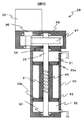
また、本実施例で用いる入力シリンダ13は例えば図2に示すような構成とする。入力シリンダ13には前述のように入力軸12を介してステアリングホイール11が接続される。入力シリンダ13のピストン14は後述するボールナット61を挟み込んだ一対のピストン14a,14bによって構成されている。各ピストン14a,14bの外周には入力シリンダ13との隙間をシールするシールリング62が取り付けられ、同じく内周にも入力軸12との隙間をシールするシールリング62が取り付けられている。また、入力シリンダ13の上部と下部の入力軸12と入力シリンダ13との間にはボールベアリング
63が設けられ、入力軸12を回転可能に支持する。さらに、入力軸12が貫通する入力シリンダ13の液密性を確保するために入力軸12の回転を許容しつつ入力軸12との隙間をシールするシールリング64が取り付けられている。
Further, the
ボールナット61と入力軸12にはらせん状に溝を形成し、そこに複数個のボール65を配置することでボールねじ機構を構成する。このボールねじ機構を用いることでボールナット61と接続されたピストン14が入力軸12の回転により軸方向へ移動する。また、ステアリングホイール11の回転軸と入力軸の間に所定の増速比のギヤ66を設け、ピストン14のストロークを確保するような構成としてもよい。
A ball screw mechanism is formed by forming a spiral groove in the
この構成により入力シリンダ13の各油圧室15,16の容積を変化させ、各油路27,28に作動油の流れを作り出す。また、同時に転舵輪18に加わる力により生成された油圧力が各油圧室15,16に伝えられ、ピストン14に加わる圧力が変化することでステアリングホイールに反力が伝達される。このときに、ボールナット61と入力軸12の溝等の形状により、入力軸12の回転運動からピストン14の直動運動への伝達効率に比べ、ピストン14の直動運動から入力軸12の回転運動への伝達効率が低くなるように調整する。このような構成により、操舵アクチュエータ21が失陥時に油量比率調整機構
29で操舵力をアシストする際に入力シリンダ13の各油圧室15,16の圧力が増加した場合などにハンドルが大きな力で勝手に回転することを防ぐことができる。さらに、溝やボール等の形状,大きさを調整することで、油圧室にかかる圧力が大きく、ピストンに大きな力が働くにつれて直動運動から回転運動への変換効率がより低下するようにしてもよい。
With this configuration, the volumes of the
また、本実施例で用いる入力シリンダ13は図2の構成に代えて図3に示す構成とすることもできる。入力シリンダ13は図3のように入力軸12を介してステアリングホイール11と接続される。入力シリンダ13はラックギヤを形成したラック軸80を挟み込んだ一対のピストン14a,14bによって第1油圧室15と第2油圧室16に区画される。各ピストンの外周にはシールリング81が取り付けられ各油圧室の液密性を確保する。また、ラック軸80のラックギヤには入力軸12に取り付けられたピニオンギヤ82と噛合い、ステアリングホイール11の回転運動がラック軸80の軸方向運動に変換される。同時に転舵輪18への路面からの反力の変化により出力シリンダ23から各油路を介して入力シリンダ13に伝達され、ピンストン14への圧力が変化することで、ステアリングホイール11に反力を伝達する。
Further, the
また、本実施例で用いる油量比率調整機構29は例えば図4に示すような構成とする。シリンダ30はラックを形成したピストン33によって一対の油圧室に区画する。このピストン33の両端にはシールリング70が取り付けられ、シリンダ30とピストン33の隙間をシールすることで液密性を確保する。ピストン33上には変換ギヤ34の一部を構成するラックギヤ34aが形成され、ラックギヤ34aは変換ギヤ34の一部を構成するピニオンギヤ34bと噛合わせられる。また、ピニオンギヤ71と同軸にウォームホイール72が設けられている。また、モータ36のモータ出力軸にウォーム73を設けウォームホイール72とウォームギヤ機構を構成する。モータ出力軸はハウジング74に取り付けられたボールベアリング75により回転可能に支持される。これによりモータ36の回転運動をピストン33の直動運動へ変換し、第5油圧室31と第6油圧室32に流入,流出する作動油の量を調整することで第1,第2油圧回路の油量比率を調整することができる。また、ウォームギヤ機構を用いているためウォームホイール72側からの入力によりモータ出力軸はほとんど回転しない。
Further, the oil amount
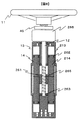
また、本実施例で用いる油量比率調整機構29は図4の構成に代えて図5に示す構成とすることもできる。油量比調整機構29のシリンダ30のピストン33は後述するボールナット91を挟み込んだ一対のピストン33a,33bによって構成されている。各ピストン33a,33bの外周にはシリンダ30との隙間をシールするシールリング92が取り付けられ、同じく内周にも調整軸35との隙間をシールするシールリング92が取り付けられている。また、上部と下部の調整軸35とシリンダ30との間にはボールベアリング93が設けられ、調整軸35を回転可能に支持する。さらに、調整軸35が貫通するシリンダ30の液密性を確保するために調整軸35の回転を許容しつつシリンダ30との隙間をシールするシールリング94が取り付けられている。
Further, the oil amount
ボールナット91と調整軸30にはらせん状に溝を形成し、そこに複数個のボール95を配置することでボールねじ機構を構成する。このボールねじ機構を用いることでボールナット91と接続されたピストン33が調整軸35の回転により軸方向へ滑らかに移動する。また、モータ36のモータ出力軸96にギヤを取り付け調整軸35の片側に備え付けられたギヤ97と噛合わせる。モータ出力軸96はハウジング98に取り付けられたボールベアリング93により回転可能に支持される。この構成によりモータ36の回転運動をピストン33の直動運動へ変換し、第5油圧室31と第6油圧室32に流入,流出する作動油の量を調整することで第1,第2油圧回路の油量比率を調整することができる。
A ball screw mechanism is configured by forming a spiral groove in the
また、油量比率調整機構29は油圧配管を介してステアリングホイール11と離れた場所に接続することにより、油圧減衰を利用して油量比率調整機構29の作動による振動が伝わらないようにすることもできる。
Further, the oil amount
また、先に示した構成では出力シリンダ23はパワーシリンダ22と平行に配置したが、車両の横幅が十分にある場合には、転舵軸20上にパワーシリンダ22と出力シリンダ23を直列に並べる構成とすることもできる。
Further, in the configuration described above, the
また、本実施例のステアリング装置10では、油量比率調整機構29と転舵アクチュエータ21のポンプ,モータなどを同じ位置に配置することもできるので、搭載性を確保することもできる。
Further, in the
また、本実施例のステアリング装置10では転舵アクチュエータ21としてパワーシリンダ22を利用した油圧式のものを用いているが、これに代えて図6に示すようにモータ100の回転をピニオン101により転舵軸20に形成したラックギヤ102を介して伝達するモータ式の転舵アクチュエータ21を用いることとしても前述と同様の制御を行うことで同様の作用効果を得ることができる。
Further, in the
本発明の第2の実施例を図7〜図9に基づいて詳細に説明する。以下、第1実施例と異なる構成に関してのみ説明し、第1実施例と同様の構成に関しては同一符号を付して重複した説明は省略する。 A second embodiment of the present invention will be described in detail with reference to FIGS. Hereinafter, only the configuration different from that of the first embodiment will be described, and the same configuration as that of the first embodiment is denoted by the same reference numerals, and redundant description is omitted.
このステアリング装置は、第1実施例に記載の第1油圧回路,第2油圧回路に加え、同様の構成の第3油圧回路,第4油圧回路を有することで構成される。 This steering apparatus is configured by having a third hydraulic circuit and a fourth hydraulic circuit having the same configuration in addition to the first hydraulic circuit and the second hydraulic circuit described in the first embodiment.
ステアリングホイール11と入力軸12を介して第二の入力シリンダ213が接続されている。第二の入力シリンダ213はピストン214によって、第9油圧室215と第
10油圧室216に液密に区画されている。ステアリングホイール11の回転運動は伝達機構217によってピストン214の直動運動に変換される。
A
また、転舵軸20と平行に第二の出力シリンダ223が設けられる。第二の出力シリンダ223は内部に転舵軸20と結合したピストン224があり、これによって第11油圧室225と第12油圧室226に液密に区画されている。第二の入力シリンダ213の第9油圧室215と第二の出力シリンダ223の第11油圧室225は第3油路227によって、第二の入力シリンダ213の第10油圧室216と第二の出力シリンダ223の第12油圧室226は第4油路228によってそれぞれ接続される。また、油量比率調整機構29の第二のシリンダ230が第9油圧室215と第11油圧室225と第3油路227とで構成される第3油圧回路と第10油圧室216と第12油圧室226と第4油路228
とで構成される第4油圧回路に接続され、第3油圧回路と第4油圧回路の作動油を行き来させることで第二の入力シリンダ213と第二の出力シリンダ223との間を移動する作動油量比率を調整する。ここで、油量比率調整機構29の第二のシリンダ230はシリンダ230を第7油圧室231と第8油圧室232に区画するピストン233を有し、変換ギヤ234と調整軸35とを介してモータ36と接続される。
A
Is operated to move between the
上記のような構成のステアリング装置10における2つの入力シリンダ13,213のピストン14と214は同じ動きをする。また、出力シリンダ23,223のピストン
24と224、油量比率調整機構29の2つのピストン33と233もそれぞれ同じ動きをする。これによって第1と第3油圧回路,第2と第4油圧回路にはそれぞれ同じ向きに同じ量の作動油が移動することになる。そのため、第1と第2油圧回路あるいは第3と第4油圧回路のいずれかに損傷を受け機能を果たさなくなった場合にも他方により操舵を継続することができるため、ステアリング装置の信頼性を十分に確保することができる2重系の油圧回路を構成となる。
The
通常操舵時,操舵伝達比設定時,中立位置補正時の各部の動作は先の実施例1で示したものと同様にすることでこのような2重系の油圧回路でも実施例1と同様の作用効果を得ることができる。 The operation of each part at the time of normal steering, setting of the steering transmission ratio, and correction of the neutral position is the same as that shown in the first embodiment, so that such a double hydraulic circuit is the same as that in the first embodiment. An effect can be obtained.
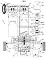
また、本実施例で用いる入力シリンダユニットは図8の概略図に示す構成とすることによって上記効果を得ることができる。入力シリンダ13,213には前述のように入力軸12を介してステアリングホイール11が接続される。入力シリンダ13,213を4つの独立した油圧室に区画するピストン14,214は後述するボールナット261に固定される。ピストン14,214の両端の外周にはシールリング262が取り付けられ、入力シリンダ13,213との間の隙間をシールする。
In addition, the input cylinder unit used in this embodiment can obtain the above-described effect by adopting the configuration shown in the schematic diagram of FIG. The
ボールナット261と入力軸12にはらせん状に溝を形成し、そこに複数個のボール
265を配置することでボールねじ機構を構成する。このボールねじ機構によりボールナット61と接続されたピストン14,214が入力軸12の回転により軸方向へ移動する。また、入力軸12はボールベアリング263によって入力シリンダ13,213のハウジングに回転可能に固定される。また、ステアリングホイール11の回転軸と入力軸の間に所定の増速比のギヤ266を設け、ピストン14,214のストロークを確保するような構成としてもよい。
The
この構成により入力シリンダ13,213の各油圧室の容積を変化させ、油路に作動油の流れを作り出す。また、同時に転舵輪18に加わる力により生成された油圧力が各油圧室に伝えられ、ピストン14,214に加わる圧力が変化することでステアリングホイールに反力が伝達される。
With this configuration, the volume of each hydraulic chamber of the
また、図2の入力シリンダ13と同様にボールナット261と入力軸12の溝の形状により、入力軸12の回転運動からピストン14,214の直動運動への伝達効率に比べ、ピストン14,214の直動運動から入力軸12の回転運動への伝達効率が低くなるように調整する。さらに、これに加えて、シリンダの圧力が高くなりピストン14,214に大きな力が加わる場合に変換効率をさらに低下させるように溝やボールの形状を調整しても良い。これにより、転舵アクチュエータ21が失陥時に油量比率調整機構29により転舵力をアシストする際にもステアリングホイールが大きな力で勝手に回転することがないようにできる。
2, the shape of the groove of the
また、本実施例の油量比率調整機構29は図9のような構成とすることで、上記効果を実現することができる。シリンダ30,230はラックギヤを形成したピストン33,
233によって二対の油圧室を区画する。このピストン33,233の両端にはシールリング270が取り付けられ、シリンダ30,230とピストン33,233の隙間をシールすることで液密性を確保する。ピストン30,230上のラックギヤはピニオンギヤ
271を挟み込むように噛合わせられる。また、ピニオンギヤ271は同軸にウォームホイール272が設けられ、モータ236のモータ出力軸にウォーム273を設けウォームホイール272とウォームギヤ機構を構成する。またモータ出力軸はハウジング274に取り付けられたボールベアリング275により回転可能に支持される。これによりモータ236の回転運動をピストン33,233の直動運動へ変換し、第5油圧室31と第6油圧室32,第7油圧室231と第8油圧室232に流入,流出する作動油の量を調整することで第1,第2油圧回路と第3,第4油圧回路の油量比率を調整することができる。
Moreover, the oil amount
Two pairs of hydraulic chambers are partitioned by 233. Seal rings 270 are attached to both ends of the
さらに、この油量比率調整機構29内に第5油圧室と第7油圧室とを結合するバランス油路276を第6油圧室と第8油圧室を結合するバランス油路277を設け、その途中にフリーピストン278,279を持つシリンダ280,281を形成する。フリーピストン278,279の外周にはシールリングが取り付けられ、シリンダ280,281との隙間をシールするため、第5油圧室と第7油圧室あるいは第6油圧室と第8油圧室の作動油が混ざり合うことはない。この構成によって、転舵軸18に同じ方向の力を加える第1と第3油圧回路あるいは第2と第4油圧回路でどちらか一方に微量の油漏れが生じた場合に、フリーピストン278,279の内、作動油の少ないほうへ移動し各油圧回路の総油量のバランスをとることができる。これによって同じ方向の力を伝達する2油圧回路間で同じ力を伝達することが可能となる。
Further, a balance oil passage 276 for connecting the fifth hydraulic chamber and the seventh hydraulic chamber is provided in the oil amount
また、本実施例の油圧回路を2重とすることで高い信頼性を確保する構成の転舵アクチュエータは、図7で示したパワーシリンダ22とポンプ40によって構成されたものに代えて、実施例1でしめした図6の転舵アクチュエータ21のようにモータ100とピニオン101,ラック102で構成しても同等の作用効果が得られる。
Further, the steering actuator configured to ensure high reliability by duplexing the hydraulic circuit of the present embodiment is replaced with the one constituted by the
10 ステアリング装置
11 ステアリングホイール
12 入力軸
13 入力シリンダ
14 ピストン
15 第1油圧室
16 第2油圧室
17 伝達機構
18 転舵輪
20 転舵軸
21 転舵アクチュエータ
22 パワーシリンダ
23 出力シリンダ
24 ピストン
25 第3油圧室
26 第4油圧室
27 第1油路
28 第2油路
29 油量比率調整機構
34 伝達機構
36,43 モータ
40 ポンプ
45 センサ
46 コントローラ
47 ストロークセンサ
50 一方向弁
51 圧力センサ
52 車両センサ入力
214 第二入力シリンダ
223 第二出力シリンダ
DESCRIPTION OF
Claims (20)
ステアリングホイールの回転運動を前記入力シリンダの軸方向運動に変換し伝達する際
の効率に比べ、前記入力シリンダ側からステアリングホイール側への運動に変換し伝達す
る際の効率の方が低い伝達機構と、
転舵輪に接続され、第3油圧室及び第4油圧室を有する出力シリンダと、
前記第1油圧室と前記第3油圧室とを接続する第1油路と、
前記第2油圧室と前記第4油圧室とを接続する第2油路と、
前記第1油圧室,第3油圧室及び第1油路を含んで構成される第1油圧回路に接続される第5油圧室と、前記第2油圧室,第4油圧室及び第2油路を含んで構成される第2油圧回路に接続される第6油圧室とを備え、これら第5油圧室と第6油圧室との容積比率をアクチュエータで調整することにより、前記第1油圧回路と前記第2油圧回路との油量比率を調整する油量比率調整機構と、
前記転舵輪に操舵アシスト力を付与する転舵アクチュエータと、
前記転舵アクチュエータの動作による前記第1油路と前記第2油路とを移動する作動油の増加分を吸収するように前記油量比率調整機構を制御し、
前記油量比率調整機構と前記転舵アクチュエータとを連携制御する制御回路と、
を備えたことを特徴とするステアリング装置。 An input cylinder having a first hydraulic chamber and a second hydraulic chamber;
A transmission mechanism having a lower efficiency in converting and transmitting the motion from the input cylinder side to the steering wheel side than the efficiency in converting the rotational motion of the steering wheel into the axial motion of the input cylinder and transmitting it; ,
An output cylinder connected to the steered wheels and having a third hydraulic chamber and a fourth hydraulic chamber;
A first oil passage connecting the first hydraulic chamber and the third hydraulic chamber;
A second oil passage connecting the second hydraulic chamber and the fourth hydraulic chamber;
A fifth hydraulic chamber connected to a first hydraulic circuit configured to include the first hydraulic chamber, the third hydraulic chamber, and the first oil passage; the second hydraulic chamber, the fourth hydraulic chamber, and the second oil passage; A sixth hydraulic chamber connected to a second hydraulic circuit including the first hydraulic circuit by adjusting a volume ratio of the fifth hydraulic chamber and the sixth hydraulic chamber with an actuator. An oil amount ratio adjusting mechanism for adjusting an oil amount ratio with the second hydraulic circuit ;
A steering actuator for applying a steering assist force to the steered wheels;
Controlling the oil amount ratio adjusting mechanism so as to absorb the increased amount of hydraulic oil moving between the first oil passage and the second oil passage due to the operation of the steering actuator;
A control circuit for cooperatively controlling the oil amount ratio adjusting mechanism and the steering actuator;
A steering apparatus comprising:
出する異常検出回路を備えたことを特徴とするステアリング装置。 The steering apparatus according to claim 1, further comprising an abnormality detection circuit that detects an operational abnormality of the steering actuator.
回路が異常を検出したとき、前記出力シリンダの液圧を制御することにより転舵輪に操舵
アシスト力を付与することを特徴とするステアリング装置。 3. The steering apparatus according to claim 2, wherein the oil amount ratio adjusting mechanism applies a steering assist force to the steered wheels by controlling a hydraulic pressure of the output cylinder when the abnormality detection circuit detects an abnormality. A steering apparatus characterized by the above.
ーブと、このシリンダチューブを前記第1油圧回路に接続された第5油圧室と前記第2油
圧回路に接続された第6油圧室とに区画するピストンと、電動モータと、この電動モータ
の回転方向の運動を前記ピストンの軸方向運動へ変換する変換ギヤとを備えて構成され、
前記変換ギヤは、前記ピストン側から前記電動モータ側への力の伝達を抑制する非可逆性
を有することを特徴とするステアリング装置。 3. The steering device according to claim 2, wherein the oil amount ratio adjusting mechanism includes a cylinder tube, a fifth hydraulic chamber in which the cylinder tube is connected to the first hydraulic circuit, and a second hydraulic circuit that is connected to the second hydraulic circuit. Comprising a piston partitioned into six hydraulic chambers, an electric motor, and a conversion gear for converting the movement of the electric motor in the rotational direction into the axial movement of the piston,
The steering device according to claim 1, wherein the conversion gear has irreversibility that suppresses transmission of force from the piston side to the electric motor side.
ホイールと転舵輪との間に中立位置のずれが生じた場合に、前記転舵アクチュエータと連
携してこのずれを補正することを特徴とするステアリング装置。 2. The steering device according to claim 1, wherein the oil amount ratio adjusting mechanism corrects the deviation in cooperation with the steering actuator when a neutral position deviation occurs between the steering wheel and the steered wheel. 3. A steering device characterized by that.
る操舵角センサと、転舵輪の転舵角を検出する転舵角センサと、を更に備え、前記油量比
率調整機構は、前記操舵角センサと前記転舵角センサのセンサ出力に基づき前記中立位置
のずれを補正することを特徴とするステアリング装置。 The steering apparatus according to claim 5, further comprising: a steering angle sensor that detects a steering angle of a steering wheel; and a turning angle sensor that detects a turning angle of a steered wheel, wherein the oil amount ratio adjusting mechanism includes: A steering apparatus, wherein the neutral position shift is corrected based on sensor outputs of the steering angle sensor and the steering angle sensor.
続され、1対の油圧室を有するパワーシリンダと、電動モータによって正逆回転駆動され
、前記パワーシリンダに選択的に液圧を供給する正逆回転ポンプとを備えて構成されるこ
とを特徴とするステアリング装置。 2. The steering device according to claim 1, wherein the steering actuator is connected to the steered wheels and is driven to rotate forward and backward by an electric motor having a pair of hydraulic chambers and an electric motor. A steering apparatus comprising: a forward / reverse rotating pump for supplying pressure.
とは互いに並列に配置されることを特徴とするステアリング装置。 8. The steering apparatus according to claim 7, wherein the output cylinder and the power cylinder are arranged in parallel to each other.
第1油圧回路とを接続する第1接続通路と、この第1接続通路に設けられ、前記リザーバ
タンク側から前記第1油圧回路側への油の流れのみを許容する第1一方向弁と、前記リザ
ーバタンクと前記第2油圧回路とを接続する第2接続通路と、この第2接続通路に設けら
れ、前記リザーバタンクから前記第2油圧回路側への油の流れのみを許容する第2一方向
弁と、を更に有することを特徴とするステアリング装置。 The steering device according to claim 1 is provided in a reservoir tank, a first connection passage that connects the reservoir tank and the first hydraulic circuit, and the first connection passage, and the first tank is provided from the reservoir tank side. A first one-way valve that allows only oil flow to the hydraulic circuit side; a second connection passage that connects the reservoir tank and the second hydraulic circuit; and the reservoir tank provided in the second connection passage. And a second one-way valve that allows only the flow of oil from the second hydraulic circuit side to the second hydraulic circuit side.
出する液圧センサを更に備え、前記制御回路は前記液圧センサのセンサ出力に基づき前記
転舵アクチュエータを制御することを特徴とするステアリング装置。 The steering apparatus according to claim 1, further comprising a hydraulic pressure sensor that detects hydraulic pressures of the first hydraulic chamber and the second hydraulic chamber, and the control circuit performs the steering based on a sensor output of the hydraulic pressure sensor. A steering device that controls an actuator.
のセンサ出力に基づき、前記第1油圧回路及び前記第2油圧回路の異常を検出することを
特徴とするステアリング装置。 11. The steering apparatus according to claim 10, wherein the abnormality detection circuit detects an abnormality in the first hydraulic circuit and the second hydraulic circuit based on a sensor output of the hydraulic pressure sensor.
記第2油圧室の圧力が高いほど前記入力シリンダ側から前記ステアリングホイールへの伝
達効率が低くなることを特徴とするステアリング装置。 2. The steering device according to claim 1, wherein the transmission mechanism has a lower transmission efficiency from the input cylinder side to the steering wheel as a pressure in the first hydraulic chamber or the second hydraulic chamber is higher. Steering device.
ステアリングホイールの回転運動を前記入力シリンダの軸方向運動に変換し伝達する際
の効率に比べ、前記入力シリンダ側からステアリングホイール側への運動に変換し伝達す
る際の効率の方が低い伝達機構と、
転舵輪に接続され、第3油圧室及び第4油圧室を有する出力シリンダと、
前記第1油圧室と前記第3油圧室とを接続する第1油路と、
前記第2油圧室と前記第4油圧室とを接続する第2油路と、
前記転舵輪に操舵アシスト力を付与する転舵アクチュエータと、
前記第1油圧室,第3油圧室及び第1油路を含んで構成される第1油圧回路に接続される第5油圧室と、前記第2油圧室,第4油圧室及び第2油路を含んで構成される第2油圧回路に接続される第6油圧室とを備え、これら第5油圧室と第6油圧室との容積比率をアクチュエータで調整することにより、前記第1油圧回路と前記第2油圧回路との油量比率を調整する油量比率調整機構と、前記ステアリングホイールの操作量に対する前記転舵アクチュエータの動作量の不一致を補正するように前記油量比率調整機構と前記転舵アクチュエータとを連携制御する制御回路と、
を有することを特徴とするステアリング装置。 An input cylinder having a first hydraulic chamber and a second hydraulic chamber;
A transmission mechanism having a lower efficiency in converting and transmitting the motion from the input cylinder side to the steering wheel side than the efficiency in converting the rotational motion of the steering wheel into the axial motion of the input cylinder and transmitting it; ,
An output cylinder connected to the steered wheels and having a third hydraulic chamber and a fourth hydraulic chamber;
A first oil passage connecting the first hydraulic chamber and the third hydraulic chamber;
A second oil passage connecting the second hydraulic chamber and the fourth hydraulic chamber;
A steering actuator for applying a steering assist force to the steered wheels;
A fifth hydraulic chamber connected to a first hydraulic circuit configured to include the first hydraulic chamber, the third hydraulic chamber, and the first oil passage; the second hydraulic chamber, the fourth hydraulic chamber, and the second oil passage; A sixth hydraulic chamber connected to a second hydraulic circuit including the first hydraulic circuit by adjusting a volume ratio of the fifth hydraulic chamber and the sixth hydraulic chamber with an actuator. An oil amount ratio adjusting mechanism that adjusts an oil amount ratio with the second hydraulic circuit, and the oil amount ratio adjusting mechanism and the rolling device so as to correct the mismatch of the operation amount of the steering actuator with respect to the operation amount of the steering wheel. A control circuit for cooperatively controlling the rudder actuator;
A steering apparatus comprising:
タの動作量に応じて駆動制御されることを特徴とするステアリング装置。 14. The steering apparatus according to claim 13, wherein the correction mechanism is driven and controlled in accordance with an operation amount of the steering actuator.
と転舵輪との間に中立位置のずれが生じた場合には、このずれを補正することを特徴とす
るステアリング装置。 14. The steering apparatus according to claim 13, wherein when the neutral position shift occurs between the steering wheel and the steered wheel, the correction mechanism corrects the shift.
ステアリングホイールの回転運動を前記入力シリンダの軸方向運動に変換し伝達するボ
ールねじ機構と、
転舵輪に接続され、第3油圧室及び第4油圧室を有する出力シリンダと、
前記第1油圧室と前記第3油圧室とを接続する第1油路と、
前記第2油圧室と前記第4油圧室とを接続する第2油路と、
前記第1油圧室,第3油圧室及び第1油路を含んで構成される第1油圧回路に接続され
る第5油圧室と、前記第2油圧室,第4油圧室及び第2油路を含んで構成される第2油圧
回路に接続される第6油圧室とを備え、これら第5油圧室と第6油圧室との容積比率をアクチュエータで調整することにより、前記第1油圧回路と前記第2油圧回路との油量比率を調整する油量比率調整機構と、
前記転舵輪に操舵アシスト力を付与する転舵アクチュエータと、
前記転舵アクチュエータの動作による前記第1油路と前記第2油路とを移動する作動油の増加分を吸収するように前記油量比率調整機構を制御し、
前記油量比率調整機構と前記転舵アクチュエータとを連携制御する制御回路と、
を備えたことを特徴とするステアリング装置。 An input cylinder having a first hydraulic chamber and a second hydraulic chamber;
A ball screw mechanism that converts and transmits the rotational motion of the steering wheel into the axial motion of the input cylinder;
An output cylinder connected to the steered wheels and having a third hydraulic chamber and a fourth hydraulic chamber;
A first oil passage connecting the first hydraulic chamber and the third hydraulic chamber;
A second oil passage connecting the second hydraulic chamber and the fourth hydraulic chamber;
A fifth hydraulic chamber connected to a first hydraulic circuit configured to include the first hydraulic chamber, the third hydraulic chamber, and the first oil passage; the second hydraulic chamber, the fourth hydraulic chamber, and the second oil passage; A sixth hydraulic chamber connected to a second hydraulic circuit including the first hydraulic circuit by adjusting a volume ratio of the fifth hydraulic chamber and the sixth hydraulic chamber with an actuator. An oil amount ratio adjusting mechanism for adjusting an oil amount ratio with the second hydraulic circuit;
A steering actuator for applying a steering assist force to the steered wheels;
Controlling the oil amount ratio adjusting mechanism so as to absorb the increased amount of hydraulic oil that moves in the first oil passage and the second oil passage due to the operation of the steering actuator;
A control circuit for cooperatively controlling the oil amount ratio adjusting mechanism and the steering actuator;
A steering apparatus comprising:
チュエータとは隣接配置されることを特徴とするステアリング装置。 The steering device according to claim 16, wherein the oil amount ratio adjusting mechanism and the turning actuator are disposed adjacent to each other.
機構に接続された第2入力シリンダと、転舵輪に接続され、1対の油圧室を有する第2出
力シリンダと、前記第2入力シリンダと前記第2出力シリンダの夫々の油圧室同士が接続
されることにより構成される第3油圧回路及び第4油圧回路に夫々接続される第7油圧室
及び第8油圧室を更に備え、前記油量比率調整機構は前記第5油圧室と前記第6油圧室と
の容積比率の調整及び前記第7油圧室と前記第8油圧室との容積比率の調整を行うことを
特徴とするステアリング装置。 17. The steering apparatus according to claim 16, comprising a pair of hydraulic chambers, a second input cylinder connected to the ball screw mechanism, and a second output cylinder connected to the steered wheels and having a pair of hydraulic chambers. And a seventh hydraulic chamber and an eighth hydraulic pressure respectively connected to a third hydraulic circuit and a fourth hydraulic circuit configured by connecting respective hydraulic chambers of the second input cylinder and the second output cylinder. And an oil volume ratio adjusting mechanism that adjusts the volume ratio between the fifth hydraulic chamber and the sixth hydraulic chamber and the volume ratio between the seventh hydraulic chamber and the eighth hydraulic chamber. A steering apparatus characterized by the above.
とを接続する第1バランス油路と、この第1バランス油路に設けられた第1フリーピスト
ンと、前記第2油圧回路と前記第4油圧回路とを接続する第2バランス油路と、この第2
バランス油路に設けられた第2フリーピストンと、を更に有することを特徴とするステア
リング装置。 The steering apparatus according to claim 18, wherein a first balance oil passage connecting the first hydraulic circuit and the third hydraulic circuit, a first free piston provided in the first balance oil passage, and the first A second balance oil passage connecting the second hydraulic circuit and the fourth hydraulic circuit, and the second
And a second free piston provided in the balance oil passage.
フリーピストンは前記油量比率調整機構内部に設けられることを特徴とするステアリング
装置。 The steering device according to claim 19, wherein the first free piston and the second free piston.
A steering device, wherein a free piston is provided inside the oil amount ratio adjusting mechanism.
Priority Applications (5)
| Application Number | Priority Date | Filing Date | Title |
|---|---|---|---|
| JP2006279401A JP4902309B2 (en) | 2006-10-13 | 2006-10-13 | Steering device |
| US11/870,956 US8066091B2 (en) | 2006-10-13 | 2007-10-11 | Steering system |
| CNA2007101807450A CN101161532A (en) | 2006-10-13 | 2007-10-11 | Steering system |
| DE602007012976T DE602007012976D1 (en) | 2006-10-13 | 2007-10-12 | steering system |
| EP07020077A EP1911659B1 (en) | 2006-10-13 | 2007-10-12 | Steering system |
Applications Claiming Priority (1)
| Application Number | Priority Date | Filing Date | Title |
|---|---|---|---|
| JP2006279401A JP4902309B2 (en) | 2006-10-13 | 2006-10-13 | Steering device |
Publications (2)
| Publication Number | Publication Date |
|---|---|
| JP2008094288A JP2008094288A (en) | 2008-04-24 |
| JP4902309B2 true JP4902309B2 (en) | 2012-03-21 |
Family
ID=38920650
Family Applications (1)
| Application Number | Title | Priority Date | Filing Date |
|---|---|---|---|
| JP2006279401A Expired - Fee Related JP4902309B2 (en) | 2006-10-13 | 2006-10-13 | Steering device |
Country Status (5)
| Country | Link |
|---|---|
| US (1) | US8066091B2 (en) |
| EP (1) | EP1911659B1 (en) |
| JP (1) | JP4902309B2 (en) |
| CN (1) | CN101161532A (en) |
| DE (1) | DE602007012976D1 (en) |
Families Citing this family (39)
| Publication number | Priority date | Publication date | Assignee | Title |
|---|---|---|---|---|
| DE102008031213A1 (en) * | 2008-07-03 | 2010-06-10 | Rheinmetall Landsysteme Gmbh | Steering device for a wheeled vehicle with axle steering |
| FR2935670B1 (en) * | 2008-09-11 | 2011-08-05 | Jtekt Hpi | METHOD OF STRATEGY FOR REDUCING THE ENERGY CONSUMPTION OF A MOTOR VEHICLE |
| GB2464728A (en) * | 2008-10-27 | 2010-04-28 | Agco Gmbh | Hydraulic steering device with redundancy |
| JP2010143242A (en) * | 2008-12-16 | 2010-07-01 | Hitachi Automotive Systems Ltd | Steering control device |
| JP2010143240A (en) * | 2008-12-16 | 2010-07-01 | Hitachi Automotive Systems Ltd | Steering control device |
| IT1392732B1 (en) * | 2009-01-27 | 2012-03-16 | Palmarix Ltd | SYSTEM FOR CONTROL OF THE DRIVING OF A VEHICLE. |
| DE102009018976A1 (en) | 2009-04-25 | 2010-10-28 | Bayerische Motoren Werke Aktiengesellschaft | Vehicle steering system of the by-wire design |
| DE102009059677A1 (en) * | 2009-12-19 | 2011-06-22 | HYDAC System GmbH, 66280 | Hydraulic steering |
| JP5276088B2 (en) * | 2010-12-24 | 2013-08-28 | 日立オートモティブシステムズステアリング株式会社 | Power steering device |
| CN102121491A (en) * | 2011-04-15 | 2011-07-13 | 厦门大学 | Hydraulic cylinder with position sensing device |
| JP2013099986A (en) * | 2011-11-07 | 2013-05-23 | Jtekt Corp | Vehicle steering device |
| JP2013103616A (en) * | 2011-11-14 | 2013-05-30 | Jtekt Corp | Power steering device |
| US9428209B2 (en) * | 2011-12-21 | 2016-08-30 | Toyota Jidosha Kabushiki Kaisha | Steering device |
| KR20130090527A (en) * | 2012-02-06 | 2013-08-14 | 주식회사 만도 | Hybrid power steering apparatus |
| JP6115757B2 (en) * | 2012-02-17 | 2017-04-19 | 株式会社ジェイテクト | Vehicle steering system |
| EP2631154A3 (en) * | 2012-02-27 | 2016-03-23 | Schaeffler Technologies AG & Co. KG | Device for transmitting a haptically perceivable signal to a steering shaft of a vehicle |
| CN102862604B (en) * | 2012-09-18 | 2015-08-05 | 重庆迪马工业有限责任公司 | Double-front axle ladder vehicle all hydraulic pressure steering-gear |
| WO2014096893A1 (en) * | 2012-12-18 | 2014-06-26 | Renault Trucks | A power steering system for a vehicle |
| US20140246264A1 (en) * | 2013-03-04 | 2014-09-04 | Mark L. Alderson | Full hydraulic power steering with positive force feedback |
| GB2516447B (en) * | 2013-07-22 | 2016-06-15 | Jc Bamford Excavators Ltd | A Steering Arrangement |
| KR101509927B1 (en) * | 2013-09-24 | 2015-04-07 | 현대자동차주식회사 | Steer by wire system |
| EP3104993B1 (en) * | 2014-02-14 | 2019-09-11 | Danieli & C. Officine Meccaniche S.p.A. | Control device for oscillating table |
| CN103963834A (en) * | 2014-05-20 | 2014-08-06 | 盐城振宇科技发展有限公司 | Electro-hydraulic power steering mechanism for cars |
| CN104228939B (en) * | 2014-06-13 | 2017-10-20 | 王洁梅 | A kind of oil piping system of automobile steering device |
| KR102108926B1 (en) * | 2014-07-29 | 2020-05-13 | 현대자동차(주) | Steer by wire system |
| CN104085446B (en) * | 2014-07-30 | 2016-10-05 | 中联重科股份有限公司 | Vehicle and wheel steering system thereof |
| KR102183950B1 (en) * | 2014-09-29 | 2020-11-30 | 현대모비스 주식회사 | Motor control method dual mpu hydraulic circuit system |
| CN105235741B (en) * | 2015-11-11 | 2018-05-04 | 吉林大学 | A kind of variable automobile gearratio steering based on hydraulic system |
| KR101813385B1 (en) * | 2016-06-20 | 2017-12-28 | 임관순 | Vehicle steering apparatus using hydraulic pressure |
| US9975573B2 (en) * | 2016-07-29 | 2018-05-22 | Ford Global Technologies, Llc | Enhanced steering operation |
| KR20190028949A (en) * | 2017-09-11 | 2019-03-20 | 주식회사 만도 | Rear Wheel Steering System and Controlling Method Thereof |
| DE102017122235A1 (en) * | 2017-09-26 | 2019-03-28 | Weber-Hydraulik Gmbh | Hydraulic power unit, method for operating a hydraulic power unit and steering system |
| CN107901979B (en) * | 2017-11-10 | 2020-02-28 | 南京双环电器股份有限公司 | Automobile electro-hydraulic active steering road feel control system and control method thereof |
| CN108644176B (en) * | 2018-04-02 | 2019-05-28 | 李�一 | A kind of heavy-duty autonomous operation vehicle high-precision steering driving hydraulic cylinder |
| JP7091949B2 (en) * | 2018-08-30 | 2022-06-28 | トヨタ自動車株式会社 | Vehicle control unit |
| CN111186479B (en) * | 2020-01-15 | 2021-07-20 | 江苏大学 | Fault-tolerant system and method for wire-controlled steering |
| CN112654931B (en) * | 2020-08-31 | 2022-05-13 | 华为技术有限公司 | Control system, control method, intelligent automobile and device |
| CN117813232A (en) * | 2022-01-25 | 2024-04-02 | 华为技术有限公司 | Steering hand feeling simulation booster, steering system and control method |
| CN117719591A (en) * | 2024-02-08 | 2024-03-19 | 杭州世宝汽车方向机有限公司 | Hydraulic mechanical backup system suitable for steer-by-wire device and control method |
Family Cites Families (12)
| Publication number | Priority date | Publication date | Assignee | Title |
|---|---|---|---|---|
| DE19522057C1 (en) | 1994-07-11 | 1996-09-19 | Wolfgang Gabriel | Hydraulic steering device |
| DE19842627A1 (en) | 1998-09-17 | 2000-04-06 | Daimler Chrysler Ag | Steering system for a vehicle |
| JP2972765B1 (en) | 1998-11-20 | 1999-11-08 | 静岡日本電気株式会社 | Method and system for carrier sensing on mobile station side of simplified portable telephone system |
| DE19859806B4 (en) * | 1998-12-23 | 2005-03-31 | Daimlerchrysler Ag | Steering system for motor vehicles |
| JP3536296B2 (en) | 1999-01-22 | 2004-06-07 | トヨタ自動車株式会社 | Vehicle steering control device |
| JP2000211641A (en) | 1999-01-26 | 2000-08-02 | Jido Hanbai Shuppansha:Kk | Can for beverage such as juice |
| DE29915179U1 (en) * | 1999-08-30 | 2000-01-05 | Trw Fahrwerksyst Gmbh & Co | Steering system for a vehicle |
| JP2002029430A (en) * | 2000-07-13 | 2002-01-29 | Koyo Seiko Co Ltd | Steering system for vehicle |
| JP2003261055A (en) * | 2002-03-12 | 2003-09-16 | Toyota Motor Corp | Steering apparatus for vehicle |
| JP2003276617A (en) | 2002-03-25 | 2003-10-02 | Honda Motor Co Ltd | Cable type steering device |
| JP2005082007A (en) | 2003-09-09 | 2005-03-31 | Hitachi Unisia Automotive Ltd | Power steering device |
| DE10344662A1 (en) | 2003-09-25 | 2005-05-04 | Cuadro Diogenes Perez | Hydraulic steering system for motor vehicle has regulating pump for high frequency intermittent transport operation as hydraulic pressure source for operating servo motor in one or other direction |
-
2006
- 2006-10-13 JP JP2006279401A patent/JP4902309B2/en not_active Expired - Fee Related
-
2007
- 2007-10-11 CN CNA2007101807450A patent/CN101161532A/en active Pending
- 2007-10-11 US US11/870,956 patent/US8066091B2/en not_active Expired - Fee Related
- 2007-10-12 DE DE602007012976T patent/DE602007012976D1/en active Active
- 2007-10-12 EP EP07020077A patent/EP1911659B1/en not_active Expired - Fee Related
Also Published As
| Publication number | Publication date |
|---|---|
| JP2008094288A (en) | 2008-04-24 |
| US8066091B2 (en) | 2011-11-29 |
| US20090038876A1 (en) | 2009-02-12 |
| CN101161532A (en) | 2008-04-16 |
| EP1911659B1 (en) | 2011-03-09 |
| EP1911659A2 (en) | 2008-04-16 |
| EP1911659A3 (en) | 2010-01-20 |
| DE602007012976D1 (en) | 2011-04-21 |
Similar Documents
| Publication | Publication Date | Title |
|---|---|---|
| JP4902309B2 (en) | Steering device | |
| US10370028B2 (en) | Power steering device | |
| EP2199184B1 (en) | Steering control apparatus | |
| JP2014227042A (en) | Power steering device | |
| KR20130090527A (en) | Hybrid power steering apparatus | |
| JP2010143241A (en) | Steering control device | |
| US7665569B2 (en) | Power steering system | |
| JP2005518303A (en) | Hydraulic servo steering device | |
| CN101970277B (en) | Power steering device | |
| JP2015160447A (en) | power steering device | |
| EP3089906A1 (en) | Hydraulically assisted steering system for motor vehicles | |
| CN112623024B (en) | Steering system and engineering vehicle | |
| JP5964775B2 (en) | Power steering device | |
| JP2010137603A (en) | Power steering device | |
| KR101217321B1 (en) | Active Front Wheel Steering having Hydraulic Actuator | |
| JP2009280188A (en) | Electrohydraulic power steering device | |
| KR20110125778A (en) | Power assisting device for vehicle and power steering apparatus for vehicle having the same | |
| JP2007253653A (en) | Power steering device | |
| JP2005082007A (en) | Power steering device | |
| KR20120048296A (en) | Rattle noise reduction structure of mdps vehicle using oil pressure | |
| CN114872784A (en) | Differential speed variable transmission ratio device and method and automobile steering system applying same | |
| JP3277779B2 (en) | Steering gear | |
| JP2004092581A (en) | Hydraulic motor and controlling device provided with the same | |
| JP2007261506A (en) | Power steering device | |
| JP2008114759A (en) | Vehicle steering device |
Legal Events
| Date | Code | Title | Description |
|---|---|---|---|
| A621 | Written request for application examination |
Free format text: JAPANESE INTERMEDIATE CODE: A621 Effective date: 20081106 |
|
| A711 | Notification of change in applicant |
Free format text: JAPANESE INTERMEDIATE CODE: A712 Effective date: 20091214 |
|
| A521 | Request for written amendment filed |
Free format text: JAPANESE INTERMEDIATE CODE: A523 Effective date: 20091217 |
|
| A977 | Report on retrieval |
Free format text: JAPANESE INTERMEDIATE CODE: A971007 Effective date: 20110331 |
|
| A131 | Notification of reasons for refusal |
Free format text: JAPANESE INTERMEDIATE CODE: A131 Effective date: 20110719 |
|
| A521 | Request for written amendment filed |
Free format text: JAPANESE INTERMEDIATE CODE: A523 Effective date: 20110920 |
|
| TRDD | Decision of grant or rejection written | ||
| A01 | Written decision to grant a patent or to grant a registration (utility model) |
Free format text: JAPANESE INTERMEDIATE CODE: A01 Effective date: 20111206 |
|
| A01 | Written decision to grant a patent or to grant a registration (utility model) |
Free format text: JAPANESE INTERMEDIATE CODE: A01 |
|
| A61 | First payment of annual fees (during grant procedure) |
Free format text: JAPANESE INTERMEDIATE CODE: A61 Effective date: 20111228 |
|
| R150 | Certificate of patent or registration of utility model |
Ref document number: 4902309 Country of ref document: JP Free format text: JAPANESE INTERMEDIATE CODE: R150 Free format text: JAPANESE INTERMEDIATE CODE: R150 |
|
| FPAY | Renewal fee payment (event date is renewal date of database) |
Free format text: PAYMENT UNTIL: 20150113 Year of fee payment: 3 |
|
| LAPS | Cancellation because of no payment of annual fees |