JP4901360B2 - Key switch device and keyboard having key switch device - Google Patents
Key switch device and keyboard having key switch device Download PDFInfo
- Publication number
- JP4901360B2 JP4901360B2 JP2006220072A JP2006220072A JP4901360B2 JP 4901360 B2 JP4901360 B2 JP 4901360B2 JP 2006220072 A JP2006220072 A JP 2006220072A JP 2006220072 A JP2006220072 A JP 2006220072A JP 4901360 B2 JP4901360 B2 JP 4901360B2
- Authority
- JP
- Japan
- Prior art keywords
- switch device
- key top
- link member
- key
- key switch
- Prior art date
- Legal status (The legal status is an assumption and is not a legal conclusion. Google has not performed a legal analysis and makes no representation as to the accuracy of the status listed.)
- Expired - Fee Related
Links
Images


Classifications
-
- H—ELECTRICITY
- H01—ELECTRIC ELEMENTS
- H01H—ELECTRIC SWITCHES; RELAYS; SELECTORS; EMERGENCY PROTECTIVE DEVICES
- H01H3/00—Mechanisms for operating contacts
- H01H3/02—Operating parts, i.e. for operating driving mechanism by a mechanical force external to the switch
- H01H3/12—Push-buttons
- H01H3/122—Push-buttons with enlarged actuating area, e.g. of the elongated bar-type; Stabilising means therefor
- H01H3/125—Push-buttons with enlarged actuating area, e.g. of the elongated bar-type; Stabilising means therefor using a scissor mechanism as stabiliser
Description
本発明は、打鍵操作されるキースイッチ装置に関し、特に電子機器の入力装置であるキーボードで好適に使用されるキースイッチ装置に関する。更に本発明はそのようなキースイッチ装置を有するキーボードに関する。 The present invention relates to a key switch device that is operated to make a keystroke, and more particularly to a key switch device that is preferably used in a keyboard that is an input device of an electronic apparatus. The present invention further relates to a keyboard having such a key switch device.
従来、ノート型やパームトップ型のパーソナルコンピュータ等の携帯電子機器の分野では、機器の携帯性を向上させる目的で、キーボードを含む機器筐体の薄型化すなわち低背化を実現するための様々な技術が提案されている。特に、打鍵操作される多数のキースイッチを備えたキーボードを低背化する際には、一定水準の操作性を確保するためにキースイッチ装置のストローク量を所定量に維持しつつ、キースイッチ装置の非操作(スイッチオフ)時及び押し下げ操作(スイッチオン)時の全高を削減することが要求されている。 2. Description of the Related Art Conventionally, in the field of portable electronic devices such as notebook type and palmtop type personal computers, various devices for reducing the thickness of a device case including a keyboard, that is, reducing the height of the device case, are aimed at improving the portability of the device. Technology has been proposed. In particular, when reducing the height of a keyboard having a large number of key switches operated by keystrokes, the key switch device maintains the stroke amount of the key switch device at a predetermined amount in order to ensure a certain level of operability. It is required to reduce the overall height during non-operation (switch-off) and push-down operation (switch-on).
低背型キーボードに使用できるキースイッチ装置は一般に、ベースとベース上に配置されるキートップと、互いに連動してキートップをベース上で昇降方向へ案内支持する一対のリンク部材と、キートップの昇降動作に対応して電気回路の接点を開閉するスイッチ機構とを備えて構成される。一対のリンク部材としては、側面視逆V字状に組み合わされて、それらの第一端部領域でベースに摺動自在に係合し、かつ第二端部領域で、互いにギア部で歯車状にかみ合うとともにキートップに回転自在に連結される、いわゆるギアリンク形式のもの(例えば、特許文献1参照のこと)が採用されている。また、キースイッチの低背化及びストローク増加を目的としたギアリンク形式の新構造が提案されている(例えば、特許文献2参照のこと)。この方式は、ベースの板金部分に形成された立て板部を有し、立て板部の案内孔にリンク部材の摺動部が挿入されると共に、キートップが軸受部を有し、そこにリンク部材の回転部が軸支される構造となっている。 A key switch device that can be used for a low-profile keyboard generally includes a base, a key top disposed on the base, a pair of link members that guide and support the key top in the ascending / descending direction on the base, and a key top And a switch mechanism that opens and closes the contacts of the electric circuit in response to the lifting operation. The pair of link members are combined in an inverted V shape when viewed from the side, slidably engage with the base in the first end region, and in the second end region, mutually geared. A so-called gear link type (see, for example, Patent Document 1) that engages with the key top and is rotatably connected to the key top is employed. A new gear link type structure has been proposed for the purpose of reducing the height of the key switch and increasing the stroke (see, for example, Patent Document 2). This system has a standing plate portion formed in a sheet metal portion of a base, a sliding portion of a link member is inserted into a guide hole of the standing plate portion, and a key top has a bearing portion, and a link is provided there. The rotating part of the member is supported by the shaft.
前述した特許文献2のギアリンク方式では、キートップをリンク部材に取り付ける前に、リンク部材を保持しているのは、板金部材の4箇所の立て板部のみである。構造的には、立て板部がリンク部材を両方から挟み込むような形状になっているが、実際の動作に際し、立て板部とリンク部材との間にはある程度のクリアランスが必要なため、リンク部材は完全に立て板部によって押さえられている訳ではない。そこで、キートップを取り付ける際に不用意にリンク部材に触れたりすると、リンク部材同士が位置ずれを生じ、場合によってはギアの噛み合わせが外れたりすることがある。リンク部材同士がずれた状態でキートップを取り付けるとリンク部材に対し無理な力が加わり、最悪の場合リンク部材の摺動部がベースの立て板部の案内孔から外れるおそれがある。
In the gear link system of
また、作業者がキートップをリンク部材に取り付ける際に、最初に、キートップの片側に並ぶ一対の軸受部を、一対のリンク部材の対応側の回転部に係合させてから、次に、キートップの反対側の一対の軸受部を一対のリンク部材の対応側の回転部に係合させるような、構造上望ましくない取り付け方が行なわれる場合があった。前述した特許文献2のギアリンク方式では、このような、リンク部材を損傷するおそれがある望ましくないキートップ取り付け手法を、未然に防止することが困難であった。
Further, when the operator attaches the key top to the link member, first, after engaging the pair of bearing portions arranged on one side of the key top with the rotating portion on the corresponding side of the pair of link members, There has been a case in which an undesired attachment method is performed in which the pair of bearing portions on the opposite side of the key top are engaged with the rotating portions on the corresponding side of the pair of link members. In the gear link system of
本発明の目的は、キートップの案内支持材としてギアリンク方式の一対のリンク部材を有するキースイッチ装置において、キートップ取り付け時にリンク部材同士がずれない様な構造を有するキースイッチ装置を提供することである。 An object of the present invention is to provide a key switch device having a pair of gear link type link members as a guide support material for the key top, and having a structure that prevents the link members from being displaced when the key top is attached. It is.
本発明の他の目的は、一対のリンク部材が有する複数の回転部に対して、キートップの複数の軸受部をほぼ同時に取り付けるように、作業の自由度をある程度制限できる構造を有するキースイッチ装置を提供することである。 Another object of the present invention is to provide a key switch device having a structure capable of limiting the degree of freedom of work to some extent so that a plurality of bearing portions of a key top are attached almost simultaneously to a plurality of rotating portions of a pair of link members. Is to provide.
上記目的を達成するために、本発明によれば以下のような特徴を有するキースイッチ装置およびキーボードが提供される。
請求項1の発明では、ベースと、該ベース上に配置されるキートップと、互いに連動して該キートップを上記ベース上で昇降方向へ案内支持する一対のリンク部材と、上記キートップの昇降動作に対応して電気回路の接点を開閉するスイッチ機構とを有し、
上記一対のリンク部材は、相互に噛み合うギア部をそれぞれに有し、
上記一対のリンク部材の各々が、上記キートップに係合する回転部を有すると共に、上記キートップが、上記回転部に回転可能に係合する軸受部を有する、キースイッチ装置において、
上記キートップを一対の上記リンク部材に取り付ける際に生じ得る、それぞれの上記ギア部の相互の位置ずれを防止する位置ずれ防止機構を備え、
上記位置ずれ防止機構は、上記ベースに設けられる壁部であって、上記キートップを上記一対のリンク部材に取り付けるときに上記軸受部の案内になる壁部を有する、ことを特徴とする。
In order to achieve the above object, according to the present invention, a key switch device and a keyboard having the following features are provided.
According to the first aspect of the present invention, a base, a key top disposed on the base, a pair of link members that guide and support the key top in the up-and-down direction on the base in conjunction with each other, and the up and down of the key top A switch mechanism that opens and closes the contact of the electric circuit in response to the operation,
Each of the pair of link members has a gear portion that meshes with each other,
In the key switch device, each of the pair of link members has a rotating portion that engages with the key top, and the key top has a bearing portion that rotatably engages with the rotating portion.
A misalignment prevention mechanism for preventing misalignment of the gear portions, which may occur when the key top is attached to the pair of link members,
The misalignment prevention mechanism includes a wall portion provided on the base, the wall portion serving as a guide for the bearing portion when the key top is attached to the pair of link members .
請求項2の発明では、上記壁部は、上記リンク部材に対して上記スイッチ機構の上記接点とは反対側であって、上記リンク部材の上記回転部の外側の位置で、上記ベースに設けられる、ことを特徴とする。 According to a second aspect of the present invention, the wall portion is provided on the base at a position opposite to the contact point of the switch mechanism with respect to the link member and outside the rotating portion of the link member. that, characterized in that.
請求項3の発明では、上記壁部は、上記リンク部材に対して上記スイッチ機構の上記接点と同じ側であって、上記リンク部材の上記回転部の内側の位置で、上記ベースに設けられる、ことを特徴とする。
In the invention of
請求項4の発明では、上記壁部を上記ベースと一体的に設けたことを特徴とする。 In the invention of claim 4, the wall portion and wherein the kite provided the base integrally.
請求項5の発明では、請求項1〜4のいずれか一項に記載のキースイッチ装置を有するキーボードである、ことを特徴とする。
The invention according to
請求項1に記載の発明によれば、位置ずれ防止機構を設けたことにより、キートップを一対の前記リンク部材に取り付ける際に、リンク部材同士の位置ずれが防止される。その結果、ギアの噛み合わせ外れが防止され、摺動部がベースの立て板部から外れること等が防止される。 According to the first aspect of the present invention, by providing the misalignment prevention mechanism, misalignment between the link members is prevented when the key top is attached to the pair of link members. As a result, disengagement of the gears is prevented, and the sliding portion is prevented from being detached from the standing plate portion of the base.
請求項2に記載の発明によれば、位置ずれ防止機構として、リンク部材に対してスイッチ機構の接点の反対側の、リンク部材の回転部の外側のベースに壁部を設けたことにより、キートップ取り付け時にリンク部材同士がずれないようになる。また、キートップの片側に並ぶ一対の軸受部を、一対のリンク部材の対応側の回転部に係合させてから、次に、キートップの反対側の一対の軸受部を一対のリンク部材の対応側の回転部に係合させるような、構造上望ましくない取り付け方を、未然に防止することできる。 According to the second aspect of the present invention, as the positional deviation prevention mechanism, the wall portion is provided on the outer base of the rotating portion of the link member on the side opposite to the contact point of the switch mechanism with respect to the link member. The link members do not shift when the top is attached. In addition, after engaging the pair of bearing portions arranged on one side of the key top with the rotating portion on the corresponding side of the pair of link members, the pair of bearing portions on the opposite side of the key top are then connected to the pair of link members. It is possible to prevent an unnecessarily structural mounting method such as engaging with the corresponding rotating part .
請求項3に記載の発明によれば、位置ずれ防止機構として、リンク部材に対してスイッチ機構の接点と同じ側の、リンク部材の回転部の内側のベースに壁部を設けたことにより、キートップ取り付け時にリンク部材同士がずれないようになる。 According to the third aspect of the present invention, as the positional deviation prevention mechanism, the wall portion is provided on the base on the same side as the contact point of the switch mechanism with respect to the link member, and the wall portion is provided on the inner side of the rotating portion of the link member. The link members do not shift when the top is attached.
請求項4に記載の発明によれば、壁部をベースと一体的に設けることにより、低コストで壁部を設けることができる。 According to invention of Claim 4 , a wall part can be provided at low cost by providing a wall part integrally with a base.
請求項5に記載の発明によれば、上記のキースイッチ装置を有するキーボードが提供される。このキーボードは、キートップ取り付け時にリンク部材がずれない様な構造のキースイッチ装置または、この構造とキートップのリンク部材への上記の構造上望ましくない取り付け方を防止できる構造とを有するキースイッチ装置を有するので、長期間使用していてもキートップが外れにくいだけでなく、リンク部材が壊れにくいという利点を有する。
According to the invention described in
以下、添付図面を参照して、本発明の実施の形態を詳細に説明する。全図面に渡り、対応する構成要素には共通の参照符号を付す。 Embodiments of the present invention will be described below in detail with reference to the accompanying drawings. Corresponding components are denoted by common reference symbols throughout the drawings.
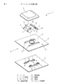
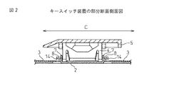
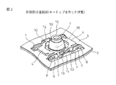
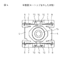
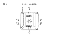
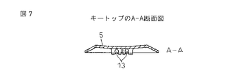
図1は、本発明の第一の実施形態のキースイッチ装置1の斜視分解図を示す。図2は、図1のキースイッチ装置1を組み立てたときの、キートップ非押し下げ時のA方向から見た部分断面図である。図3は、本実施形態のキースイッチ装置1のキートップ5以外を組み立てたときの斜視部分透視図である。図4は、本実施形態のキースイッチ装置1のキートップ5以外を組み立てたときの平面図である。図5は、本実施形態のキースイッチ装置1のキートップ5以外を組み立てたときのリンク部材4の前後方向(図のB方向)の最大のずれを示す平面図である。図6は、キートップ5の背面図を示し、図7は、キートップ5のA-A断面図を示し、図8は、キートップ5のB-B断面図を示す。
FIG. 1 is an exploded perspective view of a key switch device 1 according to a first embodiment of the present invention. FIG. 2 is a partial cross-sectional view seen from the direction A when the key top is not pressed down when the key switch device 1 of FIG. 1 is assembled. FIG. 3 is a perspective view of a part of the key switch device 1 according to the present embodiment other than the
図1は、本発明の第一の実施形態のキースイッチ装置1の斜視分解図を示す。キースイッチ装置1は、ベース2と、ベース2上に配置されるキートップ5と、互いに連動して該キートップ5をベース2上で昇降方向へ案内支持する一対のリンク部材4と、キートップ5の昇降動作に対応して電気回路の接点18(図3参照のこと)を開閉するスイッチ機構19とを有する。一対のリンク部材4の各々は、ベース2に摺動自在に係合する摺動部である摺動支軸8を2つずつ有する。ベース2は、摺動支軸8に摺動自在に係合する摺動係合部である立て板部7を4つ有する。そして、一対のリンク部材4は、相互に噛み合うギア部であるギア凹部12とギア凸部11とをそれぞれに有する。一対のリンク部材4の各々が、キートップ5に係合する回転部である回転支軸10を2つ有する。キートップ5は、回転支軸10に回転可能に係合する軸受部13を4つ有している。また、スイッチ機構19はメンブレンスイッチシート3とラバードーム15を有し、メンブレンシートスイッチ3のリンク部材4が位置する部分に貫通穴6を設けている。リンク部材4の摺動支軸8はメインプレンシート3の貫通穴6上で、貫通穴6から突出したベース2の立て板部7の案内孔9にて摺動する。キースイッチ装置1は、キートップ5を一対の前記リンク部材4に取り付ける際に生じ得るそれぞれのギア凹部12とギア凸部11との相互の位置ずれを防止する位置ずれ防止機構を設けている。この位置ずれ防止機構は、リンク部材4に対してスイッチ機構19の接点18(図3参照のこと)とは反対側であって、各リンク部材4の回転支軸10に隣接して(すなわち各リンク部材4の外側で)、ベース2に設けられる壁部14を有する。
FIG. 1 is an exploded perspective view of a key switch device 1 according to a first embodiment of the present invention. The key switch device 1 includes a
キースイッチ装置1を組み立てる方法の概略を説明する。図1のベース2にメンブレンシートスイッチ3を載せる。次にリンク部材4の摺動支軸8を、立て板部7の案内孔9に入れながら、リンク部材4のギア凹部12とギア凸部11とを互いに係合させて、ベース2上に平らに置く(図3参照のこと)。次にキートップ5の4個の軸受部13(図6参照のこと)を一対のリンク部材4の上方から、それぞれのリンク部材4の計4個の回転支軸10に個々に嵌め込む。
An outline of a method for assembling the key switch device 1 will be described. A
この際、壁部14は、リンク部材4の摺動支軸8が係合する立て板部7に対して、スイッチ機構19の接点18とは反対側であって、リンク部材4の回転支軸10の外側に、板金部材に一体的に切り起こされて配置されている。この壁部14を配置することによって、一対のリンク部材4の前後方向(図2のC方向を参照のこと)のずれを抑制することが出来る。(図5より、リンク部材4のずれが壁部14により制限されて、リンク部材4が外れないことがわかる。)またこの壁部14は、リンク部材4にキートップ5を嵌め込むときの軸受部13の案内にもなる。更に、ギア凹部12とギア凸部11の外側に壁部14を設けることで、キートップ5をリンク部材4に嵌める際に、キートップ5の片側に並ぶ一対の軸受部13(図6参照のこと)を、一対のリンク部材4の対応側の回転支軸10に係合させてから、次に、キートップ5の反対側の一対の軸受部13を各々のリンク部材4の対応側の回転支軸10係合させるような構造上望ましくない取り付け方を防止し、4つの回転支軸10に対して、キートップ5の4つの軸受部13をほぼ同時に取り付けることができるような構造を有する。
In this case, the
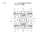
図9〜図12は、本発明の第二の実施形態によるキースイッチ装置60を示す。キースイッチ装置60は、壁部64が第一の実施形態によるキースイッチ装置1と異なる点を除いて、実質的に同一の構成を有する。従って、対応する構成要素には、共通の参照符号を付してその説明を省略する。
9 to 12 show a
図9で示すように、位置ずれ防止機構は、リンク部材4に対して接点18(図10参照のこと)と同じ側であって、各リンク部材4の回転支軸10の根元部分に隣接して(すなわち各リンク部材4の内側で)、ベース2に設けられる壁部64を有する。この壁部64を配置することによって、一対のリンク部材4の前後方向(図2のC方向を参照のこと)のずれを抑制することが出来る(図12より、リンク部材4のずれが壁部64により制限されて、リンク部材4が外れないことがわかる)。またこの壁部64は、リンク部材4にキートップ5を嵌め込むときの軸受部13の案内にもなる。リンク部材4に対して、接点18側に壁部64を設けなければならないので、ラバードーム15を小さくする必要がある。
As shown in FIG. 9, the misalignment prevention mechanism is on the same side as the contact 18 (see FIG. 10) with respect to the link member 4, and is adjacent to the root portion of the
図13は、本発明の第三の実施形態によるキースイッチ装置70を示す。キースイッチ装置70は、壁部74、リンク部材47及びメンブレンシートスイッチ37が第一の実施形態によるキースイッチ装置1と異なる点を除いて、実質的に同一の構成を有する。従って、対応する構成要素には、共通の参照符号を付してその説明を省略する。図14は、リンク部材47の斜視図を示し、図15はリンク部材47の平面図と正面図を示し、図16はリンク部材47のA-A断面図を示す。
FIG. 13 shows a
図13に示すように、リンク部材47の各々は、2個の摺動部である摺動支軸8を有するとともに、それら摺動支軸8の間の位置に形成されるスリット16(図14参照のこと)を有し、位置ずれ防止機構は、スリット16に係合可能にベース2に設けられる壁部74を有する。更に壁部74が突出するようにメンブレンシートスイッチ37には貫通穴6aが設けられている。
As shown in FIG. 13, each of the
壁部74は、リンク部材47の摺動支軸8が係合する立て板部7の間の板金部材に一体的に切り起こされて配置されている。この壁部74がリンク部材47のスリット16に係合することにより、対向するリンク部材47の前後方向のずれを抑制することが出来る。立て板部7の間に壁部74を設けるには、ラバードーム15の大きさを小さくするか、壁部74を小さくする必要がある。更に壁部74がギア凹部12とギア凸部11から離れているので、スリット16との係合が前の二つの実施形態よりも弱くなる。
The
図17〜19は、本発明の第四の実施形態によるキースイッチ装置80を示す。キースイッチ装置80は、壁部14、64、74がなく、回転支軸108、結果的にリンク部材48が第一の実施形態によるキースイッチ装置1と異なる点を除いて、実質的に同一の構成を有する。従って、対応する構成要素には、共通の参照符号を付してその説明を省略する。
17 to 19 show a key switch device 80 according to a fourth embodiment of the present invention. Key switch 80, the
位置ずれ防止機構として、リンク部材48の回転部である回転支軸108は、スイッチ機構19の接点18に隣接する側に配置されている。
As a misalignment prevention mechanism, a
前述した実施形態では、リンク部材4、47の回転支軸10は、リンク部材4、47に対してスイッチ機構19の接点18と反対側に配置されていた。そのため、図9、図13の場合には、キートップ5をリンク部材4、47に嵌める際に、キートップ5の片側に並ぶ一対の軸受部13を、一対のリンク部材4、47の対応側の回転支軸10に係合させてから、次に、キートップ5の反対側の一対の軸受部13を一対のリンク部材4、47の対応側の回転支軸10に係合させるような、構造上望ましくない取り付け方が行なわれる場合があった。このような状態でキートップ5をリンク部材4、47に嵌めると、ギア凹部12とギア凸部11が破損するなどの不具合が発生する可能性がある。このような不具合を回避するためには、上述した不正な係合方法を防止して、キートップ5の軸受部13をリンク部材4、47の真上からリンク部材4、47の回転支軸10に係合させることが必要である。
In the above-described embodiment, the
本実施形態では、リンク部材48の回転支軸108をリンク部材48に対して、スイッチ機構19の接点18の反対側ではなく、接点18(図18参照のこと)側に配置しているので、上述した不正な係合方法が防止されて、キートップ5をリンク部材48に係合時に、リンク部材48が安定し、結果的にギア凹部12とギア凸部11とのずれを防止する。また、上から見ると矩形状に見える図19の空所17にキートップ5の軸受部13(図5参照のこと)を挿入するので、リンク部材48とキートップ5の相対的な位置決めが容易になる。更に、板金構造は型構造(例えば、プラスチックの一体成型で作られた場合)に比べて薄いので、前述した実施形態のように壁部14、64、74(図1、図9および図13参照のこと)をリンク部材4の位置決めに寄与するように形成するのは難しいが、本実施形態の場合には、壁部14、64、74を形成しなくてよいという利点も有する。
In the present embodiment, the
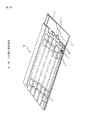
図20は、前述した第一実施形態によるキースイッチ装置1を複数個、所定位置配列して備えた本発明の第一の実施形態によるキーボード90の切欠き斜視図である。キーボード90は、キートップ5取り付け時にリンク部材4がずれないためと、キートップ5のリンク部材4への上述した構造上望ましくない取り付け方を防止するための壁部14を有するキースイッチ装置1を有するので、長期間使用していてもキートップ5が外れにくいだけでなく、リンク部材4が壊れにくいという利点を有する。もちろん第二〜第四の実施形態によるキースイッチ装置60、70、80を使用することもできる。
FIG. 20 is a cutaway perspective view of the keyboard 90 according to the first embodiment of the present invention in which a plurality of key switch devices 1 according to the first embodiment described above are arranged in a predetermined position. The keyboard 90 includes the key switch device 1 having a
1 キースイッチ装置
2 ベース
3 メンブレンシートスイッチ
4 リンク部材
5 キートップ
6 貫通穴
6a 貫通穴
7 立て板部
8 摺動支軸
9 案内孔
10 回転支軸
11 ギア凸部
12 ギア凹部
13 軸受部
14 壁部
15 ラバードーム
16 スリット
17 空所
18 接点
19 スイッチ機構
90 キーボード
DESCRIPTION OF SYMBOLS 1
Claims (5)
前記一対のリンク部材は、相互に噛み合うギア部をそれぞれに有し、
前記一対のリンク部材の各々が、前記キートップに係合する回転部を有すると共に、前記キートップが、前記回転部に回転可能に係合する軸受部を有する、キースイッチ装置において、
前記キートップを一対の前記リンク部材に取り付ける際に生じ得る、それぞれの前記ギア部の相互の位置ずれを防止する位置ずれ防止機構を備え、
前記位置ずれ防止機構は、前記ベースに設けられる壁部であって、前記キートップを前記一対のリンク部材に取り付けるときに前記軸受部の案内になる壁部を有する、
ことを特徴とするキースイッチ装置。 A base, a key top disposed on the base, a pair of link members that guide and support the key top in the ascending / descending direction on the base, and an electric circuit corresponding to the ascending / descending operation of the key top A switch mechanism for opening and closing the contact of the
Each of the pair of link members has a gear portion that meshes with each other,
In each of the pair of link members, the key switch device includes a rotating portion that engages with the key top, and the key top includes a bearing portion that rotatably engages with the rotating portion.
A misalignment prevention mechanism for preventing misalignment between the gear portions, which may occur when the key top is attached to the pair of link members;
The positional displacement prevention mechanism is a wall portion provided on the base, and has a wall portion that serves as a guide for the bearing portion when the key top is attached to the pair of link members .
A key switch device characterized by that.
Priority Applications (4)
| Application Number | Priority Date | Filing Date | Title |
|---|---|---|---|
| JP2006220072A JP4901360B2 (en) | 2006-08-11 | 2006-08-11 | Key switch device and keyboard having key switch device |
| TW096127121A TWI402877B (en) | 2006-08-11 | 2007-07-25 | A key switch device and a keypad having a key switch device |
| US11/889,053 US8101879B2 (en) | 2006-08-11 | 2007-08-08 | Key switch and keyboard having the same |
| CN2007101408836A CN101123144B (en) | 2006-08-11 | 2007-08-10 | Key switch and keyboard having the same |
Applications Claiming Priority (1)
| Application Number | Priority Date | Filing Date | Title |
|---|---|---|---|
| JP2006220072A JP4901360B2 (en) | 2006-08-11 | 2006-08-11 | Key switch device and keyboard having key switch device |
Publications (3)
| Publication Number | Publication Date |
|---|---|
| JP2008047351A JP2008047351A (en) | 2008-02-28 |
| JP2008047351A5 JP2008047351A5 (en) | 2009-08-13 |
| JP4901360B2 true JP4901360B2 (en) | 2012-03-21 |
Family
ID=39049559
Family Applications (1)
| Application Number | Title | Priority Date | Filing Date |
|---|---|---|---|
| JP2006220072A Expired - Fee Related JP4901360B2 (en) | 2006-08-11 | 2006-08-11 | Key switch device and keyboard having key switch device |
Country Status (4)
| Country | Link |
|---|---|
| US (1) | US8101879B2 (en) |
| JP (1) | JP4901360B2 (en) |
| CN (1) | CN101123144B (en) |
| TW (1) | TWI402877B (en) |
Families Citing this family (5)
| Publication number | Priority date | Publication date | Assignee | Title |
|---|---|---|---|---|
| JP5453383B2 (en) * | 2011-12-12 | 2014-03-26 | レノボ・シンガポール・プライベート・リミテッド | Key switch device |
| JP6009211B2 (en) * | 2012-04-26 | 2016-10-19 | 富士通コンポーネント株式会社 | Keyboard device |
| JP6632795B2 (en) * | 2014-09-26 | 2020-01-22 | 富士通コンポーネント株式会社 | Key switch device and keyboard |
| WO2016180296A1 (en) * | 2015-05-09 | 2016-11-17 | 陈�峰 | Key switch device provided with scissor limitation mating surface and having mating portions mated in surface-to-surface manner |
| JP6711145B2 (en) | 2016-06-02 | 2020-06-17 | オムロン株式会社 | Switch, keyboard, and switch manufacturing method |
Family Cites Families (10)
| Publication number | Priority date | Publication date | Assignee | Title |
|---|---|---|---|---|
| TW281743B (en) * | 1995-08-11 | 1996-07-21 | Fujitoru Takamisawa Parts Co Ltd | Keyswitch having a reduced height and a keyboard using such a keyswitch |
| US5813521A (en) * | 1995-08-11 | 1998-09-29 | Fujitsu Takamisawa Component Limited | Keyswitch having a reduced height and a keyboard using such a keyswitch |
| JPH113628A (en) | 1997-06-10 | 1999-01-06 | Fujitsu Takamizawa Component Kk | Key switch and keyboard |
| CN1084004C (en) * | 1997-11-28 | 2002-05-01 | 鸿海精密工业股份有限公司 | Button device |
| JP4342063B2 (en) * | 1999-12-28 | 2009-10-14 | 富士通コンポーネント株式会社 | Key switch device and keyboard |
| JP4608833B2 (en) * | 2001-09-17 | 2011-01-12 | ブラザー工業株式会社 | Key switch, keyboard with key switch, and electronic device with keyboard |
| JP2003197059A (en) * | 2001-12-27 | 2003-07-11 | Alps Electric Co Ltd | Key switch device and keyboard device |
| JP2004139752A (en) * | 2002-10-15 | 2004-05-13 | Fujitsu Component Ltd | Key switch device and keyboard |
| JP4562576B2 (en) | 2004-07-01 | 2010-10-13 | 富士通コンポーネント株式会社 | Key switch device, keyboard and key switch assembly jig |
| TWM291045U (en) * | 2005-12-13 | 2006-05-21 | Sunrex Technology Corp | Thin-film switch of a keyboard |
-
2006
- 2006-08-11 JP JP2006220072A patent/JP4901360B2/en not_active Expired - Fee Related
-
2007
- 2007-07-25 TW TW096127121A patent/TWI402877B/en not_active IP Right Cessation
- 2007-08-08 US US11/889,053 patent/US8101879B2/en not_active Expired - Fee Related
- 2007-08-10 CN CN2007101408836A patent/CN101123144B/en not_active Expired - Fee Related
Also Published As
| Publication number | Publication date |
|---|---|
| TW200826129A (en) | 2008-06-16 |
| CN101123144A (en) | 2008-02-13 |
| CN101123144B (en) | 2012-03-14 |
| US20080035461A1 (en) | 2008-02-14 |
| TWI402877B (en) | 2013-07-21 |
| US8101879B2 (en) | 2012-01-24 |
| JP2008047351A (en) | 2008-02-28 |
Similar Documents
| Publication | Publication Date | Title |
|---|---|---|
| JP4562576B2 (en) | Key switch device, keyboard and key switch assembly jig | |
| JP4698514B2 (en) | Key switch device and keyboard | |
| JP4721908B2 (en) | Key switch device | |
| JP2009076321A (en) | Keyswitch device and keyboard | |
| JP4901360B2 (en) | Key switch device and keyboard having key switch device | |
| JP2008047351A5 (en) | ||
| JP4869316B2 (en) | Key switch device and keyboard | |
| JP4518706B2 (en) | Key switch device and keyboard | |
| CN108346542B (en) | Keyboard device | |
| US20080277255A1 (en) | Keyswitch with balance member | |
| JP4817999B2 (en) | Key switch device and keyboard | |
| JP4342063B2 (en) | Key switch device and keyboard | |
| JP5072903B2 (en) | Key switch device and keyboard | |
| JP4703709B2 (en) | Key switch device and keyboard | |
| JP2008251461A (en) | Keyboard | |
| JP6274873B2 (en) | keyboard | |
| TWI835577B (en) | Keyswitch with quick assembly property and related keyboard | |
| JP5590967B2 (en) | High profile key switch device | |
| JP4112960B2 (en) | keyboard | |
| JP4698513B2 (en) | Key switch device and keyboard | |
| JP5291562B2 (en) | Electronics | |
| JP5072904B2 (en) | Key switch device and keyboard | |
| JP5435079B2 (en) | Electronics | |
| JP2001125705A (en) | Key switch device and keyboard | |
| JP5094784B2 (en) | Key switch device and keyboard |
Legal Events
| Date | Code | Title | Description |
|---|---|---|---|
| A521 | Written amendment |
Free format text: JAPANESE INTERMEDIATE CODE: A523 Effective date: 20090626 |
|
| A621 | Written request for application examination |
Free format text: JAPANESE INTERMEDIATE CODE: A621 Effective date: 20090626 |
|
| A977 | Report on retrieval |
Free format text: JAPANESE INTERMEDIATE CODE: A971007 Effective date: 20110215 |
|
| A131 | Notification of reasons for refusal |
Free format text: JAPANESE INTERMEDIATE CODE: A131 Effective date: 20110222 |
|
| A521 | Written amendment |
Free format text: JAPANESE INTERMEDIATE CODE: A523 Effective date: 20110422 |
|
| A131 | Notification of reasons for refusal |
Free format text: JAPANESE INTERMEDIATE CODE: A131 Effective date: 20110712 |
|
| A521 | Written amendment |
Free format text: JAPANESE INTERMEDIATE CODE: A523 Effective date: 20110912 |
|
| TRDD | Decision of grant or rejection written | ||
| A01 | Written decision to grant a patent or to grant a registration (utility model) |
Free format text: JAPANESE INTERMEDIATE CODE: A01 Effective date: 20111129 |
|
| A01 | Written decision to grant a patent or to grant a registration (utility model) |
Free format text: JAPANESE INTERMEDIATE CODE: A01 |
|
| A61 | First payment of annual fees (during grant procedure) |
Free format text: JAPANESE INTERMEDIATE CODE: A61 Effective date: 20111227 |
|
| R150 | Certificate of patent or registration of utility model |
Ref document number: 4901360 Country of ref document: JP Free format text: JAPANESE INTERMEDIATE CODE: R150 Free format text: JAPANESE INTERMEDIATE CODE: R150 |
|
| FPAY | Renewal fee payment (event date is renewal date of database) |
Free format text: PAYMENT UNTIL: 20150113 Year of fee payment: 3 |
|
| R250 | Receipt of annual fees |
Free format text: JAPANESE INTERMEDIATE CODE: R250 |
|
| S531 | Written request for registration of change of domicile |
Free format text: JAPANESE INTERMEDIATE CODE: R313531 |
|
| R350 | Written notification of registration of transfer |
Free format text: JAPANESE INTERMEDIATE CODE: R350 |
|
| R250 | Receipt of annual fees |
Free format text: JAPANESE INTERMEDIATE CODE: R250 |
|
| R250 | Receipt of annual fees |
Free format text: JAPANESE INTERMEDIATE CODE: R250 |
|
| R250 | Receipt of annual fees |
Free format text: JAPANESE INTERMEDIATE CODE: R250 |
|
| R250 | Receipt of annual fees |
Free format text: JAPANESE INTERMEDIATE CODE: R250 |
|
| LAPS | Cancellation because of no payment of annual fees |