JP4901030B2 - Piano hammer and hammerwood - Google Patents
Piano hammer and hammerwood Download PDFInfo
- Publication number
- JP4901030B2 JP4901030B2 JP2001254457A JP2001254457A JP4901030B2 JP 4901030 B2 JP4901030 B2 JP 4901030B2 JP 2001254457 A JP2001254457 A JP 2001254457A JP 2001254457 A JP2001254457 A JP 2001254457A JP 4901030 B2 JP4901030 B2 JP 4901030B2
- Authority
- JP
- Japan
- Prior art keywords
- hammerwood
- hammer
- wood
- core material
- rigidity
- Prior art date
- Legal status (The legal status is an assumption and is not a legal conclusion. Google has not performed a legal analysis and makes no representation as to the accuracy of the status listed.)
- Expired - Fee Related
Links
Images


Description
【0001】
【発明の属する技術分野】
本発明は、ピアノ用ハンマー及びこれを構成するハンマーウッドに関する。
【0002】
【従来の技術】
ピアノ用ハンマー(以下、単に「ハンマー」という)の打弦特性は、ピアノの音色や音質のみならず、演奏者のタッチ感や奏法上の性能といったピアノの各種性能を左右する。このため、その特性を良好に保持することは極めて重要である。
【0003】
例えば、このようなハンマーの打弦特性を評価する指標の一つとして、打弦時の弦への接触時間がある。この接触時間は特に高音域ほど問題となる。すなわち、打弦時において高音域では基本音に対して特に周波数の高い倍音が重畳することになるが、接触時間が長くなるとハンマーフェルトの接触によるダンパ作用によりこの倍音が消されてしまう。その結果、この倍音の重畳による豊かな発音ができなくなる。さらに接触時間が長くなると、基本音さえも消えてしまうことになる。このため、特に高音域側においては接触時間を短くすることが要請される。そして、この接触時間を短くするためには、ハンマーを軽量化してその応答性を向上させる必要がある。
【0004】
また、奏法上の性能の一つとして、高音域のみならず中・低音域においても連打性が重要視されるが、この連打性を高めるためにはハンマーをスピーディーに動作させる必要があり、そのためにはハンマーを軽量化する必要がある。
ところで、ハンマーを軽量化するには、ハンマーを構成するハンマーフェルト及びハンマーウッドのいずれか又は双方を軽量化することになるが、ピアノの優れた音色や音質を確保するためには、ハンマーフェルトの厚み及び硬さをある程度確保する必要がある。このため、従来この軽量化を実現するためには、ハンマーウッド側の材質として軽いものを選択する方法がとられていた。
【0005】
【発明が解決しようとする課題】
しかしながら、後述する実施例でも述べるように、ハンマーの製造工程においてハンマーフェルトをハンマーウッドに組み付ける際には、ハンマーウッドの先端部をハンマーフェルトに強圧してハンマーフェルトを巻き付けることになる。このため、ハンマーウッドに軸方向に大きな押圧力が加わり、ハンマーウッドを構成する木材の種類(樹種)の選択によっては、その押圧工程でハンマーウッドが座屈してしまう虞があった。特に、高音域側のハンマーウッドは構造上その先端部の厚みが小さくなるため、この問題が顕著であった。
【0006】
そのため、実際にはハンマーウッドに用いる樹種として座屈が発生しない範囲で軽いものを選択することが行われており、ハンマーウッドひいてはハンマーの軽量化には一定の限界があった。
本発明は、このような問題に鑑みてなされたものであり、ハンマーウッドの剛性を一定以上に保持しつつ軽量化を実現することで、ハンマーの製造に支障を生じさせることなくハンマー全体を軽量化し、それにより、ピアノの打弦特性を向上させることを目的とする。
【0007】
【課題を解決するための手段】
上記課題に鑑み、請求項1に記載のハンマーウッドは、木材からなる長尺状の本体の少なくとも先端部に、その長手方向に沿ってこの木材よりも硬度の高い長尺状の芯材を埋設して構成されている。また、芯材は炭素繊維強化複合材料またはガラス繊維強化複合材料から構成され、木材として、比重が0.3〜0.5の樹種が採用されている。
またこのハンマーウッドは、木材に長手方向に延びる収容孔を形成し、この収容孔と略同じ断面を有する長尺状の芯材を収容して形成されている。そして、上記本体が、二枚の長尺平板状の木材を接合して構成され、上記収容孔が、該二枚の木材の接合面の対応する位置に夫々設けられた収容溝を組合せて形成されている。
【0008】
ここで、「少なくとも先端部」としたのは、ハンマーウッドは高音域側のものほどその構造上先端部の厚みが小さくなっており、その先端部の座屈強度が弱くなるため、芯材による補強をすることとしたものである。ただし、本体を形成する樹種によっては、中・低音域側のものでもその製造工程において座屈が生じる場合もあるので、ハンマーウッドの長手方向全域にわたって芯材を埋設するのがより好ましい。
【0009】
かかる構成によれば、芯材によりハンマーウッドの長手方向の強度が補強されるため、ハンマーウッドの主材料である木材の材質として比重の小さいものを採用することができる。すなわち、一般に木材単体の座屈強度はその比重が大きいほど強くなるため、従来はこの木材単体の座屈強度を基準に許容される限度内において軽い樹種の選択が行われていた。しかし、請求項1記載の構成によれば、芯材による補強分、座屈強度の小さい木材、つまり比重の小さい木材を選択することが可能になる。
【0010】
このため、製造工程におけるハンマーウッドの座屈強度を一定以上に保持した状態で当該ハンマーウッドひいてはハンマーの軽量化を実現することができる。この結果、ハンマーの打弦スピード(応答性)が向上し、ピアノの打弦特性を向上させることができる。
【0011】
ところで、上記ハンマーウッドの軽量化を実現するには、芯材として用いられる材料の選択も重要である。所定の押圧荷重に耐え得るだけでなく、ハンマーウッドの軽量化のために、芯材としても軽いものを用いる必要があるからである。
このような観点から、請求項1に記載のハンマーウッドにおいては、剛性が高くてしかも軽量である炭素繊維強化複合材料からなる芯材が用いられる。
【0012】
この炭素繊維強化複合材料は、例えば炭素繊維に樹脂を浸して焼結したり、或いは、炭素繊維を束ねたものにバインダー(接着剤)を混ぜて硬化させる等により形成することが考えられる。
尚、このような炭素繊維強化複合材料ではなく、ガラス繊維からなるガラス繊維強化複合材料等を用いることもできる。
【0013】
このように芯材による補強構造とすることで、従来はハンマーウッドに使用する樹種としてコチベ(比重:0.75程度)、マンソニア(比重:0.65程度)、マホガニー(比重:0.63程度)等を選択するが一般的であったが、比重が0.3〜0.5程度の樹種を選択することができる。このような樹種としては、例えばスプルース(比重:0.43程度)、エゾマツ(比重:0.43程度)、スギ(比重:0.35程度)等が挙げられる。
【0014】
すなわち、これらの樹種は比重が小さいため剛性に乏しく、従来単体でハンマーウッドに採用することが困難とされていたが、上記芯材による補強により採用することが可能となる。
かかる樹種を選択すれば木材の重量を大幅に低減でき、上述したピアノの打弦特性の向上に極めて有効である。
【0018】
また、かかる構成のハンマーウッドでは、芯材が予め分割された状態でハンマーウッド用合成材中に埋設される。このため、最終の切断工程において芯材を避けた位置でハンマーウッド用合成材を切断でき、切断工具の摩耗や破損を防止することができる。また、切断が容易となるため、作業効率を高めることができる。
【0020】
木材の表面に長手方向の溝を加工するのは比較的容易であるため、かかる構成によれば容易に上記構成を実現することができる。この場合、一方の木材に形成された収容溝に芯材を嵌め込んだ状態で他方の木材を接合する、という簡易な方法によりハンマーウッド用合成材を製造することができる。
【0021】
この場合、芯材としては例えば棒状のものを採用することもできる。しかし、特に高音域のハンマーウッドの先端部は厚みが小さいため、棒状部材の径の大きさが制限されることになる。このため、より剛性を高めるためには、一つのハンマーウッドについて芯材を複数本収容する構造とすることが必要になる。このことは、木材側にも複数の収容溝を設ける必要があることを意味するため、加工が煩雑になり製造コストが嵩む。
【0022】
そこで、請求項2に記載のように、芯材として短冊形状のものを用いることが有効である。
かかる構成によれば、芯材をハンマーウッドの幅方向に大きくとることができ、その剛性を十分に高めることができる。また、各木材側に設ける収容溝も一つのハンマーウッドについて角断面の溝を一つ設ければよいため、加工が容易である。
【0023】
そして、以上に述べたハンマーウッドの先端にハンマーフェルトを取り付けて構成した請求項3に記載のピアノ用ハンマーによれば、ピアノの打弦性能を著しく向上させることができる。
【0024】
【発明の実施の形態】
以下、本発明の好適な実施例を図面に基づいて説明する。
[第1実施例]
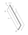
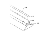
図1(a)は第1実施例に係るハンマーの斜視図であり、同図(b)はこのハンマーを構成するハンマーウッドの斜視図である。
【0025】
同図(a)に示すように、ハンマー1は、長尺状のハンマーウッド10の先端にハンマーフェルト20を装着して構成されており、同図(b)に示すように、ハンマーウッド10は、木材からなる長尺状の本体11の長手方向に沿って補強用の芯材12が埋設されて構成されている。尚、周知のように、ハンマーウッドはその先端部の厚みが高音域側ほど小さくなり、またハンマーフェルトはその厚みが高音域側ほど小さくなるが、同図においては夫々高音域側のものを例示している。
【0026】
次に、ハンマー1の製造方法について図2〜図6に基づいて説明する。
まず、図2(a)に示すように、二枚の長尺平板状のスプルース木材単板13と一枚の長尺平板状の高剛性単板14を用意する。スプルース木材単板13は、比重が0.35程度であり、長さL1が1000mm程度、幅W1(ハンマーウッド10の長手方向の長さに相当)が100mm程度、厚みt1が4mm程度に形成されている。また、芯材12を形成する高剛性単板14は、炭素繊維強化複合材料からなり、その長さ及び幅はスプルース木材単板13とほぼ同一に形成され、厚みt2が2mm程度に形成されている。この炭素繊維複合材料は、炭素繊維を束ねたものにバインダー(接着剤)を混ぜて硬化させることにより形成される。
【0027】
そして、両スプルース木材単板13の間に高剛性単板14を挟み込むようにしてその接合面を接着剤にて接合し、同図(b)に示すハンマーウッド用合成材15を製造する。
尚、本実施例で用いる炭素繊維強化複合材料としては、図9に示す低弾性タイプのもの又は高弾性タイプのものを使用する。同図に、これら炭素繊維強化複合材料及び各種木材のヤング率(Kg/cm2)に示すように、炭素繊維複合材料は、高比重の木材と比較してもその剛性が高いことが分かる。
【0028】
次に、ハンマーウッド用合成材15を、図3に示すように、スプルース木材単板13の幅方向(図中Y方向)における一端側の表裏両面を切削して厚みの薄い先端部16を形成し、他端側の表裏両面は厚いまま残して基部17とする。この切削による先端部16の厚さの調節は、低音域側の先端部16aではほとんど切削されていないため最も厚く、高音域側の先端部16bでは最も薄くなるように、テーパ状に切削されている。尚、この際、高音域側の先端部16bにおいても高剛性単板14がむき出しになることはなく、スプルース木材単板13により完全に覆われている。
【0029】
次に、図4に示すように、所定の厚みを有する長尺平板状のハンマーフェルト20にハンマーウッド用合成材15の先端部16を押し付けながら、ハンマーフェルト20を矢印で示すように先端部16に巻き付ける。図5にハンマーフェルト20の取付工程の詳細を示す。
【0030】
図5(a)に示すように、まず、平滑面上に長手方向に延びる断面円弧形の溝31aが形成された第1金型31に対し、この溝31aに沿ってハンマーフェルト20を載置する。ハンマーフェルト20は断面が台形状になっており、このとき水平面の面積の小さい側を上にして載置する。このハンマーフェルト20の上面には接着剤が塗布されている。
【0031】
続いて、ハンマーフェルト20の上面中央にハンマーウッド用合成材15の先端部16を強圧して所謂仮締めを行う。このとき、ハンマーフェルト20は、同図(b)に示すように、その幅方向の中央下面が溝31aに沿って変形すると共に、その両端部がハンマーウッド用合成材15側(上方)に撓む。
【0032】
そして、この状態から左右に設置された一対の第2金型32を第1金型31の上面に沿ってハンマーウッド用合成材15側に駆動し、ハンマーフェルト20の両端部下面に押し付け、所謂本締めを行う。この第2金型32のハンマーフェルト20への当接面32aは、その上方に向かうほどハンマーウッド用合成材15側に接近するように傾斜しているため、同図(c)に示すように、ハンマーフェルト20は、ハンマーウッド用合成材15の先端部16を巻き込むように押し付けられて接合される。この状態を図6(a)に示す。このとき、ハンマーフェルト20は、低音域側20aで最も厚く、高音域側20bでは最も薄くなるように形成されている。
【0033】
次に、ハンマーウッド用合成材15とハンマーフェルト20との一体物を、Y方向の面を切断面として切断して、各ハンマー1を所定の幅に順次分離形成する。これにより、同図(b)に示すように、低音域のハンマー1aの先端部(ハンマーフェルト20側)は厚く、中音域のハンマー1bの先端部は少し薄く、高音域用のハンマー1cの先端部は最も薄くなり、ピアノ一台分のハンマー列(ハンマーウッド列)が完成する。
【0034】
以上に説明したように、本実施例のハンマー1においては、ハンマーウッド10に芯材12として高剛性の炭素繊維強化複合材料が埋設されているため、ハンマー1の製造時において、ハンマーウッド10をハンマーフェルト20に強圧する工程でのハンマーウッド10の座屈を効果的に防止することができる。
【0035】
また、このように芯材12を埋設することによりハンマーウッド10の強度を確保することができるため、ハンマーウッド10の主たる材料として比重の小さいスプルース木材を使用することができる。このため、ハンマー1全体の軽量化を実現することができ、打弦時の応答性を向上させることができる。この結果、特に高音域側で重畳する高次倍音を消すことなく保持することができ、音色、音質を損なうことなく、豊かな発音をさせることができる。また、かかる応答性の向上により、連打性等の奏法上の特性を優位に保つことができ、演奏者の技量を十分に反映させることができる。
【0036】
尚、本実施例のハンマーウッド10の構成によれば、ハンマーウッド用合成材15を製造した段階において、炭素繊維強化複合材料がその長手方向の両端に露出した状態となっている。この炭素繊維強化複合材料は熱伝導性に優れるためため、例えばこの炭素繊維強化複合材料の両端に電極を接続して通電することにより、ハンマーフェルト20との接合部周辺を加熱してハンマーフェルト20を一時的に軟らかくし、その先端部16への巻き付けを容易にすることができる。また、この加熱により接合部に介在する接着剤の乾燥を早めることもでき、全体としてハンマーフェルト20の接合の効率化を図ることができる。
[第2実施例]
上記第1実施例では、ハンマーウッド用合成材15の製造段階において、二枚のスプルース木材単板13の間に一枚の高剛性単板14を挟み、これをその長手方向に切断して分割する方法をとった。この方法は、多数(一般には88鍵分)のハンマーを効率よく製造する点で優れるが、最後の切断工程の際に高剛性単板14をも切断する必要があるため、切断工具を摩耗又は破損させる恐れがある。
【0037】
そこで、本実施例では、このような切断時の便宜に供する構造を有するハンマーウッドの構造について説明する。尚、本実施例においては、スプルース木材単板と高剛性材の組付構造が異なる以外は第1実施例と同様であるので、同様の構成についてはその説明を省略する。
【0038】
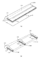
図7(a)に本実施例のハンマーウッド210の斜視図を示すように、ハンマーウッド210は、長尺状の本体211の中央に軸方向に沿って棒状の芯材212が埋設されている。このハンマーウッド210の製造方法を図8に基づいて説明する。
【0039】
まず、図8に示すように、二枚の長尺状のスプルース木材単板213と、芯材212を構成する複数の棒状(円柱状)の高剛性材214とを用意する。スプルース木材単板213は、比重が0.35程度であり、その概形が長さL21が1000mm程度、幅W21(ハンマーウッドの長手方向の長さに相当)が100mm程度、厚みt21が5mm程度に形成されている。一方、高剛性材214は炭素繊維強化複合材料からなり、直径が2mm程度、長さがスプルース木材単板213の幅W21と同一となるように形成されている。そして、二枚のスプルース木材単板213の互いに対向する面には、幅方向に延びる断面半円形状の収容溝213aが長手方向に所定の間隔をもって複数(本実施例では88個)形成されている。この収容溝213aの径は高剛性材214の径とほぼ同様の2mm程度に形成されており、この収容溝213aが対向して形成される断面円形の収容孔に高剛性材214を収容可能に構成されている。
【0040】
そして、両スプルース木材単板213の接合面及び収容溝213aに接着剤を塗布し、各収容溝213aに高剛性材214を収容した後、両スプルース木材単板213を接合し、ハンマーウッド用合成材215を製造する。
次に、このハンマーウッド用合成材215を、第1実施例と同様に、スプルース木材単板213の幅方向における一端側の表裏両面を切削して厚みの薄い先端部216を形成する。このときの状態を表す平面図を同図(b)に示す。
【0041】
そして、このハンマーウッド用合成材215にハンマーフェルト(図示せず)を取り付けた後、同図(c)に示すように、その長手方向(図中X方向)に沿って所定の間隔S(本実施例では10mm)で切断することにより、各ハンマーが完成する。尚、この切断位置は隣接する芯材間の中央位置に設定され、本実施例においては、ハンマーウッド用合成材215の長手方向の一端面を基準に算出される。
【0042】
以上に説明したように、本実施例のハンマーウッド210においては、高剛性材214が予め分割された状態でハンマーウッド用合成材215中に埋設されている。このため、最終の切断工程においてその高剛性材214を避けた位置でハンマーウッド用合成材215を切断でき、切断工具の摩耗や破損を防止することができる。また、切断が容易であるため、作業効率を高めることができる。
[変形例]
図7(b)に上記第2実施例の変形例を示す。
【0043】
本変形例にかかるハンマーウッド310では、高剛性材312として上記のような棒状のものではなく、短冊状のものを採用している。すなわち、高剛性材312は、その長さがハンマーウッド310の長さに等しいが、その幅はハンマーウッド310の幅よりやや小さくなっている。
【0044】
すなわち、本ハンマーウッド310の製造においては、高剛性材312として長尺板状(断面長方形状)のものを用い、収容溝の形状としてこの高剛性材312を収容可能な角溝を形成する。それ以外は、図8に示した上記第2実施例の製造方法と同様である。
【0045】
本変形例に係るハンマーウッド310によれば、上記第2実施例のように、予め高剛性材312を分割した状態でハンマーウッド用合成材中に埋設するため、最終の切断工程においてその高剛性材312を避けた位置でハンマーウッド用合成材を切断でき、切断工具の摩耗や破損を防止することができる。そしてさらに、上記第2実施例のように棒状の高剛性材を用いた場合よりも高剛性材312の断面を大きくとることができるため、ハンマーウッド用合成材の剛性を高めることができる。このため、製造工程において座屈等が生じる可能性がより少なくなる。
【0046】
以上、本発明の実施例について説明したが、本発明の実施の形態は、上記実施例に何ら限定されることなく、本発明の技術的範囲に属する限り種々の形態をとり得ることはいうまでもない。
例えば、上記各実施例においては、製造方法の都合上、高剛性材の両端面がハンマーウッドの端面から露出する構造となるが、収容溝を段状に形成して高剛性材を木材中に完全に収容するように構成すれば、高剛性材が外部に露出しない構成とすることもできる。
【0047】
また、上記各実施例のハンマーにおいては、ハンマーフェルトとして単層構造のものを採用した例を示したが、所謂アンダーフェルトを有する二層構造のものを採用することもできる。
また、上記各実施例では、木材単板の樹種としてスプルースを採用した例を示したが、比較的比重の小さいスギ、エゾマツ、その他の樹種を採用してもよい。
【0048】
さらに、上記各実施例では、予めハンマーウッド用合成材を一体成形し、これをその長手方向に順次切断して複数のハンマーウッドを形成する製造方法を示したが、予め複数の木材単板を個々のハンマーウッド毎に形成し、その個々に高剛性材を埋設して形成してもよい。
【図面の簡単な説明】
【図1】 本発明の第1実施例に係るハンマー及びハンマーウッドの斜視図である。
【図2】 第1実施例のハンマーの製造方法を表す説明図である。
【図3】 第1実施例のハンマーの製造方法を表す説明図である。
【図4】 第1実施例のハンマーの製造方法を表す説明図である。
【図5】 第1実施例のハンマーの製造方法を表す説明図である。
【図6】 第1実施例のハンマーの製造方法を表す説明図である。
【図7】 本発明の第2実施例及びその変形例に係るハンマーウッドの斜視図である。
【図8】 第2実施例のハンマーウッドの製造方法を表す説明図である。
【図9】 炭素繊維材と各種木材の剛性を表す説明図である。
【符号の説明】
1・・・ピアノ用ハンマー、 10,210,310・・・ハンマーウッド、
11,211・・・本体、 12,212,312・・・芯材、
15,215・・・ハンマーウッド用合成材、 20・・・ハンマーフェルト[0001]
BACKGROUND OF THE INVENTION
The present invention relates to a piano hammer and a hammerwood constituting the hammer.
[0002]
[Prior art]
The stringing characteristics of a piano hammer (hereinafter simply referred to as “hammer”) affect not only the tone and tone quality of the piano, but also various performances of the piano, such as the player's touch and performance. For this reason, it is extremely important to maintain the characteristics well.
[0003]
For example, as one index for evaluating the stringing characteristics of such a hammer, there is a contact time with the string at the time of stringing. This contact time becomes a problem especially in the high sound range. In other words, overtones with a particularly high frequency are superimposed on the basic sound in the high sound range when the string is struck, but when the contact time is increased, the overtones are eliminated by the damper action caused by the contact of the hammer felt. As a result, rich pronunciation by superimposing the harmonics cannot be performed. If the contact time becomes longer, even basic sounds will disappear. For this reason, it is required to shorten the contact time particularly on the high sound range side. In order to shorten the contact time, it is necessary to reduce the weight of the hammer and improve its responsiveness.
[0004]
Also, as one of the performance performances, continuous hitting is important not only in the high range but also in the middle and low range. To improve this hit, it is necessary to operate the hammer speedily. It is necessary to reduce the weight of the hammer.
By the way, in order to reduce the weight of the hammer, either or both of the hammer felt and the hammerwood constituting the hammer must be reduced in weight, but in order to ensure the excellent tone and quality of the piano, It is necessary to secure a certain thickness and hardness. For this reason, conventionally, in order to achieve this weight reduction, a method of selecting a light material as the material on the hammerwood side has been taken.
[0005]
[Problems to be solved by the invention]
However, as will be described in the embodiments described later, when the hammer felt is assembled to the hammerwood in the hammer manufacturing process, the hammer felt is wound with the tip of the hammerwood being strongly pressed against the hammer felt. For this reason, a large pressing force is applied to the hammer wood in the axial direction, and depending on the selection of the type of wood (tree species) constituting the hammer wood, the hammer wood may be buckled in the pressing step. In particular, the hammer wood on the high sound range side has a remarkable problem because of its structurally small tip.
[0006]
Therefore, in practice, light wood is selected as a tree species used for hammerwood as long as buckling does not occur, and there is a certain limit to the weight reduction of the hammerwood and the hammer.
The present invention has been made in view of such problems, and by reducing the weight while maintaining the rigidity of the hammerwood above a certain level, the entire hammer can be reduced in weight without causing any hindrance to the manufacture of the hammer. Therefore, it aims at improving the stringing characteristic of the piano.
[0007]
[Means for Solving the Problems]
In view of the above problems, the hammerwood according to claim 1 embeds a long core material having a hardness higher than that of the wood along the longitudinal direction at least at the tip of a long main body made of wood. Configured. Moreover, the core material is composed of a carbon fiber reinforced composite material or a glass fiber reinforced composite material, and a tree species having a specific gravity of 0.3 to 0.5 is adopted as the wood.
The hammerwood is formed by forming a housing hole extending in the longitudinal direction in the wood and housing a long core material having substantially the same cross section as the housing hole. And the said main body is comprised by joining two elongate flat plate-like timbers, and the said accommodation hole is formed combining the accommodation groove | channel each provided in the position corresponding to the joining surface of these two timbers. Has been.
[0008]
Here, the term “at least the tip portion” means that the hammerwood has a structure whose tip portion has a smaller thickness on the high sound side, and the buckling strength of the tip portion becomes weaker. It is supposed to be reinforced. However, depending on the type of tree forming the main body, buckling may occur in the manufacturing process even on the middle / low range side, so it is more preferable to embed the core material over the entire longitudinal direction of the hammerwood.
[0009]
According to such a configuration, the strength in the longitudinal direction of the hammerwood is reinforced by the core material, so that a material having a small specific gravity can be employed as the material of the wood that is the main material of the hammerwood. In other words, since the buckling strength of a single wood generally increases as the specific gravity increases, conventionally, a light tree species has been selected within the limits allowed based on the buckling strength of this single wood. However, according to the structure of
[0010]
For this reason, it is possible to reduce the weight of the hammerwood and thus the hammer while maintaining the buckling strength of the hammerwood at a certain level or higher in the manufacturing process. As a result, the hammering speed (responsiveness) of the hammer is improved, and the stringing characteristics of the piano can be improved.
[0011]
By the way, in order to realize the weight reduction of the hammerwood, selection of a material used as a core material is also important. This is because it is necessary not only to withstand a predetermined pressing load, but also to use a light core material in order to reduce the weight of the hammerwood.
From such a viewpoint, the hammerwood according to
[0012]
This carbon fiber reinforced composite material may be formed by, for example, immersing a resin in carbon fiber and sintering it, or mixing a carbon fiber bundle with a binder (adhesive) and curing.
In addition, the glass fiber reinforced composite material which consists of glass fiber etc. can also be used instead of such a carbon fiber reinforced composite material.
[0013]
In this way, by using a reinforcing structure with a core material, the tree species conventionally used for hammerwood are Kochibe (specific gravity: about 0.75), Mansonia (specific gravity: about 0.65), mahogany (specific gravity: about 0.63) ), but although selecting such was generally, specific gravity can be selected species of about 0.3 to 0.5. Examples of such tree species include spruce (specific gravity: about 0.43), spruce (specific gravity: about 0.43), cedar (specific gravity: about 0.35), and the like.
[0014]
That is, since these tree species have low specific gravity, they are poor in rigidity, and it has been difficult to adopt them as hammer wood by themselves, but they can be adopted by reinforcement with the core material.
If such a tree species is selected, the weight of the wood can be greatly reduced, which is extremely effective for improving the stringing characteristics of the piano described above.
[0018]
In the hammerwood having such a configuration , the core material is embedded in the hammerwood synthetic material in a state where the core material is divided in advance. For this reason, the hammerwood synthetic material can be cut at a position avoiding the core material in the final cutting step, and wear and breakage of the cutting tool can be prevented. Moreover, since cutting becomes easy, work efficiency can be improved.
[0020]
Since it is relatively easy to machine the longitudinal grooves on the surface of the wood, according to such a configuration, the above configuration can be easily realized. In this case, the hammerwood synthetic material can be manufactured by a simple method in which the other wood is joined in a state in which the core material is fitted in the accommodation groove formed in the one wood.
[0021]
In this case, for example, a rod-shaped material can be used as the core material. However, since the tip of the hammerwood, particularly in the high sound range, is thin, the diameter of the rod-shaped member is limited. For this reason, in order to raise rigidity more, it is necessary to make it the structure which accommodates several core materials about one hammerwood. This means that it is necessary to provide a plurality of receiving grooves on the wood side, so that the processing becomes complicated and the manufacturing cost increases.
[0022]
Therefore, as described in claim 2 , it is effective to use a strip-shaped core material.
According to such a configuration, the core material can be made large in the width direction of the hammerwood, and its rigidity can be sufficiently increased. Moreover, since the accommodation groove | channel provided in each timber side should just provide the groove | channel of one square section about one hammerwood, a process is easy.
[0023]
And according to the hammer for piano of
[0024]
DETAILED DESCRIPTION OF THE INVENTION
Preferred embodiments of the present invention will be described below with reference to the drawings.
[First embodiment]
FIG. 1A is a perspective view of a hammer according to the first embodiment, and FIG. 1B is a perspective view of a hammerwood constituting the hammer.
[0025]
As shown in FIG. 1A, the
[0026]
Next, the manufacturing method of the
First, as shown in FIG. 2A, two long flat plate-like spruce wood
[0027]
And the joining surface is joined with an adhesive so that the high-
In addition, as a carbon fiber reinforced composite material used by a present Example, the thing of the low elastic type or high elastic type shown in FIG. 9 is used. As shown by the Young's modulus (Kg / cm 2) of these carbon fiber reinforced composite materials and various kinds of wood, it can be seen that the carbon fiber composite material has higher rigidity than wood with high specific gravity.
[0028]
Next, as shown in FIG. 3, the hammerwood
[0029]
Next, as shown in FIG. 4, while pressing the
[0030]
As shown in FIG. 5A, first, the hammer felt 20 is placed along the
[0031]
Subsequently, the
[0032]
Then, a pair of
[0033]
Next, the hammerwood
[0034]
As described above, in the
[0035]
Moreover, since the strength of the
[0036]
In addition, according to the structure of the
[Second Embodiment]
In the first embodiment, in the manufacturing stage of the hammerwood
[0037]
Therefore, in this embodiment, the structure of a hammerwood having a structure for convenience in cutting will be described. The present embodiment is the same as the first embodiment except that the assembly structure of the spruce wood veneer and the high-rigidity material is different, so the description of the same configuration is omitted.
[0038]
As shown in the perspective view of the
[0039]
First, as shown in FIG. 8, two long spruce wood
[0040]
Then, an adhesive is applied to the joint surfaces of both the spruce wood veneers 213 and the
Next, the hammerwood
[0041]
And after attaching a hammer felt (not shown) to this hammerwood
[0042]
As described above, in the
[Modification]
FIG. 7B shows a modification of the second embodiment.
[0043]
In the
[0044]
That is, in manufacturing the
[0045]
According to the
[0046]
As mentioned above, although the Example of this invention was described, it cannot be overemphasized that embodiment of this invention can take various forms, as long as it belongs to the technical scope of this invention, without being limited to the said Example at all. Nor.
For example, in each of the above embodiments, for the convenience of the manufacturing method, both ends of the highly rigid material are exposed from the end surface of the hammerwood. However, the housing groove is formed in a step shape so that the highly rigid material is placed in the wood. If it is configured so as to be completely accommodated, it can be configured such that the highly rigid material is not exposed to the outside.
[0047]
Moreover, in the hammer of each said Example, although the example which employ | adopted the thing of a single layer structure as a hammer felt was shown, the thing of a two-layer structure which has what is called an underfelt can also be employ | adopted.
Moreover, although the example which employ | adopted the spruce as a tree seed | species of a wood single board was shown in each said Example, you may employ | adopt cedar, a spruce, and other tree species with comparatively small specific gravity.
[0048]
Further, in each of the above-described embodiments, a manufacturing method in which a hammerwood synthetic material is integrally formed in advance and is sequentially cut in the longitudinal direction thereof to form a plurality of hammerwoods. It may be formed for each hammerwood, and a high-rigidity material may be embedded in each hammerwood.
[Brief description of the drawings]
FIG. 1 is a perspective view of a hammer and hammerwood according to a first embodiment of the present invention.
FIG. 2 is an explanatory view showing the method for manufacturing the hammer according to the first embodiment.
FIG. 3 is an explanatory view showing the method for manufacturing the hammer according to the first embodiment.
FIG. 4 is an explanatory view showing the method for manufacturing the hammer according to the first embodiment.
FIG. 5 is an explanatory view showing the method for manufacturing the hammer according to the first embodiment.
FIG. 6 is an explanatory view showing the method for manufacturing the hammer according to the first embodiment.
FIG. 7 is a perspective view of a hammerwood according to a second embodiment of the present invention and its modification.
FIG. 8 is an explanatory view showing a method for producing hammerwood according to a second embodiment.
FIG. 9 is an explanatory diagram showing the rigidity of a carbon fiber material and various kinds of wood.
[Explanation of symbols]
1 ...
11, 211 ... main body, 12, 212, 312 ... core material,
15,215 ... Synthetic material for hammerwood, 20 ... Hammer felt
Claims (3)
少なくとも前記本体の先端部に、その長手方向に沿って前記木材よりも剛性が高い長尺状の芯材を埋設して構成されており、
前記芯材が、炭素繊維強化複合材料またはガラス繊維強化複合材料から構成され、
前記木材として、比重が0.3〜0.5の樹種を採用しており、
前記木材に長手方向に延びる収容孔を形成し、該収容孔と略同じ断面を有する長尺状の前記芯材を収容して形成され、
前記本体が、二枚の長尺平板状の木材を接合して構成され、
前記収容孔が、該二枚の木材の接合面の対応する位置に夫々設けられた収容溝を組合せて形成されたことを特徴とするハンマーウッド。In the hammerwood that composes the hammer for piano by attaching hammer felt to the tip of the long body made of wood,
At least at the front end of the main body, a long core material having a rigidity higher than that of the wood is embedded along the longitudinal direction of the main body.
The core material is composed of a carbon fiber reinforced composite material or a glass fiber reinforced composite material,
As the wood, a tree species having a specific gravity of 0.3 to 0.5 is adopted ,
The wood is formed with an accommodation hole extending in the longitudinal direction, and the elongated core material having substantially the same cross section as the accommodation hole is accommodated.
The main body is configured by joining two long flat-plate timbers,
A hammerwood, wherein the accommodation holes are formed by combining accommodation grooves respectively provided at corresponding positions on the joining surface of the two pieces of wood .
Priority Applications (1)
| Application Number | Priority Date | Filing Date | Title |
|---|---|---|---|
| JP2001254457A JP4901030B2 (en) | 2001-08-24 | 2001-08-24 | Piano hammer and hammerwood |
Applications Claiming Priority (1)
| Application Number | Priority Date | Filing Date | Title |
|---|---|---|---|
| JP2001254457A JP4901030B2 (en) | 2001-08-24 | 2001-08-24 | Piano hammer and hammerwood |
Publications (2)
| Publication Number | Publication Date |
|---|---|
| JP2003066951A JP2003066951A (en) | 2003-03-05 |
| JP4901030B2 true JP4901030B2 (en) | 2012-03-21 |
Family
ID=19082617
Family Applications (1)
| Application Number | Title | Priority Date | Filing Date |
|---|---|---|---|
| JP2001254457A Expired - Fee Related JP4901030B2 (en) | 2001-08-24 | 2001-08-24 | Piano hammer and hammerwood |
Country Status (1)
| Country | Link |
|---|---|
| JP (1) | JP4901030B2 (en) |
Families Citing this family (3)
| Publication number | Priority date | Publication date | Assignee | Title |
|---|---|---|---|---|
| CN100538817C (en) * | 2003-10-14 | 2009-09-09 | 株式会社河合乐器制作所 | Bar is played in the shake of grand piano |
| JP2005141182A (en) * | 2003-10-14 | 2005-06-02 | Kawai Musical Instr Mfg Co Ltd | Repetition lever of grand piano |
| JP4769445B2 (en) * | 2004-09-24 | 2011-09-07 | 株式会社河合楽器製作所 | Upright piano action |
Family Cites Families (5)
| Publication number | Priority date | Publication date | Assignee | Title |
|---|---|---|---|---|
| JPS55128082A (en) * | 1979-03-27 | 1980-10-03 | Asahi Chemical Ind | Preventing of dyestuff migration of polyoxymethylene dyed product |
| ES2000401A6 (en) * | 1985-09-24 | 1988-02-16 | Yamanouchi Pharma Co Ltd | Process for producing oganomycin E. |
| JPH0229698A (en) * | 1988-07-19 | 1990-01-31 | Masaaki Takehashi | 'samisen' (japanese traditional three stringed instrument) |
| JPH1086110A (en) * | 1996-09-17 | 1998-04-07 | Hironosuke Shiotani | Structural composite material reinforced by reinforcement |
| JPH113074A (en) * | 1997-06-10 | 1999-01-06 | Kawai Musical Instr Mfg Co Ltd | Hammer for piano and its manufacture, and piano |
-
2001
- 2001-08-24 JP JP2001254457A patent/JP4901030B2/en not_active Expired - Fee Related
Also Published As
| Publication number | Publication date |
|---|---|
| JP2003066951A (en) | 2003-03-05 |
Similar Documents
| Publication | Publication Date | Title |
|---|---|---|
| JP2008225087A (en) | Method for manufacturing drum and barrel for drum | |
| US6051764A (en) | Stringed musical instrument formed from bamboo plates | |
| JP4901030B2 (en) | Piano hammer and hammerwood | |
| CA1179873A (en) | Piano construction | |
| JPS60254091A (en) | Making of sound plate | |
| US9396708B2 (en) | Crown top bar fret, stringed instrument including same, and method of manufacture | |
| JP2001254476A (en) | Composite metal-wooden beam, and manufacturing method therefor | |
| US6838604B2 (en) | Wooden bars arranged for percussion instruments | |
| JP4055962B2 (en) | Piano soundboard | |
| JPH10128710A (en) | Reinforced wooden material and its preparation | |
| JP3376206B2 (en) | Hammer row for piano, method of manufacturing the same, and piano | |
| JPS6098490A (en) | Reverberator for musical instrument and manufacture thereof | |
| JPH113074A (en) | Hammer for piano and its manufacture, and piano | |
| JPH0631942B2 (en) | Soundboard for musical instruments | |
| JP2535374Y2 (en) | Glued wood | |
| CN211404020U (en) | Non-deformable's dulcimer musical instrument body structure | |
| JP2003157073A (en) | Hammer of piano | |
| EP1020842A2 (en) | Stringed musical instrument formed from bamboo plates | |
| JP3329577B2 (en) | Upright piano support | |
| JP2001343970A (en) | Hammer of piano | |
| JP2628043B2 (en) | Stringed instrument rod structure | |
| JP3499685B2 (en) | Manufacturing method of piano keys | |
| JPH0860800A (en) | Composite wood pillar and manufacture thereof | |
| KR200316573Y1 (en) | Frame for soundproof panel and soundproof panel structure using frame for soundproof panel | |
| JPH1054149A (en) | Repairing method for wooden structural member |
Legal Events
| Date | Code | Title | Description |
|---|---|---|---|
| A621 | Written request for application examination |
Free format text: JAPANESE INTERMEDIATE CODE: A621 Effective date: 20080620 |
|
| A977 | Report on retrieval |
Free format text: JAPANESE INTERMEDIATE CODE: A971007 Effective date: 20110301 |
|
| A131 | Notification of reasons for refusal |
Free format text: JAPANESE INTERMEDIATE CODE: A131 Effective date: 20110315 |
|
| A521 | Written amendment |
Free format text: JAPANESE INTERMEDIATE CODE: A523 Effective date: 20110516 |
|
| A02 | Decision of refusal |
Free format text: JAPANESE INTERMEDIATE CODE: A02 Effective date: 20110809 |
|
| A521 | Written amendment |
Free format text: JAPANESE INTERMEDIATE CODE: A523 Effective date: 20111109 |
|
| A911 | Transfer of reconsideration by examiner before appeal (zenchi) |
Free format text: JAPANESE INTERMEDIATE CODE: A911 Effective date: 20111117 |
|
| TRDD | Decision of grant or rejection written | ||
| A01 | Written decision to grant a patent or to grant a registration (utility model) |
Free format text: JAPANESE INTERMEDIATE CODE: A01 Effective date: 20111206 |
|
| A01 | Written decision to grant a patent or to grant a registration (utility model) |
Free format text: JAPANESE INTERMEDIATE CODE: A01 |
|
| A61 | First payment of annual fees (during grant procedure) |
Free format text: JAPANESE INTERMEDIATE CODE: A61 Effective date: 20111227 |
|
| R150 | Certificate of patent or registration of utility model |
Free format text: JAPANESE INTERMEDIATE CODE: R150 |
|
| FPAY | Renewal fee payment (event date is renewal date of database) |
Free format text: PAYMENT UNTIL: 20150113 Year of fee payment: 3 |
|
| LAPS | Cancellation because of no payment of annual fees |